KR100684923B1 - Sanitary pipe storm water inflow for sewage water - Google Patents
Sanitary pipe storm water inflow for sewage water Download PDFInfo
- Publication number
- KR100684923B1 KR100684923B1 KR1020060090012A KR20060090012A KR100684923B1 KR 100684923 B1 KR100684923 B1 KR 100684923B1 KR 1020060090012 A KR1020060090012 A KR 1020060090012A KR 20060090012 A KR20060090012 A KR 20060090012A KR 100684923 B1 KR100684923 B1 KR 100684923B1
- Authority
- KR
- South Korea
- Prior art keywords
- sewage
- inlet
- screen
- earth
- rainwater
- Prior art date
Links
Images


Classifications
-
- E—FIXED CONSTRUCTIONS
- E03—WATER SUPPLY; SEWERAGE
- E03F—SEWERS; CESSPOOLS
- E03F5/00—Sewerage structures
- E03F5/10—Collecting-tanks; Equalising-tanks for regulating the run-off; Laying-up basins
- E03F5/105—Accessories, e.g. flow regulators or cleaning devices
- E03F5/107—Active flow control devices, i.e. moving during flow regulation
-
- E—FIXED CONSTRUCTIONS
- E03—WATER SUPPLY; SEWERAGE
- E03F—SEWERS; CESSPOOLS
- E03F5/00—Sewerage structures
- E03F5/10—Collecting-tanks; Equalising-tanks for regulating the run-off; Laying-up basins
- E03F5/101—Dedicated additional structures, interposed or parallel to the sewer system
-
- E—FIXED CONSTRUCTIONS
- E03—WATER SUPPLY; SEWERAGE
- E03F—SEWERS; CESSPOOLS
- E03F5/00—Sewerage structures
- E03F5/14—Devices for separating liquid or solid substances from sewage, e.g. sand or sludge traps, rakes or grates
Abstract
Description
도 1은 종래에 따른 하수용 우수토실의 일예를 나타낸 도면.1 is a view showing an example of rainwater tosoil for sewage according to the prior art.
도 2는 본 발명에 따른 하수용 우수토실의 사시도.Figure 2 is a perspective view of the storm sewage for sewage according to the invention.
도 3은 본 발명에 따른 하수용 우수토실의 전체적인 구조를 나타낸 평면도.Figure 3 is a plan view showing the overall structure of the sewage stormwater according to the present invention.
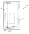
도 4는 도 3의 A - A선 단면도.4 is a cross-sectional view taken along the line AA of FIG.
도 5는 도 3의 B - B선 단면도.5 is a cross-sectional view taken along the line B-B in FIG.
도 6은 도 5에서 침입물저감스크린의 일부를 분리한 상태의 단면도. FIG. 6 is a cross-sectional view of a part of the intruder reduction screen separated from FIG. 5; FIG.
도 7은 도 3의 C - C선 단면도.7 is a cross-sectional view taken along the line C-C in FIG.
도 8은 본 발명에 따른 침입물저감스크린을 나타낸 사시도.Figure 8 is a perspective view of the intruder reduction screen according to the present invention.
도 9는 도 3의 D - D선 단면도.9 is a cross-sectional view taken along the line D-D of FIG.
도 10는 도 9을 상세히 나타낸 사시도.10 is a perspective view showing in detail FIG.
(도면중 주요 부분에 대한 부호의 설명)(Explanation of symbols for the main parts of the drawing)
100: 하수용 우수토실 10: 유입구100: sewage stormwater 10: inlet
20: 배출구 30: 부표식 자동차단밸브20: outlet 30: buoy-type shutoff valve
40: 하수도입수로 50: 웨어40: sewer inlet 50: wear
51: 조절판 51a: 장공51:
52: 볼트 60: 조목 스크린52: bolt 60: strip screen
70: 침입물저감스크린 71: 관통공70: intruder reduction screen 71: through hole
72: 유입차단날개 80: 토사적층공간부72: inlet blocking wing 80: soil stacking space
81: 경사면 90: 흡입 준설용 배관81: slope 90: piping for suction dredging
91: 축 92: 회전날개91: axis 92: rotary blade
본 발명은 하수용 우수토실에 관한 것으로, 더욱 상세하게는 우천시 우수토실내로 유입된 협잡물 및 토사가 밸브측으로 유입되는 것을 방지하기 위하여 우수토실의 내부에 침입물저감스크린을 설치하고, 우수토실 바닥면의 일정부위에 토사가 적층되도록 경사면을 형성시킨 하수용 우수토실에 관한 것이다.The present invention relates to sewage stormwater silos, and more particularly, in order to prevent the inflow of contaminants and sediment introduced into rain storm soils during rainy days to the valve side, an intrusion water reduction screen is installed inside the stormwater sills, and the bottom of storm soils The present invention relates to sewage sewage sills formed with a sloped surface such that soil is laminated on a predetermined portion of the surface.
일반적으로 하수의 배출방법은 하수(생활이나 사업에 기인하거나 수반되는 오수와 자연강우에 의한 우수를 합한 것을 말함.)의 배제형식에 따라 오수와 우수(빗물)별개의 하수관거에 의하여 배제하는 분류식과, 오수와 우수를 동일 하수관거로 배제하는 합류식이 있다.Generally, sewage discharge methods are classified by sewage (rainwater) and sewage sewer pipes according to the type of exclusion of sewage (the sum of sewage caused by life or business and accompanying rainfall from natural rainfall). For example, there is a joining ceremony to exclude sewage and rainwater from the same sewer.
신도시의 경우에는 오수와 우수(빗물)를 별개의 관거로 구성하는 분류식 관거(分流式 管渠)를 사용함으로써 모든 하수를 직접 하수처리장으로 보내기 때문에 우수토실을 사용할 필요가 없으나, 기존의 많은 도시에서는 오수와 우수를 하나의 관거를 통하여 배수하는 합류식 관거(合流式 管渠,Combined System of Sewage)를 사용하고 있어 우천시 하수시설에 대한 부담을 경감시키기 위해 우수토실의 사용은 필수적이라 할 수 있다.In the case of new towns, it is not necessary to use stormwater silos because all sewage is sent directly to the sewage treatment plant by using a sedimentation pipe, which consists of sewage and rainwater separately. In Korea, a combined system of sewage is used to drain sewage and rainwater through a single conduit. Therefore, it is essential to use rainwater silos to reduce the burden on sewage facilities in rainy weather.
이러한 우수토실은 합류식 관거에서 우천시에 일정량의 하수를 차집하여 하수처리장으로 유출하고, 나머지 하수는 하천 등의 수역으로 방류하기 위한 시설이다.Such rainwater silsoil is a facility for collecting a certain amount of sewage in rainy weather in a conduit type conduit and draining it to a sewage treatment plant, and discharging the remaining sewage into water bodies such as rivers.
도 1은 종래에 따른 하수용 우수토실의 일예를 나타낸 도면이다.1 is a view showing an example of storm sewage for sewage according to the prior art.
도시된 바와 같이 하수용 우수토실은 박스형태로 이루어지고, 일측에 하수가 유입되는 유입구(1)가 형성되고, 타측에 하수처리장으로 하수를 방출하는 배출구(2)가 형성되며, 상기 유출구(2)에는 부표식 자동차단밸브(3)가 설치된다.As shown, the sewage rainwater toil is formed in a box shape, and an
상기 부표식 자동차단밸브(3)는 하수의 양에 따라 일정량의 하수를 하수처리장으로 배출하고, 우천시와 같이 하수가 급격히 증가하며 하수처리장으로 배출되는 하수를 차단하는 밸브이다.The buoy type shut-off valve (3) is a valve for discharging a certain amount of sewage to the sewage treatment plant according to the amount of sewage, and to block the sewage discharged to the sewage treatment plant is rapidly increased as in the rain.
또한, 상기 하수용 우수토실의 유입구(1)의 주변에 형성된 하수도입수로(4)에는 일정량의 하수가 유입되도록 웨어(5) 및 협잡물을 걸려주는 조목 스크린(6)이 설치되어 있다.In addition, the sewer inlet (4) formed around the inlet (1) of the rainwater tosoil for sewage is provided with a wooden screen (6) for hanging the wear (5) and contaminants so that a certain amount of sewage flows.
상기와 같이 구성된 종래의 하수용 우수토실은 하수도입수로(4)를 통해 일정량의 하수가 유입구(1)로 유입되는데, 이때 하수도입수로(4)에 설치된 웨어(5)에 의해 일정량의 오수만이 유입구(1)로 유입된다.The conventional sewage sewage sills configured as described above have a certain amount of sewage flowing into the
또한, 유입구(1)의 전방에 조목 스크린(6)이 설치되어 하수에 포함된 협잡물 등이 조목 스크린(6)에 걸려지게 된다.In addition, the
그리고, 하수용 우수토실 내부로 유입된 하수는 부표식 자동차단밸브(3)를 통해 배출구(2)로 배출되어 하수처리장으로 이송된다.The sewage introduced into the sewage drainage chamber is discharged to the
한편, 많은 양의 우수가 하수도입수로(4)를 통해 하수용 우수토실 내부로 우수가 급격히 유입되면, 부표식 자동차단밸브(3)는 폐쇄되어 우수는 하수용 우수토실로 유입되기 전에 하천 등으로 월류된다.On the other hand, if a large amount of rainwater is rapidly introduced into the sewage storm chamber through the sewer inlet (4), the buoy-type shut-off valve (3) is closed so that the rainwater flows into the sewage stormwater stream before Overflowed by.
그러나, 종래의 하수용 우수토실은 조목 스크린(6)에서 입자가 큰 협잡물은 걸려지나, 입자가 작은 협잡물은 통과하여 하수용 우수토실 내부로 유입되고, 부표식 자동밸브(3)를 폐쇄시키는 문제점이 있다.However, the conventional sewage sewage sills are trapped with large particles of fine particles in the
또한, 하수용 우수토실 내에 쌓인 토사가 우천시 부표식 자동차단밸브(3) 측으로 유출되어 차집관로내에 퇴적됨으로 통수단면을 감소시킴과 아울러 하수처리장으로 유입되어 처리능력의 저하 및 처리비용 등의 많은 문제점이 발생되고 있다.In addition, the earth and sand accumulated in the sewage sewage chamber leaks to the buoy-
또한, 하수도입수로(4)에 설치된 웨어(5)가 고정식으로 되어 있어 주변환경의 변화에 따라 오수량이 증가하는 경우에도 하수용 우수토실에 유입되는 하수량의 조절이 어려운 문제점이 있다.In addition, there is a problem that it is difficult to control the amount of sewage flowing into the sewage excellent soil, even if the sewage amount increases according to the change of the surrounding environment because the wear (5) installed in the sewer inlet (4) is fixed.
본 발명은 이러한 종래의 문제점을 해결하기 위하여 이루어진 것으로, 그 목적은 우천시 우수토실내로 유입된 협잡물 및 토사가 밸브측으로 유입되는 것을 방지하기 위하여 우수토실의 내부에 침입물저감스크린을 설치하고, 우수토실 바닥면의 일정부위에 토사가 적층되도록 경사면을 형성시킨 하수용 우수토실을 제공함에 있다.The present invention has been made to solve such a conventional problem, the purpose is to install the intrusion water reduction screen in the inside of rainwater soil to prevent the inflow of contaminants and soil soil introduced into the rainwater storm chamber during rainy weather, excellent The present invention provides a sewage stormwater sediment in which slopes are formed so that soil is laminated on a predetermined portion of the soil floor.
또한, 본 발명의 다른 목적은 우수토실 내에 적층된 토사를 외부로 배출시키 기 위하여 흡입 준설용 배관을 설치한 하수용 우수토실을 제공함에 있다.In addition, another object of the present invention is to provide a sewage storm soil installed in the suction dredging pipe in order to discharge the earth and sand stacked in the storm soil to the outside.
또한, 본 발명의 또 다른 목적은 우수토실 내부로 유입되는 하수의 양을 조절하기 위하여 우수토실 내의 유입구 후방에 가변웨어를 설치한 하수용 우수토실을 제공함에 있다.In addition, another object of the present invention is to provide a sewage storm chamber for installing the variable wear behind the inlet in the rain storm chamber in order to control the amount of sewage flowing into the storm rain chamber.
이러한 목적을 달성하기 위한 본 발명은 박스형태로 이루어지고, 일측에 하수가 유입되는 유입구가 형성됨과 아울러 타측에 하수처리장으로 하수를 유출하는 유출구가 형성되며, 상기 유출구에는 부표식 자동차단밸브가 설치되어 지고, 상기 유입구 주변에 형성된 하수도입수로 상에 웨어 및 조목 스크린이 형성된 하수용 우수토실에 있어서, 상기 우수토실(100) 외부 웨어(50)에서 저류된 하수가 조목 스크린(60)을 통하여 협잡물을 걸려내고 우수토실 내부에는 스컴 및 토사를 유입구(10)로 유입 저감할 수 있는 침입물저감스크린(70)을 형성하고, 상기 우수토실 바닥면의 일측면에 토사가 적층되는 토사 적층공간부를 형성하며, 상기 토사 적층공간부로 토사가 유입될 수 있도록 경사면이 형성된 것이다.The present invention for achieving the above object is made in the form of a box, the inlet is formed in which the sewage inflow is formed on the other side, the outlet is formed to discharge the sewage to the sewage treatment plant on the other side, the outlet is equipped with a buoy-type shut-off valve In the rainwater sewage chamber for sewage and weeding trees formed on the sewer inlet, which is formed around the inlet, sewage accumulated in the
또한, 상기 침입물저감스크린은, 좌,우방향으로 길게 연장된 관통공이 형성되고, 상기 관통공 전방에 협잡물이 걸리는 유입차단날개가 형성되어진 것이다.In addition, the intruder reduction screen is formed with a through hole extending in the left and right directions, the inlet blocking blades are formed in the front of the through hole to catch the impurities.
또한, 상기 침입물저감스크린의 길이방향 좌,우측에 일정간격으로 절첩힌지가 형성되어진 것이다.In addition, the folded hinges are formed at regular intervals on the left and right sides of the intruder reduction screen in the longitudinal direction.
또한, 상기 웨어는, 폭방향으로 조절판이 설치되고, 상기 조절판의 높이방향으로 장공이 형성되며, 상기 장공을 통해 고정되는 볼트에 의해 하수량에 따라 높 이가 조절되는 것이다.In addition, the wear, the adjustment plate is installed in the width direction, the long hole is formed in the height direction of the control plate, the height is adjusted according to the amount of sewage by the bolt fixed through the long hole.
또한, 상기 토사 적층공간부에는 수직방향으로 흡입 준설용 배관이 설치되어 적층된 토사를 외부로 배출하도록 하는 것이다.In addition, the sediment stacking space portion is installed to the suction dredging pipe in the vertical direction to discharge the laminated soil to the outside.
이하 본 발명의 바람직한 실시예를 첨부된 도면에 의거하여 상세하게 설명하면 다음과 같다.Hereinafter, preferred embodiments of the present invention will be described in detail with reference to the accompanying drawings.
도 2 내지 도 10은 본 발명에 따른 하수용 우수토실을 나타낸 도면이다.2 to 10 is a view showing the rainwater tosoil for sewage according to the present invention.
도시한 바와 같이 본 발명에 따른 하수용 우수토실(100)은 박스형태로 이루어지고, 일측에 하수가 유입되는 유입구(10)가 형성됨과 아울러 타측에 하수처리장으로 하수를 유출하는 유출구(20)가 형성된다.As shown, the
또한, 상기 유출구(20)에는 부표식 자동차단밸브(30)가 설치되는데, 상기 부표식 자동차단밸브(30)는 하수의 양에 따라 부구가 승하강하면서 상기 유출구(20)를 차단 또는 개방시키는 것이다.In addition, the
또한, 상기 유입구(10) 주변에 형성된 하수도입수로(40) 상에 웨어(50) 및 조목 스크린(60)이 형성되어 진다.In addition, the
상기 웨어(50)는, 폭방향으로 조절판(51)이 설치되고, 상기 조절판(51)의 높이방향으로 장공(51a)이 형성되며, 상기 장공(51a)을 통해 고정되는 볼트(52)에 의해 하수의 유입량에 따라 높이가 조절되는 것이다.The
즉, 본 발명의 웨어(50)는 가변웨어로서, 주변환경에 따라 하수량이 증가하며, 웨어(50)의 높이를 조절하여 일정량의 하수가 하수용 우수토실(100)로 이송되도록 한다.That is, the
또한, 본 발명은 하수용 우수토실(100) 내부에 침입물저감스크린(70)을 설치하여, 유입구(10)의 전방에 설치된 조목 스크린(60)을 통과한 협잡물을 침입물스크린(70)에서 걸리게 된다.In addition, the present invention by installing the intrusion
상기 침입물저감스크린(70)은 좌,우방향으로 길게 연장된 관통공(71)이 형성되고, 상기 관통공(71) 전방에 협잡물이 걸리는 유입차단날개(72)가 형성되어 있어, 유입차단날개(72)에 의해 협잡물이 용이하게 걸리게 된다.The
또한, 상기 유입저감스크린(70)의 길이방향 좌,우측에 일정간격으로 절첩힌지(73)가 형성되어 설치 및 철거가 용이하게 이루어지도록 한다.In addition, the
즉, 상기 하수용 우수토실(100) 상부에 형성된 맨홀(M)의 하부에 침입물저감스크린(70)이 위치되도록 하여 상기 침입물저감스크린(70)을 하수용 우수토실(100)에서 인출하게 되면 절첩힌지(73)에 의해 절첩되어 부피를 축소시킨 상태로 운반,청소, 유지관리 등이 가능하고, 더불어 설치 작업도 용이하게 이루어진다.That is, the intrusion
또한, 도 6에 도시한 바와 같이 침입물저감스크린(70)의 일부를 분리한 상태로 우수토실에 설치할 수 있는데, 이는 절첩힌지(73)를 분리하도록 하는 것이다.In addition, as shown in Figure 6 can be installed in the rainwater chamber in a part of the
또한, 상기 하수용 우수토실(100) 바닥면의 일측면에 토사가 적층되는 토사 적층공간부(80)을 형성하며, 상기 토사 적층공간부(80)로 토사가 유입될 수 있도록 경사면(81)을 형성시킨 것이다.In addition, to form the earth and sand
즉, 상기 하수용 우수토실(100) 내부로 유입된 토사가 토사 적층공간부(80)를 중심으로 사방으로 경사면(81)을 형성하여 토사가 쌓이게 하는 것이다.That is, the earth and sand introduced into the sewage
상기와 같이 토사 적층공간부(80)에 적층된 토사는 수직방향으로 설치된 흡 입 준설용 배관(90)에 의해 적층된 토사를 외부로 배출하게 되는데, 상기 흡입 준설용 배관(90)의 하단부에 형성된 관통공(91)을 통해 토사가 유입된다.The earth and sand stacked in the soil stacking
즉, 상기 흡입 준설용 배관(90)의 내부에 흡입펌프(미도시)에 연결된 호스를 연결하여 준설하도록 한다.That is, the dredging by connecting a hose connected to the suction pump (not shown) in the
본 발명에 따른 작용을 상세히 설명하면 다음과 같다.Referring to the operation according to the invention in detail as follows.
하수도입수로(40)를 통해 유입되는 하수는 웨어(50)를 통해 저류하게 되는데, 하수의 양에 따라 조절판(51)을 높이방향으로 조절하도록 하는 것이다.The sewage flowing through the
즉, 생활하수가 적게 발생되는 지역에서는 조절판(51)의 높이를 낮추고, 인구의 증가 등으로 생활하수가 증가하게 되면 조절판(51)의 높이를 높이게 된다.That is, in an area in which small living sewage is generated, the height of the adjusting
또한, 상기 웨어(50)로 인해 저류된 하수는 유입구(10)의 전방에 설치된 조목 스크린(60)에서 협잡물이 걸리게 되며, 상기 조목 스크린(60)을 통과한 미세한 협잡물은 하수용 우수토실(100) 내부에 설치된 침입물저감스크린(70)에 의해 걸리게 된다.In addition, the sewage stored by the
이는 상기 침입물저감스크린(70)에 형성된 유입차단날개(72)에 의해 협잡물이 용이하게 걸리게 되며, 오수만이 관통공(71)을 통해 부표식 자동차단밸브(30) 측으로 이송되도록 하여 협잡물이 하수처리장으로 이송되는 것을 방지하게 된다.It is easily caught by the
또한, 상기 하수용 우수토실(100)의 내부에는 하수와 함께 토사가 많이 쌓이게 되는데 상기 토사는 하수용 우수토실(100) 바닥면의 일정위치에 형성된 토사 적층공간부(80)에 모이게 된다.In addition, the sewage piled together with the sewage in the interior of the sewage
상기와 같이 토사 적층공간부(80)에 모인 토사는 흡입 준설용 배관(90)에 흡 입펌프에 연결된 호스를 연결하여 토사를 준설하게 된다.The earth and sand collected in the soil stacking
본 발명은 첨부된 도면에 도시된 일 실시예를 참고로 설명한 것이나, 당해 기술 분야의 통상의 지식을 가진 자들에게는 다양한 변형 및 다른 실시예가 가능하다는 점이 이해될 것이다.Although the present invention has been described with reference to one embodiment shown in the accompanying drawings, it will be understood that various modifications and other embodiments are possible to those skilled in the art.
이상 상세히 설명한 바와 같은 본 발명에 따른 하수용 우수토실은 우수토실의 내부에 침입물저감스크린을 설치하고, 우수토실 바닥면의 일정부위에 토사가 적층되도록 경사면을 형성시킴으로서, 우천시 우수토실내로 유입된 협잡물 및 토사가 밸브측으로 유입되는 것을 방지할 수 있다.The sewage stormwater silos according to the present invention as described in detail above are provided with an intrusion water reduction screen in the interior of rainwater storm sills, and the slopes are formed so that the soil is laminated on a predetermined portion of the bottom of rainwater sills, and it flows into rain storm soil during rainy weather. It is possible to prevent the collected dirt and soil to enter the valve side.
또한, 본 발명에 따른 하수용 우수토실은 토사를 외부로 배출시키는 흡입 준설용 배관을 설치하여 토사의 배출이 용이하게 이루어진다.In addition, the sewage sewage silt according to the present invention is installed by the suction dredging pipe for discharging the soil to the outside made easy to discharge the soil.
또한, 본 발명에 따른 하수용 우수토실은 우수토실 내의 유입구 후방에 가변웨어를 설치하여 우수토실 내부로 유입되는 하수의 양을 조절할 수 있다.In addition, the storm sewage for sewage according to the present invention can adjust the amount of sewage flowing into the rainwater chamber by installing a variable wear behind the inlet in the rainwater chamber.
Claims (5)
Priority Applications (1)
| Application Number | Priority Date | Filing Date | Title |
|---|---|---|---|
| KR1020060090012A KR100684923B1 (en) | 2006-09-18 | 2006-09-18 | Sanitary pipe storm water inflow for sewage water |
Applications Claiming Priority (1)
| Application Number | Priority Date | Filing Date | Title |
|---|---|---|---|
| KR1020060090012A KR100684923B1 (en) | 2006-09-18 | 2006-09-18 | Sanitary pipe storm water inflow for sewage water |
Publications (1)
| Publication Number | Publication Date |
|---|---|
| KR100684923B1 true KR100684923B1 (en) | 2007-02-22 |
Family
ID=38104141
Family Applications (1)
| Application Number | Title | Priority Date | Filing Date |
|---|---|---|---|
| KR1020060090012A KR100684923B1 (en) | 2006-09-18 | 2006-09-18 | Sanitary pipe storm water inflow for sewage water |
Country Status (1)
| Country | Link |
|---|---|
| KR (1) | KR100684923B1 (en) |
Cited By (12)
| Publication number | Priority date | Publication date | Assignee | Title |
|---|---|---|---|---|
| KR100834532B1 (en) | 2007-05-15 | 2008-06-02 | 전완재 | Device for preventing earth and sand from confluent |
| KR100865253B1 (en) * | 2008-05-30 | 2008-10-24 | (자)한진개발공사 | First flush stormwater treatment apparatus |
| KR101000026B1 (en) * | 2010-05-20 | 2010-12-09 | 코리아이엔티 주식회사 | Automatic flow rate control equipment |
| KR101038806B1 (en) * | 2008-11-19 | 2011-06-03 | 이병관 | Manhole |
| KR101147214B1 (en) * | 2009-09-18 | 2012-05-29 | 장진택 | Treatment facility for muddy water |
| KR101147216B1 (en) * | 2009-09-18 | 2012-05-29 | 블루그린링크(주) | Treatment facility for muddy water |
| WO2014182029A1 (en) * | 2013-05-06 | 2014-11-13 | Han Byungsook | Rainwater discharge chamber capable of discharging rainwater and soil |
| GB2549959A (en) * | 2016-05-03 | 2017-11-08 | Munn Samuel | Automatic screen cleaning apparatus |
| CN110117986A (en) * | 2019-05-13 | 2019-08-13 | 安徽理工大学 | A kind of drainage well structure and operation method convenient for rubbish cleaning |
| CN110230347A (en) * | 2019-07-15 | 2019-09-13 | 江苏华蕊海绵城市建设有限公司 | A kind of rain sewage diversion device |
| CN114319547A (en) * | 2021-12-10 | 2022-04-12 | 高邮市恒立液压成套设备有限公司 | Conveniently block integrated form intelligence reposition of redundant personnel well of intaking |
| KR102653997B1 (en) * | 2021-05-25 | 2024-04-02 | 전상훈 | Water storage type flow control device for storm overflow chamber |
Citations (5)
| Publication number | Priority date | Publication date | Assignee | Title |
|---|---|---|---|---|
| KR200166989Y1 (en) * | 1998-02-02 | 2000-01-15 | 제성호 | Auto opening and closing device of a room for exhaust rain water in a drainpipe |
| KR200195178Y1 (en) * | 2000-01-17 | 2000-09-01 | 주식회사범한엔지니어링 | Grit removal basins in combined sewerage. |
| JP2002310533A (en) * | 2001-04-11 | 2002-10-23 | Kubota Corp | Sewage heat recovering device |
| KR100473604B1 (en) * | 2002-06-26 | 2005-03-10 | 주식회사 평화티씨엠 건축사사무소 | A soil and foul water prirate use plastics a manhol |
| KR200388672Y1 (en) * | 2005-04-06 | 2005-07-01 | (주)화신엔지니어링 | Assembly type manhole for sewage |
-
2006
- 2006-09-18 KR KR1020060090012A patent/KR100684923B1/en active IP Right Grant
Patent Citations (5)
| Publication number | Priority date | Publication date | Assignee | Title |
|---|---|---|---|---|
| KR200166989Y1 (en) * | 1998-02-02 | 2000-01-15 | 제성호 | Auto opening and closing device of a room for exhaust rain water in a drainpipe |
| KR200195178Y1 (en) * | 2000-01-17 | 2000-09-01 | 주식회사범한엔지니어링 | Grit removal basins in combined sewerage. |
| JP2002310533A (en) * | 2001-04-11 | 2002-10-23 | Kubota Corp | Sewage heat recovering device |
| KR100473604B1 (en) * | 2002-06-26 | 2005-03-10 | 주식회사 평화티씨엠 건축사사무소 | A soil and foul water prirate use plastics a manhol |
| KR200388672Y1 (en) * | 2005-04-06 | 2005-07-01 | (주)화신엔지니어링 | Assembly type manhole for sewage |
Non-Patent Citations (4)
| Title |
|---|
| 등록번호 제10-0473604호 |
| 등록번호 제20-0166989호 |
| 등록번호 제20-0195178호 |
| 등록번호 제20-0388672호 |
Cited By (16)
| Publication number | Priority date | Publication date | Assignee | Title |
|---|---|---|---|---|
| KR100834532B1 (en) | 2007-05-15 | 2008-06-02 | 전완재 | Device for preventing earth and sand from confluent |
| KR100865253B1 (en) * | 2008-05-30 | 2008-10-24 | (자)한진개발공사 | First flush stormwater treatment apparatus |
| KR101038806B1 (en) * | 2008-11-19 | 2011-06-03 | 이병관 | Manhole |
| KR101147214B1 (en) * | 2009-09-18 | 2012-05-29 | 장진택 | Treatment facility for muddy water |
| KR101147216B1 (en) * | 2009-09-18 | 2012-05-29 | 블루그린링크(주) | Treatment facility for muddy water |
| KR101000026B1 (en) * | 2010-05-20 | 2010-12-09 | 코리아이엔티 주식회사 | Automatic flow rate control equipment |
| US10883262B2 (en) | 2013-05-06 | 2021-01-05 | Byungsook HAN | Overflow chamber for emission of rainwater and soil |
| JP2016524057A (en) * | 2013-05-06 | 2016-08-12 | スク ハン,ビョン | Rainwater spout chamber capable of discharging rainwater and earth and sand |
| WO2014182029A1 (en) * | 2013-05-06 | 2014-11-13 | Han Byungsook | Rainwater discharge chamber capable of discharging rainwater and soil |
| GB2549959A (en) * | 2016-05-03 | 2017-11-08 | Munn Samuel | Automatic screen cleaning apparatus |
| GB2549959B (en) * | 2016-05-03 | 2020-11-25 | Munn Samuel | Automatic screen cleaning apparatus |
| CN110117986A (en) * | 2019-05-13 | 2019-08-13 | 安徽理工大学 | A kind of drainage well structure and operation method convenient for rubbish cleaning |
| CN110117986B (en) * | 2019-05-13 | 2024-01-09 | 安徽理工大学 | Rainwater well structure convenient for garbage cleaning and operation method |
| CN110230347A (en) * | 2019-07-15 | 2019-09-13 | 江苏华蕊海绵城市建设有限公司 | A kind of rain sewage diversion device |
| KR102653997B1 (en) * | 2021-05-25 | 2024-04-02 | 전상훈 | Water storage type flow control device for storm overflow chamber |
| CN114319547A (en) * | 2021-12-10 | 2022-04-12 | 高邮市恒立液压成套设备有限公司 | Conveniently block integrated form intelligence reposition of redundant personnel well of intaking |
Similar Documents
| Publication | Publication Date | Title |
|---|---|---|
| KR100684923B1 (en) | Sanitary pipe storm water inflow for sewage water | |
| US20090279954A1 (en) | Debris and sediment reduction apparatus for water drainage systems | |
| CA2929096C (en) | Closed flow sewer system | |
| KR101039196B1 (en) | Keeping treatment system for primary stage rainwater using the water-storage tank | |
| KR100990483B1 (en) | Keeping treatment system for primary stage rainwater | |
| KR102035183B1 (en) | Apparatus for Prevention Sediment of Flap Door Gate | |
| KR100941693B1 (en) | Drain box | |
| KR101369130B1 (en) | Flow control device of sewage gathering duct with integrated checking hole | |
| KR101241459B1 (en) | Initial rainwater keeping treatment system with a extended water-storage tank | |
| CN102444199B (en) | Anti-blocking rain water cover | |
| KR101316313B1 (en) | Keeping treatment system of primary stage rainwater for valleywater using the water-storage tank | |
| KR101468324B1 (en) | Rainwater Storage-System For Automatic and Semi-Automatic | |
| CN106522354A (en) | Water-intercepting type drainage pumping station provided with oblique plates or oblique tubes for separation | |
| CN107460938A (en) | A kind of osmosis type roads rain inlet with secondary heavy mud function | |
| US10060117B1 (en) | Stormwater runoff separator and collector for curb inlet type catch basins | |
| KR100986644B1 (en) | Rainwater treatment system | |
| KR101151090B1 (en) | Keeping treatment system for primary stage rainwater using the water-storage tank | |
| CN114319537A (en) | Can strengthen sponge system of rainwater purification infiltration function | |
| KR100625746B1 (en) | Suspended Material Auto-draw Chamber | |
| CN207295943U (en) | A kind of road drainage system | |
| CN213014614U (en) | Box culvert cuts dirty regulation and storage structure | |
| KR20160050465A (en) | Apparatus for treating rainwater of marginal strip | |
| KR100730993B1 (en) | Intake Facility for First runoff in Stream | |
| KR101224234B1 (en) | Keeping treatment system for primary stage rainwater using water-storage tank | |
| CN220599867U (en) | Siphon tunnel drainage system |
Legal Events
| Date | Code | Title | Description |
|---|---|---|---|
| A201 | Request for examination | ||
| A302 | Request for accelerated examination | ||
| E701 | Decision to grant or registration of patent right | ||
| GRNT | Written decision to grant | ||
| FPAY | Annual fee payment |
Payment date: 20130209 Year of fee payment: 7 |
|
| FPAY | Annual fee payment |
Payment date: 20140210 Year of fee payment: 8 |
|
| FPAY | Annual fee payment |
Payment date: 20150212 Year of fee payment: 9 |
|
| FPAY | Annual fee payment |
Payment date: 20170213 Year of fee payment: 11 |
|
| FPAY | Annual fee payment |
Payment date: 20180213 Year of fee payment: 12 |
|
| FPAY | Annual fee payment |
Payment date: 20190213 Year of fee payment: 13 |
|
| FPAY | Annual fee payment |
Payment date: 20200213 Year of fee payment: 14 |