KR100670866B1 - Apparatus and process for spinning polymeric filaments - Google Patents
Apparatus and process for spinning polymeric filaments Download PDFInfo
- Publication number
- KR100670866B1 KR100670866B1 KR1020017013057A KR20017013057A KR100670866B1 KR 100670866 B1 KR100670866 B1 KR 100670866B1 KR 1020017013057 A KR1020017013057 A KR 1020017013057A KR 20017013057 A KR20017013057 A KR 20017013057A KR 100670866 B1 KR100670866 B1 KR 100670866B1
- Authority
- KR
- South Korea
- Prior art keywords
- stage
- filament
- gas
- chamber
- gas inlet
- Prior art date
Links
Images


Classifications
-
- D—TEXTILES; PAPER
- D01—NATURAL OR MAN-MADE THREADS OR FIBRES; SPINNING
- D01D—MECHANICAL METHODS OR APPARATUS IN THE MANUFACTURE OF ARTIFICIAL FILAMENTS, THREADS, FIBRES, BRISTLES OR RIBBONS
- D01D5/00—Formation of filaments, threads, or the like
- D01D5/08—Melt spinning methods
- D01D5/088—Cooling filaments, threads or the like, leaving the spinnerettes
- D01D5/092—Cooling filaments, threads or the like, leaving the spinnerettes in shafts or chimneys
-
- D—TEXTILES; PAPER
- D01—NATURAL OR MAN-MADE THREADS OR FIBRES; SPINNING
- D01D—MECHANICAL METHODS OR APPARATUS IN THE MANUFACTURE OF ARTIFICIAL FILAMENTS, THREADS, FIBRES, BRISTLES OR RIBBONS
- D01D13/00—Complete machines for producing artificial threads
Abstract
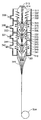
연속 중합성 필라멘트를 방사하기 위한 용융 방사 장치는 방사구(113) 아래에 위치되도록 제조된 제1 스테이지 가스 입구 챔버(105) 및 제1 스테이지 가스 입구 챔버 아래에 위치된 선택적인 제2 스테이지 가스 입구 챔버(106)를 포함한다. 가스 입구 챔버는 필라멘트의 온도를 제어하기 위해 필라멘트에 가스를 공급한다. 용융 방사 장치는 또한 필라멘트가 냉각될 때 필라멘트를 둘러싸기 위해 제2 스테이지 가스 입구 챔버 아래에 위치된 튜브(119)를 포함한다. 튜브는 수렴 섹션 및 선택적으로 그 다음에 위치한 발산 섹션을 갖는 내부벽을 포함할 수 있다.The melt spinning apparatus for spinning continuous polymerizable filaments includes a first stage gas inlet chamber 105 and an optional second stage gas inlet positioned below the first stage gas inlet chamber that are fabricated to be positioned below the spinneret 113. Chamber 106. The gas inlet chamber supplies gas to the filament to control the temperature of the filament. The melt spinning apparatus also includes a tube 119 positioned below the second stage gas inlet chamber to surround the filament when the filament is cooled. The tube may comprise an inner wall having a converging section and optionally a diverging section located thereafter.
하우징, 내벽, 방사구, 필라멘트, 수렴 섹션Housing, Inner Wall, Spinneret, Filament, Converging Section
Description
본 출원은 1999년 4월 15일 가출원된 제60/129412호를 기초로 우선권 주장한 출원으로 그 전체 내용은 본 명세서에 인용되어 합체되어 있다.This application is a priority application on the basis of Provisional Application No. 60/129412 filed April 15, 1999, the entire contents of which are incorporated herein by reference.
본 발명은 폴리에스테르 필라멘트를 위해, 예컨대 분당 3500미터(mpm) 이상의 고속으로 중합성 필라멘트를 용융 방사하기 위한 방법 및 장치에 관한 것이다. The present invention relates to a method and apparatus for melt spinning polymeric filaments for polyester filaments, for example at high speeds of at least 3500 meters per minute (mpm).
폴레에스테르와 같은 대부분의 중합성 필라멘트는 용융 방사된다. 즉, 대부분의 중합성 필라멘트는 고온 중합성 용융물로부터 압출된다. 현행 방법에서는, 새로이 압출된 용융 필라멘트 스트림(stream)이 방사구로부터 나오면, 필라멘트 스트림의 경화를 촉진시키기 위해 이들 스트림은 냉각 가스의 기류에 의해 급냉된다. 그 후 필라멘트 스트림은 권취되어서 한 묶음의 연속 필라멘트사를 형성하거나, 예컨대 단섬유(staple)로 전환하기 위해, 예컨대 연속 필라멘트 토우(tow)로서 가공하거나 다른 가공을 위해서, 예컨대 한 다발의 평행한 연속 필라멘트로서 수집되는 것과 같이 다르게 가공될 수 있다.Most polymerizable filaments such as polyesters are melt spun. That is, most of the polymerizable filaments are extruded from the hot polymerizable melt. In the current process, as freshly extruded molten filament streams emerge from the spinneret, these streams are quenched by an airflow of cooling gas to promote curing of the filament streams. The filament stream is then wound up to form a bundle of continuous filament yarns, or for example to convert into a staple, for example as a continuous filament tow or for another machining, for example in one bundle of parallel continuous It can be processed differently, such as collected as filaments.
오랫동안 공지되어 온 바에 따르면, 폴리에스테르와 같은 중합성 필라멘트는 대략 5 ㎞/분 이상의 고속으로 방사함으로써 연신을 하지 않고도 직접, 즉 기존 방사 조건에서 마련될 수 있다. 헤벨러(Hebeler)의 미국 특허 제2,604,667호에서는 폴리에스테르를 위한 방법을 개시하고 있다. 또한, 방사 장치에서 용융 필라멘트를 냉각하거나 급랭하는 것에 대해 많은 관심이 주어져 왔다. 일반적으로, WO 00 05439, WO 95 15409, EP 0 334 604, JP 84107 및 JP 602 46807호를 참조한다.It has been known for a long time that polymerizable filaments such as polyester can be prepared directly, ie under existing spinning conditions, without stretching by spinning at high speeds of approximately 5 km / min or more. Hebeler US Pat. No. 2,604,667 discloses a process for polyesters. In addition, much attention has been given to cooling or quenching the molten filaments in the spinning apparatus. In general, reference is made to WO 00 05439, WO 95 15409, EP 0 334 604, JP 84107 and JP 602 46807.
일반 상업용으로서는 본질적으로 두 종류의 기본적인 급냉 시스템이 있다. 이제까지 상업상 선호되어 사용되 온 것은 교차 유동 급냉이다. 교차 유동 급냉은 새로이 압출된 용융 필라멘트 어레이의 어느 한 측면을 가로질러 이로부터 냉각 가스를 취입하는 단계를 포함한다. 교차 유동 공기의 대부분은 필라멘트 어레이의 다른 측면을 관통해서 나온다. 그러나, 여러 인자에 따라, 일부 공기는 필라멘트에 의해 포획되어서 일반적으로 각각의 방사 위치의 기부에서 구동되고 존재하는 당김 롤(roll)쪽으로 필라멘트들과 함께 하향 운반된다. 많은 섬유 기술 공장에서는 "교차 유동 냉각"이 속도 증가 및 관통 인입(through-put)에 요구되는 대량의 냉각 가스를 취입하는 데 가장 좋은 방법을 제공한다고 믿기 때문에, 당김 롤 속도(일반적으로 회수 속도로 알려져 있으며 때로는 방사 속도로 지칭됨)가 증가함에 따라 일반적으로 교차 유동을 선호해 왔다.There are essentially two basic quenching systems in general commercial use. What has been the preferred commercial choice so far is cross-flow quenching. Cross flow quenching includes blowing cooling gas therefrom across either side of the newly extruded molten filament array. Most of the cross flow air passes through the other side of the filament array. However, depending on several factors, some air is captured by the filaments and is generally driven at the base of each spinning position and carried down with the filaments towards the existing pull roll. Many textile technology plants believe that "cross flow cooling" provides the best way to blow up the bulk of the cooling gas required for speed increase and through-put, so the pull roll speed (usually Known and sometimes referred to as spinning speed) has generally favored cross flow.
다른 유형의 급냉은 "방사상 급냉"이며, 예컨대 녹스(Knox)의 미국 특허 제4,156,071호와 콜린스(Collins) 등의 미국 특허 제5,250,245호 및 제5,288,553호에 개시된 바와 같이, 몇몇 중합성 필라멘트를 상업적으로 제조하는 데 사용되어 왔다. 이런 유형의 "방사상 급냉"에서, 냉각 가스는 새로이 압출된 필라멘트 어레이를 둘러싸는 급냉 스크린 시스템을 거쳐 안으로 향하게 된다. 이런 냉각 가스는 일반적으로 급냉 장치를 나와서 필라멘트와 함께 전달됨으로써 냉각 시스템으로부터 벗어난다. 비록, 원형의 필라멘트 어레이에 대해서는 "방사상 급냉"이란 용어 가 적절하지만, 필라멘트 어레이가 원형이 아니고, 예컨대 직사각형, 타원형 또는 다른 형상인 경우에도 냉각 가스를 필라멘트 어레이쪽으로 내향시키는 대응하는 형상의 주변 스크린 시스템을 가진 동일한 시스템은 거의 유사하게 작동할 수 있다.Another type of quench is "radial quench", and some polymeric filaments are commercially commercialized, for example, as disclosed in U.S. Pat. Nos. 4,156,071 to Knox and U.S. Pat. It has been used to make. In this type of "radial quench", the cooling gas is directed in through a quench screen system surrounding the newly extruded filament array. Such cooling gas generally exits the quench system and is delivered with the filament to escape the cooling system. Although the term "radial quenching" is appropriate for circular filament arrays, a peripheral screen system of corresponding shape that directs cooling gas towards the filament array even when the filament array is not circular, e.g. rectangular, elliptical or otherwise. The same system can be operated almost similarly.
1980년대에, 바실라토스(Vassilatos)와 스즈(Sze)는 중합성 필라멘트의 고속 방사를 크게 개선하였으며 미국 특허 제4,687,610호, 제4,691,003호, 제5,141,700호 및 제5,034,183호에서 그 내용과 최종 개선된 필라멘트를 개시하였다. 이들 특허에서는 가스 조절 기술에 대해 개시하고 있으며, 이 기술에서 가스는 필라멘트의 온도와 감쇄 프로파일을 제어하기 위해 새로이 압출된 필라멘트를 둘러싼다. 비록 이들 특허는 고속 방사 분야의 돌파구가 되었지만, 적어도 실의 질을 떨어뜨리지 않거나 개선시키면서 회수 속도를 증가시켜서 방사 생산성을 증가시키고자 하는 기대를 충족시키고 있지는 않다.In the 1980s, Vassilatos and Sze significantly improved the high speed spinning of polymerizable filaments and their content and final improvements in US Pat. Nos. 4,687,610, 4,691,003, 5,141,700 and 5,034,183. Filament is disclosed. These patents describe a gas conditioning technique in which the gas surrounds the newly extruded filaments to control the temperature and attenuation profile of the filament. Although these patents are breakthroughs in the field of high speed spinning, they do not meet the expectations of increasing spinning productivity by increasing the recovery rate, at least without compromising or improving the quality of the yarn.
이런 필요성에 따라, 중합성 필라멘트를 방사하기 위한 장치 및 방법이 마련된다.In accordance with this need, an apparatus and method for spinning polymerizable filaments are provided.
본 발명의 일 태양에 따르면, According to one aspect of the invention,
방사구 아래에 위치되도록 제조된 제1 스테이지 가스 입구 챔버 및 제1 스테이지 가스 입구 챔버 아래에 위치된 제2 스테이지 가스 입구 챔버와,A first stage gas inlet chamber and a second stage gas inlet chamber positioned below the spinneret, the second stage gas inlet chamber positioned below the first stage gas inlet chamber;
필라멘트가 냉각될 때 필라멘트를 둘러싸기 위해 제2 스테이지 가스 입구 챔버 아래에 위치되고 수렴 섹션 및 그 다음에 위치된 발산 섹션을 갖는 내부벽을 포함하는 튜브를 포함하며, 각각의 스테이지 가스 입구 챔버는 필라멘트의 온도를 제 어하기 위해 필라멘트에 가스를 공급하는 연속 중합성 필라멘트를 방사하기 위한 용융 방사 장치가 마련된다.When the filaments are cooled, they comprise a tube positioned below the second stage gas inlet chamber to enclose the filaments and including an inner wall having a converging section and a diverging section located thereafter, each stage gas inlet chamber of the filament A melt spinning apparatus is provided for spinning continuous polymeric filaments that supply gas to the filaments to control the temperature.
본 발명의 다른 태양에 따르면,According to another aspect of the invention,
방사구 아래에 위치되도록 제조된 하우징과,A housing manufactured to be positioned below the spinneret;
각각 하우징의 내벽에 형성된 제1 스테이지 챔버 및 제2 스테이지 챔버와,A first stage chamber and a second stage chamber each formed on an inner wall of the housing;
제1 스테이지 챔버로 가스를 공급하기 위한 제1 스테이지 가스 입구와,A first stage gas inlet for supplying gas to the first stage chamber,
제2 스테이지 챔버로 가스를 공급하기 위한 제2 스테이지 가스 입구와,A second stage gas inlet for supplying gas to the second stage chamber,
제2 스테이지 챔버로부터 제1 스테이지 챔버를 분리시키기 위해 제1 스테이지 챔버의 하부에서 내벽에 부착된 벽과,A wall attached to the inner wall at the bottom of the first stage chamber to separate the first stage chamber from the second stage chamber,
제1 스테이지 챔버에서 중심에 위치된 급냉 스크린과,A quench screen located centrally in the first stage chamber,
급냉 스크린의 아래에서 제1 스테이지 가스 입구 및 제2 스테이지 가스 입구 사이에 배치된 내벽과,An inner wall disposed below the quench screen between the first stage gas inlet and the second stage gas inlet,
내벽의 내부에 형성된 제1 스테이지 수렴 섹션과,A first stage converging section formed inside the inner wall,
제1 스테이지 수렴 섹션 아래에서 제1 스테이지 가스 입구 및 제2 스테이지 가스 입구 사이에 배치되고 제2 스테이지 챔버 내의 중심에 위치된 천공 튜브와,A perforated tube disposed between the first stage gas inlet and the second stage gas inlet below the first stage convergence section and positioned centrally in the second stage chamber;
천공 튜브 아래에 위치된 내벽과,An inner wall located under the perforated tube,
내벽의 내부에 위치되고 제2 스테이지 챔버 내에 위치된 제2 스테이지 수렴 섹션 및 제2 스테이지 챔버의 출구에 위치된 발산 섹션을 갖는 내부벽을 포함하는 튜브와,A tube comprising an inner wall having a second stage converging section located within the inner wall and located in the second stage chamber and a diverging section located at the outlet of the second stage chamber;
튜브의 출구에 위치된 관통벽을 갖는 선택적인 수렴 콘(cone)을 포함하며, An optional converging cone having a through wall located at the outlet of the tube,
장치는 가압된 가스가 제1 스테이지 가스 입구로부터 제1 스테이지 챔버를 통해서 급냉 스크린의 내벽에 형성된 영역으로 내향 취입되도록 제조된, 연속 중합성 필라멘트를 방사하기 위한 용융 방사 장치가 마련된다.The apparatus is provided with a melt spinning apparatus for spinning continuous polymerizable filaments, wherein the pressurized gas is blown inwardly through the first stage chamber into a region formed in the inner wall of the quench screen.
본 발명의 다른 태양에 따르면, 필라멘트를 형성하기 위해 방사구 내에서 가열된 중합성 용융물을 통과시키는 단계와, 제1 스테이지의 방사구 아래에 위치된 가스 입구 챔버로부터 필라멘트에 가스를 제공하는 단계와, 제2 스테이지의 가스 입구 챔버로부터 필라멘트에 가스를 제공하는 단계와, 제1 수렴 섹션을 갖는 내부벽을 포함하고 가스 입구 챔버 아래에 위치된 튜브에 필라멘트를 통과시키는 단계와, 튜브를 통해서 필라멘트를 통과시키는 단계를 포함하는, 연속 중합성 필라멘트를 방사하기 위한 용융 방사 방법이 마련된다.According to another aspect of the invention, there is provided a method of producing a filament, the method comprising: passing a heated polymerizable melt in a spinneret to provide a filament, and providing gas to the filament from a gas inlet chamber located below the spinneret of the first stage; Providing gas to the filament from the gas inlet chamber of the second stage, passing the filament through a tube comprising an inner wall having a first converging section and located below the gas inlet chamber, passing the filament through the tube A melt spinning method is provided for spinning a continuous polymerizable filament, the method comprising the step of:
본 발명의 다른 실시예에 따르면, 필라멘트를 둘러싸는 튜브와, 방사구 아래에 위치되도록 제조되고 필라멘트의 온도를 제어하기 위해 필라멘트에 가스를 공급하고 장치로부터 공기를 제거하도록 제조된 적어도 하나의 배출 스테이지를 포함하는 둘 이상의 가스 입구 챔버를 추가로 포함하는, 연속 중합성 필라멘트를 방사하기 위한 용융 방사 장치가 마련된다.According to another embodiment of the invention, the tube surrounding the filament and at least one discharge stage made to be positioned below the spinneret and manufactured to supply gas to the filament and remove air from the device to control the temperature of the filament Further comprising a two or more gas inlet chamber comprising a molten spinning apparatus for spinning the continuous polymerizable filament is provided.
본 발명의 다른 태양에 따르면, According to another aspect of the invention,
필라멘트를 형성하기 위해 방사구 내에 가열된 중합성 용융물을 통과시키는 단계와,Passing the heated polymeric melt into the spinneret to form a filament,
제1 스테이지의 방사구 아래에 위치된 가스 입구 챔버로부터 필라멘트에 가스를 제공하는 단계와, Providing gas to the filament from a gas inlet chamber located below the spinneret of the first stage;
제1 스테이지 아래에 위치된 적어도 하나의 가스 배출 챔버로부터 가스를 배출하기 위한 수단을 제공하는 단계와,Providing means for evacuating gas from at least one gas exhaust chamber located below the first stage;
가스 입구 챔버 아래에 위치되고 공기 속도를 증가시키는 제1 수렴 섹션을 갖는 내부벽을 포함하는 튜브를 거쳐 필라멘트를 통과시키는 단계와,Passing the filament through a tube comprising an inner wall positioned below the gas inlet chamber and having a first converging section for increasing air velocity;
필라멘트가 튜브를 빠져나가는 단계를 포함하는, 연속 중합성 필라멘트를 방사하기 위한 용융 방사 방법이 마련된다.A melt spinning method is provided for spinning continuous polymerizable filaments, including filaments exiting the tube.
본 발명의 다른 실시예에서는, 필라멘트를 둘러싸기 위한 튜브와, 방사구 아래에 위치되도록 제조된 하나 이상의 가스 입구와, 가스를 제거하기 위한 진공 배출구을 포함하며, 적어도 하나의 가스 입구는 필라멘트의 온도를 제어하기 위해 대기압보다 높은 압력에서 필라멘트에 가스를 공급하기 위한 수단을 포함하는, 연속 중합성 필라멘트를 방사하기 위한 용융 방사 장치가 마련된다.In another embodiment of the present invention, there is provided a tube for enclosing the filament, at least one gas inlet manufactured to be positioned below the spinneret, and a vacuum outlet for removing gas, wherein the at least one gas inlet is at a temperature of the filament. A melt spinning apparatus is provided for spinning continuous polymeric filaments, comprising means for supplying gas to the filaments at pressures above atmospheric pressure for control.
본 발명의 다른 태양에서는, 필라멘트가 냉각될 때 필라멘트를 둘러싸기 위한 가스 입구 챔버 아래에 위치된 튜브를 포함하며, 튜브는 가스를 가속시키기 위한 수렴 섹션과 그 다음에 위치된 발산 섹션을 포함하는 내부벽을 포함하는 연속 중합성 필라멘트를 방사하기 위한 용융 방사 장치가 추가로 마련된다.In another aspect of the present invention, a filament includes a tube positioned below a gas inlet chamber for enclosing the filament when the filament is cooled, the tube having an inner wall comprising a converging section for accelerating the gas and a diverging section located thereafter. Further provided is a melt spinning apparatus for spinning a continuous polymerizable filament comprising a.
본 발명의 다른 실시예에서는,In another embodiment of the invention,
방사구 아래에 위치되도록 제조된 하우징과,A housing manufactured to be positioned below the spinneret;
각각 하우징의 내벽 내에 형성된 제1 스테이지 챔버, 제2 스테이지 챔버 및 제3 스테이지 챔버와,A first stage chamber, a second stage chamber, and a third stage chamber each formed in an inner wall of the housing;
제1 스테이지 챔버에 가스를 공급하기 위한 제1 스테이지 가스 입구와, A first stage gas inlet for supplying gas to the first stage chamber,
제2 스테이지 챔버로 공급하거나 제2 스테이지 챔버로부터 가스를 배출하기 위한 제2 스테이지 가스 입구와,A second stage gas inlet for supplying to or discharging gas from the second stage chamber;
제3 스테이지 챔버에 가스를 공급하기 위한 제3 스테이지 가스 입구와,A third stage gas inlet for supplying gas to the third stage chamber,
가스를 가속시키기 위해 적어도 하나의 스테이지 내에 또는 제3 스테이지 다음에 위치한 수렴 섹션을 포함하는, 연속 중합성 필라멘트를 방사하기 위한 용융 방사 장치가 추가로 마련된다.There is further provided a melt spinning apparatus for spinning continuous polymeric filaments, comprising a converging section located within at least one stage or next to the third stage to accelerate the gas.
본 발명의 일 실시예에는, In one embodiment of the present invention,
방사구 아래에 위치되도록 제조되고 필라멘트의 온도를 제어하기 위해 필라멘트에 가스를 공급하는 둘 이상의 가스 입구 챔버와,At least two gas inlet chambers manufactured to be positioned below the spinneret and supplying gas to the filaments for controlling the temperature of the filaments,
하나 이상의 입구 챔버로 가스를 공급하기 위한 적어도 하나의 가스 입구와,At least one gas inlet for supplying gas to at least one inlet chamber,
입구 챔버를 구분하는 적어도 하나의 천공된 환형판과,At least one perforated annular plate defining an inlet chamber,
필라멘트가 냉각될 때 필라멘트를 둘러싸고 수렴 섹션 및 그 다음에 위치한 선택적인 발산 섹션을 갖는 내부벽을 포함하는, 연속 중합성 필라멘트를 방사하기 위한 용융 방사 장치도 마련된다. There is also provided a melt spinning apparatus for spinning continuous polymeric filaments that includes an inner wall having a converging section and an optional diverging section located thereafter surrounding the filament when the filament is cooled.
본 발명의 일 태양에서는, 적어도 두 개의 스테이지에서 필라멘트로 냉각 가스를 제공하는 단계와, 스테이지 사이에서 가스를 가속시키는 단계를 포함하는 용융 방사 폴리에스테르 필라멘트를 냉각시키기 위한 방법이 마련된다.In one aspect of the present invention, a method is provided for cooling a melt spun polyester filament comprising providing a cooling gas to the filament in at least two stages and accelerating the gas between the stages.
본 발명의 다른 태양에서는, 천공부를 구비한 발산 섹션과 하나 이상의 가스 입구를 포함하고 필라멘트를 둘러싸기 위한 튜브를 포함하는 연속 중합성 필라멘트를 방사하기 위한 용융 방사 장치가 마련된다. In another aspect of the present invention, there is provided a melt spinning apparatus for spinning a continuous polymerizable filament comprising a diverging section with perforations and a tube for enclosing the filament and at least one gas inlet.
본 발명의 다른 태양에서는, 필라멘트를 둘러싸기 위한 튜브와, 하나 이상의 가스 입구와, 적어도 하나의 입구에 초기압 가스를 도입하기 위한 수단과, 적어도 하나의 입구에 대기를 도입하기 위한 수단을 포함하는 연속 중합성 필라멘트를 방사하기 위한 용융 방사 장치가 마련된다.In another aspect of the present invention, there is provided a tube for enclosing a filament, at least one gas inlet, means for introducing an initial pressure gas into at least one inlet, and means for introducing air into the at least one inlet. A melt spinning apparatus for spinning the continuous polymerizable filaments is provided.
도1은 비교예로서 제시된 장치의 개략적 부분 단면도이다.1 is a schematic partial cross-sectional view of an apparatus presented as a comparative example.
도2는 제1 예 및 제2 예에서 사용된 본 발명의 일 실시예의 개략적 부분 단면도이다.2 is a schematic partial cross-sectional view of an embodiment of the present invention used in the first example and the second example.
도3은 본 발명의 제2 실시예의 개략적 부분 단면도이다.3 is a schematic partial sectional view of a second embodiment of the present invention.
도4는 본 발명의 제3 실시예의 개략적 부분 단면도이다.4 is a schematic partial sectional view of a third embodiment of the present invention.
도5는 본 발명의 제4 실시예의 개략적 부분 단면도이다.5 is a schematic partial sectional view of a fourth embodiment of the present invention.
도6은 본 발명의 제5 실시예의 개략적 부분 단면도이다.6 is a schematic partial sectional view of the fifth embodiment of the present invention.
도7는 본 발명의 제6 실시예의 개략적 부분 단면도이다.7 is a schematic partial sectional view of the sixth embodiment of the present invention.
도8은 본 발명의 제7 실시예의 개략적 부분 단면도이다.8 is a schematic partial sectional view of the seventh embodiment of the present invention.
도9는 본 발명의 제8 실시예의 개략적 부분 단면도이다.9 is a schematic partial sectional view of the eighth embodiment of the present invention.
도10은 본 발명의 제9 실시예의 개략적 부분 단면도이다.Fig. 10 is a schematic partial sectional view of the ninth embodiment of the present invention.
도11은 본 발명의 제10 실시예의 개략적 부분 단면도이다.11 is a schematic partial sectional view of the tenth embodiment of the present invention.
도12는 본 발명의 제11 실시예의 개략적 부분 단면도이다.12 is a schematic partial sectional view of the eleventh embodiment of the present invention.
도13은 본 발명의 제12 실시예의 개략적 부분 단면도이다.Figure 13 is a schematic partial cross sectional view of a twelfth embodiment of the present invention.
본 발명은 필라멘트 속도가 증가될 수 있도록 냉각 가스를 조절함으로써, 제품 특성을 유지하거나 개선하면서 생산성을 증가시키는 장치와 방법을 제공한다. 또한, 본 방법은 종래 방법보다 공기를 적게 사용함으로써 보다 많은 공기를 필요로 하는 경우에 관련된 비용을 저감시킬 수 있다. The present invention provides an apparatus and method for increasing productivity while maintaining or improving product properties by adjusting the cooling gas so that the filament speed can be increased. In addition, the present method can reduce the costs associated with the need for more air by using less air than the conventional method.
제어 수단으로 사용되는 급냉 시스템과 방법은 종래의 방사상 급냉 시스템이며 도1을 참조해서 설명하기로 한다. 제어 수단으로 사용되는 방사상 급냉 시스템은 가스 공급 입구(8)를 거쳐 취입된 냉각 가스로 가압되는 환형 냉각 가스 공급 챔버(5)를 형성하는 원통형 하우징(7)을 포함한다. 환형 냉각 가스 공급 챔버(5)는 바닥벽(1)과, 중심에 위치한 원통형 내벽(10)과, 내벽(10)의 정상에 위치된 하나 이상의 부분을 포함하는 유사한 직경으로 된 원통형 급냉 스크린 조립체(11)로 형성된다. 양호하게는, 급냉 스크린 조립체(11)는 와이어 메시 스크린(도시 안됨) 둘레에 천공 튜브를 포함하며, 이런 구조는 균일한 공기 유동과 분배를 용이하게 한다. (공기, 질소 또는 다른 가스와 같은) 가압된 냉각 가스는 급냉 스크린 조립체(11)를 거쳐 환형 챔버(5)로부터 방사구(13) 아래의 영역(12)으로 불균일하게 공급되며, 영역에서는 방사구(13)로부터 압출된 필라멘트(14)의 어레이가 냉각되기 시작한다. 방사구(13)는 하우징(7)에 대해 중심에 위치되고 하우징(7)이 맞대고 있는 펌프 블록(스핀 블록 또는 스핀 비임) 바닥면(22)과 동일한 높이를 이루거나 이로부터 리세스된다. 필라멘트(14)는 영역(12)을 거쳐 관상 배출 실린더(15)(또는 배출 튜브)를 통과해서 급냉 유닛에서 벗어나 당김 롤(4)쪽으로 계속 진행하며, 이 때 당김 롤의 표면 속도는 필라멘트(14)의 회수 속도로서 지칭된다.The quench system and method used as the control means is a conventional radial quench system and will be described with reference to FIG. The radial quench system used as control means comprises a
도1에는 제1 예에서 특정된 제어 급냉기의 다음과 같은 치수가 도시되어 있다.Figure 1 shows the following dimensions of the controlled quench cooler specified in the first example.
A - 급냉 지연 높이로서, 방사구 정면과 펌프 블록 바닥면(22) 사이의 거리이다.A-quench delay height, which is the distance between the spinneret front and the
B - 급냉 스크린 높이로서, 원통형 급냉 스크린 조립체(11)의 수직 길이이다.B-quench screen height, which is the vertical length of the cylindrical quench
C - 배출 튜브 높이로서, 필라멘트(14)가 급냉 스크린 조립체(11)를 통과한 후 급냉기를 지나 통과하는 튜브의 높이이다.C-discharge tube height, the height of the tube that filament 14 passes through the quench
D - 급냉 스크린 직경으로서, 급냉 스크린 조립체의 내경이다.D-quench screen diameter, which is the internal diameter of the quench screen assembly.
D1 - 배출 튜브 직경으로서, 배출 튜브의 내경이다.D1-Outlet tube diameter, which is the inner diameter of the outlet tube.
본 발명에 따르면, 중합성 필라멘트를 방사하는 방법과 장치가 마련된다. 일반적으로, 가스는 하나 이상의 스테이지에서 하나 이상의 입구를 거쳐 장치로 도입된다. 가스는 가스가 스테이지를 거쳐 하향 유동함에 따라 결합된다. 그 후 가스는 배출 튜브 또는 벽을 거쳐 장치로부터 배출된다. 일부 가스는 하나 이상의 배출 스테이지를 거쳐 시스템을 빠져 나갈 수 있으며 새로운 가스가 후속 가스 입구를 거쳐 추가될 수 있다. 도2에는 예시적인 시스템이 도시되어 있다. 도2에는 본 발명에 따른 2단 스테이지 급냉 시스템이 도시되어 있다. 이하에서는 후술하는 장치의 작동과 관련해서 본 발명의 방법에 대해 설명하기로 한다. 본 시스템은 방사구(113) 아래에 위치되도록 제조된 외부 원통형 하우징(107)과 같이 도1에서와 유사한 요소들을 포함한다. 방사구(113)는 하우징(107)에 대해 중심에 위치되며 하우징(107)이 맞대고 있는 도2에 도시된 바와 같은 펌프 블록 바닥면(122)으로부터 리세스되어 있다.According to the present invention, a method and apparatus for spinning a polymerizable filament are provided. In general, gas is introduced into the device via one or more inlets at one or more stages. The gas is combined as the gas flows downward through the stage. The gas then exits the device via a discharge tube or wall. Some gases may exit the system via one or more exhaust stages and new gases may be added via subsequent gas inlets. 2 shows an exemplary system. 2 shows a two stage stage quench system according to the present invention. Hereinafter, the method of the present invention will be described with reference to the operation of the apparatus described below. The system includes similar elements as in FIG. 1, such as an outer
그러나, 본 발명에 따른 급냉 시스템과 방법은, 예컨대 도2에 도시된 본 발명이 두 개의 스테이지와 공기를 가속시키기 위한 수렴 섹션(116)과 튜브(119) 내의 수렴 발산 섹션을 갖는다는 점에서 도1에 도시된 제어 수단과 상이하다. 제1 스테이지 챔버(105) 및 제2 스테이지 챔버(106)는 각각 하우징(107)의 원통형 내벽에 형성된다. 제1 스테이지 챔버(105)는 방사구(113) 아래에 위치되도록 제조되며 필라멘트(114)의 온도를 제어하기 위해 필라멘트(114)에 가스를 공급한다. 제2 스테이지 챔버(106)는 필라멘트들이 냉각될 때 필라멘트를 둘러싸기 위해 제1 스테이지 가스 입구(108) 및 제1 스테이지 가스 유동 입구(108) 아래에 위치된 튜브(109) 사이에 위치된다. 제1 스테이지 챔버(105)의 하부에서 원통형 내벽에 부착된 환형 벽(102)은 제1 스테이지 챔버(105)를 제2 스테이지 챔버(106)로부터 분리시킨다. 그러나, 도11에 도시된 바와 같이, 본 발명의 장치에서는 하나 이상의 챔버를 공급하는 단일한 가스 입구일 수 있다. 가스 입구의 수는 가스 유동을 융통성 있게 제어할 수 있도록 변경될 수 있다. 제1 스테이지 가스 입구(108)는 제1 스테이지 챔버(105)로 가스를 공급한다. 이와 마찬가지로, 제2 스테이지 가스 입구(109)는 제2 스테이지 챔버(106)로 가스를 공급한다. 어떤 가스라도 냉매로서 사용될 수 있다. 냉각 가스는 특히 폴리에스테르 가공을 위해서는 공기가 다른 가스보다는 저렴하기 때문에 양호하게는 공기이지만, 특히 고온으로 새롭게 압출될 때, 중합성 필라멘트의 민감성 때문에 필요한 경우에는, 예컨대 질소와 같은 비활성 가스나 증 가와 같이 다른 가스가 사용될 수 있다. 각 스테이지로 유동하는 냉각 가스는 각각 입구(108, 109)를 거쳐 가압된 냉각 가스를 공급함으로서 독립적으로 규제될 수 있다.However, the quench system and method according to the present invention, for example, in that the invention shown in Figure 2 has two stages and a converging diverging section in the
도1에서와 같이, 양호하게는 원통형 천공 튜브 및 와이어 스크린 튜브와 같이 하나 이상의 부분을 포함하는 원통형 급냉 스크린 조립체(111)는 제1 스테이지 챔버(105)의 중심에 위치된다. 본 발명의 모든 실시예에서, "천공 튜브"는 스테이지 내로 가스 유동을 방사상으로 분배하기 위한 수단이다. 와이어 메시 스크린, 전자-에칭 스크린, 또는 와이어 메시 스크린 및 천공 튜브를 포함하는 스크린 조립체가 사용될 수 있다. 가압된 냉각 가스는 제1 스테이지 입구(108)로부터 내향 취입되어 제1 스테이지 챔버(105)를 지나 원통형 급냉 스크린 조립체(111)를 거쳐 원통형 급냉 스크린 조립체(111)의 내부 원통형 벽에 형성된 방사구(113) 아래의 영역(112)으로 취입된다. (도시 안된) 방사구 구멍을 거쳐 압출된 후의 한 묶음의 용융 필라멘트(114)는 필라멘트(114)가 냉각되기 시작하는 영역(112)을 통과한다. 내벽(103)은 원통형 급냉 스크린 조립체(111) 아래에서 제1 스테이지 가스 입구(108) 및 제2 스테이지 가스 입구(109) 사이에 배치된다. 제1 스테이지 수렴 섹션(116)은 하우징(107)의 내부, 보다 상세하게는 제1 스테이지 가스 입구(108) 및 제2 스테이지 가스 입구(109) 사이에서 내벽(103)의 내부벽에 형성된다. 수렴 섹션은 이것이 공기 속도를 가속하도록 본 발명에 따른 장치의 임의의 부분에 위치될 수 있다. 수렴 섹션은 소정의 가스 조절을 달성하기 위해 튜브의 상하로 이동될 수 있다. 이런 수렴 섹션은 하나 이상 있을 수 있다. 필라멘트(114)는 필라멘 트(114)가 계속 냉각됨에 따라 필라멘트의 진행 방향으로 가속되는 제1 스테이지 냉각 가스와 함께 영역(112)으로부터 급냉 시스템의 제1 스테이지를 벗어나 내벽(103)의 단측 관상부를 통과한 후 제1 스테이지 수렴 섹션(116)을 지나 계속 진행한다.As shown in Figure 1, a cylindrical quench
원통형 천공 튜브(117)는 제1 스테이지 수렴 섹션(116) 아래에서 제1 스테이지 가스 입구(108) 및 제2 스테이지 가스 입구(109) 사이에 배치된다. 원통형 천공 튜브(117)는 제2 스테이지 챔버(106) 내에서 중심에 위치된다. 그러나, 천공 튜브는 필라멘트에 원하는 가스를 제공하기 위해 원하는 바에 따라 위치될 수 있다. 예컨대, 제2 스테이지 가스 입구 아래에서, 원통형 내벽(118)이 원통형 천공 튜브(117) 아래에 위치된다. 냉각 가스의 두 번째 공급은 원통형 천공 튜브(117)를 거쳐 가스를 강제 통과시킴으로써 제2 스테이지 공급 입구(109)로부터 제공된다. 각각 제1 및 제2 스테이지 수렴 섹션(116, 126) 사이에는 입구 직경이 D3이고 출구 직경이 D4이고 높이가 L2인 수렴 섹션(116)의 내벽에 의해 관상 섹션(125)이 형성되어 있다. 관상 섹션(125)과 수렴 섹션(116)은 단편으로 형성되거나, 예컨대 스레딩(threading)에 의해 서로 연결된 개별 편부로서 형성될 수 있다.The cylindrical
관상 섹션(125)은 도2에 도시된 바와 같이 직선이거나 도4에 도시된 바와 같이 테이퍼질 수 있다. D4에 대한 D2의 직경비는 일반적으로, D4/D2 < 0.75, 양호하게는 D4/D2 < 0.5이다. 이런 비율을 사용함으로써, 냉각 공기의 속도는 증가될 수 있다. 제2 스테이지 냉각 가스는 제1 수렴 섹션(116)의 관상 섹션(125)의 출구와 방사 튜브(119)의 입구에 의해 형성된 직경 D5을 가진 제2 스테이지 수렴 섹션 입구를 통과한다. 방사 튜브라는 용어는 수렴 발산 배열을 갖는 장치의 부분을 지칭하기 위해 사용된다. 양호하게는, 튜브의 마지막 부분은 이런 배열을 갖는다. 방사 튜브(119)의 상단부는 원통형 내벽(118)의 내부면에 위치된다.The
길이가 L3이고 출구 직경이 D6인 제2 스테이지 수렴 섹션(126)이 튜브(119)의 내부벽에 형성되고, 그 다음에 길이가 L4인 발산 섹션(127)도 튜브(119)의 내부벽에 형성되어, 출구 직경이 D7인 튜브(119)의 단부까지 연장된다. 필라멘트(114)는 출구 직경(D7)을 지나 튜브(119)를 나와서 롤(104)에 의해 권취되며, 이 때 롤의 표면 속도는 필라멘트(114)의 회수 속도로 지칭된다. 이 속도는 원하는 바에 따라 변경될 수 있다. 양호하게는, 롤은 500 mpm 보다 큰 표면 속도로 구동되며, 폴리에스테르인 경우, 양호하게는 35OO mpm 보다 큰 표면 속도로 구동된다. 혼합된 제1 및 제2 스테이지 가스의 평균 속도는 제2 스테이지 수렴 섹션(126)에서 필라멘트 진행 방향으로 증가하며, 그 후 냉각 가스가 발산 섹션(127)을 거쳐 이동할 때 감소한다. 제2 스테이지 냉각 가스는 필라멘트의 냉각을 돕기 위해 제2 스테이지 수렴 섹션(126)에서 제1 스테이지 냉각 가스와 혼합된다. 입구(108, 109)로 향하는 냉각 가스 온도와 유동은 독립적으로 제어될 수 있다.A second
천공 벽을 갖는, 선택 사항인 수렴 스크린(120) 또는 확산기 콘(diffuser cone)이 방사 튜브(119)의 출구에 위치될 수 있다. 냉각 가스는 필라멘트 경로를 따라 배출 가스의 속도 및 요동을 저감시키는 확산기 콘(120)의 천공 벽을 거쳐 배출되도록 된다. 다른 형상들은 요동을 저감하도록 배출 가스를 배출시키기 위한 다른 수단을 예시한다. 필라멘트(114)는 방사 튜브(119)를 지나 수렴 스크린(120)의 출구 노즐(123)을 나와서 이로부터 롤(104)에 의해 권취될 수 있다.An optional converging
도1에서 이미 정의된 높이와 관련된 치수(A, B) 이외에도, 본 발명에 따른 양호한 급냉기에는 다음과 같은 치수들이 적용된다.In addition to the dimensions A and B associated with the heights already defined in FIG. 1, the following dimensions apply to a good quenching machine according to the invention.
L1 - 제1 스테이지 수렴 섹션 길이L1-First Stage Convergence Section Length
L2 - 제1 스테이지 튜브 길이L2-First Stage Tube Length
D2 - 제1 스테이지 수렴 섹션 입구 직경D2-first stage convergence section inlet diameter
L3 - 제2 스테이지 수렴 섹션 길이L3-Second Stage Convergence Section Length
D3 - 제1 스테이지 수렴 섹션 관상 섹션 입구 직경D3-first stage converging section tubular section inlet diameter
D4 - 제1 스테이지 수렴 섹션 관상 섹션 출구 직경D4-first stage converging section tubular section outlet diameter
L4 - 제2 스테이지 발산 섹션 길이L4-second stage diverging section length
D5 - 제2 스테이지 수렴 섹션 입구 직경D5-Second Stage Convergence Section Inlet Diameter
D6 - 제2 스테이지 수렴 섹션 출구 직경D6-second stage convergence section exit diameter
D7 - 제2 스테이지 발산 섹션 출구 직경D7-second stage diverging section exit diameter
L5 - 선택 사항인 수렴 스크린 길이L5-Optional Convergence Screen Length
비록 도2에 도시된 장치는 2단 스테이지 장치이지만, 튜브(119)의 출구에 위치된 선택 사항인 수렴 스크린(120)은 다단 스테이지 장치 뿐만 아니라 단일 스테이지에도 적용 가능하다. 또한, 튜브(119) 내부의 수렴(126)/발산(127) 배열 뿐만 아니라 튜브(119)의 출구 이전의 도2에 도시된 수렴 섹션(116, 126)도 임의의 다단 스테이지 장치나 단일 스테이지 장치에도 적용 가능하다. 본 발명은 2단 스테이지 장치에만 제한되지 않는다. 가스는 대기압이나 증가된 압력에서 독립적으로 (108, 109)로 도입될 수 있다. 또한, 가스는 가스가 (108) 내로 흡입되도록 하는 대기압보다 높은 압력에서 가스 입구(109) 내로 강제 도입될 수 있다. 동일하거나 다양한 가스들이 (108, 109) 내에 첨가될 수 있다.Although the apparatus shown in FIG. 2 is a two stage stage apparatus, the optional converging
도2의 지연부(A)는 가열되지 않거나 가열된 지연부일 수 있다. 가열된 지연부(때로 소둔기로 지칭됨)가 사용된다. 지연부의 길이와 온도는 소정의 필라멘트 냉각 속도를 제공하기 위해 변경될 수 있다.The delay unit A of FIG. 2 may be unheated or a heated delay unit. A heated retardation part (sometimes called an annealer) is used. The length and temperature of the retardation section can be varied to provide the desired filament cooling rate.
본 발명의 모든 실시예에서, 임의의 원하는 유형의 권취기가 롤(204)과 함께 또는 롤 대신 사용될 수 있다. 예컨대, 3-롤식 권취 시스템이 녹스의 미국 특허 제4,156,071호에 도시된 바와 같이 교연하는 연속 필라멘트사나, 예컨대 도3에 도시된 바와 같이 실이 교연되어서 구동된 제1 롤 상에서 패키지로 권취되는 소위 고데트 비장착 시스템에 사용될 수 있으며, 예컨대 교연되지 않거나 권취되지 않은 필라멘트는 토우나 토우 가공을 위해 일반적으로 서로 결합된 여러 개의 묶음으로서 가공하기 위한 한 묶음의 평행한 연속 필라멘트로 통과될 수 있다.In all embodiments of the present invention, any desired type of winder may be used with or in place of
도3을 참조하면, 본 발명에 따른 3단 스테이지 급냉 시스템이 도시되어 있다. 도면에서, 단일 방향으로 향하는 화살표는 가스 유동 방향을 지시한다. 도2에 도시된 2단 스테이지 급냉 시스템에서, 시스템은 방사구(213) 아래에 위치되도록 제조된 외부 원통형 하우징(207)과 일반적으로 하나 이상의 부분을 포함하는 원통형 급냉 스크린 조립체(211)를 포함한다. 제1 스테이지 챔버(205)와 제2 스테이지 챔버(206)는 각각 하우징의 원통형 내벽에 형성된다.3, a three stage quench system according to the present invention is shown. In the figure, arrows pointing in a single direction indicate the direction of gas flow. In the two stage stage quench system shown in FIG. 2, the system includes an outer
제1 스테이지 챔버(205)는 방사구(213) 아래에 위치되도록 제조되고 필라멘 트(214)의 온도를 제어하기 위해 필라멘트(214)에 가스를 공급한다. 제2 스테이지 챔버(206)는 제1 스테이지 챔버(205)의 아래에 위치된다. 도3의 다단 스테이지 시스템은 하우징의 원통형 내벽에 형성된 제2 스테이지 챔버(206) 아래에 위치된 제3 스테이지 챔버(230)를 추가로 포함한다.The
도2에서, 제1 스테이지 챔버(205)의 하부에서 원통형 내벽(203)에 부착된 환형 벽(202)은 제2 스테이지 챔버(206)로부터 제1 스테이지 챔버(205)를 분리시킨다. 이외에도, 도3에서, 제2 환형 벽(232)은 제2 스테이지 챔버(230)의 하부에서 제2 원통형 내벽(233)에 부착되며 제3 스테이지 챔버(230)로부터 제2 스테이지 챔버(206)를 분리시킨다.In FIG. 2, an
제1 스테이지 가스 입구(208)는 제1 스테이지 챔버(205)로 가스를 공급하고, 제2 스테이지 가스 입구(209)는 제2 스테이지 챔버(206)로 가스를 공급하고, 제3 스테이지 가스 입구(231)는 제3 스테이지 챔버(230)로 가스를 공급한다. 원통형 천공 튜브(217)는 제2 스테이지 챔버(206)의 제1 스테이지 수렴 섹션(216) 아래에 배치된다. 다른 원통형 천공 튜브(248)는 제2 스테이지 수렴 섹션(235)과 제3 스테이지 수렴 섹션(236) 사이에 배치된다. 각각의 스테이지로 유동하는 냉각 가스는 이들 입구를 통해 가압 냉각 가스를 공급함으로써 독립적으로 규제될 수 있다.The first
도3에서, 연속 수렴부를 구비한 제1 스테이지 수렴 섹션(216)은 제1 스테이지 가스 입구(208)와 제3 스테이지 가스 입구(231) 사이에 형성된다. 수렴 섹션의 출구에 직선형 튜브를 구비한 제2 스테이지 수렴 섹션(235)은 제2 스테이지 가스 입구(209)와 바닥벽(201) 사이에 형성된다. 수렴 섹션(236)과 그 다음의 발산 섹션(227)을 포함하는 튜브(219)는 제3 스테이지 입구(231)로부터 연장된다. 튜브(219)의 상단부는 원통형 내벽(218)의 내부면에 위치된다. 입구 직경이 D5'이고 출구 직경이 D6'이고 길이가 L6인 제3 스테이지 수렴 섹션(236)은 튜브(219)의 내벽에 형성되며, 뒤이어 길이가 L7인 발산 섹션(22)이 튜브(219)의 내부벽에 형성되어서 튜브(219)의 단부까지 연장된다. 도2에 도시된 실시예에서, 필라멘트(214)는 튜브(219)를 지나 출구 노즐(223)을 나와서 롤(204)에 의해 권취된다. 도3에는, 상술한 바와 같이, 선택적인 수렴 스크린 또는 천공 배출 확산기 콘(220)도 도시되어 있다.In FIG. 3, a first
본 발명의 장치의 모든 실시예는 도3에서 도시된 바와 같은 마무리 적용기(238)와 교연 제트(239)를 포함할 수도 있다. 급냉 시스템을 떠난 필라멘트(214)는 계속해서 롤(204)까지 하향한다. 롤(204)은 롤(204)에서의 필라멘트의 속도가 회수 속도로 알려진 롤(204)의 표면 속도와 동일하게 되도록 헤드 방사구로부터 필라멘트 경로에 있는 필라멘트(214)를 당긴다. 종래와 마찬가지로, 마무리 적용기(238)에 의해 고체 필라멘트(214)에 마무리가 적용된 후 필라멘트는 롤(204)에 도달한다.All embodiments of the apparatus of the present invention may include a
본 발명은 POY(partially oriented yarn, 반연신사), HOY(highly oriented yarn, 고 배향사) 및 FDY(fully drawing yarn, 완전 연신사) 필라멘트사 가공에 적용된다. POY 및 HOY 가공에서, 필라멘트사는 회수 속도와 거의 동일한 속도로 권취된다. FDY 가공에서, 필라멘트사는 회수한 후 기계적으로 연신되며, X가 연신비일 때 회수 속도에 X배를 한 값에 가까운 속도로 권취된다. The present invention is applied to the processing of POY (partially oriented yarn), HOY (highly oriented yarn) and FDY (fully drawing yarn) filament yarn. In POY and HOY processing, the filament yarns are wound at a speed approximately equal to the recovery rate. In FDY processing, the filament yarn is mechanically stretched after recovery, and wound up at a rate close to X times the recovery rate when X is the draw ratio.
도3에서와 같이 3단 스테이지를 사용하게 되면 냉각시 가스의 제어를 더 용이하고 보다 융통성있게 하므로 유리하다.The use of a three stage stage as in FIG. 3 is advantageous because it allows easier and more flexible control of the gas during cooling.
도4는 본 발명에 따른 다단 스테이지 급냉 시스템을 도시한다. 도3의 3단 스테이지 급냉 시스템에서와 같이, 도4의 다단 스테이지 급냉 시스템은 도3에 도시된 세 개의 스테이지(205, 206, 230)와 마찬가지로, 세 개의 스테이지(305, 506, 330)를 갖는 방사구(313) 아래에 위치되도록 제조된 외부 원통형 하우징(307)을 포함한다. 그러나, 도4의 개조된 급냉 시스템은 도3의 급냉 시스템과는, 제2 스테이지(306)가 도3에 도시된 바와 같은 제2 스테이지 가스 입구(209) 대신 제1 배출 스테이지(309)로서 사용되었다는 점을 제외하고는 상이하다. 도4의 급냉 시스템은 제2 배출 스테이지(342)를 수용하는 제4 스테이지 챔버(341)를 추가로 포함한다. 제4 스테이지 챔버(341)는 제3 스테이지 챔버(330) 아래에 위치되며 제2 스테이지(306)과 유사하다. 도4는 입구 및 배출구의 특정 배열에 대해 설명하고 있지만, 입구 및 배출 스테이지의 위치와 수는 냉각 가스를 원하는 대로 제어하기 위해 변경될 수 있다.4 illustrates a multi-stage stage quench system in accordance with the present invention. As in the three stage quench system of FIG. 3, the multistage stage quench system of FIG. 4 has three
가스는 임의의 원하는 방식으로 시스템으로 도입될 수 있다. 일반적으로, 제1 가스 입구(308)는 제1 스테이지 챔버(305)로 가스를 공급하고, 제2 가스 입구(331)는 제2 스테이지 챔버(330)로 가스를 공급한다. 제1 스테이지 챔버는 하나 이상의 부분을 갖는 원통형 급냉 스크린 조립체(311)를 추가로 포함한다. 제1 배출 스테이지(309) 및 제2 배출 스테이지(342)는 각각 제2 스테이지 챔버(306) 및 제4 스테이지 챔버(341)에 시스템 배출구를 제공한다. 원통형 천공 튜브(317)는 제2 스테이지(306)에서 제1 수렴 섹션(316)의 아래와 제1 가스 입구(308)의 아래에 배치된다. 다른 원통형 천공 튜브(348)는 테이퍼진 단부(350)를 갖는 제2 수렴 섹션(335)과 제3 수렴 섹션(340) 사이에 배치된다. 제3 원통형 천공 튜브는 제3 수렴 섹션(340)과 튜브(319) 사이에 배치된다. 도4의 시스템에서 각각의 챔버로 유동하는 냉각 가스는 입구를 통해 가압 냉각 가스를 공급함으로써 독립적으로 규제될 수도 있다.The gas may be introduced into the system in any desired manner. In general, the
가스는 임의의 원하는 방식으로 시스템으로부터 배출될 수 있다. 일반적으로, 진공 또는 자연/대기압이 사용된다. 예컨대, 배출구는 대기압에서 대기로 가스를 단순하게 배출할 수 있거나, 진공을 사용해서 가스를 제거할 수도 있다. 배출구는 고온 공기를 제거하며, 필라멘트의 냉각 속도를 제어하는 데 사용된다.The gas may exit the system in any desired manner. Generally, vacuum or natural / atmospheric pressure is used. For example, the outlet may simply discharge the gas from atmospheric pressure to the atmosphere, or may remove the gas using a vacuum. The outlet port removes hot air and is used to control the cooling rate of the filament.
도4는 도2에서와 같이 예컨대, 최종 스테이지에 수렴 발산 섹션을 선택 사항으로서 포함할 수 있다. 튜브(319)의 상단부는 원통형 내벽(318)의 내면에 위치된다. 튜브(319)는 다르게는 도1에 도시된 배출 튜브와 같은 직선형 튜브일 수 있다. 도2에 도시된 실시예에서와 같이, 필라멘트(314)는 튜브(319)를 나와서 임의의 원하는 방식으로 롤(304)에 의해 권취된다.4 may optionally include a convergent diverging section, for example, in the final stage as in FIG. The upper end of the
가스는 임의의 수단에 의해 가스 입구(308, 311)를 거쳐 시스템으로 도입될 수 있으며 대기압이거나 가압될 수 있다. 공급부와 배출구는, 예컨대 교호하는 방식으로 원하는 바에 따라 배열될 수 있다. 일 실시예에서 새로운 급냉 공기가 (308)을 거쳐 공급된다. 그 후 제2 스테이지 챔버(306)는 제1 스테이지 챔버(305)로부터 고온 공기의 일부를 제거하는 데 사용된다. 제거되는 고온 공기의 비율은 제1 배출 스테이지(309)에서의 압력 및/또는 (제2 수렴 섹션(335)의 출구에서의 유동 면적에 대한) 제2 스테이지 챔버(306) 내측의 원통형 천공 튜브(317)의 적절한 크기의 유동 면적에 의해 활동적으로 제어될 수 있다. 고온 공기의 일부가 제2 스테이지 챔버(306)에서 제거된 후, 보다 많은 새로운 급냉 공기가 요구되는 바에 따라 제3 스테이지 챔버(330)로 공급된다.The gas may be introduced into the system via
제4 스테이지 챔버(341)에서, 고온 공기의 일부는 다시 제2 스테이지 챔버(306)에서와 유사한 방식으로 제거된다. 이는 주로 스레드 급냉부의 출구에서 대규모의 분사와 높은 요동을 저감하는 스레드 라인 진행 방향으로의 전체 급냉 공기 유동을 저감시킴으로써 스레드 라인 안정성/균일성을 개선하기 위해 수행된다.In the
도5는 도3의 다른 실시예를 도시한 것으로, 도3에서와 유사한 요소에 대해서는 동일한 200 단위의 인용 부호에 의해 지시되며, 도3에 도시되어 있지 않은 요소들은 새로운 400 단위의 인용 부호에 의해 지시되어 있다. 도5에 도시된 다단 시스템은 제2 스테이지 챔버(406)에 배출구(409)를 제공한다. 도5의 시스템은 도3의 3단 시스템과 같이, 두 개의 수렴 섹션(416, 435)과, 수렴 발산 튜브(419)와, 출구에 선택적인 수렴 스크린(420)을 포함한다. 제1 가스 입구(408)는 제1 스테이지 챔버(405)에 가스를 공급한다. 제2 가스 입구(209)는 제2 스테이지 챔버(406)로부터 가스를 제거하는 배출 스테이지(409)로 대체된다. 제3 스테이지 챔버(430)는 제3 스테이지 챔버(430)로 가스를 공급하는 제2 가스 입구(431)를 포함한다. 각각의 스테이지로 유입 및 유출되는 냉각 가스는 이들 입구를 거쳐 냉각 가스를 공급함으로서 독립적으로 규제될 수 있다.
FIG. 5 shows another embodiment of FIG. 3, in which elements similar to those in FIG. 3 are denoted by the same 200 units of quotation marks, and elements not shown in FIG. 3 are denoted by new 400 units of quotation marks. Instructed. The multistage system shown in FIG. 5 provides an
배출구(409)는 도4의 배출구와 유사할 수 있다. 다시, 모든 도면에서와 같이, 발산 섹션의 위치는 가스에 원하는 속도를 부여하기 위해 변경될 수 있다. 또한, 수렴 섹션은 도5에서 요구되지 않으며, 따라서 튜브는 직선형 튜브일 수 있다.The
도3에서 논의된 실시예와 마찬가지로, 가스는 임의의 수단에 의해 가스 입구(408, 431)를 거쳐 시스템으로 도입될 수 있고 대기압이거나 가압될 수 있다. 공급부와 배출구는 교호할 수 있다. 본 발명의 일 실시예에서, 새로운 급냉 공기가 정상 공급된다. 그 후 제2 스테이지 챔버(406)는 제1 스테이지 챔버(405)로부터 고온 공기의 일부를 제거하기 위해 사용된다. 제거되는 고온 공기의 비율은 제1 배출 스테이지(409)에서의 압력 및/또는 (제2 수렴 섹션(435)의 출구에서의 유동 면적에 대한) 제2 스테이지 챔버(406) 내측의 원통형 천공 튜브(217)의 적절한 크기의 유동 면적에 의해 활동적으로 제어될 수 있다. 고온 공기의 일부가 제2 스테이지 챔버(406)에서 제거된 후, 보다 많은 새로운 급냉 공기가 요구되는 바에 따라 제3 스테이지 챔버(430)로 공급된다.As with the embodiment discussed in FIG. 3, gas may be introduced into the system via
기술분야의 당업자들에게는 본 발명의 범위에서 벗어나지 않고 본 발명에 대한 변경이 이루어 질 수 있다는 것은 명백하다. 예컨대, 도6은 도2의 장치의 하나의 변경예를 도시하며, 도2의 요소와 유사한 요소는 동일한 100 단위의 인용 부호에 의해 지시되고 도2에 도시되어 있지 않은 요소는 새로운 500 단위의 인용 부호에 의해 지시되고 있다. 도6에서, 적절한 수준의 진공이 선택적인 수렴 스크린(120)의 외측에 진공 상자(521)를 거쳐 가해진다. 이런 진공은 가스의 측방향 배출을 더욱 용이하게 함으로써, 방사 라인 방향으로의 배기 속도 및 관련 가스 요동을 최소화한다. 진공 상자(521)는 수렴 스크린(120)의 출구에 그리고 진공 또는 흡입 출구(547)에 근접한 선택적인 천공판(도시 안된)을 선택적으로 포함할 수 있다. 천공부는 가스가 조용하게 배기될 수 있도록 한다.It will be apparent to those skilled in the art that modifications may be made to the invention without departing from the scope of the invention. For example, FIG. 6 shows one variation of the apparatus of FIG. 2, where elements similar to those of FIG. 2 are indicated by the same 100 units of quotation marks and elements not shown in FIG. 2 are cited in new 500 units. It is indicated by a sign. In FIG. 6, an appropriate level of vacuum is applied via a
도7은 도2의 장치의 변경예에 대해 도시하며, 도2의 요소와 유사한 요소는 동일한 100 단위의 인용 부호에 의해 지시되고 도2에 도시되어 있지 않은 요소는 새로운 600 단위의 인용 부호에 의해 지시되고 있다. 본 실시예에서, 선택적인 수렴 스크린(120)은 측방향 가스가 진공 상자(621)를 거쳐 배기되도록 천공된 직선형 벽 튜브(645)로 대체된다.FIG. 7 shows a modification of the apparatus of FIG. 2, where elements similar to those of FIG. 2 are indicated by the same 100 units of quotation marks and elements not shown in FIG. 2 are indicated by the new 600 units of quotation marks. It is indicated. In this embodiment, the optional converging
도8 및 도9는 본 발명의 다른 실시예에 대해 도시한다. 다시, 본 도면에서, 도2에서와 유사한 요소는 100 단위의 인용 부호에 의해 지시되지만 도2에 도시되지 않은 요소는 새로운 700 단위의 인용 부호에 의해 지시되고 있다. 도8은 제1 스테이지 수렴 섹션(116)과 제2 스테이지 수렴 섹션(126)과 갑작스런 방향 변경없이도 가스 배출(D6)의 완만한 회전을 용이하게 하는 곡면 발산 편(727)을 갖는 2단 스테이지 급냉 시스템을 도시한다. 양호하게는 D6보다 적어도 두 배 정도 큰 직경(D8)을 갖는 직선형 벽 튜브는 균형잡힌 가스 스트림이 하향으로 유동해서 조용하게 배출될 수 있도록 한다. 출구 노즐(123)을 갖는 선택적인 수렴 스크린(120)도 마련될 수 있으며, 여기에서 가스 스트림은 선택적인 수렴 스크린(120)과 출구 노즐(123)을 거쳐 하향 유동한다. 도9의 장치는 도8에서 선택적인 수렴 섹션(120)이 제거되고 도7에서와 같이 천공 튜브(720)로 교체되었다는 점을 제외하고는 도8의 장치와 동일하다.8 and 9 illustrate another embodiment of the present invention. Again, in this figure, elements similar to those in FIG. 2 are indicated by 100 units of quotation marks, while elements not shown in FIG. 2 are indicated by new 700 units of quotation marks. FIG. 8 shows a two stage stage quench with first
도6 내지 도9의 형상은 도2의 형상의 효과와 유사한 효과를 갖는다. 즉, 이런 형상은 가스의 측방향 배출을 용이하게 함으로써, 방사 라인 방향으로의 가스 배출 속도 및 관련 가스 요동을 최소화한다. 도6 내지 도9에 도시된 개념은 하나 이상의 가스 입구 및 선택 사항으로서 하나 이상의 배출구를 갖는 급냉 장치에도 동일하게 적용된다.6 to 9 have an effect similar to that of the shape of FIG. That is, this shape facilitates lateral discharge of the gas, thereby minimizing the gas discharge rate and the associated gas fluctuations in the radial line direction. The concepts shown in Figures 6-9 apply equally to a quench apparatus having one or more gas inlets and optionally one or more outlets.
도10은 도2의 장치의 다른 변경예를 도시하며, 도2의 요소와 유사한 요소는 동일한 100 단위의 인용 부호에 의해 지시되고 도2에 도시되어 있지 않은 요소는 새로운 800 단위의 인용 부호에 의해 지시되고 있다. 도10에 도시된 본 발명은 두 개의 스테이지와, 공기를 가속시키기 위한 테이퍼진 수렴 섹션(816)과, 튜브(819) 내의 수렴 발산 섹션을 포함한다. 발산 섹션(827)의 모든 부분 또는 일 부분은 도6 내지 도9에 도시된 바와 같이 유사한 효과를 확장해서 달성하면서 가스의 일부가 배출될 수 있도록 천공된다.FIG. 10 shows another variation of the apparatus of FIG. 2, where elements similar to those of FIG. 2 are indicated by the same 100 units of quotation marks and elements not shown in FIG. 2 are indicated by the new 800 units of quotation marks. It is indicated. The present invention shown in FIG. 10 includes two stages, a tapered converging
도11은 도2의 장치의 다른 변경예를 도시하며, 도2의 요소와 유사한 요소는 동일한 100 단위의 인용 부호에 의해 지시되고 도2에 도시되어 있지 않은 요소는 새로운 900 단위의 인용 부호에 의해 지시되고 있다. 도11은 본 발명에 따른 단일 입구 2단 스테이지 장치를 도시한다. 단일 입구 2단 스테이지 장치는 도2의 장치와 유사하지만 단일 가스 입구를 갖는다. 제1 스테이지 챔버(105)와 제2 스테이지 챔버(106)는 각각 하우징(107)의 원통형 내벽에 형성된다. 제1 스테이지 챔버(105)는 방사구(113) 아래에 위치되도록 제조된다. 제2 스테이지 챔버(106)는 제1 스테이지 챔버(105)와 튜브(119) 사이에 위치된다. 제1 스테이지 챔버(105)의 하부에서 원통형 내벽(103)에 부착된 천공된 환형벽(902)은 제2 스테이지 챔버(106)로부터 제1 스테이지 챔버(105)를 분리시킨다. 제2 스테이지 가스 입구(109)를 거쳐 공급된 가스는 천공된 환형벽(902)을 거쳐 제1 스테이지 챔버(105)로 유동하는 공기를 제2 스테이지 챔버(106)로 공급한다. 따라서, 제2 스테이지 가스 입구를 거쳐 공급된 가스는 제1 및 제2 스테이지 챔버 모두에서 필라멘트에 가스를 공급한다.FIG. 11 shows another variation of the apparatus of FIG. 2, wherein elements similar to those of FIG. 2 are indicated by the same 100 units of quotation marks and elements not shown in FIG. 2 are indicated by the new 900 units of quotation marks. It is indicated. Figure 11 illustrates a single inlet two stage stage apparatus according to the present invention. The single inlet two-stage device is similar to the device of Figure 2 but with a single gas inlet. The
도12는 도3 및 도4의 장치의 변경예를 도시하며, 도3 및 도4의 요소와 유사한 요소는 동일한 200 및 300 단위의 인용 부호에 의해 지시되고 도3 및 도4에 도시되어 있지 않은 요소는 새로운 1100 단위의 인용 부호에 의해 지시되고 있다. 도12는 본 발명에 따른 4단 스테이지 장치를 도시한다. 제1 스테이지(1105)는 대기에 개방되어 있다. 흡입 장치로서 작용하는 제2 스테이지 챔버(1106)에서의 가속 공기는 제1 스테이지(1105) 내로 공기 유동을 도입해서 관통하게 한다. 제2 스테이지 가스 입구(1108)에서의 가스 공급은 초기압에서 이루어진다. 제1 수렴 섹션(1116)에서의 높은 가속 공기 속도는 흡입 장치로 작동해서 제1 스테이지(1105)로부터 대기를 흡입한다. 배출구(1109)가 제3 스테이지 챔버(1130)에 마련된다. 따라서 제3 스테이지 챔버(1130)는 제1 및 제2 스테이지 챔버(1105, 1106)로부터 고온 공기의 일부를 제거하는 데 사용된다. 제거되는 공기의 비율은 배출 스테이지(1109)에서의 압력 및/또는 원통형 급냉 스크린 조립체(1111) 및/또는 천공 튜브(1117)의 적절한 크기의 유동 면적에 의해 활동적으로 제어될 수 있다. 가스는 대기압 또는 초기압에서 제4 스테이지 챔버(1141)의 가스 입구(1131)를 거쳐 시 스템으로 추가로 도입된다.FIG. 12 shows a modification of the apparatus of FIGS. 3 and 4, wherein elements similar to those of FIGS. 3 and 4 are indicated by the same 200 and 300 units of quotation marks and are not shown in FIGS. 3 and 4. The element is indicated by a new 1100 unit quotation mark. Figure 12 shows a four stage stage apparatus according to the present invention. The
도13은 도4의 장치의 다른 변경예를 도시하며, 도4의 요소와 유사한 요소는 동일한 300 단위의 인용 부호에 의해 지시되고 도4에 도시되어 있지 않은 요소는 새로운 1200 단위의 인용 부호에 의해 지시되고 있다. 도13에 도시된 본 발명은 수렴 섹션(1236)과 급냉 출구에서 직선형 섹션(1227)을 갖는 튜브(1219)를 포함한다. 튜브의 직선형 섹션(1227)의 직경과 길이는 제4 스테이지 챔버(341)에서 제거된 공기의 양을 제어하기 위한 최적의 지지 압력을 제공하는 크기로 될 수 있다. 마찬가지로, 수렴 섹션(1236)은 필라멘트를 둘러싸는 공기에 받침성(bracing)과 안정성을 제공하기 위한 크기로 될 수 있다.FIG. 13 shows another variation of the apparatus of FIG. 4, wherein elements similar to those of FIG. 4 are indicated by the same 300 units of quotation marks and elements not shown in FIG. 4 are indicated by the new 1200 units of quotation marks. It is indicated. The invention shown in FIG. 13 includes a
도13에서 제1 스테이지 챔버(305)의 하부에서 원통형 내벽(303)에 부착된 환형 벽(302)은 제2 스테이지 챔버(306)로부터 제1 스테이지 챔버(305)를 분리시킨다. 수렴 섹션의 출구에서 테이퍼진 또는 연속적인 수렴부를 갖는 제1 수렴 섹션(1216)은 제1 배출 스테이지(309)와 환형벽(343) 사이에 형성된다. 제2 스테이지 챔버(306)의 하부에서 원통형 내벽(333)에 부착된 다른 환형벽(332)은 제3 스테이지 챔버(330)로부터 제2 스테이지 챔버(306)를 분리시킨다. 제2 수렴 섹션(1235)은 제2 가스 입구(331)와 바닥벽(301) 사이에 형성된다. 제3 스테이지 챔버(330)의 하부에서 원통형 내벽(344)에 부착된 제3 환형벽(343)은 제4 스테이지 챔버(341)로부터 제3 스테이지 챔버(330)를 분리시킨다. In FIG. 13, the
도6 내지 도13에 도시된 개념은 하나 이상의 가스 입구 그리고 선택 사항인 하나 이상의 배출구를 구비한 하나 이상의 스테이지 급냉 장치에 동등하게 잘 적용 된다. 단일 스테이지는 하나 이상의 가스 입구 또는 하나 이상의 가스 배출구 또는 적어도 하나의 배출구와 적어도 하나의 입구의 조합을 포함할 수 있다. 이외에도, 본 발명은 원형 그리고 원통형 구조에 제한되지 않는다. 예컨대, 방사구 (필라멘트) 어레이가 직사각형이나 타원형 단면을 갖는다면, 급냉 스크린과, 천공 튜브와, 수렴 및 발산 섹션의 단면은 직사각형이거나 타원형일 수 있다.The concepts shown in FIGS. 6-13 equally well apply to one or more stage quench devices with one or more gas inlets and an optional one or more outlets. The single stage may comprise one or more gas inlets or one or more gas outlets or a combination of at least one outlet and at least one inlet. In addition, the present invention is not limited to circular and cylindrical structures. For example, if the spinneret (filament) array has a rectangular or elliptical cross section, the cross section of the quench screen, the perforated tube, and the converging and diverging sections may be rectangular or elliptical.
본 발명은 필라멘트의 원형 어레이를 둘러싸는 급냉 시스템에 제한되는 것이 아니라, 예컨대 방사구 아래의 영역에서 새롭게 압출된 적절한 형상의 용융 필라멘트 어레이에 냉각 가스를 도입하는 다른 적절한 급냉 시스템에도 보다 널리 적용될 수 있다.The invention is not limited to quench systems surrounding a circular array of filaments, but may be more widely applied to other suitable quench systems, for example, to introduce cooling gas into a newly shaped, properly shaped molten filament array extruded in the region below the spinneret. .
상술한 설명과 다음의 설명은 폴리에스테르 필라멘트 제조에 대한 상세한 내용을 제시하고 있다. 그러나, 본 발명은 폴리에스테르 필라멘트에 국한되는 것이 아니라, 예컨대 폴리프로필렌과 폴레에틸렌과 같은 폴리올레핀을 포함하는 다른 용융 방사 중합체에도 적용될 수 있다. 중합체는 단지 몇몇 예로서, 공중합체, 혼합 중합체, 블렌드(blend) 및 사슬-가지형(chain-branched) 중합체를 포함한다. 또한 필라멘트라는 용어는 포괄적으로 사용되고 있으며, 비록 합성 중합체가 용용 방사(압출)될 때 합성 중합체는 일반적으로 연속 중합성 필라멘트 형태로서 초기에 마련되지만, 절단된 섬유를 반드시 배제할 필요는 없다. 필라멘트의 속도는 사용된 중합체에 의존하게 된다. 그러나, 본 발명의 장치는 종래의 시스템보다 높은 속도로 사용될 수 있다.The foregoing description and the following description give details on the preparation of the polyester filaments. However, the present invention is not limited to polyester filaments but may also be applied to other melt spun polymers including, for example, polyolefins such as polypropylene and polyethylene. Polymers include, by way of example only, copolymers, mixed polymers, blends and chain-branched polymers. The term filament is also used extensively and although the synthetic polymer is initially prepared in the form of continuous polymerizable filaments when the synthetic polymer is melt spun (extruded), it is not necessary to exclude the cut fibers. The speed of the filament will depend on the polymer used. However, the device of the present invention can be used at higher speeds than conventional systems.
예Yes
이하에서는 본 발명을 다음의 비제한적인 예들을 이용해서 예시하기로 한다. 도1의 종래의 방사상 급냉 시스템은 이하 "RQ 제어 수단 A"로 지칭되는 방사상 급냉 제어기로서 사용되었다. 다음의 예에서 제조된 섬유는 특정 성질을 측정함으로써 특징지워진다.The invention will now be illustrated using the following non-limiting examples. The conventional radial quench system of FIG. 1 has been used as a radial quench controller, hereinafter referred to as "RQ control means A". The fibers produced in the following examples are characterized by measuring specific properties.
대부분의 섬유 특성은 미국 특허 제4,687,610호, 제4,691,003호, 제5,141,700호, 제5,034,182호 및 제5,824,248호에서 설명된 바와 같이 일반적으로 측정된 종래의 인강 강도 및 수축성이다.Most of the fiber properties are conventional tough steel strength and shrinkage generally measured as described in US Pat. Nos. 4,687,610, 4,691,003, 5,141,700, 5,034,182 and 5,824,248.
데니어 확장도(Denier Spread, DS)는 실을 따라 규칙적인 간격으로 측정된 질량의 편차를 계산함으로써 실의 단부를 따른(along-end) 불균일도에 대한 측정값이다. 데니어 가변성은 슬롯에서의 순간 질량에 반응하는 캐패시터 슬롯을 거쳐 실을 운행함으로써 측정된다. 테스트 샘플은 0.5 m 마다 치수를 측정한 여덟 개의 30 m 소구역들로 전기적으로 분할된다. 각각의 여덟 개의 소구역 내에서의 최대 및 최소 질량 측정값 사이의 차이는 평균화 된다. 데니어 확장도는 전체 240 m의 실을 따라 평균 질량으로 나눈 이 평균값의 백분율(%)로서 기록된다. 시험은 오스트리아, A-4860, 렌징(Lenzing), 렌징 테크닉에서 판매하는 장치인 ACW400/DVA(자동 절단 및 중량/데니어 편차 억세서리)으로 수행될 수 있다.Denier Spread (DS) is a measure of the aloof-end nonuniformity by calculating the deviation of the measured mass at regular intervals along the yarn. Denier variability is measured by running the yarn through a capacitor slot that responds to the instantaneous mass in the slot. The test sample is electrically divided into eight 30 m subregions, measured every 0.5 m. The difference between the maximum and minimum mass measurements within each of the eight subzones is averaged. Denier expansion is reported as a percentage of this mean value divided by the mean mass along the entire 240 m thread. Testing can be performed with ACW400 / DVA (automatic cutting and weight / denier deviation accessories), a device sold by Austria, A-4860, Lenzing, Lenzing Technique.
그람(g) 단위의 연신 인장력(DT, Draw Tension)은 1.7배의 연신비와 180 ℃의 가열기 온도로 측정되었다. 연신 인장력은 배향을 측정하는 데 사용되었다. 연신 인장력은 렌징 테크닉에서 판매하는 DTI 400 드로오 텐션 인스트루먼트(Draw Tension Instrument)로 측정될 수 있다. Draw tension (DT) in grams (g) was measured with a draw ratio of 1.7 times and a heater temperature of 180 ° C. Stretch tensile force was used to measure orientation. Stretch forces can be measured with the DTI 400 Draw Tension Instrument, available from Lenzing Technique.
인성(Ten)은 당 그람(g/) 단위로 측정되며 연신율(E)은 % 단위로 측정된다. 이들은 분당 60 %의 연신 속도에서 65% RH와 70 ℉에서 (24.5 ㎝) 계측 길이 샘플 10을 사용하는 ASTM D2256에 따라 측정되었다.Toughness is measured in grams per gram (g /) and elongation (E) is measured in%. These were measured according to ASTM D2256 using a
CFM은 인치 오브 워터(inch of water) 단위로 측정되었다.CFM was measured in inches of water.
스위스, 우스터, 아게 시에이치(AG CH)-8610 젤베게르(Zellwerger)에서 제조한 우스터 테스터(Uster Tester) 3 모델 씨(C)는 질량의 제어 및 시험 실 U%(N) 불규칙도를 측정하기 위해 사용되었다. 백분율의 숫자는 시험된 샘플의 평균 질량으로부터의 질량 편차량을 지시하며 전체적인 재료 균일성을 효과적으로 나타낸다. 시험은 ASTM 메소드 디(D) 1425를 따라 수행되었다. 시험된 모든 실은 2.5분 동안 200 야드/분(yds/min)으로 운행되었다. 시험기의 로토필 트위스터(Rotofil twister) 유닛은 실의 S형 꼬임을 제공하도록 설정되었고 압력은 최적 U %를 얻도록 조절되었다. 127-34, 170-34 및 115-100 POY의 경우 압력은 1.0 bar이고 265-34 POY의 경우에는 1.5 bar의 압력이 사용되었다. 1.0 bar 압력도 100-34 HOY 제품을 시험하기 위해 사용되었다.The Uster Tester 3 Model C manufactured by Zellwerger, Switzerland, Worcester, AG CH-8610 measures mass control and U% (N) irregularities in the laboratory It was used to The number in percentage indicates the amount of mass deviation from the average mass of the sample tested and effectively represents the overall material uniformity. The test was performed according to ASTM method D (D) 1425. All yarns tested were run at 200 yards / minute (yds / min) for 2.5 minutes. The Rotofil twister unit of the tester was set to provide the S type twist of the seal and the pressure was adjusted to obtain the optimum U%. Pressures of 1.0 bar were used for 127-34, 170-34 and 115-100 POY and 1.5 bar for 265-34 POY. A 1.0 bar pressure was also used to test 100-34 HOY products.
제1 예First example
표1에 주어진 특성을 가진 실을 생산하기 위해, 127 데니어, 34 곡단면 필라멘트(127-34) 폴리에스테르사(polyester yarn)가 아래의 표1에 기재된 1차 장치 매개변수를 갖는 도2에 도시되고 후술하는 급냉 시스템을 사용한 폴리(에틸렌 테레프탈레이트) 중합체로부터 방사되었다. 제1 스테이지 급냉 공기는 입구 직경이 D2이고 높이가 L1인 제1 스테이지 수렴 섹션이 아래쪽에 위치해 있고 내경이 D인 급냉 스크린 조립체(111)를 거쳐 (50 CFM, 23 ℓ/sec로) 공급되었다. 수렴 섹션(116)의 내부벽에 의해 형성된 관상 섹션(125)의 입구 직경은 D3이고, 출구 직경은 D4이고 길이는 L2이다. 독립적인 2차 냉각 공기 공급원(44 CFM, 20.5 ℓ/sec)이 원통형 천공 튜브(117)를 거쳐 마련되며, 제2 스테이지 수렴 섹션(126)의 입구(직경은 D5)에서 제1 스테이지 공기 공급과 결합한다. 제2 스테이지 수렴 섹션(126)은 D6의 출구 직경과 L3의 수렴 길이를 가지며, 방사 튜브(119)의 입구에 위치된다. 방사 튜브(119)의 하부는 길이(L4) 위에서 직경 D7을 갖도록 발산하며, 높이가 L5인 천공 배출기 확산기 콘(120)이 끼워진다. 적용 가능한 모든 예와 제어 장치에서, 제2 스테이지 천공 튜브(117)의 길이는 4.762 ㎝(1.875 인치)이다. 이하에서 제1 예의 본 발명에 따른 장치를 "실시예 A"로 지칭하기로 한다. 실시예 A에서 방사된 실의 회수 속도는 3900 mpm이었다.In order to produce a yarn with the properties given in Table 1, 127 denier, 34 curved filaments (127-34) polyester yarns are shown in Figure 2 with the primary device parameters described in Table 1 below. And spun from a poly (ethylene terephthalate) polymer using the quench system described below. The first stage quench air was supplied (at 50 CFM, 23 L / sec) via a quench
비교를 위해서, 제어 실(control yarn)은 도1을 참조해서 이미 설명되고 도시된 급냉 시스템을 사용해서 동일한 중합체로부터도 방사되었으며, 관련 가공 방법 및 최종 실의 특성도 또한 비교를 위해 표1에 기재하였다. 제어 실 가공은 냉각 공기가 공급되는 급냉 스크린 조립체(11)의 직경과 유사한 직경을 갖는 배출 튜브(15)를 거쳐 냉각 공기가 급냉기를 빠져나가는 종래의 "방사상 급냉" 설계에 따른다. 급냉기에는 42 CFM(19.5 ℓ/sec)의 냉각 공기가 공급되었으며 실 회수 속도는 3100 mpm이었다.For comparison, a control yarn was also spun from the same polymer using the quench system already described and shown with reference to FIG. 1, and the relevant processing methods and properties of the final yarn were also listed in Table 1 for comparison. It was. Control room processing follows a conventional " radial quench " design in which cooling air exits the quench through a
이 예에 따르면, 필라멘트 속도는 발명에 따르는 장치에서 증가될 수 있었으며, 적절한 데니어 확장도로 나타낸 바와 같이 상당히 뛰어난 특성을 갖는 실이 얻 어졌음이 입증되고 있다. 또한, 이 예는 공기식 방사 발명의 중요한 특징을 입증하고 있다. 예컨대, 사용자가 동일하거나 더 나은 제품을 생산하면서 고속으로(그리고 높은 생산성으로) 방사할 수 있음을 입증하고 있다. 사용자가 공기식 방사의 잇점을 갖지 않고, 고속으로, 즉 3400 mpm 이상으로 작동하고자 한다면, 제품이 달라질 수도 있어서 받아들여질 수 없다. 연신 인장력은 높을 수 있고 %Eb는 낮을 수 있다. 예컨대, 제1 예의 경우, 사용자가 제어 시험기를 3900 mpm에서 운행하게 되면, 연신 인장력은 약 140 g일 수 있었다(미국 특허 제5,824,248호의 항목 8, 19 내지 22행 참조). 폴리에스테르 POY에 대해, 사실상 연신 인장력이 실을 특징짖는다. 두 샘플의 연신 인장력이 동일하다면, %Eb, 인성 및 다른 특성은 거의 동일할 수 있다.
According to this example, the filament speed could be increased in the device according to the invention, and it is proved that a yarn with fairly good properties has been obtained as indicated by the appropriate denier expansion. This example also demonstrates an important feature of the pneumatic spinning invention. For example, it has been demonstrated that a user can spin at high speed (and with high productivity) while producing the same or better product. If the user does not have the benefit of pneumatic radiation and wants to operate at high speed, i.e. above 3400 mpm, the product may be different and unacceptable. The stretching force may be high and% Eb may be low. For example, in the first example, when the user ran the control tester at 3900 mpm, the draw tension could be about 140 g (see
<표 1>TABLE 1

제2 예Second example
제1 및 제2 스테이지 수렴 콘 사이에 위치된 입구 직경이 D3이고 출구 직경이 D4인 직선형 튜브가 테이퍼져 있다는 것을 제외하고는 제1 예와 동일한 급냉 시스템을 사용해서 제2의 127-34 폴리에스테르사가 방사되었다. 입구 직경(D3)은 제1 예에서와 같이 2.54 ㎝(1 인치)이지만, 섹션은 1.90 ㎝(0.75 인치)의 출구 직경(D4)까지 테이퍼져 있어서 섹션이 직선형인 경우보다 제1 스테이지 냉각 가스를 수렴 섹션을 거쳐 더 높은 평균 속도로 가속시킨다. 이하에서, 제1 예를 개조한 본 장치를 "실시예 B"로 지칭하기로 한다. 제2 예에서 제1 스테이지에는 33 CFM(15.4 ℓ/sec)의 공기가 공급되었지만, 제2 스테이지에는 35 CFM(16.3 ℓ/sec)의 냉각 공기가 공급되었다. 제2 예에서 제1 스테이지 튜브(125)의 출구의 평균 공기 속도는 제1 예에서의 평균 속도보다 17 % 높았다(3225 대 2755 mpm). 테이퍼진 튜브는 방사 방법에 요구되는 냉각 공기의 전체 소모량을 대략 30 % 저감했지만(제1 및 제2 스테이지 공기 공급에 있어 68 CFM(31.7 ℓ/sec) 대 94 CFM(43.8 ℓ/sec), 상당한 회수 속도(-3900 mpm)나 생산성을 제공하며, 데니어 확산을 낮춤으로써, 즉 0.65 대 1.1 %로 낮춤으로써 실의 균일성을 보다 중요하게 개선했다.
A second 127-34 polyester using the same quench system as the first example except that the straight tube with inlet diameter D3 and outlet diameter D4 located between the first and second stage converging cones is tapered. The yarn was released. The inlet diameter D3 is 2.54 cm (1 inch) as in the first example, but the section is tapered to an outlet diameter D4 of 1.90 cm (0.75 inch) to provide a first stage cooling gas rather than a straight section. Accelerate through the convergence section at a higher average speed. In the following, the apparatus remodeling the first example will be referred to as "Example B". In the second example, 33 CFM (15.4 L / sec) of air was supplied to the first stage, while 35 CFM (16.3 L / sec) of cooling air was supplied to the second stage. In the second example the average air velocity at the outlet of the
<표 2>TABLE 2

제3 예Third example
본 예에 따르면, 다른 유형의 제품이 본 발명의 장치를 사용해서 방사되어 급냉될 수 있음이 입증된다. 예컨대, 본 발명에 따르는 공기 급냉 시스템의 제어에 의해 임의의 원하는 데니어를 갖는 실이 종래의 시스템보다 고속으로 생산될 수 있다. 이들 운행을 위한 제어 수단은 또한 상업상 판매되는 바르마그(BARMAG) 교차 유동 급냉 시스템(XFQ 제어 수단)과 제2 방사상 급냉 제어 수단인 RQ 제어 수단 B를 포함한다. 종래의 교차 유동 급냉 시스템은 길이가 119.2 ㎝(47.2 인치)이고 폭이 83.1 ㎝(32.7 인치)이고 단면적이 9955 ㎠(1543 in2)인 확산 스크린을 거쳐 6 스레드라인당 1278 cfm(603 ℓ/sec)을 공급했다. RQ 제어 수단 B는 D = 7.62 ㎝(3인치), D1 = 6.98 ㎝(2.75 인치) 그리고 C = 19.8 ㎝(7.8 인치)인 점을 제외하고는 도1에 도시된 구조를 갖는 상업적인 방사상 급냉 확산기이다.According to this example, it is demonstrated that other types of products can be spun and quenched using the apparatus of the invention. For example, with the control of the air quench system according to the invention, a yarn with any desired denier can be produced at a higher speed than conventional systems. Control means for these runs also include a commercially available BARMAG cross flow quench system (XFQ control means) and RQ control means B, which is a second radial quench control means. Conventional cross-flow quench systems have a width of 119.2 cm (47.2 inches), width of 83.1 cm (32.7 inches), and a cross section of 9955 cm 2 (1543 in 2 ) through a diffusion screen at 1278 cfm (603 l / sec) per 6 thread lines. Supplied). The RQ control means B is a commercial radial quench diffuser with the structure shown in FIG. 1 except that D = 7.62 cm (3 inches), D1 = 6.98 cm (2.75 inches) and C = 19.8 cm (7.8 inches). .
최종 결과는 표3에 기재되어 있다. 본 발명의 모든 실시예와 적용 가능한 제어 장치에 대해, 제2 스테이지 천공 튜브(117)의 길이는 4.763 ㎝(1.875 인치)이다. 제3 운행을 제외한 모든 운행에 대해, 급냉 지연은 8.25 ㎝(3.25 인치)이다.The final results are shown in Table 3. For all embodiments of the present invention and applicable control devices, the length of the second stage perforated
여섯 개의 서로 다른 유형의 폴리에스테르사가 도2에 따른 장치를 사용해서 방사되었다. 제1 운행은 경량형(light) 데니어인 127-34 또는 3.7 dpf 폴리에스테르 부분 배향사(POY)였으며, 이것은 3035 mpm에서의 XFQ 제어 수단, 3100 mpm에서의 RQ 제어 수단 A, 3940 mpm에서의 실시예 A, 3900 mpm에서의 실시예 B 및 4500 mpm에서 소둔기를 가진 실시예 B를 사용해서 방사되었다.Six different types of polyester yarn were spun using the apparatus according to FIG. 2. The first run was a light denier 127-34 or 3.7 dpf polyester partial oriented yarn (POY), which was XFQ control means at 3035 mpm, RQ control means A at 3100 mpm, implementation at 3940 mpm. Example A, Example B at 3900 mpm and Example B with an annealer at 4500 mpm were spun.
다른 치수 및 매개변수는 다음과 같았다.Other dimensions and parameters were as follows.
제어 수단 방사 블록 온도 = 293 ℃Control Means Radiant Block Temperature = 293 ° C
본 발명 방사 블록 온도 = 297 ℃Spinning block temperature of the present invention = 297 ℃
제1 스테이지에서의 급냉 공기 유동Quench air flow in the first stage
RQ 제어 수단 A = 42.0 CFMRQ control means A = 42.0 CFM
실시예 A = 44.0 CFMExample A = 44.0 CFM
실시예 B = 33.0 CFM Example B = 33.0 CFM
적용 가능한 제2 스테이지에서의 급냉 공기 유동 = 35.0 CFMQuenched Air Flow in Applicable Second Stage = 35.0 CFM
방사상 급냉 제어 수단에 비교된 실시예 A는 본 발명이 27 % 높은 방사 속도로 유사한 제품을 제공함을 보여준다.Example A compared to radial quench control means shows that the present invention provides a similar product at a spinning rate of 27% higher.
실시예 A 대 실시예 B는 테이퍼진 콘 섹션(1" 직경 대 0.75 " 튜브) 대 직선형 콘 섹션(1" 튜브 직경)에 대한 결과를 비교한다. 그 결과는 테이퍼진 콘 출구가 더 나은 균일성을 제공할 수 있음을 지시하며 더 적은 공기를 사용하면서도 (% DS, U% (N))이 얻어졌다. 스핀 속도는 거의 동일했다.Examples A vs. B compare the results for tapered cone sections (1 "diameter vs. 0.75" tubes) vs. straight cone sections (1 "tube diameters), with the result that tapered cone outlets have better uniformity. (% DS, U% (N)) was obtained while using less air, indicating that the spin speed was nearly the same.
실시예 B와 유사한 급냉 시스템과 함께 소둔기를 사용한 실시예 B도 본 운행에서 보여지고 있다. 제1 스테이지(1S) 콘 출구 직경(0.60"-직경 직선형 튜브 대 실시예 B에 대한 1.0/0.75 직경), 아주 낮은 제1 스테이지 공기 유동(19 CFM 대 실시예 B에 대한 33) 및 낮은 중합체 온도(290 대 실시예 B에 대한 297)를 갖는 소형 장치와 함께 소둔기가 사용되었다(200 ℃, 100 ㎜ 소둔 길이). 방사 속도는 3900 mpm으로부터 소둔기를 사용해서 4500 mpm까지 증가했다. 이 예는 본 발명의 다른 변경예를 보여주고 있으며 소둔기와 같은 다른 하드웨어를 결합할 때 부가적인 잇점을 갖는다. 이 예는 또한 제1 스테이지 설계를 거쳐 최대 용융 감쇄까지의 방사 생산량을 독립적으로 제어할 수 있음을 보여준다.Example B using an annealer with a quench system similar to Example B is also shown in this run. First stage 1S cone outlet diameter (0.60 "-diameter straight tube to 1.0 / 0.75 diameter for Example B), very low first stage air flow (19 CFM to 33 for Example B) and low polymer temperature An annealer was used with a small apparatus with (290 vs. 297 for Example B) (200 ° C., 100 mm annealing length) The spinning speed increased from 3900 mpm to 4500 mpm using an annealer. Other modifications of the invention are shown and have the added advantage of combining other hardware, such as annealing machine, which also shows that it is possible to independently control the radiation production through the first stage design up to the maximum melt attenuation. .
다음 운행된 것은 3445 mpm에서의 RQ 제어 수단 A, 4290 mpm에서의 실시예 A 및 4690 mpm에서의 실시예 A를 사용해서 방사된 중간형 데니어인 170-34 또는 5 dpf 폴리에스테르 부분 배향사(POY)였다.Next run was a medium denier 170-34 or 5 dpf polyester partial oriented yarn (POY) spun using RQ control means A at 3445 mpm, Example A at 4290 mpm and Example A at 4690 mpm. ).
다른 치수 및 매개변수는 다음과 같았다. Other dimensions and parameters were as follows.
제어 방사 블록 온도 = 291 ℃Controlled Spinning Block Temperature = 291 ° C
본 발명 방사 블록 온도 = 293 ℃Spinning block temperature of the present invention = 293 ℃
제1 스테이지에서의 급냉 공기 유동Quench air flow in the first stage
RQ 제어 수단 A = 58.0 CFMRQ control means A = 58.0 CFM
실시예 A (4290 mpm) = 35.0 CFMExample A (4290 mpm) = 35.0 CFM
실시예 A (4690 mpm) = 44.0 CFMExample A (4690 mpm) = 44.0 CFM
제2 스테이지에서의 급냉 공기 유동Quench air flow in the second stage
실시예 A (4290 mpm) = 35.0 CFMExample A (4290 mpm) = 35.0 CFM
실시예 A (4690 mpm) = 50.0 CFMExample A (4690 mpm) = 50.0 CFM
RQ 제어 수단 A는 중간형 데니어 실에서 증가된 속도에서 실시예 A에 비교되었다. 그 결과는 스테이지 1과 2에서의 공기 유동을 증가시킴으로써 방사 생산성에 대한 영향을 보여준다. 36.1 %의 생산성 이득이 94 CFM에서 얻어졌으며 70 CFM에서 24.5 %의 이득이 얻어졌다.RQ control means A was compared to Example A at increased speed in the medium denier seal. The results show the effect on spinning productivity by increasing the air flow in
제3 운행은 3200 mpm에서의 XFQ 제어 수단, 스테이지 1에서 3406 mpm 및 42.0 CFM 공기 유동에서의 RQ 제어 수단 A, 스테이지 1에서 3406 mpm 및 58.0 CFM 공기 유동에서의 RQ 제어 수단 A, 스테이지 1에서 4272 mpm 및 29.5 CFM 공기 유동에서의 실시예 B 및 스테이지 1에서 4422 mpm 및 33.0 CFM 공기 유동에서의 실시예 B를 사용해서 방사된 중형(heavy) 데니어인 265-34 또는 7.8 dpf 폴리에스테르 POY였다.The third run comprises XFQ control means at 3200 mpm, RQ control means A at 3406 mpm and 42.0 CFM air flow at
다른 치수 및 매개변수는 다음과 같았다. Other dimensions and parameters were as follows.
RQ 제어 수단과 본 발명에서의 방사 블록 온도 = 281 ℃RQ control means and spinning block temperature in the present invention = 281 ° C
제1 스테이지에서의 급냉 공기 유동Quench air flow in the first stage
RQ 제어 수단 A (42 CFM) = 42.0 RQ control means A (42 CFM) = 42.0
RQ 제어 수단 A (58 CFM) = 58.0 RQ control means A (58 CFM) = 58.0
실시예 B (29.5 CFM) = 29.5Example B (29.5 CFM) = 29.5
실시예 B (33 CFM) = 33.0Example B (33 CFM) = 33.0
제2 스테이지에서의 급냉 공기 유동 = 35.0Quench air flow in the second stage
급냉 지연 = 1.25 인치Quench Delay = 1.25 inches
제3 운행의 결과는 RQ 제어 수단에서의 생산성에 대한 급냉 공기 유동의 증가 효과의 효과를 보여준다. 공기 유동이 42에서 58 CFM(+38 %)까지 증가할 때 어떤 효과도 나타나지 않았다. 결과는 또한 실시예 B의 급랭 시스템에서의 생산성에 대한 급냉 공기 유동의 증가 효과를 보여준다. 공기 유동이 29.5에서 33 CFM(+11.9 %)까지 증가할 때 생산성은 25.4 %에서 29.8 %까지 증가하였다.The result of the third run shows the effect of the increase effect of the quench air flow on the productivity in the RQ control means. No effect was seen when the air flow increased from 42 to 58 CFM (+ 38%). The results also show the effect of increasing the quench air flow on productivity in the quench system of Example B. Productivity increased from 25.4% to 29.8% when the air flow increased from 29.5 to 33 CFM (+ 11.9%).
제4 운행은 2670 mpm에서의 RQ 제어 수단 A, 2670 mpm에서의 실시예 B 및 3500 mpm에서의 실시예 B에서 115-100 폴리에스테르 마이크로 POY를 사용해서 수행되었다. 그 결과, 마이크로 데니어 실에 대해 고속 방삭 속도에서 상당한 제품이 생산되었다.The fourth run was carried out using 115-100 polyester micro POY in RQ control means A at 2670 mpm, Example B at 2670 mpm and Example B at 3500 mpm. As a result, significant products have been produced for high densities at micro denier seals.
다른 치수 및 매개변수는 다음과 같았다.Other dimensions and parameters were as follows.
방사 블록 온도 = +297 ℃Spinning block temperature = +297 ℃
제1 스테이지에서의 급냉 공기 유동 Quench air flow in the first stage
RQ 제어 수단 B = 42.0 RQ control means B = 42.0
실시예 B (3490 mpm) = 29.5Example B (3490 mpm) = 29.5
제2 스테이지에서의 급냉 공기 유동 = 35.0Quench air flow in the second stage
170-100 또는 170-34 폴리에스테르사를 사용해서 제5 운행이 수행되었다. 170-100 또는 170-34 폴리에스테르사는 3200 mpm에서의 RQ 제어 수단 B 및 4580 mpm에서의 실시예 B를 사용해서 방사되었다. 그 결과, 마이크로 데니어 실에 대해 고속 방삭 속도에서 상당한 제품이 생산되었다.A fifth run was performed using 170-100 or 170-34 polyester yarn. 170-100 or 170-34 polyester yarn was spun using RQ control means B at 3200 mpm and Example B at 4580 mpm. As a result, significant products have been produced for high densities at micro denier seals.
최종 운행에서는 5000, 6000, 7000 및 7500 mpm에서의 실시예 B에서 100-34 HOY가 방사되었다. 그 결과, 고배향사가 고속으로 방사되었다.
In the final run 100-34 HOY was emitted in Example B at 5000, 6000, 7000 and 7500 mpm. As a result, high orientation yarns were spun at high speed.
<표 3>TABLE 3


비록 이제까지 설명을 위해 본 발명을 상세히 설명하였지만, 기술 분야의 당업자는 다음의 청구항에 의해 한정된 발명의 정신 및 범위를 벗어나지 않고도 다양한 변경 및 개조를 하게 될 수도 있다.Although the present invention has been described in detail for purposes of illustration, those skilled in the art may make various changes and modifications without departing from the spirit and scope of the invention as defined by the following claims.
Claims (25)
Applications Claiming Priority (2)
| Application Number | Priority Date | Filing Date | Title |
|---|---|---|---|
| US12941299P | 1999-04-15 | 1999-04-15 | |
| US60/129,412 | 1999-04-15 |
Publications (2)
| Publication Number | Publication Date |
|---|---|
| KR20010108498A KR20010108498A (en) | 2001-12-07 |
| KR100670866B1 true KR100670866B1 (en) | 2007-01-18 |
Family
ID=22439815
Family Applications (1)
| Application Number | Title | Priority Date | Filing Date |
|---|---|---|---|
| KR1020017013057A KR100670866B1 (en) | 1999-04-15 | 2000-04-13 | Apparatus and process for spinning polymeric filaments |
Country Status (18)
| Country | Link |
|---|---|
| US (1) | US6444151B1 (en) |
| EP (1) | EP1173633B1 (en) |
| JP (1) | JP4545951B2 (en) |
| KR (1) | KR100670866B1 (en) |
| CN (1) | CN1225573C (en) |
| AR (1) | AR029354A1 (en) |
| AT (1) | ATE244326T1 (en) |
| BR (1) | BR0011173B1 (en) |
| CA (1) | CA2364228C (en) |
| DE (1) | DE60003668T2 (en) |
| EG (1) | EG22698A (en) |
| ES (1) | ES2200868T3 (en) |
| ID (1) | ID30338A (en) |
| MX (1) | MXPA01010364A (en) |
| MY (1) | MY130460A (en) |
| TR (1) | TR200102972T2 (en) |
| TW (1) | TW504524B (en) |
| WO (1) | WO2000063468A1 (en) |
Families Citing this family (17)
| Publication number | Priority date | Publication date | Assignee | Title |
|---|---|---|---|---|
| EP1079008A1 (en) * | 1999-08-26 | 2001-02-28 | B a r m a g AG | Process and apparatus for the spinning of a multifilament yarn |
| JP2002309431A (en) * | 2000-06-21 | 2002-10-23 | Toray Eng Co Ltd | Spinning apparatus |
| KR20030020917A (en) * | 2000-07-10 | 2003-03-10 | 이 아이 듀폰 디 네모아 앤드 캄파니 | Method of producing polymeric filaments |
| KR20030058353A (en) * | 2001-12-31 | 2003-07-07 | 백석기 | Method of and apparatus for controlling quenching air in spinning machine for thermoplastic synthetic microfiber |
| FR2838182B1 (en) * | 2002-04-08 | 2006-09-29 | Cit Alcatel | FIBER OPTIC COOLING TUBE |
| WO2004104485A2 (en) | 2003-05-20 | 2004-12-02 | Hills, Inc. | Methods and apparatus for controlling airflow in a fiber extrusion system |
| WO2007079488A2 (en) * | 2006-01-03 | 2007-07-12 | Victor Barinov | Controlled electrospinning of fibers |
| US8342831B2 (en) * | 2006-04-07 | 2013-01-01 | Victor Barinov | Controlled electrospinning of fibers |
| WO2008055823A2 (en) * | 2006-11-10 | 2008-05-15 | Oerlikon Textile Gmbh & Co. Kg | Process and device for melt-spinning and cooling synthetic filaments |
| TWI310414B (en) * | 2007-01-09 | 2009-06-01 | Oriental Inst Technology | Dna falsity-proof fiber and manufacturing method thereof |
| CN101235550B (en) * | 2008-02-01 | 2010-04-21 | 江阴中绿化纤工艺技术有限公司 | 48 head square spinning path |
| JP5924149B2 (en) * | 2012-06-19 | 2016-05-25 | 日本ノズル株式会社 | Dry spinning equipment |
| JP5925657B2 (en) * | 2012-10-03 | 2016-05-25 | Tmtマシナリー株式会社 | Melt spinning equipment |
| CN102912459B (en) * | 2012-11-02 | 2014-10-29 | 江阴中绿化纤工艺技术有限公司 | Circumferential blowing type circular spandex spinning channel |
| TWI602965B (en) * | 2015-01-22 | 2017-10-21 | 財團法人紡織產業綜合研究所 | Textile machine and method for manufacturing melt blown fabric using the same |
| US11091861B2 (en) * | 2018-01-31 | 2021-08-17 | Fibertex Personal Care A/S | Spunbonded nonwoven with crimped fine fibers |
| DE102021002459A1 (en) * | 2021-05-08 | 2022-11-10 | Oerlikon Textile Gmbh & Co. Kg | Device for cooling a large number of synthetic threads |
Family Cites Families (16)
| Publication number | Priority date | Publication date | Assignee | Title |
|---|---|---|---|---|
| US2604667A (en) * | 1950-08-23 | 1952-07-29 | Du Pont | Yarn process |
| US4156071A (en) * | 1977-09-12 | 1979-05-22 | E. I. Du Pont De Nemours And Company | Poly(ethylene terephthalate) flat yarns and tows |
| JPS5593816A (en) * | 1979-01-10 | 1980-07-16 | Unitika Ltd | Production of extremely fine polyester fiber |
| JPS60246807A (en) * | 1984-05-16 | 1985-12-06 | Toray Ind Inc | Cooling of melt-extruded yarn |
| US5250245A (en) * | 1991-01-29 | 1993-10-05 | E. I. Du Pont De Nemours And Company | Process for preparing polyester fine filaments |
| JPS62184107A (en) * | 1986-02-05 | 1987-08-12 | Unitika Ltd | Cooling method in melt-spinning process |
| US5034182A (en) * | 1986-04-30 | 1991-07-23 | E. I. Du Pont De Nemours And Company | Melt spinning process for polymeric filaments |
| US5141700A (en) * | 1986-04-30 | 1992-08-25 | E. I. Du Pont De Nemours And Company | Melt spinning process for polyamide industrial filaments |
| US4691003A (en) * | 1986-04-30 | 1987-09-01 | E. I. Du Pont De Nemours And Company | Uniform polymeric filaments |
| US4687610A (en) * | 1986-04-30 | 1987-08-18 | E. I. Du Pont De Neumours And Company | Low crystallinity polyester yarn produced at ultra high spinning speeds |
| JP2674656B2 (en) | 1988-03-24 | 1997-11-12 | 三井石油化学工業株式会社 | Method and apparatus for cooling molten filament in spinning device |
| US5288557A (en) * | 1993-01-21 | 1994-02-22 | Perlman Richard I | Portable hood ornament structure |
| TW268054B (en) | 1993-12-03 | 1996-01-11 | Rieter Automatik Gmbh | |
| US5976431A (en) * | 1993-12-03 | 1999-11-02 | Ronald Mears | Melt spinning process to produce filaments |
| US5824248A (en) * | 1996-10-16 | 1998-10-20 | E. I. Du Pont De Nemours And Company | Spinning polymeric filaments |
| CN1117186C (en) | 1998-07-23 | 2003-08-06 | 巴马格股份公司 | Spinning device and method for spinning synthetic thread |
-
2000
- 2000-04-12 US US09/547,854 patent/US6444151B1/en not_active Expired - Lifetime
- 2000-04-13 AT AT00923350T patent/ATE244326T1/en not_active IP Right Cessation
- 2000-04-13 MY MYPI20001567A patent/MY130460A/en unknown
- 2000-04-13 ID IDW00200102212A patent/ID30338A/en unknown
- 2000-04-13 CA CA2364228A patent/CA2364228C/en not_active Expired - Lifetime
- 2000-04-13 DE DE60003668T patent/DE60003668T2/en not_active Expired - Lifetime
- 2000-04-13 MX MXPA01010364A patent/MXPA01010364A/en active IP Right Grant
- 2000-04-13 KR KR1020017013057A patent/KR100670866B1/en active IP Right Grant
- 2000-04-13 ES ES00923350T patent/ES2200868T3/en not_active Expired - Lifetime
- 2000-04-13 WO PCT/US2000/010037 patent/WO2000063468A1/en active IP Right Grant
- 2000-04-13 TR TR2001/02972T patent/TR200102972T2/en unknown
- 2000-04-13 JP JP2000612542A patent/JP4545951B2/en not_active Expired - Lifetime
- 2000-04-13 CN CNB008062455A patent/CN1225573C/en not_active Expired - Lifetime
- 2000-04-13 EP EP00923350A patent/EP1173633B1/en not_active Expired - Lifetime
- 2000-04-13 BR BRPI0011173-2A patent/BR0011173B1/en not_active IP Right Cessation
- 2000-04-14 AR ARP000101777A patent/AR029354A1/en not_active Application Discontinuation
- 2000-04-15 EG EG20000467A patent/EG22698A/en active
- 2000-05-02 TW TW089106989A patent/TW504524B/en not_active IP Right Cessation
Also Published As
| Publication number | Publication date |
|---|---|
| CN1225573C (en) | 2005-11-02 |
| US6444151B1 (en) | 2002-09-03 |
| MY130460A (en) | 2007-06-29 |
| DE60003668T2 (en) | 2004-06-09 |
| DE60003668D1 (en) | 2003-08-07 |
| CA2364228A1 (en) | 2000-10-26 |
| CN1347466A (en) | 2002-05-01 |
| ES2200868T3 (en) | 2004-03-16 |
| EP1173633A1 (en) | 2002-01-23 |
| CA2364228C (en) | 2010-01-26 |
| BR0011173A (en) | 2002-02-19 |
| AR029354A1 (en) | 2003-06-25 |
| BR0011173B1 (en) | 2011-07-12 |
| EG22698A (en) | 2003-06-30 |
| TR200102972T2 (en) | 2002-04-22 |
| JP4545951B2 (en) | 2010-09-15 |
| WO2000063468A1 (en) | 2000-10-26 |
| ID30338A (en) | 2001-11-22 |
| ATE244326T1 (en) | 2003-07-15 |
| TW504524B (en) | 2002-10-01 |
| EP1173633B1 (en) | 2003-07-02 |
| MXPA01010364A (en) | 2002-05-06 |
| JP2002542402A (en) | 2002-12-10 |
| KR20010108498A (en) | 2001-12-07 |
Similar Documents
| Publication | Publication Date | Title |
|---|---|---|
| KR100670866B1 (en) | Apparatus and process for spinning polymeric filaments | |
| KR100643014B1 (en) | Method and apparatus for melt spinning a multifilament yarn | |
| KR100389668B1 (en) | Process for Spinning Polymeric filaments | |
| JPH11279826A (en) | Multifilament yarn spinning and spinning unit | |
| JP4741161B2 (en) | Method and apparatus for conditioning melt spun materials | |
| US20060226573A1 (en) | Method and apparatus for melt-spinning and cooling a plurality of filaments | |
| HU214308B (en) | Process and device for producing cellulose fibres | |
| US5824248A (en) | Spinning polymeric filaments | |
| RU2734852C1 (en) | Method and device for production of nonwoven materials from endless filaments | |
| GB2180499A (en) | Apparatus for cooling and conditioning melt-spun material | |
| JP2010106393A (en) | Apparatus and method for producing multifilament yarn | |
| JP2002529614A (en) | Method and apparatus for making highly oriented yarns | |
| JPH0835158A (en) | Apparatus for producing spun nonwoven fabric operated by pause pressure principle | |
| CA1284567C (en) | Method of producing polypropylene yarns and apparatus for carrying out the method | |
| US5219582A (en) | Apparatus for quenching melt spun filaments | |
| JP2004502881A (en) | Method for producing polymer filament | |
| CN113195803A (en) | Melt spinning device and method for producing nonwoven fabric | |
| RU2459892C2 (en) | Method of forming fibers | |
| RU2318930C2 (en) | Spinning method | |
| JP7168832B2 (en) | Apparatus and method for producing spun fleece consisting of endless filaments | |
| KR102263320B1 (en) | Monofilament Yarn Manufacturing System and Method | |
| MXPA00008285A (en) | Process and apparatus for the spinning of a multifilament yarn | |
| MXPA00009812A (en) | Process for spinning polymeric filaments | |
| JP2010047880A (en) | Apparatus and method for producing filament yarn |
Legal Events
| Date | Code | Title | Description |
|---|---|---|---|
| A201 | Request for examination | ||
| E902 | Notification of reason for refusal | ||
| E701 | Decision to grant or registration of patent right | ||
| GRNT | Written decision to grant | ||
| FPAY | Annual fee payment |
Payment date: 20121226 Year of fee payment: 7 |
|
| FPAY | Annual fee payment |
Payment date: 20131220 Year of fee payment: 8 |
|
| FPAY | Annual fee payment |
Payment date: 20141231 Year of fee payment: 9 |
|
| FPAY | Annual fee payment |
Payment date: 20151217 Year of fee payment: 10 |
|
| FPAY | Annual fee payment |
Payment date: 20161220 Year of fee payment: 11 |
|
| FPAY | Annual fee payment |
Payment date: 20171219 Year of fee payment: 12 |
|
| FPAY | Annual fee payment |
Payment date: 20181226 Year of fee payment: 13 |