KR100657444B1 - Location-determination Method and Apparatus - Google Patents
Location-determination Method and Apparatus Download PDFInfo
- Publication number
- KR100657444B1 KR100657444B1 KR1020037010635A KR20037010635A KR100657444B1 KR 100657444 B1 KR100657444 B1 KR 100657444B1 KR 1020037010635 A KR1020037010635 A KR 1020037010635A KR 20037010635 A KR20037010635 A KR 20037010635A KR 100657444 B1 KR100657444 B1 KR 100657444B1
- Authority
- KR
- South Korea
- Prior art keywords
- signal
- receiver
- location
- gps
- meter value
- Prior art date
Links
Images


Classifications
-
- G—PHYSICS
- G01—MEASURING; TESTING
- G01S—RADIO DIRECTION-FINDING; RADIO NAVIGATION; DETERMINING DISTANCE OR VELOCITY BY USE OF RADIO WAVES; LOCATING OR PRESENCE-DETECTING BY USE OF THE REFLECTION OR RERADIATION OF RADIO WAVES; ANALOGOUS ARRANGEMENTS USING OTHER WAVES
- G01S19/00—Satellite radio beacon positioning systems; Determining position, velocity or attitude using signals transmitted by such systems
- G01S19/01—Satellite radio beacon positioning systems transmitting time-stamped messages, e.g. GPS [Global Positioning System], GLONASS [Global Orbiting Navigation Satellite System] or GALILEO
- G01S19/03—Cooperating elements; Interaction or communication between different cooperating elements or between cooperating elements and receivers
- G01S19/09—Cooperating elements; Interaction or communication between different cooperating elements or between cooperating elements and receivers providing processing capability normally carried out by the receiver
-
- G—PHYSICS
- G01—MEASURING; TESTING
- G01S—RADIO DIRECTION-FINDING; RADIO NAVIGATION; DETERMINING DISTANCE OR VELOCITY BY USE OF RADIO WAVES; LOCATING OR PRESENCE-DETECTING BY USE OF THE REFLECTION OR RERADIATION OF RADIO WAVES; ANALOGOUS ARRANGEMENTS USING OTHER WAVES
- G01S11/00—Systems for determining distance or velocity not using reflection or reradiation
- G01S11/02—Systems for determining distance or velocity not using reflection or reradiation using radio waves
- G01S11/10—Systems for determining distance or velocity not using reflection or reradiation using radio waves using Doppler effect
-
- G—PHYSICS
- G01—MEASURING; TESTING
- G01S—RADIO DIRECTION-FINDING; RADIO NAVIGATION; DETERMINING DISTANCE OR VELOCITY BY USE OF RADIO WAVES; LOCATING OR PRESENCE-DETECTING BY USE OF THE REFLECTION OR RERADIATION OF RADIO WAVES; ANALOGOUS ARRANGEMENTS USING OTHER WAVES
- G01S19/00—Satellite radio beacon positioning systems; Determining position, velocity or attitude using signals transmitted by such systems
- G01S19/01—Satellite radio beacon positioning systems transmitting time-stamped messages, e.g. GPS [Global Positioning System], GLONASS [Global Orbiting Navigation Satellite System] or GALILEO
- G01S19/13—Receivers
-
- G—PHYSICS
- G01—MEASURING; TESTING
- G01S—RADIO DIRECTION-FINDING; RADIO NAVIGATION; DETERMINING DISTANCE OR VELOCITY BY USE OF RADIO WAVES; LOCATING OR PRESENCE-DETECTING BY USE OF THE REFLECTION OR RERADIATION OF RADIO WAVES; ANALOGOUS ARRANGEMENTS USING OTHER WAVES
- G01S19/00—Satellite radio beacon positioning systems; Determining position, velocity or attitude using signals transmitted by such systems
- G01S19/38—Determining a navigation solution using signals transmitted by a satellite radio beacon positioning system
- G01S19/39—Determining a navigation solution using signals transmitted by a satellite radio beacon positioning system the satellite radio beacon positioning system transmitting time-stamped messages, e.g. GPS [Global Positioning System], GLONASS [Global Orbiting Navigation Satellite System] or GALILEO
- G01S19/42—Determining position
-
- G—PHYSICS
- G01—MEASURING; TESTING
- G01S—RADIO DIRECTION-FINDING; RADIO NAVIGATION; DETERMINING DISTANCE OR VELOCITY BY USE OF RADIO WAVES; LOCATING OR PRESENCE-DETECTING BY USE OF THE REFLECTION OR RERADIATION OF RADIO WAVES; ANALOGOUS ARRANGEMENTS USING OTHER WAVES
- G01S2205/00—Position-fixing by co-ordinating two or more direction or position line determinations; Position-fixing by co-ordinating two or more distance determinations
- G01S2205/001—Transmission of position information to remote stations
- G01S2205/008—Transmission of position information to remote stations using a mobile telephone network
Landscapes
- Engineering & Computer Science (AREA)
- Radar, Positioning & Navigation (AREA)
- Remote Sensing (AREA)
- Physics & Mathematics (AREA)
- General Physics & Mathematics (AREA)
- Computer Networks & Wireless Communication (AREA)
- Position Fixing By Use Of Radio Waves (AREA)
Abstract
본 발명의 몇몇 실시예에서는 다수의 송신기 및 적어도 하나의 수신기를 포함하는 위치-결정 시스템이 제공되어 있다. 상기 수신기에 의해 수신된 기준 신호에 기초하여, 이러한 위치-결정 시스템은 한 영역 내에서 상기 수신기의 추정 위치를 식별한다. 몇몇 실시예에서는, 상기 시스템이 상기 영역 내의 하나 또는 그 이상의 위치를 선택한다. 각각의 특정 선택 위치에 대하여는, 상기 시스템이 간섭이 있든 없든 관계없이, 상기 수신된 신호 및 상기 특정 위치에서 수신하기로 기대될 수 있는 신호 간의 유사성을 정량화하는 미터 값을 계산한다. 상기 계산된 미터 값 또는 여러 값에 기초하여, 상기 시스템은 상기 수신기의 추정된 위치를 식별한다.In some embodiments of the present invention, a location-determination system is provided that includes a plurality of transmitters and at least one receiver. Based on the reference signal received by the receiver, this position-determining system identifies the estimated position of the receiver within an area. In some embodiments, the system selects one or more locations within the area. For each particular selected location, a meter value is calculated that quantifies the similarity between the received signal and the signal that can be expected to receive at that particular location, whether or not the system is interfering. Based on the calculated meter value or several values, the system identifies the estimated position of the receiver.
위치, 결정, 위성, 수신기, 메트릭, 추정Location, determination, satellite, receiver, metric, estimation
Description
여러 용도에 있어서, 객체 환경에서의 객체의 위치를 추정하는 것이 필요하다. 지금까지, 이러한 태스크를 위해 여러 위치-결정 시스템이 제안되어 왔다. 그 중 한 시스템은 위성 위치 확인 시스템(global positioning system; GPS)이다. 이러한 시스템은 지구 주위를 도는 다수의 위성을 포함한다. 또한, 상기 시스템은 GPS 수신기, 감시국, 및 지구 상의 차동 GPS 수신기를 포함한다.In many applications, it is necessary to estimate the position of an object in the object environment. To date, several location-determination systems have been proposed for this task. One such system is a global positioning system (GPS). Such a system includes a number of satellites orbiting the earth. The system also includes a GPS receiver, a monitoring station, and a differential GPS receiver on earth.
GPS 위성은 GPS 수신기가 지구 상의 위성 위치를 추정할 수 있는 신호를 전송한다. GPS 위성 신호는 (1) 반송파 신호, (2) 의사 무작위 추출 노이즈 pseudorandom noise; PRN) 코드, 및 (3) 항행 데이터의 구성을 포함하는 것이 전형적이다. GPS 위성은 2개의 반송 주파수로 전송한다. 제1 반송 주파수는 약 1575.42 MHz인 반면에, 제2 반송 주파수는 약 1227.60 MHz이다. 제2 반송 주파수는 군용으로 유력하게 사용되고 있다.GPS satellites transmit signals that allow GPS receivers to estimate satellite positions on Earth. GPS satellite signals include (1) carrier signals, (2) pseudorandom noise; PRN) code, and (3) configuration of navigation data. GPS satellites transmit on two carrier frequencies. The first carrier frequency is about 1575.42 MHz, while the second carrier frequency is about 1227.60 MHz. The second carrier frequency is used for military purpose.
각각의 위성은 제1 반송파 신호를 변조시키기 위해 2개의 PRN 코드를 사용한다. 제1 코드는 조악한 포착(coarse acquisition; C/A) 코드이며, 이는 매번 1023 비트마다 반복하며 1 MHz 비율로 변조한다. 제2 코드는 정밀(precision; P) 코드이며, 이는 7일 주기로 반복하며 10 MHz 비율로 변조한다. 다른 PRN 코드는 서로 다른 위성에 의해 전송되는 여러 GPS 신호를 구별하기 위해 서로 다른 위성에 할당된다.Each satellite uses two PRN codes to modulate the first carrier signal. The first code is a coarse acquisition (C / A) code, which repeats every 1023 bits each time and modulates at a rate of 1 MHz. The second code is a precision (P) code, which repeats every 7 days and modulates at a 10 MHz rate. Different PRN codes are assigned to different satellites to distinguish different GPS signals transmitted by different satellites.
항행 데이터는 제1 반송파 신호 및 PRN 코드 상에 중첩된다. 항행 데이터는 일련의 프레임으로서 전송된다. 이러한 데이터는 위성이 현재의 항행 순서를 전송하는 시간을 지정한다. 또한, 항행 데이터는 위성의 시차, 위성의 궤도(즉, 천체력(ephemeris) 데이터) 및 다른 시스템 상태 데이터에 대한 정보를 제공한다. GPS 위성은 그의 천체력 데이터를, GPS 위성의 고도, 위치, 및 속도에 있어서의 천체력 오차를 감시하는 감시국으로부터 수신한다.The navigation data is superimposed on the first carrier signal and the PRN code. Navigation data is transmitted as a series of frames. This data specifies the time at which the satellite transmits the current navigation sequence. Navigation data also provides information about satellite parallax, satellite orbits (ie, ephemeris data) and other system state data. The GPS satellite receives its ephemeris data from a monitoring station that monitors ephemeris errors in altitude, position, and speed of the GPS satellites.
GPS 위성에 의해 전송되는 신호를 기초로 하여, 현재의 GPS 기법은 삼각 측량법을 사용하여 GPS 수신기의 위치를 추정하는 것이 전형적이다. 이러한 방법은 1.57542 GHz 주파수로 적어도 4개의 위성 신호의 포착 및 추적을 필요로 하는 것이 전형적이다.Based on the signals transmitted by the GPS satellites, current GPS techniques typically use triangulation to estimate the position of the GPS receiver. This method typically requires the capture and tracking of at least four satellite signals at the 1.57542 GHz frequency.
전형적인 GPS 포착 기법은 여러 코드 위상 및 도플러 편이 주파수에서, 각각의 위성의 C/A 코드 및 GPS 수신기에 의해 수신된 GPS 신호 사이의 IQ 상관 계산을 함으로써 강력한 위성 신호를 식별하려고 한 것이다. 각각의 위성에 대하여는, 상기 포착 기법이 가장 많이 계산된 IQ 값과 아울러, 이러한 값을 초래시키는 코드 위상 및 도플러 편이 주파수를 기록한다. IQ 계산 이후에는, 전형적인 포착 기법이 상기 기록된 IQ 값과 관련된 코드 위상 및 도플러 값에서의 추적에 대한 가장 많이 기록된 IQ 값을 초래시킨 적어도 4개의 위성을 선택한다.Typical GPS acquisition techniques attempt to identify robust satellite signals at various code phases and Doppler shift frequencies by calculating the IQ correlation between each satellite's C / A code and the GPS signal received by the GPS receiver. For each satellite, the acquisition technique records the code phase and Doppler shift frequency that leads to this value, along with the most calculated IQ value. After the IQ calculation, a typical acquisition technique selects at least four satellites that resulted in the most recorded IQ values for tracking in the code phase and Doppler values associated with the recorded IQ values.
신호 포착 이후에는, 신호 추적 방법이, 수신기와 선택된 위성 간의 거리인 선택된 위성의 의사 범위를 추정하도록 각각의 선택된 위성에 의해 전송된 항행 데이터를 추출한다. 위에서 언급된 바와 같이, 각각의 추적된 위성의 항행 데이터는 위성의 전송 시간을 지정한다. 따라서, 위성 신호의 전송 지연(즉, 신호가 위성에서 수신기로 이동하는 시간)은 수신기가 위성의 신호를 수신한 시간에서 위성의 전송 시간을 감산함으로써 계산될 수 있다. 다시, 수신기와 선택된 위성 간의 거리(즉, 선택된 위성의 의사 범위)는 선택된 위성의 전송 지연을 광속으로 승산함으로써 계산될 수 있다.After signal acquisition, the signal tracking method extracts the navigation data transmitted by each selected satellite to estimate the pseudo range of the selected satellite, which is the distance between the receiver and the selected satellite. As mentioned above, the navigation data of each tracked satellite specifies the transmission time of the satellite. Thus, the transmission delay of the satellite signal (ie, the time the signal travels from the satellite to the receiver) can be calculated by subtracting the transmission time of the satellite from the time the receiver receives the signal from the satellite. Again, the distance between the receiver and the selected satellite (ie, the pseudo range of the selected satellite) can be calculated by multiplying the transmission delay of the selected satellite by the speed of light.
전형적인 삼각 측량법은 선택된 위성의 의사 범위 및 위치를 기초로 하여 GPS 수신기의 위치를 계산한다. 이러한 기법은 천체력 데이터로부터 각각의 선택된 위성의 위치를 계산할 수 있다. 이론적으로는, 삼각 측량법은 단지 3개만의 위성의 위치 및 의사 범위의 계산을 필요로 한다. 그러나, GPS 시스템은 종종 시간 측정의 부정확성 때문에 제4의 위성의 위치 및 의사 범위를 계산한다.
몇몇의 GPS 시스템은 또한 차동 GPS 기법을 사용하여 그들의 정확성을 개선하고 있다. 이러한 기법은 알고 있는 위치에서의 차동 GPS 수신기의 동작을 필요로 한다. GPS 수신기 위치를 계산하는데 타이밍 신호를 사용하는 전형적인 GPS 수신기와는 달리, 차동 GPS 수신기는 신호 전송 경로에 기인한 타이밍 오차를 계산하는데 알고 있는 차동 GPS 수신기의 위치를 사용한다. 이들 차동 GPS 수신기는 GPS 신호의 이동 시간이 존재해야 할 것을 결정하고, 이를 실제로 존재하는 것과 비교한다. 이들 비교에 기초하여, 차동 GPS 수신기는 "오차 정정" 인자를 생성시키는데, 이는 부근의 GPS 수신기에 중계된다. 이어서, 상기 GPS 수신기는 이러한 오차를 전송 지연의 계산에 넣는다.Typical triangulation methods calculate the position of the GPS receiver based on the pseudo range and position of the selected satellite. This technique can calculate the location of each selected satellite from the ephemeris data. Theoretically, triangulation requires calculation of the position and pseudo range of only three satellites. However, GPS systems often calculate the position and pseudo range of the fourth satellite due to inaccuracies in time measurement.
Some GPS systems also use differential GPS techniques to improve their accuracy. This technique requires the operation of a differential GPS receiver at a known location. Unlike typical GPS receivers that use timing signals to calculate the GPS receiver position, the differential GPS receiver uses the position of the differential GPS receiver known to calculate the timing error due to the signal transmission path. These differential GPS receivers determine that the travel time of the GPS signal should be present and compare it with what is actually present. Based on these comparisons, the differential GPS receiver generates a "error correction" factor, which is relayed to nearby GPS receivers. The GPS receiver then adds this error to the calculation of the transmission delay.
종래의 GPS 기법은 여러 단점을 지닌다. 예를 들면, 그에 필요한 삼각 측량 계산을 하기 위하여, 이 기법은 4개의 위성으로부터의 신호의 포착을 필요로 하는 것이 전형적이다. 그러나, 특정의 위치에서 4개의 위성 신호를 포착하는 것이 항상 가능하지는 않다. 예를 들면, 구조의 내부나 또는 잎으로 덮힌 상태에서, 위성 신호는 전형적인 신호 포착 기법으로 검출가능하지 않는 레벨로 감쇠할 수 있다.Conventional GPS techniques have several disadvantages. For example, to make triangulation calculations necessary for this, this technique typically requires the acquisition of signals from four satellites. However, it is not always possible to capture four satellite signals at a particular location. For example, within the structure or covered with leaves, satellite signals may be attenuated to levels not detectable with typical signal acquisition techniques.
또한, 전형적인 기법은 분리 방식으로 GPS 위성의 코드 위상을 검출한다(즉, 전형적인 기법은 각각의 위성의 코드 위상을 개별적으로 검출한다). 이러한 해결 방안은 또한 가능하지 않은 여러 코드 위상 후보를 고려한다. 그 외에도, 이러한 해결 방안은 위성 간의 간섭에 기인한 가짜 상관 피크를 무시하지 못한다. 그러한 간섭은 특히 위성 신호 중 몇몇 신호가 대단히 감쇠되고 그 나머지가 감쇠되지 않는 경우에 문제가 된다.In addition, the typical technique detects the code phase of the GPS satellites in a separate manner (ie, the typical technique detects the code phase of each satellite individually). This solution also considers several code phase candidates that are not possible. In addition, this solution does not ignore spurious correlation peaks due to inter-satellite interference. Such interference is particularly problematic when some of the satellite signals are greatly attenuated and the rest are not attenuated.
그러므로, 높은 신호 감쇠를 야기시키는 환경에서 동작할 수 있는 GPS의 감도를 개선시킬 필요가 있다. 또한, 위성 간의 간섭에 기인한 가짜 상관 피크를 무시하는 GPS가 필요하다. 그외에도, 비교적 적은 데이터로 위치-검출 동작을 이행할 수 있는 GPS가 필요하다. 보다 일반적으로는, 위에서 언급된 필요성 중 일부 및 모두를 해결하는 GPS가 필요하다.Therefore, there is a need to improve the sensitivity of GPS that can operate in an environment that causes high signal attenuation. There is also a need for a GPS that ignores false correlation peaks due to interference between satellites. In addition, there is a need for a GPS capable of performing position-detection operations with relatively little data. More generally, there is a need for GPS that addresses some and all of the above mentioned needs.
본 발명의 몇몇 실시예에서는 다수의 송신기 및 적어도 하나의 수신기를 포함하는 위치-결정 시스템이 제공되어 있다. 상기 수신기에 의해 수신된 기준 신호를 기초로 하여, 이러한 위치-결정 시스템은 한 영역 내에서 상기 수신기의 추정 위치를 식별한다. 몇몇 실시예에서는, 상기 시스템이 그러한 영역 내의 하나 또는 그 이상의 위치를 선택한다. 각각의 특정 선택 위치에 대하여, 상기 시스템은, 간섭이 있든 없든 관계없이, 상기 수신기가 상기 수신된 신호 및 그러한 특정 위치에서 수신하기로 기대될 수 있는 신호 간의 유사성을 정량화하는 미터 값을 계산한다. 이어서, 상기 계산된 미터 값 또는 여러 값에 기초하여, 상기 시스템은 상기 수신기의 추정 위치를 식별한다.In some embodiments of the present invention, a location-determination system is provided that includes a plurality of transmitters and at least one receiver. Based on the reference signal received by the receiver, this position-determining system identifies the estimated position of the receiver within one area. In some embodiments, the system selects one or more locations within such area. For each particular selected location, the system calculates a meter value that quantifies the similarity between the received signal and the signal that can be expected to receive at that particular location, with or without interference. Then, based on the calculated meter value or several values, the system identifies the estimated position of the receiver.
본 발명의 여러 신규한 특징은 첨부된 청구범위에 기재되어 있다. 그러나, 설명을 위해, 본 발명의 여러 실시예가 이하의 도면에 도시된 것이다.Several novel features of the invention are set forth in the appended claims. However, for purposes of explanation, several embodiments of the invention are shown in the following figures.
도 1은 GPS 신호를 수신하고 이러한 GPS 신호의 디지털 스냅 사진을 생성시키는 신호 처리 회로를 예시하는 도면이다.1 is a diagram illustrating a signal processing circuit for receiving a GPS signal and generating a digital snapshot of such a GPS signal.
도 2는 신호 처리 회로에 의해 생성된 디지털 스냅 사진으로부터 GPS 수신기의 위치를 추정하는 과정을 예시하는 도면이다.2 is a diagram illustrating a process of estimating a position of a GPS receiver from a digital snapshot generated by a signal processing circuit.
도 3은 위치-결정 시스템을 예시하는 도면이다.3 is a diagram illustrating a location-determination system.
도 4는 특정의 전송 시간에서 GPS 위성의 근사 위치를 계산하는 과정을 예시하는 도면이다.4 is a diagram illustrating a process of calculating an approximate position of a GPS satellite at a specific transmission time.
도 5는 근사 위치를 초과하는 한 위성과 근사 위치를 초과하지 않는 다른 한 위성을 예시하는 도면이다.5 is a diagram illustrating one satellite that exceeds the approximate position and another satellite that does not exceed the approximate position.
도 6은 근사 위치를 초과하는 위성을 식별하는 과정을 예시하는 도면이다.6 is a diagram illustrating a process of identifying a satellite exceeding an approximate position.
도 7은 위성의 운동에 기인한 도플러 편이 값을 계산하는 과정을 예시하는 도면이다.7 is a diagram illustrating a process of calculating a Doppler shift value due to satellite motion.
도 8은 어떠한 방식으로 근사 위치에 대한 위성의 속도가 위성의 전체 속도로부터 계산되는지를 예시하는 도면이다.8 is a diagram illustrating how the speed of the satellite relative to the approximate position is calculated from the full speed of the satellite.
도 9 내지 도 11은 본 발명의 몇몇 실시예에서 조사된 3가지 유형의 영역을 예시하는 도면이다.9-11 illustrate three types of regions investigated in some embodiments of the invention.
도 12는 서로 다른 가설에 대한 측정-가능성 비율을 계산하는 과정과, 측정-가능성 비율이 최대가 되는 위치를 식별하는 과정을 예시하는 도면이다.12 is a diagram illustrating a process of calculating a measure-likelihood ratio for different hypotheses and a process of identifying a position where the measure-likelihood ratio is maximized.
본 발명은 위치-결정 방법 및 장치를 제공한다. 이하의 설명에서는, 여러 세부 사항이 설명을 위해 기재되어 있다. 그러나, 본 발명이 이들의 특정한 세부 사항을 사용하지 않고서도 실시될 수 있다는 점은 당업자라면 알 수 있을 것이다. 예를 들면, 본 발명의 몇몇 실시예는 GPS를 참고로 하여 이하에 기재되어 있다. 본 발명의 다른 실시예가 다른 유형의 위치-결정 시스템에서 사용된다는 점은 당업자라면 이해할 것이다. 다른 예로는, 불필요한 세부 사항으로 본 발명의 설명을 불명료하게 하지 않도록 공지된 구조 및 장치가 블럭도 형태로 도시되어 있다.The present invention provides a location-determination method and apparatus. In the following description, numerous details are set forth for the purpose of explanation. However, it will be apparent to one skilled in the art that the present invention may be practiced without using these specific details. For example, some embodiments of the invention are described below with reference to GPS. It will be appreciated by those skilled in the art that other embodiments of the present invention may be used in other types of positioning systems. In other instances, well-known structures and devices are shown in block diagram form in order not to obscure the description of the invention in unnecessary detail.
본 발명의 몇몇 실시예는 수신기에 의해 수신된 "기준 신호"로부터 수신기의 위치를 결정하는 위치 결정 시스템이다. 본원에서 사용되는 "기준 신호"라는 용어는 위치 정보가 생성될 수 있는 임의 유형의 신호를 말한다. 그러므로, 상기 기준 신호는 GPS 신호, 코드 분할 다중 접속(code division mulitiple access; CDMA) 신호, GSM(global system for mobile communication; 유럽 전기 통신 표준 협회(ETSI)에서 제정한 디지털 셀룰러 이동 통신 시스템의 표준 규격) 신호, 시분할 다중 접속(time division multiple access; TDMA) 신호, 셀룰러 디지털 패킷 데이터(cellular digital packet data; CDPD) 신호, 또는 위치 정보가 생성될 수 있는 여타의 신호일 수 있다.Some embodiments of the present invention are a positioning system that determines the position of a receiver from a "reference signal" received by the receiver. As used herein, the term "reference signal" refers to any type of signal from which location information can be generated. Therefore, the reference signal is a GPS signal, a code division mulitiple access (CDMA) signal, a standard specification of a digital cellular mobile communication system established by the Global System for Mobile Communication (ETSI). ) Signals, time division multiple access (TDMA) signals, cellular digital packet data (CDPD) signals, or other signals from which location information may be generated.
그러나, 하기에 기술될 여러 실시예에서는, 기준 신호가 GPS 수신기의 위치를 추정하는데 사용될 수 있는 GPS 신호이다. 지구 상에서, GPS 수신기는 지구 주위를 도는 여러 GPS 위성에 의해 전송되는 여러 복합 신호인 GPS 신호를 수신하는 것이 전형적이다. 그러한 GPS-위성 신호의 특징은 앞서 언급된 배경기술 부분에 기재되었다.However, in the various embodiments described below, the reference signal is a GPS signal that can be used to estimate the position of the GPS receiver. On earth, a GPS receiver typically receives GPS signals, which are multiple complex signals transmitted by several GPS satellites orbiting the earth. The characteristics of such GPS-satellite signals are described in the Background section above.
몇몇 실시예는, (1) 초기에는 GPS 수신기에 의해 수신된 기준 GPS 신호를 디지털화시키고, 이어서 (2) GPS 수신기의 위치를 추정하도록 상기 디지털화된 GPS 기준 데이터를 사용함으로써 GPS 수신기의 위치를 추정한다. 상기 GPS 수신기는 디지털 동작을 이행하는 것이 전형적이다. 또한, 몇몇 실시예에서는, 상기 GPS 수신기가 이러한 신호의 디지털 "스냅 사진"을 획득하기 위하여 상기 수신된 GPS 신호의 일부만을 디지털화시킨다. GPS 수신기가 그러한 디지털 스냅 사진을 생성하는데 사용될 수 있는 신호 처리 회로의 일례가 도 1을 참조하여 하기에 기재될 것이다.Some embodiments estimate the position of the GPS receiver by (1) initially digitizing a reference GPS signal received by the GPS receiver and then (2) using the digitized GPS reference data to estimate the position of the GPS receiver. . The GPS receiver typically performs digital operation. In addition, in some embodiments, the GPS receiver digitizes only a portion of the received GPS signal to obtain a digital “snap shot” of this signal. An example of a signal processing circuit that a GPS receiver can use to create such a digital snapshot will be described below with reference to FIG. 1.
몇몇 실시예에서는 디지털화된 GPS 기준 데이터로부터 GPS 수신기의 위치를 추정하는데 위치-결정 과정이 사용된다. 몇몇 실시예에서는, 상기 위치-결정 과정이 GPS 수신기를 포함하는 영역 내의 다수의 위치를 선택된다. 이어서, 각각의 특정 선택 위치에 대하여는, 이러한 과정이 GPS 기준 데이터와, 상기 수신기가 상기 특정 위치에서 수신하기로 기대되는 신호의 여러 샘플 간의 유사성을 정량화하는 미터 값을 계산한다. 이들 계산을 기초로 하여, 상기 과정이 GPS 수신기의 추정 위치를 식별한다.In some embodiments a location-determination process is used to estimate the position of a GPS receiver from digitized GPS reference data. In some embodiments, the location-determination process selects a plurality of locations within an area that includes a GPS receiver. For each particular selected location, this process then calculates a meter value that quantifies the similarity between the GPS reference data and the various samples of the signal that the receiver is expected to receive at that particular location. Based on these calculations, the process identifies the estimated position of the GPS receiver.
어떤 경우에 있어서는, 상기 추정된 수신기 위치가 정확한 수신기 위치와 정합한다. 다른 경우에 있어서는, 상기 추정된 수신기 위치가 관측자에게는 상기 정확한 위치와 구별될 수 없을 정도의 고도의 정확성으로 정확한 수신기 위치와 정합한다. 그러나, 또 다른 경우에 있어서는, 상기 추정된 위치가 어느 정도의 오차로 GPS 수신기의 실제 위치와 다르게 되는데, 이 경우에, 몇몇 실시예는 (상기 추정된 수신기 위치와 실제의 수신기 위치 간의) 이러한 오차가 특정의 위치-결정 용도에 있어 하용되도록 하는 단계를 밟는다. 보다 구체적인 여러 위치-결정 과정은 도 2 내지 도 11을 참조하여 설명될 것이다.In some cases, the estimated receiver position matches the correct receiver position. In other cases, the estimated receiver position matches the correct receiver position with a high degree of accuracy that is indistinguishable to the observer from the correct position. However, in another case, the estimated position may differ from the actual position of the GPS receiver by some error, in which case some embodiments may have this error (between the estimated receiver position and the actual receiver position). Steps are taken to ensure that is used for the specific location-determination application. More specific location-determination procedures will be described with reference to FIGS. 2 through 11.
이러한 위치-결정 과정은, (1) 완전히 GPS 수신기에 의해, (2) 완전히 GPS 수신기와 통신하는 다른 장치 또는 컴퓨터에 의해, 또는 (3) 부분적으로 GPS 수신기에 의해 그리고 부분적으로 GPS 수신기와 통신하는 다른 장치 또는 컴퓨터에 의해 이행될 수 있다.This location-determination process can be performed by (1) completely by the GPS receiver, (2) by another device or computer that is fully in communication with the GPS receiver, or (3) by partly by the GPS receiver and in part by the GPS receiver. It may be implemented by another device or computer.
GPS 수신기는 표준 장치일 수도 있고, 다른 이동 전화 장치(예컨대, 개인 휴대 정보 단말기(personal digital assistant; PDA), 무선 전화기 등)의 일부일 수도 있으며, 다른 이동 전화 장치에 통신 방식으로 접속될 수도 있다(예컨대, 사유 스프링보드를 통해 핸드스프링 바이저 PDA에 접속될 수도 있다). GPS 수신기에 대한 그러한 여러 구조가 발명의 명칭이 "박형 클라이언트 장치를 사용하여 위치를 결정하는 방법 및 장치(Method and Apparatus for Determining Location Using a Thin-Client Device)"이며 2000년 12월 4일자 출원된 미국 특허 출원 제09/730,324호에 기술되어 있다. 이 출원(발명의 명칭이 "박형 클라이언트 장치를 사용하여 위치를 결정하는 방법 및 장치(Method and Apparatus for Determining Location Using a Thin-Client Device)"이며 2000년 12월 4일자 출원된 미국 특허 출원 제09/730, 324호)의 명세서는 본원 명세서에 참조로서 편입된다.The GPS receiver may be a standard device, may be part of another mobile phone device (e.g., a personal digital assistant (PDA), a cordless phone, etc.), or may be connected in a communication manner to another mobile phone device ( For example, it may be connected to a handspring visor PDA through a private springboard). Several such constructs for GPS receivers are referred to as "Method and Apparatus for Determining Location Using a Thin-Client Device", filed December 4, 2000. US patent application Ser. No. 09 / 730,324. This application, entitled "Method and Apparatus for Determining Location Using a Thin-Client Device," filed December 4, 2000, filed with US Patent Application No. 09; / 730, 324) is incorporated herein by reference.
I. 디지털 기준 데이터의 생성I. Generation of Digital Reference Data
도 1에는 GPS 신호를 수신하고 이러한 GPS 신호의 디지털 스냅 사진을 생성하는 신호 처리 회로(100)가 예시되어 있다. 본 도면에 도시된 바와 같이, 상기 신호 처리 회로(100)는 GPS 안테나(105), GPS 튜너(110), 클럭(115), 다운-컨버터( 120), 아날로그-디지털(A/D) 컨버터(125)를 포함한다.1 illustrates a
GPS 안테나(105)는 GPS 신호(![]()
![]()
![]()
![]()
![]()
![]()
![]()
![]()
상기 RF 튜너는 클럭 신호를 수신하도록 상기 클럭(115)에 통신 방식으로 연결되어 있다. 상기 클럭(115)는 신호 처리 회로의 구성 요소의 동작을 동기시키도록 하나 또는 그 이상의 클럭 신호를 생성시킨다. 이러한 클럭은 또한 동기 클럭 신호(130)를 수신한다. 이러한 동기 신호는 상기 클럭이 초기에 그의 내부 시간을 설정하고 그의 클럭 신호를 GPS 클럭과 동기시키려고 하는 것을 허용한다. 클록(115)는 다양한 소스들로부터의 동기화 신호(130)을 수신할 수 있다. 예를 들면, 몇몇 실시예에서, 신호 처리 회로(100)는, (1) 상기 동기 신호와 무선(RF) 신호를 포착하며, (2) 이러한 신호를 상기 클럭(115)에 공급하는 RF 처리 회로를 포함한다.The RF tuner is communicatively coupled to the
몇몇 실시예에서는, 상기 클럭 신호가 GPS 클럭과 동기된다. 그러나, 하기에 기재될 여러 실시예에서는, 수신된 클럭 동기 신호(130)가 상기 클럭 신호를 GPS 클럭과 동기시키지 않는다. 이러한 실시예에서는, 수신기의 클럭이 수 마이크로초 또는 수 밀리초 정도 GPS 클럭으로부터 벗어날 수 있다. 수신기 클럭의 부정확성의 정도는, (1) 동기 신호(130)가 어디에서 그리고 어떻게 획득되는지, 그리고 (2) 얼마나 정밀하게 동기 신호원이 그의 시간을 유지하는지에 의존한다.In some embodiments, the clock signal is synchronized with the GPS clock. However, in various embodiments described below, the received
도 1에 도시된 바와 같이, 다운 컨버터(120)는 상기 튜너의 출력(즉, 포착된 GPS 기준 신호(![]()
![]()
![]()
![]()
상기 신호 처리 회로(100)는 A/D 컨버터(125)가 무선 주파수와는 반대로 중간 주파수의 기준 신호를 샘플링할 수 있도록 다운 컨버터를 이용한다. 다른 실시예가 신호 처리 회로에서 하나 이상의 다운 컨버터를 포함할 수 있다는 점은 당업자라면 이해할 수 있을 것이다. 또한, 몇몇 실시예는 하나 또는 그 이상의 다운 컨버터를 사용하여 GPS 기준 신호를 기저대역 기준 신호로 변환하는데, 이러한 기저대역 기준 신호는 이후 A/D 컨버터에 의해 샘플링될 수 있다.The
몇몇 실시예에서는, A/D 컨버터의 샘플링 비율이 주파수 대역의 사이즈의 적어도 2배이지만, 다른 실시예에서는, 상기 샘플링 비율이 이러한 최소량보다 작다. 상기 A/D 컨버터(125)는 이 A/D 컨버터가 상기 다운 컨버터(120)로부터 수신한 IF 기준 GPS 신호(![]()
![]()
![]()
![]()
![]()
![]()
![]()
![]()
본 명세서에서 "물결 부호(tilde)"는 변수 값이 변수로 표시되는 항목의 실제 값의 근사치임을 나타도록 변수 위에 일반적으로 배치된다. 따라서, 변수(![]()
![]()
![]()
![]()
II. GPS 수신기 위치 추정II. GPS receiver location estimation
도 2는 신호 처리 회로(100)에 의해 발생되는 디지털 스냅샷으로부터 GPS 수신기의 위치를 추정하는 프로세스(200)를 도시한다. 후술되는 실시예들에 있어서, 상기 GPS 수신기로부터 분리된 위치-결정 서버가 이 프로세스(200)를 수행한다. 당업자는 또한 다른 실시예들에 있어서, 상기 프로세스(200)가 (1) 순전히 GPS 수신기에 의해서, 또는 (2) 부분적으로 GPS 수신기에 의해 그리고 부분적으로 상기 GPS 수신기와 통신하는 다른 장치 또는 컴퓨터(예를 들어, 위치-결정 서버)에 의해서 수행된다는 것을 인식할 것이다.2 shows a
도 3은 상기 프로세스(200)를 수행하는 위치-결정 서버(300)를 도시한다. 몇몇 실시예들에 있어서, 이러한 서버는 단 하나의 컴퓨터이고, 다른 실시예들에 있어서, 몇몇 컴퓨터들이 이러한 서버를 형성한다. 몇몇 실시예들에 있어서, 이들 몇몇 컴퓨터들은 지리적으로 분산될 수 있다. 이러한 서버는 자립형 장치일 수 있거나 다른 장치들의 부분일 수 있다.3 shows a location-
도 3에 도시된 바와 같이, 상기 위치-결정 서버(300)는 GPS 수신기들(305)로부터 하나 이상의 기지국들(310)을 통해 디지털 GPS 참조 데이터(x1,...,xk)를 수신한다. 각 기지국은 특정 지역 내에 있는 GPS-수신기 신호 전송들을 검출하고 이 정보를 상기 위치-결정 서버에 릴레이한다. 당업자는 상기 기지국이 상기 신호들을 상기 GPS 수신기들로부터 상기 위치-결정 서버로 릴레이하기 위하여 다양한 통신 구조들 및 네트워크들을 사용할 수 있다는 것을 인식할 것이다.As shown in FIG. 3, the location-
상기 위치-결정 서버(300)는 특정 GPS 수신기로부터 디지털 GPS 참조 데이터(x1,...,xk)를 수신할 때마다 상기 특정 GPS 수신기를 위한 프로세스(200)를 수행한다. 본 발명의 몇몇 실시예들에 있어서, 상기 수신기의 참조 GPS 데이터에 더하여, 상기 서버(300)는 프로세스(200)를 수행하기 위하여 몇몇 다른 데이터 아이템들을 사용한다. 예를 들어, 몇몇 실시예들에 있어서, 상기 서버(300)는 GPS 클록에 따른 제1 샘플의 시간(t1) 및 수신기 클록의 편차(drift)(Dc)에 의해 도입된 도플러 편이를 고려한다.The location-
또한, 몇몇 실시예들에 있어서, 상기 서버는 GPS 수신기의 근사 위치(![]()
![]()
당업자는 다른 실시예들이 상기 근사 위치를 상이하게 지정한다는 것을 인식할 것이다. 예를 들어, 상기 근사 위치는 기지국에 의해 커버되는 영역의 특정 섹터 내의 위치로서 지정될 수 있다. 대안으로, 상기 근사 위치는 현재 제1-샘플 시간의 소정 시간 간격 내에 기록된 GPS-수신기의 이전 위치로서 정의될 수 있다.Those skilled in the art will recognize that other embodiments specify the approximate location differently. For example, the approximate location may be designated as a location within a particular sector of the area covered by the base station. Alternatively, the approximate location may be defined as the previous location of the GPS-receiver recorded within a predetermined time interval of the current first-sample time.
더욱이, 몇몇 실시예들에 있어서, 상기 데이터-처리 서버는 각 GPS 위성에 대한 클록-보정 데이터, 상이한 GPS 데이터, 천체력 데이터 및 네비게이션 비트들에 접근할 수 있는 것이 필요하다. 상기 서버는 이 정보를 다양한 소스들로부터 수신할 수 있다. 예를 들어, 도 3에 도시된 바와 같이, 상기 서버는 이 정보를 하나 이상의 참조 GPS 수신기들(320)로부터 인터넷과 같은 하나 이상의 통신 네트워크들(325)을 통해 수신할 수 있다.Moreover, in some embodiments, the data-processing server needs to be able to access clock-correction data, different GPS data, ephemeris data and navigation bits for each GPS satellite. The server can receive this information from various sources. For example, as shown in FIG. 3, the server may receive this information from one or more
특정 GPS 수신기를 위한 프로세스(200)를 수행하기 위하여, 상기 위치-결정 서버(300)는 처음에 이들 위성들이 상기 GPS 참조 데이터의 제1 샘플(x1)이 되는 신호들을 전송한 시간에서의 모든 GPS 위성들의 근사 위치를 계산한다(단계 205). 이러한 계산은 도 4를 참조하여 추가로 후술된다.In order to perform the
다음에, 상기 프로세스는 상기 GPS 수신기의 근사 위치(![]()
![]()
![]()
![]()
그 다음, 상기 프로세스는 상기 근사 위치(![]()
![]()
일단 상기 영역이 식별된 경우, 상기 프로세스(200)는 이 지역 내에 있는 GPS 수신기를 포함하는 위치를 식별한다(단계 225). 이러한 식별은 추가로 도 12를 참조하여 후술될 것이다. 몇몇 실시예들에 있어서, 이 식별 과정은 일반적으로 다음을 수반한다: (1) 상기 영역 내에 있는 다수의 후보 위치들을 선택, (2) 각 특정 선택된 위치들에 대하여, 수신기가 상기 특정 위치에서 수신할 것으로 예상하는 신호의 샘플들 및 GPS 참조 데이터간에 유사성을 정량화하는 미터 값을 계산, 및 (3) 이들 계산들에 기초하여 상기 GPS 수신기의 위치를 추정.Once the area is identified, the
몇몇 실시예들은 영역 내에 있는 다수의 후보 위치들을 식별하기 위한 분할 격자(grid)를 사용하고 그 다음 몇몇 또는 모든 식별된 후보 위치들을 선택함으로써 후보 위치들을 선택한다. 몇몇 실시예들은 상기 메트릭 계산에 대해 식별된 후보 위치들 중 몇 개만을 선택함으로써 위치-결정 프로세스의 속도를 증가시킨다. 또한, 상이한 실시예들은 상이한 레벨의 입상(granularity)으로 영역을 분할한다. 몇몇은 다른 것들보다 더 거친 분할 격자들을 사용한다.Some embodiments select candidate positions by using a splitting grid to identify multiple candidate positions within an area and then selecting some or all identified candidate positions. Some embodiments speed up the location-determination process by selecting only a few of the identified candidate locations for the metric calculation. Also, different embodiments divide the region into different levels of granularity. Some use coarser splitting gratings than others.
선택된 후보 위치들에 대한 미터 값들을 계산한 후에, 몇몇 실시예들은 GPS 수신기의 위치로서 계산된 미터 값이 최선이 되는 선택된 위치를 식별한다. 이들 값들을 계산하고 최선 값이 되는 위치(즉, 최선의 초기 위치)를 식별한 후에, 다른 실시예들은 이 위치 주위의 다수의 추가 후보 위치들을 지정하기 위하여 최선 초기 위치 주위에 더 미세한 격자를 사용한다. 이들 실시예들은 그 다음 몇몇 또는 모든 특정 추가 후보 위치들에 대한 미터 값들을 계산한다. 이들 실시예들은 그 다음 (1) GPS 수신기의 위치로서 미터 값이 최선이 되는 추가 후보 위치를 선택하거나, (2) 추정된 GPS-수신기 위치의 정확성을 개선하기 위하여 더 미세한 격자들을 가지고 상기 프로세스를 순환적으로 반복한다.After calculating the meter values for the selected candidate positions, some embodiments identify the selected position at which the meter value calculated as the position of the GPS receiver is the best. After calculating these values and identifying the location that is the best value (ie, the best initial location), other embodiments use a finer grid around the best initial location to specify multiple additional candidate locations around this location. do. These embodiments then calculate meter values for some or all of the specific additional candidate positions. These embodiments then perform the process with (1) selecting additional candidate positions where the meter value is the best as the position of the GPS receiver, or (2) improving the accuracy of the estimated GPS-receiver position. Repeat cyclically.
상기 선택된 후보 위치들에 대한 미터 값들을 계산한 후에, 다른 실시예들은 분석 기술을 이용하여 식별된 위치 주위에 더 정확한 GPS-수신기 위치를 추정할 수 있다. 상세하게는, 몇몇 실시예들은 최선으로 계산된 미터 값들이 되는 선택된 위치들을 식별한 후 식별된 선택된 위치들로부터 수신기의 위치를 계산하는데 분석 기술(예를 들어, 보간 기술)을 사용한다.After calculating the meter values for the selected candidate locations, other embodiments may use analysis techniques to estimate a more accurate GPS-receiver location around the identified location. In particular, some embodiments use an analysis technique (eg, interpolation technique) to calculate the position of the receiver from the identified selected positions after identifying the selected positions that are the best calculated meter values.
A. 위성 위치 계산A. Satellite Positioning
상술된 바와 같이, 위치-결정 프로세스(200)는 처음에 이들 위성들이 생성된 디지털 스냅샷에서의 제1 샘플이 되는 신호들을 전송한 시간에서의 상기 위성들의 근사 위치들을 계산한다. 상기 수신기는 이 제1 샘플을 시간(![]()
![]()
천체력 및 차동 데이터가 주어진 경우, 위성의 위치(s(t))는 모든 실제적인 목적들에서 GPS 시간(t)의 결정 함수이다. 천체력 및 차동 데이터로부터 위성의 위치를 유도하기 위한 한 세트의 수학식은 1996년, 아텍 하우스, 엘리엇 카플란(Elliott Kaplan, Artech House)에 의한 "GPS 원리 및 응용 이해"의 38페이지에 있는 표 2.3에서 제공된다.Given celestial force and differential data, the position of the satellite s (t) is a determinant of GPS time t for all practical purposes. A set of equations for deriving satellite positions from ephemeris and differential data is provided in Table 2.3 on page 38 of "Understanding GPS Principles and Applications," by Elliott Kaplan, Artech House, 1996. do.
위성(i)의 위치를 계산하기 위하여, 상기 프로세스(200)는 우선 상기 위성(i)이 제1 샘플인 신호를 전송한 추정 시간을 계산할 필요가 있다. 상기 프로세스는 정확한 전송 시간을 계산하기 어렵기 때문에 근사 전송 시간을 계산한다.In order to calculate the position of satellite i, the
각 위성(i)에 대한 정확한 전송 시간은 제1 샘플의 실제 시간(t1) 빼기 위성에 대한 실제 신호-천이 지연(![]()
![]()
![]()
![]()
![]()
![]()

이 수학식에 있어서, ![]()
![]()
![]()
![]()
![]()
![]()
![]()
![]()
![]()
![]()
상기 위치-결정 프로세스(200)는 차동 데이터를 사용하여 대기-지연(![]()
![]()
![]()
![]()
![]()
![]()
![]()
![]()
![]()
![]()
![]()
![]()
그러므로, 몇몇 실시예들에 있어서, 상기 위치-결정 프로세스(200)는 각 위성(i)에 대한 위성의 근사 신호 전송 지연(![]()
![]()
![]()
![]()
![]()
![]()
![]()
![]()
![]()
![]()

몇몇 실시예들은 (1) GPS 수신기의 근사 위치(![]()
![]()
![]()
![]()
![]()
![]()
각 위성(i)에 대해, 이 프로세스는 따라서 근사 제1 샘플 시간(![]()
![]()
![]()
![]()
![]()
![]()
![]()
![]()
![]()
![]()
![]()
![]()
![]()
![]()
이 접근에서 계산된 근사 위성 위치는 전송 시간에 실제 위성 위치에서 단지 수 미터 떨어져 있다는 것을 볼 수 있다. 본 명세서의 나머지에서, 근사 위성 위치(![]()
![]()
도 4는 위성이 최초 생성된 샘플인 신호를 전송한 근사 시간(![]()
![]()
![]()
![]()
도 4에 도시된 바와 같이, 상기 프로세스(400)는 처음에 GPS 위성들의 리스트로부터 제1 GPS 위성(i)을 선택한다(단계 405). 그 다음, 상기 프로세스는 수신기와 관련된 신호-처리 지연(![]()
![]()
![]()
![]()
![]()
![]()
다음에, 선택된 위성에 대해, 상기 프로세스는 대기 지연(![]()
![]()
![]()
![]()
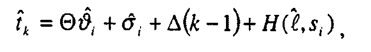
단계 420에서, 상기 프로세스는 그 다음 수신기가 제1 샘플을 생성한 시간(![]()
![]()
![]()
![]()
![]()
![]()
시간(![]()
![]()
![]()
![]()
![]()
![]()
![]()
![]()
![]()
![]()
![]()
![]()
![]()
![]()
그 다음, 상기 프로세스는 근사 제1 샘플 시간(![]()
![]()
![]()
![]()
![]()
![]()
![]()
![]()
![]()
![]()
![]()
![]()
![]()
![]()
근사 전송 시간에서의 선택된 위성의 위치를 계산한 후에, 상기 프로세스는 선택된 위성이 GPS-위성 리스트에 있는 최종 GPS 위성인지 여부를 결정한다(단계 440). 그렇지 않은 경우, 상기 프로세스는 이 리스트로부터 다른 GPS 위성을 선택하고(단계 445), 새로이 선택된 위성의 근사 위치를 결정하기 위하여 단계 415 내지 435를 반복한다. 그렇지 않은 경우, 상기 프로세스는 모든 GPS 위성들이 최초 생성된 샘플이 되는 신호들을 전송한 근사 시간에서의 모든 GPS 위성들의 위치를 계산한 것으로 결정한다. 그러므로, 상기 프로세스는 종료한다.After calculating the position of the selected satellite at the approximate transmission time, the process determines whether the selected satellite is the last GPS satellite in the GPS-satellite list (step 440). Otherwise, the process selects another GPS satellite from this list (step 445) and repeats
B. 상공에 있는 위성들의 식별B. Identification of satellites in the air
모든 GPS 위성들의 위치를 식별한 후에, 상기 프로세스(200)는 현재 "상공에 있는" 위성들을 식별한다(단계 210). 몇몇 실시예들에 있어서, 상기 프로세스(200)는 그들이 근사 위치(![]()
![]()
그러므로, 이들 실시예들에 있어서, 상기 프로세스(200)는 각 위성(i)을 검사하고 상기 위성이 근사 위치(![]()
![]()
![]()
![]()
![]()
![]()
이러한 지정 기준은 본질적으로 근사 위치 벡터(![]()
![]()
![]()
![]()
도 5는 이러한 지정 기준을 도시한다. 이 도면은 지구(510) 상의 근사 위치(![]()
![]()
![]()
![]()
![]()
![]()
![]()
![]()
다른 한편, 상기 위성(520)은 상기 위치(![]()
![]()
![]()
![]()
![]()
![]()
도 6은 상공에 있는 위성들을 식별하기 위하여 상술된 접근법을 이용하는 프로세스(600)를 도시한다. 이 프로세스는 본 발명의 몇몇 실시예들에서 단계 210에서 프로세스(200)에 의해 사용된다. 도 6에 도시된 바와 같이, 상기 프로세스(600)는 처음에 자신과 근사 위치 벡터(![]()
![]()
다음에, 상기 프로세스(600)는 GPS 위성들의 리스트로부터 하나의 GPS 위성을 선택한다(단계 610). 그 다음, 상기 프로세스는 단계 205에서 계산된, 선택된 위성의 근사 위치 벡터(si)와 근사 위치 벡터(![]()
![]()
단계 620에서, 상기 프로세스(600)는 단계 615에서 산출된 내적이 단계 605에서 산출된 내적보다 크거나 같은지 여부를 결정한다. 그렇지 않은 경우, 상기 프로세스는 후술되는 단계 630으로 진행한다. 그렇지 않은 경우, 상기 프로세스는 단계 610에서 선택된 위성을 상공에 있는 위성으로 지정하고(단계 625), 단계 630으로 진행한다.In
단계 630에서, 상기 프로세스는 GPS 위성들의 리스트에 있는 모든 GPS 위성들을 검사했는지 여부를 결정한다. 그렇지 않은 경우, 상기 프로세스는 이 리스트로부터 다른 GPS 위성을 선택하기 위하여 단계 610으로 되돌아 가서, 새로이 선택된 위성이 상공에 있는 위성인지 아닌지를 결정하기 위하여 상술된 동작들을 반복한다.In
일단, 상기 프로세스가 모든 GPS 위성들을 검사했다고 결정(단계 630)한 경우, 상기 프로세스는 종료한다. 전형적으로, 상기 프로세스(600)가 종료할 때에는, 이 프로세스는 상공에 있는 위성들로서 GPS 위성들의 정수(N)를 식별한다. 이하 설명에서, 이들 지정된 상공에 있는 위성들은 정수(1 내지 N)로 표시된다.Once the process determines that all GPS satellites have been checked (step 630), the process ends. Typically, when the
C. 위성 도플러 계산.C. Satellite Doppler Calculation.
상공의 위성들을 식별한 후에, 프로세스(200)는 상공의 각 위성에 대한 부가적인 도플러 편이 값을 계산한다(단계 215) . 도 7은 상기 도플러 편이 값을 계산하는 실시예들에서 프로세스(200)에 의해 사용되는 프로세스(700)를 도시한다. 도 7에 도시한 바와 같이, 프로세스(700)는 (210)에서 식별된 상공의 GPS 위성들 중에서 하나를 선택함으로써 초기에 시작한다(단계 705).After identifying the satellites above, the
위성에 대한 부가적인 도플러 편이 값 ![]()
![]()
![]()
![]()
도 8은 근사 위치 ![]()
![]()
![]()
![]()
![]()
![]()
![]()
![]()
![]()
![]()
위성으로부터 상기 근사 위치까지의 방향은 벡터 ![]()
![]()
![]()
![]()
![]()
![]()
![]()
![]()
![]()
![]()

그러므로, 710에서 프로세스(700)는 상기 근사 위치 ![]()
![]()
715에서, 상기 프로세스는 아래의 수학식 (4)를 사용함으로써 선택된 위성 ![]()
![]()
![]()
![]()

상기 수학식에 있어서, ![]()
![]()
![]()
![]()
720에서, 상기 프로세스는 상공의 GPS 위성의 리스트에서 모든 상공의 GPS 위성에 대한 부가적인 도플러 편이 값을 생성했는지의 여부를 결정한다. 만일 그렇지 않다면, 상기 프로세스는 상기 리스트에서 또 다른 GPS 위성을 선택하기 위해 705로 리턴하고, 새롭게 선택된 위성에 대한 부가적인 도플러 편이 값을 생성하기 위해 전술한 동작을 반복한다. 일단 상기 프로세스가 모든 상공의 GPS 위성에 대해 부가적인 도플러 편이 값을 생성했다고 결정하면, 상기 프로세스는 종료한다.At 720, the process determines whether additional Doppler shift values have been generated for all upstream GPS satellites in the list of upcoming GPS satellites. If not, the process returns to 705 to select another GPS satellite from the list, and repeats the above operation to generate additional Doppler shift values for the newly selected satellites. Once the process determines that it has generated additional Doppler shift values for all GPS satellites above, the process ends.
D. 영역 식별D. Identify Zone
모든 상공의 위성들에 대한 부가적인 도플러 편이를 계산한 후에, 프로세스(200)는 근사 위치 주변의 영역을 식별한다(단계 220). 이하에 더 상세하게 설명되는 바와 같이, 상기 프로세스는 GPS 수신기의 위치를 추정하기 위해 상기 영역을 탐색한다. After calculating the additional Doppler shift for all satellites above,
도 9-11은 프로세스(200)가 본 발명의 다른 실시예에서 탐색한 3가지 타입의 영역을 도시한다. 도 9에 도시된 바와 같이, 어떤 실시예에 있어서, 상기 프로세스는 근사 위치 ![]()
![]()
![]()
![]()
![]()
![]()
도 10은 상기 프로세스가 근사 위치 ![]()
![]()
![]()
![]()
![]()
![]()
어떤 실시예들은 상기 영역에 대한 저장 구조 정보에서 검색함으로써 상기 근사 위치 주변의 영역들(예; 원형, 원통형, 또는 구형 영역들)을 식별한다. 예를 들면, 어떤 실시예들은 각 기지국 타워(tower)(즉, 각각의 잠재적인 근사 위치)를 둘러싸는 영역에 대한 정보를 저장한다. 위치-결정 서버(300)가 특정한 기지국에서 신호를 수신할 때, 이들 실시예들은 상기 특정한 기지국 타워의 위치를 둘러싸는 영역에 대한 정보를 저장 구조에서 검색한다. 어떤 실시예들은 상기 기지국 타워 식별을 사용함으로써 저장 구조를 인덱싱한다(즉, 저장 구조에서 위치 및 영역 정보를 탐색하고 검색한다). Some embodiments identify areas (eg, circular, cylindrical, or spherical areas) around the approximate location by searching in the storage structure information for the area. For example, some embodiments store information about the area surrounding each base station tower (ie, each potential approximate location). When location-determining
E. GPS-수신기 위치의 추정E. Estimation of GPS-Receiver Location
GPS 수신기에 대한 영역을 식별한 후에, 프로세스(200)는 상기 영역의 GPS 수신기의 위치를 추정한다(단계 225). 이하에 개시되는 실시예들은 상기 영역 내의 다수의 후보 위치를 초기에 선택함으로써 GPS-수신기의 위치를 추정한다. 각각의 특정하게 선택된 위치에 대해서, 이들 실시예들은 GPS 기준 데이터와 상기 수신기가 상기 특정 위치에서 수신할 것이 예측되는 신호의 샘플 사이의 유사성을 정량화하는 거리 함수 M을 계산한다. 그 다음, 이들 실시예들은 GPS 수신기의 위치로서 가장 좋게 계산된 미터 값으로 된 위치를 식별한다. After identifying the region for the GPS receiver, the
어떤 실시예들은 상기 영역 내의 일 세트의 후보 위치들에서 뿐만이 아니라 다른 미지의 매개변수에 대한 후보 세트에서도 상기 미터 값 M을 계산한다. 예를 들면, 어떤 실시예들은 다음의 5개 미지 매개변수의 함수로서 미터 값 M을 계산한다: (1) ![]()
![]()
![]()
![]()
![]()
![]()
![]()
![]()
![]()
![]()
본 명세서에 있어서, "햇(hat)"은 변수 값이 변수 값의 범위 내의 후보 값인 것을 나타내는 변수 상에 놓인다. 또한, 미터 값 M은 수신기 클록의 부정확성을 고려하기 위해 변수 1차-샘플 시간의 함수로서 계산된다. 부가하여, 전술한 바와 같이, 미터 값 M은 수신기 클록의 편차 ![]()
![]()
![]()
![]()
어떤 실시예들은 각각의 변수 ![]()
![]()
![]()
![]()
![]()
![]()
![]()
![]()
![]()
![]()
![]()
![]()
![]()
![]()
![]()
![]()
각 가설 ![]()
![]()
![]()
![]()
![]()
![]()
![]()
![]()
![]()
![]()
![]()
![]()
![]()
![]()
각 가설 ![]()
![]()
![]()
![]()
![]()
![]()
![]()
![]()
각 가설 ![]()
![]()
![]()
![]()
![]()
![]()
![]()
![]()
본 발명의 다른 실시예들은 다른 메트릭 함수들을 사용한다. 어떤 실시예들은 수신된 GPS 기준 신호와 가설 ![]()
![]()
![]()
![]()
![]()
![]()

상기 수학식에서, 변수 ![]()
![]()
![]()
![]()
![]()
![]()
![]()
![]()
![]()
![]()
가설 ![]()
![]()
![]()
![]()

다른 접근법 하에서, 생성된 차이 값은 수신된 신호와 가설이 진실이면 GPS 수신기가 수신하는 것이 기대되는 신호 사이의 차이를 정량화한다. 가장 좋은 차이 값은 가장 작은 값이다. 그러므로, 차감 거리를 계산하는 실시예들은 상기 메트릭을 최소화하거나 또는 상기 거리를 작게 하는 가설을 찾기 위해 후보 공간을 통해 탐색한다.Under another approach, the generated difference value quantifies the difference between the received signal and the signal the GPS receiver is expected to receive if the hypothesis is true. The best difference is the smallest. Therefore, embodiments of calculating subtraction distances search through candidate spaces to find hypotheses that minimize the metric or reduce the distance.
어떤 실시예들은 그들 자신의 거리 함수로서 측정-가능성(log-likelihood) 비율을 사용한다. 예를 들면, 이하에 개시되는 실시예들은 아래와 같은 수학식 (6)에 의해 제공되는 측정-가능성 비율을 사용한다.Some embodiments use a log-likelihood ratio as their own distance function. For example, the embodiments disclosed below use the measure-likelihood ratio provided by Equation (6) below.

상기 함수를 최소화하는 것은 수학식 (5)의 차감 함수 ![]()
![]()
![]()
![]()
![]()
![]()
![]()
![]()
![]()
![]()
![]()
![]()
![]()
![]()
![]()
![]()
![]()
![]()
![]()
![]()
![]()
![]()
가설 ![]()
![]()
![]()
![]()

다른 접근법 하에서, 가장 좋게 생성된 측정-가능성 비율은, 아래 수학식 (7)에 의해 나타난 바와 같이, 가장 큰 값이다.Under another approach, the best generated measurement-likelihood ratio is the largest value, as represented by equation (7) below.

그러므로, 측정-가능성 비율을 계산하는 실시예들은, 상기 값을 최대화하거나 또는 상기 값을 크게 만드는 후보 세트를 찾기 위해 후보 공간을 통해 탐색한다. 최대 측정-가능성 비율로 되는 가설 ![]()
![]()
최대화 프로세스는 아래에 나타난 바와 같이 2개의 별개의 최대화 프로세스로 분할될 수 있다. The maximization process can be divided into two distinct maximization processes as shown below.

그러므로, 어떤 실시예들은 2개 루프에서 상기 최대화 동작을 수행한다:(1) ![]()
![]()
![]()
![]()
![]()
![]()
![]()
![]()
1. 기준 가정 신호 모델링 1. Reference hypothesis signal modeling
상술한 바와 같이, 위치-결정 서버(300)는 기준 GPS 수신기에서 GPS 시간의 함수로서 각 위성의 네비게이션 비트들을 수신한다. 따라서, 이 서버는 각 위성에 의해 송신된 신호를 재생할 수 있다. 시간 ![]()
![]()
![]()
![]()

상기 수학식에서 아래의 수학식은 위성 ![]()
![]()

수학식 (9) 및 (10)에서, ![]()
![]()
![]()
![]()
![]()
![]()
![]()
![]()
![]()
![]()
GPS 수신기는 N 상공의 위성에서의 신호와 잡음의 선형 조합을 수신한다. 위성 ![]()
![]()
![]()
![]()
![]()
![]()

샘플링 전에, 수신기는 수신된 신호 상에서 대역통과 필터링과 믹싱을 수행한다. 상기 두 동작은 선형 동작이다. 그러므로, 이들 동작은 다른 위성에 근원하는 수신된 신호의 부분 상에서 개별적으로 동작한다. 믹싱의 목적은 ![]()
![]()
![]()
![]()
![]()
![]()
![]()
![]()
![]()
![]()
이러한 이유들 때문에, 항
![]()
![]()
대역통과 필터링의 효과는 기본대역 전송된 신호 ![]()
![]()
![]()
![]()
![]()
![]()
![]()
![]()
요약하자면, 위성 ![]()
![]()

![]()
![]()
![]()
![]()
상술한 설명에 따라 아래의 식들은, (1) 후보값들의 가정된 집합에 대해 가정된 기준 신호 ![]()
![]()
● 네비게이션 비트들과 PRN 코드:Navigation bits and PRN code:

● 저대역 통과 필터링:● Low pass filtering:

● 시간 이동 및 코사인(cosine) 변조: Time shift and cosine modulation:

● 발생된 가정의 신호에 대한 위성 ![]()
![]()

● 여러 위성들의 기여들을 가산함:Add the contributions of several satellites:

● 샘플링:● Sampling:


● 가능성 계산:● Probability calculation:


어떤 실시예들은, 먼저, 모든 위성들의 발생된 가정 신호들 ![]()
![]()
![]()
![]()
![]()
![]()
![]()
![]()
![]()
![]()
![]()
![]()
![]()
![]()
그러나, 이하의 서브 섹션 3에 기술된 실시예들은, 각각의 발생된 가정 신호 (즉, 각 ![]()
![]()
![]()
![]()
![]()
![]()
![]()
![]()
![]()
![]()
![]()
![]()
상술하고 있는 ![]()
![]()
![]()
![]()
![]()
![]()
2. 측정-가능성-비율-산출 프로세스2. Measurement-probability-ratio-calculation process
상술한 바와 같이, 어떤 실시예들은 GPS-수신기 위치를, 상술한 수학식 21에서 나타낸 측정-가능성 비율을 최대화시키는 가정 ![]()
![]()
![]()
![]()
![]()
![]()
![]()
![]()
![]()
![]()
도 12는 그러한 집약된 루프 방식을 사용한 프로세스(1200)를 도시한 것이다. 프로세스(1200)는 변수 ![]()
![]()
![]()
![]()
![]()
![]()
![]()
![]()
후보 위치 벡터들 ![]()
![]()
![]()
![]()
![]()
![]()
![]()
![]()
![]()
![]()
![]()
![]()
![]()
![]()
![]()
![]()
![]()
![]()
![]()
![]()
이하의 서브-섹션 3은, 최적 파워 및 위상 벡터들을 얻기 위해 파워 및 위상 후보 공간을 모두 검색하지 않고 내부 루프를 수행하는 한 방법을 기술하고 있다. 이하에서 더 기술된 것과 같이, 이러한 방법은 측정-가능성 비율을 직교 함수(quadratic function)로 만드는 두 개의 새로운 변수들을 도입하여, 그 새 변수들에 대한 최적값들을 얻도록 이 직교 함수의 도함수(derivative)를 0으로 놓는다. 이들 최적값들을 위해, 다음으로, (1) GPS 신호 스냅샷, 및 (2) 현재의 가정이 맞고 잡음이 없을 때 수신기가 수신할 가정 신호의 상응하는 스냅샷에 기반하여 측정-가능성 비율 L이 산출된다.
선택된 ![]()
![]()
![]()
![]()
![]()
![]()
![]()
![]()
![]()
![]()
1225 단계에서, 그 선택된 후보들에 대한 측정-가능성 비율 L이 ![]()
![]()
![]()
![]()
![]()
![]()
![]()
![]()
![]()
![]()
1235 단계에서, 차례로 나열된 후보 위치 벡터들 ![]()
![]()
![]()
![]()
![]()
![]()
![]()
![]()
3. 내부 루프(inner loop) 수행하기3. Inner loop
수학식 8의 집약된 루프 프로세스의 내부 루프를 수행하는 한가지 방식이 지금부터 기술될 것이다(단계 1220). 1200 프로세스가 1220 단계에 도달하는 시기에, 후보들 ![]()
![]()
어떤 실시예들은 상술한 수학식 21로부터 도출된 수학식의 집합을 이용해 내부 루프를 수행한다. 이 수학식의 집합은 수학식 26-32를 포함하는데, 이들은 이하에서 설명될 것이다. 그러나, 이들 수학식을 설명하기에 앞서, 이들 수학식들의 도출 과정이 첫머리에 설명될 것이다.Some embodiments perform an inner loop using a set of equations derived from equation 21 described above. This set of equations includes Equations 26-32, which will be described below. However, prior to explaining these equations, the derivation process of these equations will be described first.
a. 수학식 26-32의 도출a. Derivation of Equations 26-32
수학식 26-32를 도출하기 위해, 새로운 변수들의 집합이 도입된다. 이 변수들은 다음과 같다: To derive Equations 26-32, a new set of variables is introduced. These variables are as follows:


이 변수들은 그들이 이 새로운 변수들로 된 직교 함수로 수학식 21을 줄이기 때문에 도입된 것이다. 이 직교 함수는 자신의 도함수를 0으로 놓고 나서, 그 결과에 따른 미지의 2N으로 된 2N차 등식들로 된 시스템을 풀어서 최적화될 수 있다. 그러므로, 이 직교 함수는 파워 레벨과 캐리어 위상에 대한 측정-가능성 비율을, 파워 및 위상 후보 공간을 끝까지 검색하지 않고도 최대화시키는 방법을 제공한다. These variables were introduced because they reduced Eq. 21 to an orthogonal function of these new variables. This orthogonal function can be optimized by setting its derivative to zero, then solving for a system of unknown 2N quadratic equations with the result. Therefore, this orthogonal function provides a method of maximizing the measurement-likelihood ratio for power level and carrier phase without searching through the power and phase candidate spaces to the end.
구체적으로 설명하면, 수학식 15의 변수 ![]()
![]()
![]()
![]()
![]()
![]()


시간에 대한 종속성을 보다 명확히 하기 위해, 기호가 바뀔 수 있다. (통상적으로 매 1ms 마다 반복되는 PRN 코드를) 반복하기 전에 PRN 코드의 길이가 될 ![]()
![]()
![]()
![]()
![]()
![]()
![]()
![]()
![]()
![]()
![]()
![]()
![]()
![]()
![]()
![]()
다음과 같은 I 및 Q 성분을 정의함으로써, By defining the following I and Q components:


측정-가능성 비율이 수학식 30에 의해 양호하게 근사화될 수 있다.The measure-likelihood ratio can be well approximated by equation (30).

수학식 30은 변수 ![]()
![]()
![]()
![]()
![]()
![]()


이들 변수들 ![]()
![]()
![]()
![]()
b. 측정-가능성 비율의 산출b. Calculation of the measure-likelihood ratio
후보 ![]()
![]()
![]()
![]()
![]()
![]()
![]()
![]()
![]()
![]()
이 분야의 당업자라면, 상술한 실시예들이 여러 장점들을 가진다는 것을 알 수 있을 것이다. 예를 들어, 이들 실시예들은 세 개 이상의 위성들로부터 강력한 신호를 필요로 하는 삼각 측량 동작을 수행하지 않는다. 그보다는, 영향을 미칠 수 있는 모든 위성들에 대한 데이터를 분석함으로써 자신들의 위치 검출 동작을 수행한다.Those skilled in the art will appreciate that the embodiments described above have several advantages. For example, these embodiments do not perform triangulation operations requiring strong signals from three or more satellites. Rather, they perform their position detection by analyzing data for all satellites that may be affected.
모든 가능한 위성들의 기여를 분석하는 것은 이 실시예들의 감도를 향상시킨다. 이러한 향상된 감도는 위성 신호가 약해지는 환경(가령, 실내 또는 숲속)에서 특히 유익한 것이 된다. 즉, 이 실시예들은 전통적 GPS 기술에 비해 신호 감쇠를 훨씬 잘 감당할 수 있으며, 따라서 전통적 GPS 기술이 실패하도록 야기하는 환경에서 위치 결정을 수행할 수 있다. Analyzing the contribution of all possible satellites improves the sensitivity of these embodiments. This enhanced sensitivity is particularly beneficial in environments where satellite signals are weakened (eg indoors or in the woods). That is, these embodiments can tolerate signal attenuation much better than traditional GPS techniques, and thus perform location determination in an environment that causes traditional GPS techniques to fail.
위성 신호가 크게 감쇠하지 않는 환경에서도, 모든 가능한 위성들의 기여를 분석하는 것은, 이 실시예들이 전통적 GPS 기술들에 대해 비교 가능한 결과를 얻도록 하기 위해 고려할 필요가 있는 데이터량(즉, 샘플들의 개수)을 감소시킨다는 점에서 유리한 것이다. 이러한 분석은 GPS 위성들의 코드 위상들을 함께 고려한다. 따라서, 그러한 분석은 불가능한 코드 위상 후보 조합들을 고려하지 않을 것이므로, 통계학적으로 보다 효율적일 것이다.Even in an environment where the satellite signal does not significantly attenuate, analyzing the contributions of all possible satellites suggests that the amount of data (ie, the number of samples) that these embodiments need to consider in order to obtain a comparable result for traditional GPS techniques. It is advantageous in that it decreases. This analysis takes into account the code phases of the GPS satellites. Thus, such an analysis will not consider impossible code phase candidate combinations, and therefore will be statistically more efficient.
또, 모든 가능한 위성들의 기여를 분석하는 것은 위성간 간섭이 위치 결정 계산으로부터 무시될 수 있게 하고, 그에 따라, 위치가 보다 정밀하게 산출될 수 있게 한다. 예를 들어, 측정-가능성 비율 수학식 20 및 21에서, 위성간 간섭은 그들 수학식의 두번째 항에 대응하는데, 그 항은 수학식들의 첫번째 항에서 감산된다; 이 수학식들에서, 첫번째 항들은 수신된 GPS 기준 데이터와 가정한 기준 신호들간 내적을 제공한다.In addition, analyzing the contribution of all possible satellites allows the inter-satellite interference to be neglected from the positioning calculations, thus allowing the position to be calculated more precisely. For example, in the measurement-likelihood ratio equations 20 and 21, the inter-satellite interference corresponds to the second term of those equations, which term is subtracted from the first term of the equations; In these equations, the first terms provide the dot product between the received GPS reference data and the hypothesized reference signals.
본 발명은 여러가지 상세한 설명들을 참조해 기술되었으나, 이 분야의 당업자라면 본 발명이 그 개념으로부터 벗어나지 않고 다른 특정한 형태로 실시될 수 있음을 인지할 것이다. 예를 들어, 상술한 바와 같이, 위치-결정 프로세스(220)는 (1) GPS 수신기를 차단하는 영역 내에서 여러 위치들을 선택하고, (2) 각각의 특정 선택 위치에 대해, GPS 기준 데이터와, 수신기가 특정 선택 위치에서 수신 예측할 수 있는 신호 사이의 유사성을 정량화하는 미터 값을 산출하고, (3) 계산식에 기반해 GPS 수신기의 위치를 예측한다.Although the present invention has been described with reference to various details, those skilled in the art will recognize that the present invention may be embodied in other specific forms without departing from the concept. For example, as described above, the location-
그러나, 당업자라면 다른 실시예들이 다른 방식으로 GPS 수신기 위치를 예측한다는 것을 알 수 있을 것이다. 예를 들어, 한 실시예에서는 한번에 한 위치를 선택하고, 그 선택된 위치에 대해 미터 값을 산출하며, 산출된 미터 값을 임계값과 비교한다. 산출된 미터 값이 임계값 보다 양호하면, 이 실시예는 그 선택된 위치를 예상 GPS 수신기 위치로서 식별한다. 그렇지 않으면, 이 실시예는 위치들 가운데 하나가 임계값보다 양호하게 될 때까지 GPS 수신기를 포함하는 영역 내에서 계속해서 위치를 선택한다. 다른 실시예들에서는 임계값을 상이하게 정의한다. 어떤 실시예들에서, 이 값은 환경에 좌우되지만, 또 다른 실시예에서 이 값은 수신된 신호에 관한 어떤 통계값에 좌우된다.However, one skilled in the art will recognize that other embodiments predict GPS receiver location in different ways. For example, one embodiment selects one location at a time, calculates a meter value for that selected location, and compares the calculated meter value with a threshold. If the calculated meter value is better than the threshold, this embodiment identifies the selected location as the expected GPS receiver location. Otherwise, this embodiment continues to select a location within the area containing the GPS receiver until one of the locations is better than the threshold. In other embodiments the thresholds are defined differently. In some embodiments, this value depends on the environment, but in another embodiment this value depends on some statistical value regarding the received signal.
또, 상술한 실시에들이 상용 GPS 주파수를 사용하고 있고, 다른 실시예들은 군사용 GPS 주파수를 사용하고 있지만, 또 다른 실시예에서는 군사용과 상용 주파수들을 모두 사용한다. 따라서, 이 분야의 당업자라면 본 발명이 이전의 세부적 예시들에 의해 한정되어서는 안되고, 그보다는 첨부된 청구항들에 의해 한정되어야 함을 이해할 수 있을 것이다.Further, while the above embodiments use commercial GPS frequencies, while other embodiments use military GPS frequencies, yet other embodiments use both military and commercial frequencies. Thus, it will be apparent to one skilled in the art that the present invention should not be limited by the previous detailed examples, but rather by the appended claims.
Claims (45)
Applications Claiming Priority (3)
| Application Number | Priority Date | Filing Date | Title |
|---|---|---|---|
| US09/782,648 US6525687B2 (en) | 2001-02-12 | 2001-02-12 | Location-determination method and apparatus |
| US09/782,648 | 2001-02-12 | ||
| PCT/US2002/003899 WO2003001232A2 (en) | 2001-02-12 | 2002-02-11 | Location-determination method and apparatus |
Publications (2)
| Publication Number | Publication Date |
|---|---|
| KR20030075193A KR20030075193A (en) | 2003-09-22 |
| KR100657444B1 true KR100657444B1 (en) | 2007-02-28 |
Family
ID=25126735
Family Applications (1)
| Application Number | Title | Priority Date | Filing Date |
|---|---|---|---|
| KR1020037010635A KR100657444B1 (en) | 2001-02-12 | 2002-02-11 | Location-determination Method and Apparatus |
Country Status (5)
| Country | Link |
|---|---|
| US (1) | US6525687B2 (en) |
| EP (1) | EP1565762A2 (en) |
| KR (1) | KR100657444B1 (en) |
| CN (1) | CN100578252C (en) |
| WO (1) | WO2003001232A2 (en) |
Cited By (2)
| Publication number | Priority date | Publication date | Assignee | Title |
|---|---|---|---|---|
| CN106932789A (en) * | 2017-04-26 | 2017-07-07 | 易微行(北京)科技有限公司 | The determination methods and automobile of a kind of mobile device mobile status |
| KR20220094883A (en) * | 2020-12-29 | 2022-07-06 | 심광보 | Apparatus and method for providing golf green informaion using of location based service |
Families Citing this family (44)
| Publication number | Priority date | Publication date | Assignee | Title |
|---|---|---|---|---|
| US10361802B1 (en) | 1999-02-01 | 2019-07-23 | Blanding Hovenweep, Llc | Adaptive pattern recognition based control system and method |
| US8352400B2 (en) | 1991-12-23 | 2013-01-08 | Hoffberg Steven M | Adaptive pattern recognition based controller apparatus and method and human-factored interface therefore |
| US7904187B2 (en) | 1999-02-01 | 2011-03-08 | Hoffberg Steven M | Internet appliance system and method |
| US8255149B2 (en) | 1999-07-12 | 2012-08-28 | Skybitz, Inc. | System and method for dual-mode location determination |
| US20040143392A1 (en) | 1999-07-12 | 2004-07-22 | Skybitz, Inc. | System and method for fast acquisition reporting using communication satellite range measurement |
| JP2003075524A (en) * | 2001-08-31 | 2003-03-12 | Denso Corp | Mobile communication terminal device, program and position server therefor |
| US8126889B2 (en) * | 2002-03-28 | 2012-02-28 | Telecommunication Systems, Inc. | Location fidelity adjustment based on mobile subscriber privacy profile |
| US6650288B1 (en) * | 2002-05-23 | 2003-11-18 | Telecommunication Systems | Culled satellite ephemeris information for quick assisted GPS location determination |
| US7463979B2 (en) * | 2003-08-28 | 2008-12-09 | Motorola, Inc. | Method and apparatus for initializing an approximate position in a GPS receiver |
| US8489874B2 (en) * | 2004-03-17 | 2013-07-16 | Telecommunication Systems, Inc. | Encryption STE communications through private branch exchange (PBX) |
| US8239669B2 (en) * | 2004-03-17 | 2012-08-07 | Telecommunication Systems, Inc. | Reach-back communications terminal with selectable networking options |
| US7761095B2 (en) * | 2004-03-17 | 2010-07-20 | Telecommunication Systems, Inc. | Secure transmission over satellite phone network |
| US8280466B2 (en) * | 2004-03-17 | 2012-10-02 | Telecommunication Systems, Inc. | Four frequency band single GSM antenna |
| US7629926B2 (en) * | 2004-10-15 | 2009-12-08 | Telecommunication Systems, Inc. | Culled satellite ephemeris information for quick, accurate assisted locating satellite location determination for cell site antennas |
| US7411546B2 (en) * | 2004-10-15 | 2008-08-12 | Telecommunication Systems, Inc. | Other cell sites used as reference point to cull satellite ephemeris information for quick, accurate assisted locating satellite location determination |
| US6985105B1 (en) * | 2004-10-15 | 2006-01-10 | Telecommunication Systems, Inc. | Culled satellite ephemeris information based on limiting a span of an inverted cone for locating satellite in-range determinations |
| US7113128B1 (en) * | 2004-10-15 | 2006-09-26 | Telecommunication Systems, Inc. | Culled satellite ephemeris information for quick, accurate assisted locating satellite location determination for cell site antennas |
| US7825780B2 (en) * | 2005-10-05 | 2010-11-02 | Telecommunication Systems, Inc. | Cellular augmented vehicle alarm notification together with location services for position of an alarming vehicle |
| US20070075848A1 (en) * | 2005-10-05 | 2007-04-05 | Pitt Lance D | Cellular augmented vehicle alarm |
| US20070164553A1 (en) * | 2006-01-17 | 2007-07-19 | Dov Katz | Coloring book with embedded inwardly foldable stencils |
| US7471236B1 (en) | 2006-03-01 | 2008-12-30 | Telecommunication Systems, Inc. | Cellular augmented radar/laser detector |
| US7899450B2 (en) | 2006-03-01 | 2011-03-01 | Telecommunication Systems, Inc. | Cellular augmented radar/laser detection using local mobile network within cellular network |
| US9167553B2 (en) | 2006-03-01 | 2015-10-20 | Telecommunication Systems, Inc. | GeoNexus proximity detector network |
| FI118394B (en) * | 2006-05-26 | 2007-10-31 | Savcor One Oy | A system and method for locating a GPS device |
| US8493267B2 (en) | 2006-11-10 | 2013-07-23 | Qualcomm Incorporated | Method and apparatus for position determination with extended SPS orbit information |
| US8948778B2 (en) * | 2007-09-11 | 2015-02-03 | Qualcomm Incorporated | Delayed radio resource signaling in a mobile radio network |
| US20090153397A1 (en) * | 2007-12-14 | 2009-06-18 | Mediatek Inc. | Gnss satellite signal interference handling method and correlator implementing the same |
| US8803737B2 (en) * | 2008-02-29 | 2014-08-12 | Apple Inc. | Location determination |
| US8213389B2 (en) * | 2008-04-15 | 2012-07-03 | Apple Inc. | Location determination using formula |
| EP2347395A4 (en) | 2008-10-14 | 2016-11-02 | Telecomm Systems Inc | Location based proximity alert |
| US8892128B2 (en) * | 2008-10-14 | 2014-11-18 | Telecommunication Systems, Inc. | Location based geo-reminders |
| US8259010B2 (en) * | 2009-10-14 | 2012-09-04 | Qualcomm Incorporated | Qualifying coarse position injection in position determination systems |
| US8336664B2 (en) | 2010-07-09 | 2012-12-25 | Telecommunication Systems, Inc. | Telematics basic mobile device safety interlock |
| WO2012005769A1 (en) | 2010-07-09 | 2012-01-12 | Telecommunication Systems, Inc. | Location privacy selector |
| US8384584B2 (en) | 2010-12-10 | 2013-02-26 | Roundtrip Llc | Reduced computation communication techniques for location systems |
| US8466835B2 (en) | 2011-05-13 | 2013-06-18 | The Charles Stark Draper Laboratory, Inc. | Systems and methods for clock correction |
| CN102209384B (en) * | 2011-05-19 | 2013-12-25 | 北京邮电大学 | Quick positioning method and device |
| US8649806B2 (en) | 2011-09-02 | 2014-02-11 | Telecommunication Systems, Inc. | Aggregate location dynometer (ALD) |
| US8688174B2 (en) | 2012-03-13 | 2014-04-01 | Telecommunication Systems, Inc. | Integrated, detachable ear bud device for a wireless phone |
| US9057774B2 (en) * | 2012-04-05 | 2015-06-16 | Raytheon Company | Position determination using local time difference |
| CN103837877B (en) * | 2012-11-21 | 2016-03-09 | 安凯(广州)微电子技术有限公司 | A kind of method and apparatus of satellite identification |
| US20160050030A1 (en) * | 2012-11-29 | 2016-02-18 | The Board Of Trustees Of The University Of Illinois | System and method for communication with time distortion |
| US9671500B1 (en) * | 2015-12-22 | 2017-06-06 | GM Global Technology Operations LLC | Systems and methods for locating a vehicle |
| CN108535744B (en) * | 2017-03-03 | 2021-05-04 | 清华大学 | Intelligent forwarding type navigation deception method and equipment based on aircraft |
Family Cites Families (4)
| Publication number | Priority date | Publication date | Assignee | Title |
|---|---|---|---|---|
| ATE222000T1 (en) * | 1996-04-25 | 2002-08-15 | Sirf Tech Inc | SPREAD SPECTRUM RECEIVER WITH MULTIBIT CORRELATION |
| US5926761A (en) * | 1996-06-11 | 1999-07-20 | Motorola, Inc. | Method and apparatus for mitigating the effects of interference in a wireless communication system |
| US5884215A (en) * | 1997-01-31 | 1999-03-16 | Motorola, Inc. | Method and apparatus for covariance matrix estimation in a weighted least-squares location solution |
| US5940035A (en) * | 1997-03-27 | 1999-08-17 | Innovative Solutions & Support Inc. | Method for calibrating aircraft altitude sensors |
-
2001
- 2001-02-12 US US09/782,648 patent/US6525687B2/en not_active Expired - Lifetime
-
2002
- 2002-02-11 WO PCT/US2002/003899 patent/WO2003001232A2/en not_active Application Discontinuation
- 2002-02-11 KR KR1020037010635A patent/KR100657444B1/en not_active IP Right Cessation
- 2002-02-11 CN CN02807470A patent/CN100578252C/en not_active Expired - Fee Related
- 2002-02-11 EP EP02773144A patent/EP1565762A2/en not_active Withdrawn
Cited By (3)
| Publication number | Priority date | Publication date | Assignee | Title |
|---|---|---|---|---|
| CN106932789A (en) * | 2017-04-26 | 2017-07-07 | 易微行(北京)科技有限公司 | The determination methods and automobile of a kind of mobile device mobile status |
| KR20220094883A (en) * | 2020-12-29 | 2022-07-06 | 심광보 | Apparatus and method for providing golf green informaion using of location based service |
| KR102429533B1 (en) * | 2020-12-29 | 2022-08-04 | 심광보 | Apparatus for providing golf green informaion using of location based service |
Also Published As
| Publication number | Publication date |
|---|---|
| EP1565762A2 (en) | 2005-08-24 |
| WO2003001232A8 (en) | 2005-06-30 |
| WO2003001232A2 (en) | 2003-01-03 |
| KR20030075193A (en) | 2003-09-22 |
| US6525687B2 (en) | 2003-02-25 |
| US20020145557A1 (en) | 2002-10-10 |
| CN100578252C (en) | 2010-01-06 |
| CN1636146A (en) | 2005-07-06 |
Similar Documents
| Publication | Publication Date | Title |
|---|---|---|
| KR100657444B1 (en) | Location-determination Method and Apparatus | |
| KR100657445B1 (en) | Location-determination method and apparatus | |
| EP2309287B1 (en) | Improvements in radio positioning systems | |
| EP1676144B1 (en) | Method and apparatus for performing signal correlation using historical correlation data | |
| EP2469302A1 (en) | Method for open loop tracking GPS signals | |
| JP2004501352A (en) | Signal detector and method employing a coherent accumulation system for correlating non-uniform and discrete sample segments | |
| KR100937130B1 (en) | Method and apparatus for performing signal correlation using historical correlation data | |
| CN1987515B (en) | Method and system for realizing GPS positioning under weak signal environment | |
| EP1581820A1 (en) | Method and apparatus for performing timing synchronization | |
| EP1160582A2 (en) | Method and device for determining the phase of information, and its use in a positioning system | |
| JP2001237744A (en) | Receiver synchronizing method, receiver and electronic device | |
| CN116745647A (en) | Modern consumer-level GNSS secondary code acquisition and signal tracking | |
| CN2854622Y (en) | System for GPS position at small signal environment | |
| CN1690726B (en) | Down-scaling apparatus and method, GPS synchronization acquisition method, and GPS receiver | |
| Li et al. | Rapid acquisition assisted by navigation data for inter-satellite links of navigation constellation | |
| JP5519223B2 (en) | Satellite signal receiver | |
| EP1449005B1 (en) | Determining location information from sampled positioning signals | |
| KR20210015814A (en) | Method and apparatus for performing joint channel and time estimation in GNSS receiver | |
| US6975690B1 (en) | Signal folding coherent acquisition for weak global positioning system (GPS) C/A coded signal | |
| WO2003001229A2 (en) | Determining the spatio-temporal and kinematic parameters of a signal receiver and its clock by combination of different information. | |
| Wei et al. | Simulation and analysis of GPS software receiver | |
| KR100510533B1 (en) | Method for compensating clock frequency and for navigation using kalman filter algorithm and apparatus for practicing thereof | |
| CN1319283C (en) | Pre-acquisition frequency offset removal in a GPS receiver | |
| Zhang et al. | Analysis and Simulation of Signal Acquisition of GPS Software Receiver | |
| JP2014041025A (en) | Multi-path estimation device, multi-path detection device, gnss receiver, multi-path estimation method, information terminal appliance and multi-path estimation program |
Legal Events
| Date | Code | Title | Description |
|---|---|---|---|
| N231 | Notification of change of applicant | ||
| A201 | Request for examination | ||
| E902 | Notification of reason for refusal | ||
| E701 | Decision to grant or registration of patent right | ||
| GRNT | Written decision to grant | ||
| FPAY | Annual fee payment |
Payment date: 20111122 Year of fee payment: 6 |
|
| LAPS | Lapse due to unpaid annual fee |