KR100651913B1 - Equalizer in receiver of orthogonal frequency division multiplexed signals - Google Patents
Equalizer in receiver of orthogonal frequency division multiplexed signals Download PDFInfo
- Publication number
- KR100651913B1 KR100651913B1 KR1020050079089A KR20050079089A KR100651913B1 KR 100651913 B1 KR100651913 B1 KR 100651913B1 KR 1020050079089 A KR1020050079089 A KR 1020050079089A KR 20050079089 A KR20050079089 A KR 20050079089A KR 100651913 B1 KR100651913 B1 KR 100651913B1
- Authority
- KR
- South Korea
- Prior art keywords
- tps
- data
- equalizer
- signal
- dispersion
- Prior art date
Links
Images


Classifications
-
- H—ELECTRICITY
- H04—ELECTRIC COMMUNICATION TECHNIQUE
- H04L—TRANSMISSION OF DIGITAL INFORMATION, e.g. TELEGRAPHIC COMMUNICATION
- H04L27/00—Modulated-carrier systems
- H04L27/26—Systems using multi-frequency codes
- H04L27/2601—Multicarrier modulation systems
- H04L27/2647—Arrangements specific to the receiver only
-
- H—ELECTRICITY
- H04—ELECTRIC COMMUNICATION TECHNIQUE
- H04L—TRANSMISSION OF DIGITAL INFORMATION, e.g. TELEGRAPHIC COMMUNICATION
- H04L25/00—Baseband systems
- H04L25/02—Details ; arrangements for supplying electrical power along data transmission lines
- H04L25/0202—Channel estimation
- H04L25/0212—Channel estimation of impulse response
-
- H—ELECTRICITY
- H04—ELECTRIC COMMUNICATION TECHNIQUE
- H04L—TRANSMISSION OF DIGITAL INFORMATION, e.g. TELEGRAPHIC COMMUNICATION
- H04L25/00—Baseband systems
- H04L25/02—Details ; arrangements for supplying electrical power along data transmission lines
- H04L25/0202—Channel estimation
- H04L25/024—Channel estimation channel estimation algorithms
- H04L25/0256—Channel estimation using minimum mean square error criteria
-
- H—ELECTRICITY
- H04—ELECTRIC COMMUNICATION TECHNIQUE
- H04L—TRANSMISSION OF DIGITAL INFORMATION, e.g. TELEGRAPHIC COMMUNICATION
- H04L27/00—Modulated-carrier systems
- H04L27/01—Equalisers
-
- H—ELECTRICITY
- H04—ELECTRIC COMMUNICATION TECHNIQUE
- H04L—TRANSMISSION OF DIGITAL INFORMATION, e.g. TELEGRAPHIC COMMUNICATION
- H04L27/00—Modulated-carrier systems
- H04L27/26—Systems using multi-frequency codes
- H04L27/2601—Multicarrier modulation systems
- H04L27/2602—Signal structure
Landscapes
- Engineering & Computer Science (AREA)
- Computer Networks & Wireless Communication (AREA)
- Signal Processing (AREA)
- Power Engineering (AREA)
- Cable Transmission Systems, Equalization Of Radio And Reduction Of Echo (AREA)
Abstract
Description
도 1은 DMB-T의 송신장치에 대한 간략한 구성을 나타낸 구성도1 is a configuration diagram showing a brief configuration of a transmission device of the DMB-T
도 2는 도 1에 의한 DMB-T의 송신장치에 의해 전송되는 신호의 프레임 중 보호구간이 1/9인 프레임의 구조를 나타낸 도면FIG. 2 is a view showing a structure of a frame having a guard interval of 1/9 among the frames of signals transmitted by the DMB-T transmitting apparatus of FIG.
도 3은 종래의 TDS-OFDM 수신장치의 구조도3 is a structural diagram of a conventional TDS-OFDM receiver
도 4는 본 발명에 따른 TDS-OFDM 수신장치의 등화기의 일 실시예의 구조도4 is a structural diagram of an embodiment of an equalizer of a TDS-OFDM receiver according to the present invention;
도 5는 본 발명에 따른 TDS-OFDM 수신장치의 등화기에서 TPS 분산산출부의 일 실시예의 구조도5 is a structural diagram of an embodiment of a TPS dispersion calculation unit in an equalizer of a TDS-OFDM receiver according to the present invention;
도 6은 본 발명에 따른 등화기의 TPS분산을 컨스털레이션(constellation)상에서의 개념을 나타낸 도면 Figure 6 illustrates the concept of TPS variance on a constellation of an equalizer according to the present invention.
<도면 주요부분에 대한 부호의 설명><Description of Symbols for Main Parts of Drawing>
10 : 채널부호화부 15 : TPS 생성부10: channel encoding unit 15: TPS generation unit
20 : 변조부 30 : 역DFT부 20
40 : PN 생성부 50 : 다중화부 40: PN generation unit 50: multiplexer
60 : SRRC부 70 : RF 전송부 60: SRRC unit 70: RF transmission unit
110 : 튜너 120 : 자동이득제어부 110: tuner 120: automatic gain control unit
130 : A/D 컨버터 140 : 위상분리기 130: A / D converter 140: phase separator
145 : 곱셈기 150 : 리샘플러 145: Multiplier 150: Resampler
160 : SRRC부 170 : 동기부160: SRRC unit 170: synchronization unit
171 : PN 상관부 172 : 신호포착부171: PN correlation unit 172: signal acquisition unit
174 : 신호추적부 177 : 자동주파수제어(AFC)부174: signal tracking unit 177: automatic frequency control unit
180 : 제 1 DFT 부 182 : 제 2 DFT부180: first DFT unit 182: second DFT unit
190 : 제 1 등화부 192 : 최소오차생성부190: first equalizer 192: minimum error generator
195 : 제 1연산기 200 : TPS 분산산출부 195: first operator 200: TPS dispersion calculation unit
210 : TPS 복호화부 220 : 기준TPS생성부 210: TPS decoder 220: reference TPS generator
230 : 제 2연산기 240 : 제 3연산기230: second operator 240: third operator
본 발명은 직교주파수다중분할방식(orthogonal frequency division multiplexing ; 이하 OFDM)으로 변조된 방송신호를 수신하는 장치(이하, OFDM 수신장치)의 등화기(equalizer)에 대한 것으로서, 보다 상세하게는 채널의 보상 성능이 좋은 OFDM 수신장치의 등화기에 관한 것이다. The present invention relates to an equalizer of an apparatus (hereinafter, referred to as an OFDM receiver) for receiving a broadcast signal modulated by orthogonal frequency division multiplexing (OFDM), and more specifically, to compensate for a channel. The present invention relates to an equalizer of an OFDM receiver having good performance.
최근 청화 대학은 중국향 지상파 디지털 텔레비전(이하, 지상파 DTV) 방송을 위한 새로운 표준안을 제안하였다. 상기 제안서는 지상파 디지털 멀티미디어/텔레비전 방송(Terrestrial Digital Multimedia/Television Broadcasting; 이하, DMB- T)라고 불리는 방송 규격에 관한 것이다. DMB-T에서는 타임 도메인 신크로너스 OFDM (Time Domain Synchronous OFDM; 이하 TDS-OFDM)이라는 새로운 변조 기법(modulation scheme)이 사용된다. Recently, Tsinghua University has proposed a new standard for terrestrial digital television (“Terrestrial DTV”) broadcasting to China. The proposal relates to a broadcast standard called Terrestrial Digital Multimedia / Television Broadcasting (DMB-T). In DMB-T, a new modulation scheme called Time Domain Synchronous OFDM (hereinafter referred to as TDS-OFDM) is used.
TDS-OFDM의 송신단에서 변조된 후 전송되는 데이터는 사이클릭 프리픽스 OFDM(Cyclic Prefix OFDM ; 이하 CP-OFDM)방식에서 사용되는 방식처럼 IDFT(Inverse Discrete Fourier Transform ; 이하 IDFT)가 적용된다. Data transmitted after being modulated at the transmitting end of the TDS-OFDM is applied with an Inverse Discrete Fourier Transform (IDFT) like the method used in the Cyclic Prefix OFDM (CP-OFDM) method.
하지만, 보호 구간(guard interval)에 CP 대신 의사잡음(pseudonoise;이하 PN)을 삽입하여 훈련신호로써 사용한다. However, a pseudonoise (PN) is inserted in the guard interval instead of CP and used as a training signal.
상기와 같은 방식은 방송신호 전송시 오버헤드를 줄일 수 있고, 채널의 사용 효율을 높이며, 방송신호 수신단의 동기부와 채널 추정부의 성능을 향샹시킬 수 있다. The above-described method can reduce overhead when transmitting a broadcast signal, improve channel usage efficiency, and improve performance of a synchronizer and a channel estimator of a broadcast signal receiver.
도 1은 DMB-T의 송신장치에 대한 간략한 구성을 나타낸 구성도이다. 도 1을 참조하여 DMB-T의 송신장치의 동작을 설명하면 다음과 같다. 1 is a block diagram showing a brief configuration of a transmission apparatus of a DMB-T. Referring to FIG. 1, the operation of the transmitter of the DMB-T will be described.
채널부호화부(10)는 수신단에서 에러를 감지하도록 하기 위해 채널을 부호화한 비트 스트림(bit stream)을 출력한다.The
TPS 생성부(15)는 프레임 그룹의 번호, FEC(Forward Error Correction) 코드 에러비, 타임-디인터리버 모드 등의 정보를 포함하는 TPS 데이터를 생성하여 출력한다. The
변조부(20)는 상기 채널부호화부(20)의 비트 스트림과 상기 TPS 생성부의 TPS 데이터를 입력받고 그 비트 스트림을 4치 또는 16치 또는 64치의 직교 진폭 변 조(quadrature amplitude modulation; 이하 QAM)방식 등으로 변조한다. The
상기 역DFT부(30)는 주파수영역에서 OFDM 방식으로 변조된 신호를 시간영역의 OFDM 신호로 변조한다. 특히 DMB-T 방식에서는 전송데이터 3780개 포인트에 대한 주파수영역신호를 시간영역 신호로 변환시킨다. The
PN 생성기(40)는 송신할 방송신호의 훈련신호로 사용할 PN 시퀀스(sequence)를 생성한다. The
상기 다중화부(50)는 상기 생성된 PN 시퀀스와 상기 역DFT부(30)에서 변환된 OFDM 신호를 시간영역에서 분배하고, 이를 다중화하여 출력한다. The
그리고, SRRC(Square Root Rasied Cosine ; 이하 SRRC)부(60)는 상기 다중화된 DMB-T신호의 대역폭을 제한하여 출력한다. 일반적으로 상기 대역폭 제한에 사용된 롤-오프 팩터(roll-off factor; α)는 0.05이다.And, SRRC (Square Root Cosine Rasied; hereinafter SRRC)
그리고 RF 전송부(70)에서 상기 대역폭이 제한되어 출력된 신호를 주파수 fc의RF(Radio Frequency) 전송 대역으로 업 컨버전(up conversion)하여 방송신호를 전송한다.In addition, the
도 2는 도 1에 의한 DMB-T의 송신장치에 의해 전송되는 신호의 프레임 중 보호구간이 1/9인 프레임의 구조를 나타낸다. 도 2를 참조하여, OFDM 방식에서 보호구간이 1/9인 경우를 예로 하여 전송 프레임 구조에 대해 설명하면 다음과 같다.FIG. 2 shows a structure of a frame in which a guard interval is 1/9 of a frame of a signal transmitted by the DMB-T transmitting apparatus of FIG. 1. Referring to FIG. 2, the transmission frame structure will be described with an example in which the guard interval is 1/9 in the OFDM scheme.
상기 프레임은 프레임 싱크(frame sync)와 프레임 바디(frame body)로 구성된다. The frame consists of frame sync and frame body.
프레임 바디는 전송하려는 데이터가 실린 곳으로서, DFT(Discrete Fourier Transform)이 적용되는 DFT 블럭이고, 상기 DFT 블럭은 일반적으로 3780개의 스트림 데이터를 포함한다.The frame body is a place where data to be transmitted is a DFT block to which a Discrete Fourier Transform (DFT) is applied, and the DFT block generally includes 3780 stream data.
프레임 바디의 3780개의 스트림 데이터는 일반적으로 9개의 TPS 데이터 구간 4개와 상기 구간 사이에 936개의 전송데이터 구간 3개가 분포하여 총 3780개의 데이터가 하나의 프레임 바디에 포함된다.In general, the 3780 stream data of the frame body is divided into four nine TPS data sections and three 936 transmission data sections between the sections, so that a total of 3780 data are included in one frame body.
프레임 싱크는 PN 시퀀스로 구성되는데, 상기 프레임 싱크에 사용되는 PN은 오더(order) 가 8(m = 8)인 시퀀스를 사용할 수 있다. m = 8일 경우에는 255개의 서로 다른 시퀀스가 생성될 수 있는데, 상기 시퀀스는 보호구간(guard interval)에 사용되기 위해서, 프리엠블(preamble)과 포스트엠블(postamble)로 확장된다.The frame sink is composed of a PN sequence, and the PN used for the frame sink may use a sequence having an order of 8 (m = 8). When m = 8, 255 different sequences can be generated. The sequences are extended to preambles and postambles for use in guard intervals.
상기 프리엠블(preamble)과 상기 포스트엠블(postamble)은 PN 시퀀스의 사이클릭 익스텐션(cyclic extension; 주기적 확장)을 위한 PN 시퀀스의 반복 구간이다. The preamble and the postamble are repetition intervals of the PN sequence for cyclic extension of the PN sequence.
프레임 싱크의 255개의 PN 시퀀스 중 상기 PN 시퀀스의 처음 115개의 PN들은 포스트엠블로서 상기 255개의 PN 시퀀스의 끝에 부가되고, 상기 PN 시퀀스의 마지막 50개의 PN들은 프리엠블로서 상기 255개의 PN 시퀀스의 앞에 부가되어 확장된다. Of the 255 PN sequences of the frame sync, the first 115 PNs of the PN sequence are added as a postamble to the end of the 255 PN sequence, and the last 50 PNs of the PN sequence are added as preambles before the 255 PN sequence. To expand.
상기 PN 시퀀스의 폴리노미얼(polynomial)은 P(x) = x8 + x6 + x5 + x + 1이고, PN 시퀀스의 초기상태에 따라 생성되는 위상이 0에서 254로 변화한다.The polynomial of the PN sequence is P (x) = x 8 + x 6 + x 5 + x + 1, and the generated phase varies from 0 to 254 according to the initial state of the PN sequence.
보호구간이 1/9일 경우 255개의 PN 시퀀스들에 상기 프리엠블과 상기 포스트 엠블이 전후에 추가되어 420개의 데이터로 이루어진 프레임 싱크가 구성된다. 환언하면, DFT 블럭의 데이터 3780개의 1/9인 420개의 데이터가 프레임 싱크에 사용된다. 하나의 OFDM 프레임은 420개의 데이터로 이루어진 프레임 싱크와 3780개의 데이터로 이루어진 프레임 바디로 구성된다. When the guard interval is 1/9, the preamble and the post emblem are added to the 255 PN sequences before and after to form a frame sync composed of 420 data. In other words, 420 data, which is 1/9 of 3780 data of the DFT block, are used for frame sync. One OFDM frame is composed of a frame sink of 420 data and a frame body of 3780 data.
상기 데이터 프레임의 구조는 보호구간에 따라 달라질 수도 있으며, 각 프레임내 분포하는 데이터의 개수도 다르게 분포하도록 할 수도 있다.The structure of the data frame may vary depending on the protection period, and the number of data distributed in each frame may also be distributed differently.
또한, 보호구간은 1/4 또는 1/9이 규정될 수 있으며, 그 이외에 1/6 보호구간이 사용될 수도 있고 따라서, 보호구간의 길이도 시스템을 형성하는 규격에 따라 다르게 형성될 수 있다. In addition, the protective section may be defined as 1/4 or 1/9, in addition to the 1/6 protective section may be used, and thus, the length of the protective section may be formed differently depending on the standard forming the system.
도 3은 종래의 TDS-OFDM 수신장치의 구조도를 나타낸다. 도 3을 참조하여 TDS-OFDM 수신장치의 동작을 설명하면 다음과 같다. 3 shows a structure diagram of a conventional TDS-OFDM receiver. Referring to FIG. 3, the operation of the TDS-OFDM receiver will be described.
종래의 TDS-OFDM 수신장치의 튜너(110)는 RF 전송 대역의 신호를 기저대역(base band) 신호로 전환하여 출력한다.The
자동이득제어기(AGC)(120)는 상기 출력된 신호의 파워를 표준화(Power normalization)하여 출력한다.The automatic gain controller (AGC) 120 normalizes and outputs the power of the output signal.
A/D 컨버터(Analog to digital converter)(130)는 상기 자동이득제어기가 출력하는 아날로그 신호를 디지털 신호로 변환하여 출력한다.The analog-to-
상기 위상분리기(phase splitter)(140)는 상기 A/D 컨버터(130)가 출력하는 신호로부터 동위(inphase)성분신호(이하, I 신호)와 직교(quadrature)성분신호(이하, Q 신호)를 분리하여 출력한다.The
상기 자동주파수제어(automatic frequency control ; 이하 AFC)부(177)는 상기 분리된 I 신호와 Q 신호의 추정된 주파수 오차를 보상하고, SRRC부(160)는 송신장치에서와 같이 수신된 신호의 대역폭을 제한하는 필터역할을 수행한다.The automatic frequency control (FCC)
수신신호의 동기부는 크게 3부분으로 구분될 수 있다. The synchronization unit of the received signal can be largely divided into three parts.
먼저, AFC부(177)는 상기한 바와 같이 수신신호의 주파수 오차를 산출하고, 상기 곱셈기(145)를 통해 수신신호와 주파수 오차가 산출된 신호의 곱을 산출하게 하여 수신신호의 주파수 오차를 보상할 수 있다.First, the
둘째, 신호포착(acquisition)부(172)는 송신장치에서 보낸 PN 시퀀스를 동기화한다.Second, the
마지막으로 신호추적(tracking)부(174)는 상기 포착된 PN 시퀀스를 사용하여 심벌 오차를 보상한다.Finally, the
상기 수신신호 동기부의 신호포착부(172), 신호추적부(174), AFC부(177)는 모두 PN 상관부(171)의 결과를 사용한다.The
상기 수신신호를 동기화시키는 동기부의 결과 추정된 채널과 데이터는 DFT부(180,182)에서 FFT(Fast Fourier Transform) 과정을 통해 시간영역으로 변환되고, 상기 등화기(190)를 거쳐 채널이 보상된 후 채널 복호화부로 출력된다.The channel and data estimated as a result of the synchronization unit for synchronizing the received signal are transformed into the time domain through the fast fourier transform (FFT) process in the
종래의 등화기는 제로-포싱(zero-forcing) 등화기나 최소평균제곱에러(minimum mean square error) 등화기가 사용될 수 있었다. 최소평균제곱에러(minimum mean square error ; 이하 MMSE) 등화기는 평균제곱에러(MSE)관점에서 보면 상기 제로-포싱 등화기보다 성능이 우수하다. Conventional equalizers may use either a zero-forcing equalizer or a minimum mean square error equalizer. The minimum mean square error (MMSE) equalizer outperforms the zero-forcing equalizer in terms of mean square error (MSE).
하지만, MMSE 등화기를 구현하기 위해서는 노이즈의 파워가 측정되어야 하는데, 종래의 등화기는 널 캐리어(null carrier)로부터 노이즈의 파워를 측정하였다. 그러나, DMB-T는 널 캐리어를 사용하지 않기 때문에 종래의 방식에 의해서는 OFDM 수신장치의 등화기가 채널을 보상할 수 없는 문제점이 있었다.However, in order to implement the MMSE equalizer, the power of noise should be measured. The conventional equalizer measures the power of noise from a null carrier. However, since the DMB-T does not use a null carrier, there is a problem that the equalizer of the OFDM receiver cannot compensate the channel by a conventional method.
본 발명은 상기와 같은 문제점을 해결하기 위한 것으로서, 본 발명의 목적은 널 캐리어를 사용하지 않고 채널을 보상할 수 있으며, 채널의 보상 성능이 좋은 OFDM 수신장치의 등화기를 제공하는 것이다. SUMMARY OF THE INVENTION The present invention has been made to solve the above problems, and an object of the present invention is to provide an equalizer of an OFDM receiver capable of compensating a channel without using a null carrier and having good channel compensating performance.
상기 목적을 달성하기 위하여 본 발명은 PN(Pseudonoise) 시퀀스를 훈련신호로 사용하는 직교주파수다중분할방식(orthogonal frequency division multiplexing ;OFDM)의 신호를 수신하는 장치의 등화기(equalizer)에 있어서, 수신한 TPS(time domain synchronous) 데이터와 기준 TPS 데이터의 오차로 노이즈의 분산값을 산출하는 TPS분산산출부; 및 상기 분산산출부가 출력하는 노이즈의 분산값으로 채널을 보상하는 것을 제 1 등화부를 포함하는 것을 특징으로 하는 OFDM 변조신호 수신장치의 등화기을 제공한다.In order to achieve the above object, the present invention provides an equalizer of an apparatus for receiving an orthogonal frequency division multiplexing (OFDM) signal using a pseudonoise (PN) sequence as a training signal. A TPS variance calculator for calculating a variance of noise based on an error between time domain synchronous (TPS) data and reference TPS data; And a first equalizer for compensating a channel with a dispersion value of noise output from the dispersion calculator.
상기 제 1등화부는 상기 TPS분산산출부가 출력하는 분산값을 입력받고, 상기 분산값과 채널 임펄스의 주파수에 대한 응답으로 상기 채널 임펄스 응답에 대한 최소평균제곱오차값을 생성하는 최소오차생성부; 및 상기 최소오차생성부의 최소평균제곱오차값과 수신한 데이터 응답의 곱으로 채널 보상된 심벌을 출력하는 제 1 연 산기를 포함할 수 있다.The first equalizer includes: a minimum error generator configured to receive a dispersion value output from the TPS dispersion calculator and generate a minimum mean square error value for the channel impulse response in response to the dispersion value and the frequency of the channel impulse; And a first operator for outputting a channel-compensated symbol by the product of the minimum mean square error value of the minimum error generation unit and the received data response.
상기 TPS분산산출부는 수신한 TPS 심벌을 복호화하여 출력하는 TPS 복호화부; 송신단이 송신하는 기준 TPS 데이터를 생성하는 기준TPS생성부 ; 상기 기준TPS생성부의 TPS 데이터와 상기 TPS 복호화부가 출력하는 TPS 데이터의 차를 구하는 제 2 연산기 ; 및 상기 제 2 연산기의 산출값을 제곱하여 노이즈 분산값을 구하는 제 3연산기를 포함할 수 있다.The TPS dispersion calculator includes: a TPS decoder configured to decode and output the received TPS symbol; A reference TPS generation unit for generating reference TPS data transmitted by a transmitter; A second calculator for obtaining a difference between the TPS data of the reference TPS generating unit and the TPS data output from the TPS decoding unit; And a third operator that squares the calculated value of the second calculator to obtain a noise variance value.
상기 노이즈 분산값은 상기 OFDM 전송신호의 한 프레임에 포함된 TPS 데이터들의 노이즈 분산값인 것이 바람직하다.The noise variance value is preferably a noise variance value of TPS data included in one frame of the OFDM transmission signal.
상기 수신한 TPS 데이터는 상기 OFDM 전송신호의 하나의 프레임에 36개가 포함될 수 있다. The received TPS data may include 36 pieces in one frame of the OFDM transmission signal.
상기 수신한 TPS 데이터는 프레임 그룹 번호(frame group number) 또는 FEC 코드 레잇(forward error correction code rate) 또는 타임-디인터리버 모드(time-deinterleaver mode) 중 어느 하나 이상의 정보를 포함하는 것이 바람직하다.The received TPS data may include information of any one or more of a frame group number, a forward error correction code rate, and a time-deinterleaver mode.
이하 상기 목적을 구체적으로 실현할 수 있는 본 발명의 바람직한 실시예를 첨부한 도면을 참조하여 설명한다.Hereinafter, with reference to the accompanying drawings, preferred embodiments of the present invention that can specifically realize the above object will be described.
도 4는 본 발명에 따른 OFDM 수신장치의 등화기의 일 실시예를 나타낸다. 본 발명에 따른 OFDM 수신장치의 등화기의 일 실시예는 제 1 등화부(190)와 TPS분산산출부(200)를 포함한다. 4 shows an embodiment of an equalizer of an OFDM receiver according to the present invention. An embodiment of the equalizer of the OFDM receiver according to the present invention includes a
상기 제 1 등화부(190)는 최소오차생성부 (192) 및 제 1연산기(195)를 포함한다. The
도 4를 참조하여 본 발명에 따른 일 실시예의 제 1등화부(190)의 동작을 설명하면 다음과 같다.Referring to Figure 4 describes the operation of the first equalizing
상기 신호동기부에서 출력하는 2개의 신호, 즉 수신신호의 주파수 오차와 심벌 타이밍 오차가 제거된 데이터 신호와 채널의 임펄스 응답 신호는 각각 제 1 DFT부(180)와 제 2 DFT부(182)로 각각 입력된다.The two signals output from the signal synchronization unit, that is, the data signal from which the frequency error and the symbol timing error of the received signal are removed and the impulse response signal of the channel are respectively transmitted to the
그리고 상기 제 1 DFT부(180)와 상기 제 2 DFT부(182)는 각각 신호를 주파수 영역으로 변환시킨다.The
그 중 제 2 DFT(182)부에서 출력된 신호는 상기 최소오차생성부(192)로 입력된다.The signal output from the
상기 최소오차생성부(192)는 상기 TPS분산산출부(200)에서 출력한 TPS 분산값과 상기 제 2 DFT(182)부가 출력하는 채널 임펄스의 주파수 응답의 역을 산출하여 최소평균제곱오차를 갖는 채널보상함수(이하 Gmmse)를 산출한다. The
상기 채널보상함수는 데이터의 주파수 응답에 적용되어 상기 데이터의 주파수 응답의 채널 보상된 심벌을 출력한다.The channel compensation function is applied to a frequency response of the data to output a channel compensated symbol of the frequency response of the data.
이하, 상기 등화기가 채널을 보상하는 개념을 설명하다.Hereinafter, a concept in which the equalizer compensates for a channel will be described.
데이터의 k번째 심벌을 Y(k)라고 하고, 송신단에서 보낸 심볼을 X(k)라고 하면, 상기 Y(k)는 다음과 같다. If the k th symbol of data is called Y (k) and the symbol sent from the transmitter is X (k), then Y (k) is as follows.
데이터의 주파수 응답신호의 k번째 심벌을 Y(k)라고 하고, 송신단에서 보낸 심벌을 X(k)라고 하면, 상기 Y(k)는 다음과 같다. If the k-th symbol of the frequency response signal of the data is referred to as Y (k) and the symbol sent from the transmitter is referred to as X (k), then Y (k) is as follows.
![]()
![]()
상기에서 η(k)는 k번째 심벌의 노이즈 성분이다.Is the noise component of the kth symbol.
채널 보상된 데이터를 ![]()
![]()
![]()
![]()
수학식 2에서 G(k) 중 최소평균제곱오차(MMSE)가 최소가 되는 최적의 G(k)를 Gmmse(k)라고 하면, 상기 Gmmse는 수학식 3과 같다. In equation (2), if G (k) is the best G (k) at which the minimum mean square error (MMSE) of G (k) becomes the minimum, Gmmse is equal to equation (3).

여기서 ![]()
![]()
![]()
![]()
![]()
![]()
여기서, X(k)와 η(k)를 화이트 노이즈라고 가정하고, 신호의 분산은 1로 정규화되어 있다고 가정한다. Here, it is assumed that X (k) and η (k) are white noise, and the variance of the signal is assumed to be normalized to one.
상기 수학식 3에서 Rx는 전송된 신호의 자기상관 매트릭스이고, Rη는 노이 즈의 자기상관 매트릭스이다. 그러면, 상기 수학식 3은 수학식 4를 이용하여 수학식 5와 같이 쓸 수 있다. In Equation 3, R x is an autocorrelation matrix of a transmitted signal, and Rη is an autocorrelation matrix of noise. Then, Equation 3 may be written as

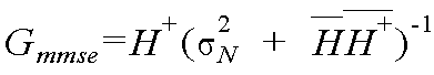
수학식 5에서 σ2 N은 노이즈의 분산이다. 상기 수학식 5를 통해 노이즈 분산을 정확히 산출해야 수신 성능의 열화를 방지할 수 있음을 알 수 있다. 상기 수학식 5를 수학식 2에 대입하면 수학식 6과 같이 쓸 수 있다. In

본 발명에 따른 OFDM 수신장치의 등화기는 상기 노이즈의 분산을 측정하기 위해 TPS 데이터를 사용한다. The equalizer of the OFDM receiver according to the present invention uses the TPS data to measure the variance of the noise.
상기 TPS 데이터는 프레임 그룹의 번호(frame group number), FEC 코드 레잇(forward error correction code rate), 타임-디인터리버 모드(time-deinterleaver mode) 등의 정보를 포함한다. The TPS data includes information such as a frame group number, a forward error correction code rate, a time-deinterleaver mode, and the like.
상기 TPS 데이터는 직교위상편이변조(quadrature phase shift keying ; QPSK)되어 있는데, 수신장치는 상기 TPS 데이터 신호를 쉽게 검출할 수 있고, 상기 TPS 데이터의 값은 변하지 않은 경우가 많기 때문에 주파수 영역에서 파일럿 신호처럼 사용할 수 있다. The TPS data is quadrature phase shift keying (QPSK), and since the receiver can easily detect the TPS data signal and the value of the TPS data is often unchanged, the pilot signal is in the frequency domain. Can be used like
뿐만 아니라 상기 TPS 데이터 신호가 다른 신호보다 파워의 크기가 크게 전송될 경우 수신장치는 상기 TPS 데이터 신호를 더 확실히 검출하여 사용할 수 있다. In addition, when the TPS data signal is transmitted with a greater magnitude of power than other signals, the receiving device can more reliably detect and use the TPS data signal.
도 5는 본 발명에 따른 OFDM 수신장치의 등화기에서 TPS 분산을 추출하는 TPS 분산산출부(200)의 일 실시예를 나타낸다.5 shows an embodiment of a TPS
상기 TPS 분산산출부(200)는 TPS 복호화부(210), 기준TPS생성부(220)와 TPS의 분산을 산출하는 제 2연산기(230)와 제 3연산기(240)를 포함할 수 있다. 상기 TPS 복호화부(210)는 제 1 등화부(190)에서 출력하는 데이터의 채널보상된 심벌 중 TPS 데이터에 해당하는 심벌을 복호화한다. The
상기 기준TPS생성부(220)는 TPS 데이터가 거의 변화하지 않는다는 것을 이용하여 OFDM 송신단에서 송신한 기준 TPS 데이터를 생성한다. The reference
상기 제 2 연산기(230)는 상기 TPS 복호화부(210)의 복호화된 심벌과 상기 기준TPS생성부(220)의 기준 TPS 데이터의 차를 계산한다.The
상기 제 3 연산기(240)는 상기 제 2 연산기(230)가 산출하는 차를 제곱하여 노이즈의 분산을 계산할 수 있다. The
TPS 데이터는 일반적으로 하나의 프레임에 36개가 있을 수 있는데, 상기 36 개에 대한 분산의 평균치를 이용하여 프레임 단위로 노이즈의 파워에 대한 분산을 구할 수 있다. In general, there may be 36 TPS data in one frame, and the variance of the power of noise may be obtained in units of frames by using the average of the variances of the 36 frames.
상기 노이즈의 파워의 분산을 산출하는 과정은 수학식 7에 나타냈다. 수학식 7에서 아래첨자 T는 TPS 데이터 구간임을 나타내는 것으로서 일 예로 NT는 TPS 데이터의 개수를 나타낸다.The process of calculating the variance of the power of the noise is shown in equation (7). In Equation 7, subscript T indicates a TPS data interval, and as an example, N T indicates the number of TPS data.

수학식 7에서 YT는 수신한 TPS 데이터, ![]()
![]()
도 6은 컨스털레이션(constellation)상에서 수신한 TPS 심벌과 송신단에서 송신하는 기준 TPS 데이터로 노이즈 분산의 크기를 구할 수 있음을 나타내는 도면이다. 수평축은 동위위상신호(I 신호), 수직축은 직교위상신호(Q 신호)에 해당한다.FIG. 6 is a diagram illustrating that the amount of noise variance can be obtained from the TPS symbol received on the constellation and the reference TPS data transmitted from the transmitter. The horizontal axis corresponds to an in-phase signal (I signal) and the vertical axis corresponds to a quadrature phase signal (Q signal).
상기 제 1등화부(190)가 출력하는 TPS 데이터와 기준TPS생성부(220)의 기준 TPS 데이터의 오차로 노이즈의 신호차이를 출력할 수 있다. The signal difference of the noise may be output due to an error between the TPS data output by the
상기에서 설명한 본 발명에 따른 직교주파수다중분할방식으로 변조된 방송신호를 수신하는 장치의 등화기의 효과를 설명하면 다음과 같다.Referring to the effect of the equalizer of the apparatus for receiving the broadcast signal modulated by the orthogonal frequency multiplexing method according to the present invention described above are as follows.
본 발명에 따른 등화기에 따르면 널 캐리어를 사용하지 않고 채널을 보상할 수 있으며, 채널의 보상 성능을 향상시킬 수 있다. According to the equalizer according to the present invention, the channel can be compensated without using a null carrier, and the compensation performance of the channel can be improved.
Claims (6)
Priority Applications (1)
| Application Number | Priority Date | Filing Date | Title |
|---|---|---|---|
| KR1020050079089A KR100651913B1 (en) | 2005-08-26 | 2005-08-26 | Equalizer in receiver of orthogonal frequency division multiplexed signals |
Applications Claiming Priority (1)
| Application Number | Priority Date | Filing Date | Title |
|---|---|---|---|
| KR1020050079089A KR100651913B1 (en) | 2005-08-26 | 2005-08-26 | Equalizer in receiver of orthogonal frequency division multiplexed signals |
Publications (1)
| Publication Number | Publication Date |
|---|---|
| KR100651913B1 true KR100651913B1 (en) | 2006-12-01 |
Family
ID=37731548
Family Applications (1)
| Application Number | Title | Priority Date | Filing Date |
|---|---|---|---|
| KR1020050079089A KR100651913B1 (en) | 2005-08-26 | 2005-08-26 | Equalizer in receiver of orthogonal frequency division multiplexed signals |
Country Status (1)
| Country | Link |
|---|---|
| KR (1) | KR100651913B1 (en) |
Citations (3)
| Publication number | Priority date | Publication date | Assignee | Title |
|---|---|---|---|---|
| KR20010103015A (en) * | 1999-02-18 | 2001-11-17 | 추후제출 | Method and device for equalizing and decoding a data signal |
| KR20020068341A (en) * | 1999-11-10 | 2002-08-27 | 아이비큐티 디지털 코포레이션 | Method and apparatus for transmission and reception of fm in-band on-channel digital audio broadcasting |
| KR20050021510A (en) * | 2002-07-18 | 2005-03-07 | 인터디지탈 테크날러지 코포레이션 | Scaling using gain factors for use in data detection for wireless code division multiple access communication systems |
-
2005
- 2005-08-26 KR KR1020050079089A patent/KR100651913B1/en not_active IP Right Cessation
Patent Citations (3)
| Publication number | Priority date | Publication date | Assignee | Title |
|---|---|---|---|---|
| KR20010103015A (en) * | 1999-02-18 | 2001-11-17 | 추후제출 | Method and device for equalizing and decoding a data signal |
| KR20020068341A (en) * | 1999-11-10 | 2002-08-27 | 아이비큐티 디지털 코포레이션 | Method and apparatus for transmission and reception of fm in-band on-channel digital audio broadcasting |
| KR20050021510A (en) * | 2002-07-18 | 2005-03-07 | 인터디지탈 테크날러지 코포레이션 | Scaling using gain factors for use in data detection for wireless code division multiple access communication systems |
Similar Documents
| Publication | Publication Date | Title |
|---|---|---|
| CN105103485B (en) | Transmitter and method for transmitting payload data in OFDM system, and receiver and method for receiving payload data | |
| KR101026469B1 (en) | Carrier frequency synchronization apparatus and method in ofdm system | |
| US6850481B2 (en) | Channels estimation for multiple input—multiple output, orthogonal frequency division multiplexing (OFDM) system | |
| JP5546358B2 (en) | Data processing apparatus and data processing method | |
| US7856068B1 (en) | Nested preamble for multi input multi output orthogonal frequency division multiplexing | |
| US20070086328A1 (en) | Method and circuit for frequency offset estimation in frequency domain in the orthogonal frequency division multiplexing baseband receiver for IEEE 802.11A/G wireless LAN standard | |
| JP2005057644A5 (en) | ||
| KR20110007063A (en) | Receiver and method | |
| KR100246452B1 (en) | Apparatus and method for frequency synchronization using orthogonal frequency division multiplexing | |
| WO2014155065A1 (en) | Transmitter and method of transmitting payload data, receiver and method of receiving payload data in an ofdm system | |
| KR100406975B1 (en) | Apparatus for recovering symbol timing of OFDM Receiver and Method using the same | |
| KR20020056986A (en) | Modulator and demodulator using dispersed pilot subchannel and ofdm frame structure in orthogonal frequency division multiplexing system | |
| KR100793789B1 (en) | An apparatus for estimating channel and a method thereof | |
| KR20110108364A (en) | Method and apparatus for estimating phase noise in an ofdm transmission system | |
| IL131951A (en) | Method for rapid carrier frequency estimation in a communication system | |
| KR100739552B1 (en) | apparatus for receiving a signal of orthogonal frequency division multiplexing | |
| KR100651913B1 (en) | Equalizer in receiver of orthogonal frequency division multiplexed signals | |
| KR100236039B1 (en) | A coarse time acquisition for ofdm | |
| KR100662392B1 (en) | Apparatus for receiving broadcast | |
| KR20070119915A (en) | Equalizing method and apparatus | |
| KR100747543B1 (en) | Apparatus for demodulating broadcasting signal | |
| KR100789833B1 (en) | Equalizer | |
| KR100662418B1 (en) | Apparatus for receiving orthogonal frequency division multiplexed signals | |
| KR100735695B1 (en) | apparatus for receiving a signal of orthogonal frequency division multiplexing | |
| KR20070075827A (en) | Apparatus for demodulating broadcast signal |
Legal Events
| Date | Code | Title | Description |
|---|---|---|---|
| A201 | Request for examination | ||
| E701 | Decision to grant or registration of patent right | ||
| GRNT | Written decision to grant | ||
| FPAY | Annual fee payment |
Payment date: 20121026 Year of fee payment: 7 |
|
| FPAY | Annual fee payment |
Payment date: 20131024 Year of fee payment: 8 |
|
| FPAY | Annual fee payment |
Payment date: 20141024 Year of fee payment: 9 |
|
| FPAY | Annual fee payment |
Payment date: 20151023 Year of fee payment: 10 |
|
| LAPS | Lapse due to unpaid annual fee |