KR100550570B1 - High efficiency dehumidification air conditioner and control method - Google Patents
High efficiency dehumidification air conditioner and control method Download PDFInfo
- Publication number
- KR100550570B1 KR100550570B1 KR1020040027783A KR20040027783A KR100550570B1 KR 100550570 B1 KR100550570 B1 KR 100550570B1 KR 1020040027783 A KR1020040027783 A KR 1020040027783A KR 20040027783 A KR20040027783 A KR 20040027783A KR 100550570 B1 KR100550570 B1 KR 100550570B1
- Authority
- KR
- South Korea
- Prior art keywords
- heat exchanger
- indoor
- dehumidification
- air
- regeneration
- Prior art date
- Legal status (The legal status is an assumption and is not a legal conclusion. Google has not performed a legal analysis and makes no representation as to the accuracy of the status listed.)
- Expired - Fee Related
Links
Images


Classifications
-
- G—PHYSICS
- G04—HOROLOGY
- G04B—MECHANICALLY-DRIVEN CLOCKS OR WATCHES; MECHANICAL PARTS OF CLOCKS OR WATCHES IN GENERAL; TIME PIECES USING THE POSITION OF THE SUN, MOON OR STARS
- G04B19/00—Indicating the time by visual means
- G04B19/30—Illumination of dials or hands
- G04B19/32—Illumination of dials or hands by luminescent substances
-
- G—PHYSICS
- G04—HOROLOGY
- G04B—MECHANICALLY-DRIVEN CLOCKS OR WATCHES; MECHANICAL PARTS OF CLOCKS OR WATCHES IN GENERAL; TIME PIECES USING THE POSITION OF THE SUN, MOON OR STARS
- G04B19/00—Indicating the time by visual means
- G04B19/06—Dials
- G04B19/10—Ornamental shape of the graduations or the surface of the dial; Attachment of the graduations to the dial
- G04B19/103—Ornamental shape of the graduations or the surface of the dial; Attachment of the graduations to the dial attached or inlaid numbers
Landscapes
- Physics & Mathematics (AREA)
- General Physics & Mathematics (AREA)
- Drying Of Gases (AREA)
- Central Air Conditioning (AREA)
Abstract
본 발명에 따른 고효율 제습 공기조화기는 열교환기로 공급되는 제습재가 열교환기로 송풍되는 공기를 제습하고, 수분을 흡수한 제습재가 재생되어 재사용되어, 압축기의 오프시에도 제습 운전을 실시할 수 있으므로, 소비 전력을 저감할 수 있고, 제습 운전시 찬 공기가 토출되지 않아 불쾌감을 해소할 수 있는 이점이 있다.In the high efficiency dehumidification air conditioner according to the present invention, the dehumidifying material supplied to the heat exchanger dehumidifies the air blown to the heat exchanger, the dehumidifying material absorbing the moisture is regenerated and reused, so that the dehumidifying operation can be performed even when the compressor is turned off. It is possible to reduce the cold air is not discharged during the dehumidification operation there is an advantage that can eliminate the discomfort.
공기조화기, 실내기, 실외기, 제습제, 제습 펌프, 재생 열교환기, 재생 펌프, 열원 Air Conditioner, Indoor Unit, Outdoor Unit, Dehumidifier, Dehumidification Pump, Regenerative Heat Exchanger, Regenerative Pump, Heat Source
Description
도 1은 본 발명에 따른 고효율 제습 공기조화기 제 1 실시예의 사시도,1 is a perspective view of a first embodiment of a high efficiency dehumidification air conditioner according to the present invention;
도 2는 본 발명에 따른 고효율 제습 공기조화기 제 1 실시예의 내부 구성이 도시된 개략도,Figure 2 is a schematic diagram showing the internal configuration of a first embodiment of a high efficiency dehumidification air conditioner according to the present invention,
도 3은 본 발명에 따른 고효율 제습 공기조화기 제 1 실시예의 제어 블록도,3 is a control block diagram of a first embodiment of a high efficiency dehumidification air conditioner according to the present invention;
도 4는 본 발명에 따른 고효율 제습 공기조화기의 제어 방법 제 1 실시예의 순서도,4 is a flow chart of a first embodiment of a method for controlling a high efficiency dehumidification air conditioner according to the present invention;
도 5는 본 발명에 따른 고효율 제습 공기조화기의 제어 방법 제 2 실시예의 순서도,5 is a flowchart of a second embodiment of a method for controlling a high efficiency dehumidification air conditioner according to the present invention;
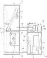
도 6은 본 발명에 따른 고효율 제습 공기조화기 제 2 실시예의 내부 구성이 도시된 개략도,6 is a schematic diagram showing the internal configuration of a second embodiment of a high efficiency dehumidification air conditioner according to the present invention;
도 7은 본 발명에 따른 고효율 제습 공기조화기 제 3 실시예의 내부 구성이 도시된 개략도,7 is a schematic diagram showing the internal configuration of a third embodiment of a high efficiency dehumidification air conditioner according to the present invention;
도 8은 본 발명에 따른 고효율 제습 공기조화기 제 4 실시예의 내부 구성이 도시된 개략도,8 is a schematic diagram showing the internal configuration of a fourth embodiment of a high efficiency dehumidification air conditioner according to the present invention;
도 9는 본 발명에 따른 고효율 제습 공기조화기 제 4 실시예의 제어 블록도,9 is a control block diagram of a fourth embodiment of a high efficiency dehumidification air conditioner according to the present invention;
도 10은 본 발명에 따른 고효율 제습 공기조화기 제 5 실시예의 내부 구성이 도시된 개략도,10 is a schematic diagram showing the internal configuration of a fifth embodiment of a high efficiency dehumidification air conditioner according to the present invention;
도 11은 본 발명에 따른 고효율 제습 공기조화기 제 6 실시예의 내부 구성이 도시된 개략도,11 is a schematic diagram showing an internal configuration of a sixth embodiment of a high efficiency dehumidification air conditioner according to the present invention;
도 12는 본 발명에 따른 고효율 제습 공기조화기 제 6 실시예의 제어 블록도,12 is a control block diagram of a sixth embodiment of a high efficiency dehumidification air conditioner according to the present invention;
도 13은 본 발명에 따른 고효율 제습 공기조화기 제 7 실시예의 내부 구성이 도시된 개략도이다.Figure 13 is a schematic diagram showing the internal configuration of a seventh embodiment of a high efficiency dehumidification air conditioner according to the present invention.
<도면의 주요 부분에 관한 부호의 설명><Explanation of symbols on main parts of the drawings>
2: 실내기 4: 실내 열교환기2: indoor unit 4: indoor heat exchanger
5, 5′: 드레인 팬 6: 실내 팬5, 5 ′: Drain pan 6: Indoor fan
8, 8′: 제습 펌프 10: 실외기8, 8 ′: Dehumidification pump 10: Outdoor unit
10a: 연통홀 10a′: 토출홀10a:
12: 압축기 14: 실외 열교환기12: compressor 14: outdoor heat exchanger
16: 팽창기구 18: 실외 팬16: inflator 18: outdoor fan
20: 재생수단 22: 재생 열교환기20: regeneration means 22: regeneration heat exchanger
24: 열원 24′: 집열판24: heat source 24 ': heat collecting plate
26: 재생 펌프 28, 28′, 28″: 재생 팬26:
30, 30′, 30″: 덕트 30a, 30a′,30a″: 흡입구30, 30 ', 30 ":
30b, 30b′,30b″: 토출구 32: 제 1 호스30b, 30b ', 30b ″: discharge port 32: first hose
34: 제 2 호스 36: 제 3 호스34: second hose 36: third hose
42: 운전 조작부 44: 제어부42: operation control unit 44: control unit
D: 제습재 D′: 수분이 흡수된 제습재D: Dehumidifier D ′: Dehumidifier absorbed moisture
본 발명은 고효율 제습 공기조화기 및 그 제어 방법에 관한 것으로서, 특히 제습재를 증발기에 공급하여 실내 공기를 제습토록 하는 고효율 제습 공기조화기 및 그 제어 방법에 관한 것이다.The present invention relates to a high efficiency dehumidification air conditioner and a control method thereof, and more particularly, to a high efficiency dehumidification air conditioner for supplying a dehumidifier to an evaporator to dehumidify indoor air and a control method thereof.
일반적으로 공기조화기는 사용자에게 보다 쾌적한 실내 환경을 조성하기 위해 압축기, 응축기, 팽창기구, 증발기로 이루어지는 냉매의 냉동사이클을 이용하여 실내를 냉/난방 시키는 장치로서, 난방 기능의 여부에 따라 냉방과 난방을 선택적으로 수행할 수 있는 냉/난방기와, 냉방만을 수행하는 냉방기 등으로 구분된다.In general, an air conditioner is a device that cools and heats a room by using a refrigeration cycle of a refrigerant consisting of a compressor, a condenser, an expansion device, and an evaporator to create a more comfortable indoor environment for a user. It is divided into a cooling / heating that can be selectively performed, and a cooling unit that performs only cooling.
상기 냉/난방기는 상기 냉동 사이클로 냉방을 수행하고, 별도의 난방용 히터 혹은 난방 덕트로 난방을 수행하는 것과, 상기 냉동 사이클의 냉매 순환 방향을 전환하여 냉방과 난방을 선택적으로 행하는 것(이하, 히트 펌프라 칭함) 등이 있다.The cooling / heater performs cooling by the refrigerating cycle, heating by a separate heating heater or heating duct, and selectively cooling and heating by changing a refrigerant circulation direction of the refrigerating cycle (hereinafter, a heat pump). And the like).
또한, 상기 공기조화기는 실내기와 실외기의 분할 여부에 따라 일체형과 분리형으로 구분된다.In addition, the air conditioner is classified into an integrated type and a separate type according to whether the indoor unit and the outdoor unit are divided.
상기한 일체형과 분리형은 기능적으로는 같지만, 상기 일체형은 압축기, 응 축기, 팽창기구, 증발기가 하나의 장치 내에 내장되고, 상기 장치를 실외에 설치하고 상기 장치에 흡입덕트/토출덕트를 연결하거나, 상기 장치를 건물의 벽 또는 창에 설치하는 것이다.The integrated type and the separated type are functionally the same, but the integrated type includes a compressor, a condenser, an expansion device, and an evaporator in one device, and the device is installed outdoors and a suction duct / discharge duct is connected to the device. The device is installed on a wall or window of a building.
반면에, 분리형은 실내기와 실외기에 상기 압축기와 응축기와 팽창기구와 증발기가 나뉘어 내장되고, 실내기와 실외기가 냉매배관으로 연결되어, 실내기가 냉방 혹은 난방을 기능을 수행한다.On the other hand, in the separate type, the compressor, the condenser, the expansion device, and the evaporator are divided into the indoor unit and the outdoor unit, and the indoor unit and the outdoor unit are connected to the refrigerant pipe, and the indoor unit performs cooling or heating functions.
상기와 같은 공기조화기는 사용자의 조작 등에 의해 냉방 운전과 난방 운전과 제습 운전 등의 운전이 실시된다.The air conditioner as described above is operated by the user's operation, such as cooling operation, heating operation and dehumidification operation.
상기 제습 운전은 실내 습도가 높을 때 실시되는 것으로서, 실내에서 흡입된 공기가 증발기를 통과하는 차가운 냉매에 의해 제습될 수 있도록 압축기가 온됨과 아울러 실내팬의 풍량이 약풍으로 제어된다.The dehumidification operation is performed when the indoor humidity is high, and the compressor is turned on so that the air sucked in the room can be dehumidified by the cold refrigerant passing through the evaporator, and the air volume of the indoor fan is controlled by the weak wind.
압축기의 온시 압축기에서 압축된 고온, 고압의 기체 냉매는 응축기로 보내져서 주변 공기로 열을 방출하여 응축되고, 응축된 냉매는 팽창기구를 지나면서 저온, 저압으로 팽창되며, 팽창된 냉매는 증발기로 보내져서 주변 공기로부터 열을 흡수하여 증발되고, 증발된 저온 저압의 기체 냉매는 압축기로 순환된다.When the compressor is turned on, the high-temperature and high-pressure gas refrigerant compressed by the compressor is sent to the condenser to release heat to the surrounding air to condense. It is sent to absorb heat from the surrounding air and evaporated, and the evaporated low temperature low pressure gas refrigerant is circulated to the compressor.
그리고, 실내팬의 약풍 제어시 실내 공기는 증발기를 통과하는 냉매에 열을 빼앗겨서 수분이 증발기 표면에 응축되고, 수분이 제거된 차가운 건조 공기만이 실내로 토출된다.In the control of the indoor air, the indoor air loses heat to the refrigerant passing through the evaporator, so that the moisture is condensed on the surface of the evaporator, and only the cool dry air from which the moisture is removed is discharged into the room.
그러나, 종래 기술에 따른 공기조화기는 제습 운전시 압축기가 냉방 운전과 같이 운전되므로, 압축기 구동에 소비 전력이 요구되고, 찬 공기가 실내로 토출되 어 사용자에게 불쾌감을 줄 수 있는 이점이 있다.However, in the air conditioner according to the prior art, since the compressor is operated as the cooling operation during the dehumidification operation, power consumption is required for driving the compressor, and the cold air is discharged to the room, thereby providing an inconvenience to the user.
본 발명은 상기한 종래 기술의 문제점을 해결하기 위하여 안출된 것으로서, 제습 운전시 압축기가 오프이거나 저용량으로 운전되어 소비 전력을 저감할 수 있고, 제습 운전시 발생될 수 있는 불쾌감을 해소할 수 있는 고효율 제습 공기조화기를 제공하는데 그 목적이 있다.The present invention has been made to solve the above-described problems of the prior art, the compressor is turned off or dehumidified during the dehumidification operation to reduce power consumption, high efficiency that can eliminate the discomfort that may occur during dehumidification operation Its purpose is to provide a dehumidifying air conditioner.
본 발명의 다른 목적은 제습재를 이용한 제습과 제습재의 재생이 함께 이루어져 장기간 제습 운전을 실시할 수 있는 고효율 제습 공기조화기의 제어 방법을 제공하는 것이다.Another object of the present invention is to provide a control method of a high-efficiency dehumidification air conditioner that can perform a dehumidification operation for a long time by the dehumidification using the dehumidifying material and the regeneration of the dehumidifying material.
본 발명의 또 다른 목적은 제습 운전시 실내 공기의 온도 변화 없이 제습만을 실시할 수 있는 고효율 제습 공기조화기의 제어 방법을 제공하는 것이다.
Still another object of the present invention is to provide a control method of a high efficiency dehumidification air conditioner capable of performing only dehumidification without changing the temperature of indoor air during dehumidification operation.
상기한 과제를 해결하기 위한 본 발명에 따른 고효율 제습 공기조화기는 실내 공기와 열교환되는 실내 열교환기와, 상기 실내 열교환기로 실내 공기를 송풍시키는 실내팬을 포함하는 실내기와; 냉매를 압축하는 압축기와, 실외 공기와 열교환되는 실외 열교환기를 포함하는 실외기와; 상기 실내 열교환기로 송풍된 공기가 제습될 수 있도록 상기 실내 열교환기의 표면으로 제습재를 펌핑하는 제습 펌프와; 상기 실내 열교환기에서 낙하된 제습재를 받을 수 있도록 상기 실내 열교환기의 하측에 설치된 드레인 팬과; 상기 드레인 팬으로 낙하된 수분을 흡수한 제습재를 펌핑시키는 재생 펌프를 포함하는 고효율 제습 공기조화기에 있어서, 상기 재생 펌프에 의해 펌핑된 수분을 흡수한 제습재가 통과하는 재생 열교환기와; 상기 재생 열교환기를 통과하는 수분을 흡수한 제습재가 열에 의해 재생될 수 있도록 전압이 인가되면 발열되어 상기 재생 열교환기를 가열하는 발열 히터를 포함하여 구성된 것을 특징으로 한다.
또한, 상기 고효율 제습 공기조화기는 공기가 상기 발열 히터에 의해 가열되어 상기 재생 열교환기를 가열할 수 있도록 공기를 송풍시키는 재생 팬을 더 포함하여 구성된 것을 특징으로 한다.
또한, 상기 고효율 제습 공기조화기는 공기가 상기 열원을 지나 상기 재생 열교환기로 안내되도록 설치된 덕트를 더 포함하여 구성된 것을 특징으로 한다.The high efficiency dehumidification air conditioner according to the present invention for solving the above problems is an indoor heat exchanger comprising an indoor heat exchanger that heat-exchanges with indoor air, and an indoor fan that blows indoor air into the indoor heat exchanger; An outdoor unit including a compressor for compressing a refrigerant and an outdoor heat exchanger configured to exchange heat with outdoor air; A dehumidification pump for pumping a dehumidifier to the surface of the indoor heat exchanger so that the air blown by the indoor heat exchanger is dehumidified; A drain pan installed below the indoor heat exchanger to receive the dehumidifying material dropped from the indoor heat exchanger; A high efficiency dehumidification air conditioner including a regeneration pump for pumping a dehumidifier absorbing moisture dropped into the drain pan, comprising: a regeneration heat exchanger through which a dehumidifier absorbing moisture pumped by the regeneration pump passes; It characterized in that it comprises a heat generating heater that generates heat when the voltage is applied so that the dehumidifying material absorbing the moisture passing through the regeneration heat exchanger is heated by heat to heat the regeneration heat exchanger.
In addition, the high efficiency dehumidification air conditioner is characterized in that it further comprises a regeneration fan for blowing the air so that the air is heated by the heat generating heater to heat the regeneration heat exchanger.
In addition, the high efficiency dehumidification air conditioner is characterized in that it further comprises a duct installed so that air is guided to the regeneration heat exchanger through the heat source.
삭제delete
삭제delete
삭제delete
삭제delete
삭제delete
삭제delete
삭제delete
삭제delete
삭제delete
본 발명에 따른 고효율 제습 공기조화기는 실내 공기와 열교환되는 실내 열교환기와, 상기 실내 열교환기로 실내 공기를 송풍시키는 실내팬을 포함하는 실내기와; 냉매를 압축하는 압축기와, 실외 공기와 열교환되는 실외 열교환기를 포함하는 실외기와; 상기 실내 열교환기로 송풍된 공기가 제습될 수 있도록 상기 실내 열교환기의 표면으로 제습재를 펌핑하는 제습 펌프와; 상기 실내 열교환기에서 낙하된 제습재를 받을 수 있도록 상기 실내 열교환기의 하측에 설치된 드레인 팬과; 상기 드레인 팬으로 낙하된 수분을 흡수한 제습재를 펌핑시키는 재생 펌프를 포함하는 고효율 제습 공기조화기에 있어서, 상기 재생 펌프에 의해 펌핑된 수분을 흡수한 제습재가 통과하는 재생 열교환기와; 상기 재생 열교환기를 통과하는 수분을 흡수한 제습재가 열에 의해 재생될 수 있도록 태양 에너지가 축적되어 상기 재생 열교환기를 가열하는 집열판을 포함하여 구성된 것을 특징으로 한다. The high efficiency dehumidification air conditioner according to the present invention comprises: an indoor heat exchanger which heat-exchanges with indoor air, and an indoor unit including an indoor fan which blows indoor air to the indoor heat exchanger; An outdoor unit including a compressor for compressing a refrigerant and an outdoor heat exchanger configured to exchange heat with outdoor air; A dehumidification pump for pumping a dehumidifier to the surface of the indoor heat exchanger so that the air blown by the indoor heat exchanger can be dehumidified; A drain pan installed below the indoor heat exchanger to receive the dehumidifying material dropped from the indoor heat exchanger; A high efficiency dehumidification air conditioner including a regeneration pump for pumping a dehumidifier absorbing moisture dropped into the drain pan, comprising: a regeneration heat exchanger through which a dehumidifier absorbing moisture pumped by the regeneration pump passes; And a heat collecting plate configured to heat the regenerative heat exchanger by accumulating solar energy so that the dehumidifying material absorbing moisture passing through the regenerative heat exchanger may be regenerated by heat.
본 발명에 따른 고효율 제습 공기조화기는 실내 공기와 열교환되는 실내 열교환기와, 상기 실내 열교환기로 실내 공기를 송풍시키는 실내팬을 포함하는 실내기와; 냉매를 압축하는 압축기와, 실외 공기와 열교환되는 실외 열교환기를 포함하는 실외기와; 상기 실내 열교환기로 송풍된 공기가 제습될 수 있도록 상기 실내 열교환기의 표면으로 제습재를 펌핑하는 제습 펌프와; 상기 실내 열교환기에서 낙하된 제습재를 받을 수 있도록 상기 실내 열교환기의 하측에 설치된 드레인 팬과; 상기 드레인 팬으로 낙하된 수분을 흡수한 제습재를 펌핑시키는 재생 펌프를 포함하는 고효율 제습 공기조화기에 있어서, 상기 재생 펌프에 의해 펌핑된 수분을 흡수한 제습재가 통과하고 상기 압축기에서 방출된 열에 의해 가열되도록 설치되어 수분을 흡수한 제습재를 재생시키는 재생 열교환기를 포함하여 구성된 것을 특징으로 한다.
또한, 상기 제습 펌프는 상기 제습재를 상기 실내 열교환기의 상부와 하부 중에서 하부로 공급하도록 배치되고, 기 드레인 팬은 상기 실내 열교환기의 하단 하측부터 상기 제습재가 공급되는 부위의 하측에 이르도록 배치된 것을 특징으로 한다. The high efficiency dehumidification air conditioner according to the present invention comprises: an indoor heat exchanger which heat-exchanges with indoor air, and an indoor unit including an indoor fan which blows indoor air to the indoor heat exchanger; An outdoor unit including a compressor for compressing a refrigerant and an outdoor heat exchanger configured to exchange heat with outdoor air; A dehumidification pump for pumping a dehumidifying material onto a surface of the indoor heat exchanger so that the air blown by the indoor heat exchanger can be dehumidified; A drain pan installed below the indoor heat exchanger to receive the dehumidifying material dropped from the indoor heat exchanger; A high efficiency dehumidification air conditioner including a regeneration pump for pumping a dehumidifying material absorbing moisture dropped into the drain pan, wherein the dehumidifying material absorbed by the regeneration pump passes and is heated by heat released from the compressor. It is installed so as to comprise a regeneration heat exchanger for regenerating the dehumidifying material absorbing moisture.
In addition, the dehumidification pump is arranged to supply the dehumidifying material to the lower portion of the upper and lower parts of the indoor heat exchanger, the air drain fan is arranged so as to extend from the lower side of the lower end of the indoor heat exchanger to the lower side of the portion to which the dehumidifying material is supplied. It is characterized by.
본 발명에 따른 고효율 제습 공기조화기의 제어 방법은 실내 공기와 열교환되는 실내 열교환기와, 상기 실내 열교환기로 실내 공기를 송풍시키는 실내팬을 포함하는 실내기와; 냉매를 압축하는 압축기와, 실외 공기와 열교환되는 실외 열교환기를 포함하는 실외기와; 상기 실내 열교환기로 송풍된 공기가 제습될 수 있도록 상기 실내 열교환기의 표면으로 제습재를 펌핑하는 제습 펌프와; 상기 실내 열교환기에서 낙하된 제습재를 받을 수 있도록 상기 실내 열교환기의 하측에 설치된 드레인 팬과; 상기 드레인 팬으로 낙하된 수분을 흡수한 제습재를 펌핑시키는 재생 펌프와; 상기 재생 펌프에 의해 펌핑된 수분을 흡수한 제습재가 통과하는 재생 열교환기를 포함하는 고효율 제습 공기조화기의 제어 방법에 있어서, 제습 운전시 상기 실내팬과, 제습 펌프와, 재생 펌프를 온시키고, 상기 재생 열교환기를 가열하기 위한 열원을 상기 실내팬과 제습 펌프와 재생 펌프와 함께 온시키는 것을 특징으로 한다.The control method of the high efficiency dehumidification air conditioner according to the present invention comprises: an indoor heat exchanger which heat-exchanges with indoor air, and an indoor unit including an indoor fan which blows indoor air to the indoor heat exchanger; An outdoor unit including a compressor for compressing a refrigerant and an outdoor heat exchanger configured to exchange heat with outdoor air; A dehumidification pump for pumping a dehumidifier to the surface of the indoor heat exchanger so that the air blown by the indoor heat exchanger can be dehumidified; A drain pan installed below the indoor heat exchanger to receive the dehumidifying material dropped from the indoor heat exchanger; A regeneration pump for pumping a dehumidifying material absorbing moisture dropped into the drain pan; A control method of a high efficiency dehumidification air conditioner including a regeneration heat exchanger through which a dehumidifier absorbing moisture pumped by the regeneration pump passes, wherein the indoor fan, a dehumidification pump, and a regeneration pump are turned on during a dehumidification operation, The heat source for heating the regeneration heat exchanger is characterized in that it is turned on together with the indoor fan, the dehumidification pump and the regeneration pump.
또한, 상기 고효율 제습 공기조화기의 제어 방법은 제습 운전시 상기 압축기를 오프시키는 것을 특징으로 한다.In addition, the control method of the high efficiency dehumidification air conditioner is characterized in that the compressor is turned off during the dehumidification operation.
또한, 상기 고효율 제습 공기조화기의 제어 방법은 제습 운전시 상기 제습재에 의한 공기의 승온을 막을 수 있도록 상기 실내 열교환기의 표면에 응축수가 생성되지 않는 용량으로 상기 압축기를 구동시키는 것을 특징으로 한다.In addition, the control method of the high-efficiency dehumidification air conditioner is characterized in that the compressor is driven with a capacity that does not generate condensate water on the surface of the indoor heat exchanger to prevent the temperature rise of the air by the dehumidifier during the dehumidification operation. .
삭제delete
이하, 본 발명의 실시 예를 첨부된 도면을 참조하여 상세히 설명한다.Hereinafter, embodiments of the present invention will be described in detail with reference to the accompanying drawings.
도 1은 본 발명에 따른 고효율 제습 공기조화기 제 1 실시예의 사시도이고, 도 2는 본 발명에 따른 고효율 제습 공기조화기 제 1 실시예의 내부 구성이 도시된 개략도이다.Figure 1 is a perspective view of a first embodiment of a high efficiency dehumidification air conditioner according to the present invention, Figure 2 is a schematic diagram showing the internal configuration of a first embodiment of a high efficiency dehumidification air conditioner according to the present invention.
본 실시예에 따른 고효율 제습 공기조화기는 도 1 및 도 2에 도시된 바와 같이, 실내기(2)와, 상기 실내기(2)와 냉매배관(9a,9b)으로 연결된 실외기(10)를 포함하여 구성된다.As shown in FIGS. 1 and 2, the high efficiency dehumidification air conditioner according to the present embodiment includes an
상기 실내기(2)에는 냉매가 통과하는 실내 열교환기(4)와, 실내의 공기를 상기 실내기(2) 내부로 흡입하여 상기 실내 열교환기(4)로 송풍시킨 후 실내로 다시 토출시키는 실내팬(6)과, 상기 열교환기(4)로 송풍된 공기가 제습될 수 있도록 상기 열교환기(4)의 표면으로 제습재(D)를 공급하는 제습수단이 설치된다.The indoor unit (2) has an indoor heat exchanger (4) through which a refrigerant passes, and an indoor fan that sucks indoor air into the indoor unit (2), blows it into the indoor heat exchanger (4), and discharges it back to the room ( 6) and dehumidifying means for supplying a dehumidifying material D to the surface of the
상기 실내 열교환기(4)의 하측에는 냉방 운전시 상기 실내 열교환기(4)에서 낙하된 응축수를 받고 제습 운전시 상기 실내 열교환기(4)에서 낙하된 수분을 흡수한 제습재(D′)를 받을 수 있도록 드레인 팬(5)이 설치된다.Below the
상기 드레인 팬(5)은 상기 실내 열교환기(4)의 하단 하측에 배치된다. The
상기 제습재(D)는 리튬 클로라이드(LiCl) 등의 액체 제습재로서, 상기 실내 열교환기(4)로 공급된 후 곧바로 낙하되지 않고, 상기 실내 열교환기(4)의 표면을 따라 흐르도록 소정 이상의 점성을 갖는 것이 바람직하다.The dehumidifying material (D) is a liquid dehumidifying material such as lithium chloride (LiCl). The dehumidifying material (D) is a liquid dehumidifying material such as lithium chloride (LiCl). The dehumidifying material (D) does not fall immediately after being supplied to the indoor heat exchanger (4). It is preferable to have viscosity.
상기 제습수단은 상기 실내 열교환기(4)의 표면으로 제습재(D)를 펌핑하는 제습 펌프(8)로 구성된다.The dehumidifying means comprises a
상기 제습 펌프(8)는 상기 실내 열교환기(4)와 이격되게 장착되고, 상기 제습재(D)를 상기 실내 열교환기(4)의 표면으로 분사하는 노즐이 구비된다.The
상기 제습 펌프(8)는 제습재(D)와 공기의 접촉 면적이 크도록 제습재(D)를 상기 실내 열교환기(4)의 상부로 토출하게 배치됨이 바람직하다.The
상기 실외기(10)에는 저온 저압의 기체 냉매를 고온 고압으로 압축시키는 압축기(12)와, 상기 실내 열교환기(4)가 증발기로 이용되면 응축기로 작용하고, 상기 실내 열교화기(4)가 응축기로 이용되면 증발기로 작용하는 실외 열교환기(14)와, 응축기에서 응축된 냉매를 팽창시키는 팽창기구(16)와, 실외의 공기를 상기 실외기(10) 내부로 흡입하여 상기 실외 열교환기(14)로 송풍시킨 후 실외로 다시 토출시키는 실외팬(18)을 포함하여 구성된다.The
상기 고효율 제습 공기조화기는 상기 실내 열교환기(4)의 표면에서 수분을 흡수한 제습재(D′)를 재생시키는 재생수단(20)을 더 포함하여 구성된다.The high efficiency dehumidification air conditioner further comprises regeneration means 20 for regenerating the dehumidifying material D 'absorbing moisture from the surface of the
상기 재생수단(20)은 상기 실내기(2)와 실외기(10) 중 어느 하나의 내부에 설치되는 것도 가능하고, 상기 실내기(2) 및 실외기(10)와 독립적으로 이루어진 별도의 재생유닛으로 이루어지는 것도 가능하며, 이하, 설명의 편의를 위해 상기 실외기(20)의 상면에 별도로 설치된 재생 유닛으로 이루어지는 것으로 한정하여 설명한다.The regeneration means 20 may be installed inside any one of the
상기 재생수단(20)은 수분을 흡수한 제습재(D′)가 통과하는 재생 열교환기(22)와, 상기 재생 열교환기(22)를 가열하는 열원(24)을 포함하여 구성된다.The regeneration means 20 includes a
상기 열원(24)은 전압이 인가되면 발열되는 발열 히터이다.The
상기 재생수단(20)은 수분을 흡습한 제습재(D′)를 상기 재생 열교환기(22)로 펌핑시키는 재생 펌프(26)를 더 포함하여 구성된다.The regeneration means 20 further includes a
상기 재생수단(20)은 공기가 상기 열원(24)에 의해 가열되어 상기 재생 열교환기(22)를 가열할 수 있도록 공기를 송풍시키는 재생 팬(28)을 더 포함하여 구성된다.The regeneration means 20 further comprises a
상기 재생수단(20)은 상기 재생 팬(28)에 의해 흡입된 공기가 상기 열원(24)을 지나 상기 재생 열교환기(22)로 안내되도록 설치된 덕트(30)를 더 포함하여 구성된다.The regeneration means 20 further includes a
상기 덕트(30)는 상기 실외기(20)에 장착되고, 상기 재생 열교환기(22)와 열원(24)과 재생 펌프(26)와 재생 팬(28)이 내장되며, 공기가 흡입되는 흡입구(30a)와 공기가 토출되는 토출구(30b)가 형성된다.The
참조 부호 32는 상기 드레인 팬(5)에 낙하된 수분이 흡수된 재생재(D′)가 상기 재생 펌프(26)로 안내되도록 상기 드레인 팬(5)에 일단이 연결되고 상기 재생 펌프(26)에 타단이 연결된 제 1 호스이다.
참조 부호 34는 상기 재생 펌프(26)에 의해 펌핑된 수분이 흡수된 제습재(D′)가 상기 재생 열교환기(22)로 유입되도록 상기 재생 펌프(26)에 일단이 연결되고 상기 재생 열교환기(22)에 타단이 연결된 제 2 호스이다.
참조 부호 36은 상기 재생 열교환기(22)에서 재생된 제습재(D)가 상기 제습 펌프(6)로 안내되도록 상기 재생 열교환기(22)에 일단이 연결되고 상기 제습 펌프(6)에 타단이 연결된 제 3 호스이다.
도 3은 본 발명에 따른 고효율 제습 공기조화기 제 1 실시예의 제어 블록도 이다.3 is a control block diagram of a first embodiment of a high efficiency dehumidification air conditioner according to the present invention.
도 3에 도시된 바와 같이, 본 실시예에 따른 고효율 제습 공기조화기는 냉방 운전/제습 운전 등을 조작하는 운전 조작부(42)와, 상기 운전 조작부(42)의 조작에 따라 실내팬(6)과, 제습 펌프(8)와, 압축기(12)와, 실외팬(18)과, 열원(24)과, 재생 펌프(26)와, 재생 팬(28)을 온/오프시키는 제어부(44)를 더 포함하여 구성된다.As shown in FIG. 3, the high efficiency dehumidification air conditioner according to the present embodiment includes a driving
상기와 같이 구성된 본 발명의 동작을 살펴보면 다음과 같다.Looking at the operation of the present invention configured as described above are as follows.
먼저, 냉방 운전시 상기 제어부(44)는 상기 압축기(12)를 온시킴과 아울러 상기 실내 팬(6) 및 실외팬(18)을 온시킨다.First, during the cooling operation, the
상기 압축기(12)의 온시 상기 압축기(12)는 저온 저압의 증기 냉매를 압축하고, 압축된 저온 저압의 증기 냉매는 상기 실외 열교환기(14)를 통과하면서 주변으로 열을 방출하여 고압 상온의 액 냉매로 응축되며, 응축된 고압 상온의 액 냉매는 상기 팽창기구(16)를 통과하면서 저온 저압의 2상 냉매로 팽창되며, 팽창된 저온 저압의 2상 냉매는 상기 실내 열교환기(4)를 통과하면서 주변의 열을 빼앗아 저온 저압의 증기 냉매로 증발되고, 저온 저압의 기체 냉매는 상기 압축기(2)로 순환되어 상기의 과정을 반복하게 된다.When the
상기 실내 팬(6)의 온시 실내의 공기는 상기 실내기(2) 내로 흡입되고, 상기 실내 열교환기(4)로 열을 방출하여 냉각된 후 실내로 다시 토출되어 실내를 냉방시키고,When the
상기 실외 팬(18)의 온시 실외의 공기는 상기 실외기(10)로 흡입되고, 상기 실외 열교환기(14)의 열을 빼앗은 후 실외로 다시 토출된다.When the
도 4는 본 발명에 따른 고효율 제습 공기조화기의 제어 방법 제 1 실시예의 순서도이다.Figure 4 is a flow chart of a first embodiment of a control method of a high efficiency dehumidification air conditioner according to the present invention.
도 4에 도시된 바와 같이, 제습 운전시 상기 제어부(44)는 상기 실내 팬(6)과, 제습 펌프(8)와, 열원(24)과, 재생 펌프(26)와, 재생 팬(28)을 온시킨다.(S1,S2)As shown in FIG. 4, in the dehumidification operation, the
그리고, 상기 제어부(44)는 상기 제습 운전 개시 이전에 상기 압축기(12)가 온 중이였으면, 상기 압축기(12)를 오프시킨다.If the
상기 제습 펌프(8)가 온되면, 상기 제습 펌프(8)는 제습재(D)를 상기 실내 열교환기(4)로 공급하고, 상기 실내 열교환기(4)로 공급된 제습재(D)는 상기 실내 열교환기(4)의 표면을 따라 흐른 후 상기 드레인 팬(5)에 낙하된다.When the
상기 실내 팬(6)이 온되면, 실내의 공기는 상기 실내기(2) 내로 흡입되고, 상기 실내 열교환기(4) 표면을 따라 흐르는 제습재(D)와 접촉되어 제습된 후 실내로 다시 토출된다.When the
상기 재생 펌프(26)가 온되면, 상기 드레인 팬(5)에 낙하된 수분을 흡수한 제습재(D′)는 상기 재생 열교환기(22)로 펌핑되어 상기 재생 열교환기(22)로 유입된다.When the
상기 열원(24)이 온되고, 상기 재생 팬(28)이 온되면, 외부의 공기는 상기 덕트(30)의 내부로 흡입되어 상기 열원(24)에 의해 가열되고, 상기 열원(24)에 의해 가열된 공기는 상기 재생 열교환기(22)를 가열하여 상기 재생 열교환기(22)를 통과하는 수분을 흡수한 제습재(D′)에서 수분이 제거되게 하며, 상기와 같이 수분이 제거된 제습재는 상기 제습 펌프(8)에 의해 다시 실내 열교환기(4)의 표면으로 공급된다.When the
한편, 상기와 같은 제습 운전이 종료되면, 상기 제어부(44)는 상기 실내 팬(6)과, 제습 펌프(8)와, 열원(24)과 재생 펌프(26)를 오프시킨다.(S3,S4)On the other hand, when the above dehumidification operation is completed, the
도 5는 본 발명에 따른 고효율 제습 공기조화기의 제어 방법 제 2 실시예의 순서도이다.Figure 5 is a flow chart of a second embodiment of the control method of the high efficiency dehumidification air conditioner according to the present invention.
먼저, 제습 운전 운전시 상기 제어부(44)는 상기 실내 팬(6)과, 제습 펌프(8)와, 열원(24)과, 재생 펌프(26)와, 재생 팬(28)을 온시키고, 상기 압축기(12)를 제습재에 의한 공기의 승온을 막을 수 있을 정도의 소정 용량으로 제어시킨다.(S11,S12)First, in operation of the dehumidification operation, the
여기서, 상기 소정 용량은 상기 실내 열교환기(4)의 표면에 응축수가 생성되지 않을 정도의 용량이다.Here, the predetermined capacity is such that no condensed water is generated on the surface of the
상기 실내 팬(6)과, 제습 펌프(8)와, 열원(24)과, 재생 펌프(26)와, 재생 팬(28)의 온에 의한 실내 공기의 제습 및 제습재의 재생은 본 발명 제 1 실시예와 동일하므로 상세한 설명은 생략한다.The
상기 제습재(D)와 접촉되는 실내의 공기는 상기 제습재(D)에 의해 그 온도가 일부 상승되게 되나, 상기 압축기(12)를 소정 용량으로 제어시키면, 상기 실내 열교환기(4)에는 냉방 운전시와 같이 저온 저압의 2상 냉매가 유입되어 증발되고, 상 기 제습재(D)와 접촉되는 실내의 공기는 제습제(D)에 의한 온도 상승과 2 상 냉매의 증발에 의한 온도 하강에 의해 그 온도 변화가 없게 된다.The air in the room that is in contact with the dehumidifying material (D) is partially raised in temperature by the dehumidifying material (D). However, when the
한편, 상기와 같은 제습 운전이 종료되면, 상기 제어부(44)는 상기 실내 팬(6)과, 압축기(12)와, 제습 펌프(8)와, 열원(24)과 재생 펌프(26)를 오프시킨다.(S3,S4)On the other hand, when the above dehumidification operation is completed, the
도 6은 본 발명에 따른 고효율 제습 공기조화기 제 2 실시예의 내부 구성이 도시된 개략도이다.Figure 6 is a schematic diagram showing the internal configuration of a second embodiment of a high efficiency dehumidification air conditioner according to the present invention.
본 실시예에 따른 고효율 제습 공기조화기는 도 6에 도시된 바와 같이, 제습 펌프(8′)가 제습재(D)를 실내 열교환기(4)의 하부로 공급하도록 배치되고, 드레인 팬(5′)이 상기 실내 열교환기(4)의 하단 하측부터 상기 제습재(D)가 공급되는 부위의 하측에 이르도록 배치되며, 상기 제습 펌프(8′)와 드레인 팬(5′) 이외의 구성 및 작용은 본 발명 제 1 실시예와 동일하므로 동일 부호를 사용하고 그 상세한 설명은 생략한다.As shown in FIG. 6, the high efficiency dehumidification air conditioner according to the present embodiment is arranged such that the dehumidification pump 8 'supplies the dehumidifying material D to the lower part of the
본 실시예에 따른 고효율 제습 공기조화기는 실내 열교환기(4)로 공급된 제습재(D) 중 일부가 상기 실내 열교환기(4)의 하단까지 흐르지 못하고 낙하될 수 있는데, 상기 제습 펌프(8′)가 제습재(D)를 상기 실내 열교환기(4)의 하부로 공급하고, 도중에 낙하되는 제습재가 상기 드레인 팬(5′)에 모두 수거되므로, 제습재(D)가 버려지는 것 없이 제습과 재생을 반복할 수 있게 된다.In the high efficiency dehumidification air conditioner according to the present embodiment, a part of the dehumidifying material D supplied to the
도 7은 본 발명에 따른 고효율 제습 공기조화기 제 3 실시예의 내부 구성이 도시된 개략도이다.Figure 7 is a schematic diagram showing the internal configuration of a third embodiment of a high efficiency dehumidification air conditioner according to the present invention.
본 실시예에 따른 고효율 제습 공기조화기는 도 7에 도시된 바와 같이, 재생 열교환기(22)를 가열시키는 열원이 태양 에너지가 축적되는 집열판(24′)으로 구성되고, 상기 집열판(24′) 이외의 구성 및 작용은 본 발명 제 1 실시예와 동일하므로 동일 부호를 사용하고 그 상세한 설명은 생략한다.As shown in FIG. 7, the high-efficiency dehumidifying air conditioner according to the present exemplary embodiment includes a
도 8은 본 발명에 따른 고효율 제습 공기조화기 제 4 실시예의 내부 구성이 도시된 개략도이고, 도 9는 본 발명에 따른 고효율 제습 공기조화기 제 4 실시예의 제어 블록도이다.8 is a schematic diagram showing an internal configuration of a fourth embodiment of the high efficiency dehumidification air conditioner according to the present invention, and FIG. 9 is a control block diagram of the fourth embodiment of the high efficiency dehumidification air conditioner according to the present invention.
본 실시예에 따른 고효율 제습 공기조화기는 도 8 및 도 9에 도시된 바와 같이, 재생 열교환기(22)를 가열시키는 열원이 압축기(12) 또는 실외 열교환기(14)로 이루어지고, 상기 재생 열교환기(22)는 상기 압축기(12) 또는 실외 열교환기(14)에 접촉되게 장착되어 상기 압축기(12) 또는 실외 열교환기(14)에서 방출되는 열에 의해 직접 가열되며, 상기 열원 이외의 구성은 본 발명 제 1 실시예와 동일하므로 동일부호를 사용하고 그 상세한 설명은 생략한다.As shown in FIGS. 8 and 9, the high efficiency dehumidifying air conditioner according to the present embodiment includes a heat source for heating the
한편, 본 실시예에 따른 고효율 제습 공기조화기는 상기 재생 열교환기(12)가 압축기(12) 또는 실외 열교환기(14)에서 방출된 열에 의해 가열되므로, 본 발명 제 1 실시예의 재생 팬(28)나 덕트(30)가 불필요하여 구조가 간단하고 비용이 저렴하나, 제습을 위한 제습 운전이 냉방 운전과 독립하여 실시되지 않고, 냉방 운전과 함께 행해져서 제습재(D)가 실내의 습도를 더욱 낮추게 된다.On the other hand, the high efficiency dehumidification air conditioner according to the present embodiment is the
즉, 냉방 운전시 상기 제어부(44)는 상기 압축기(12)를 온시킴과 아울러 상기 실내 팬(6) 및 실외팬(18)을 온시키고, 실내의 공기는 실내 열교환기(4)에 의해 냉각된다. That is, during the cooling operation, the
반면에, 냉방/제습 운전시 상기 제어부(44)는 상기 압축기(12)를 온시킴과 아울러 상기 실내 팬(6) 및 실외팬(18)을 온시키고, 상기 제습 펌프(8)와 재생 펌프(26)를 온시킨다.On the other hand, during the cooling / dehumidification operation, the
상기 실내팬(6)과 압축기(12)와 실외팬(18)이 온되면, 실내의 공기는 상기 냉방 운전시와 같이 상기 실내 열교환기(4)에 의해 냉각되어 실내로 토출되고, 상기 압축기(12)와 실외 열교환기(14)는 주변으로 열을 방출한다.When the
상기와 같은 실내 공기의 냉각과 함께 상기 제습 펌프(8)와 재생 펌프(26)가 온되면, 제습재(D)는 상기 제습 펌프(8)에 의해 상기 실내 열교환기(4)로 공급되어 실내 열교환기(4)와 접촉되는 공기의 수분을 흡수하고, 수분을 흡수한 제습재(D′)는 상기 드레인 팬(5)에 낙하된 후 상기 재생 펌프(26)에 의해 상기 재생 열교환기(22)로 펌핑되며, 상기 재생 열교환기(22)를 통과하는 수분을 흡수한 제습재(D′)는 상기 압축기(22) 또는 실외 열교환기(14)에서 방출되는 열에 의해 수분이 제거되게 된 후, 상기 제습 펌프(8)에 의해 다시 실내 열교환기(4)의 표면으로 공급된다.When the
도 10은 본 발명에 따른 고효율 제습 공기조화기 제 5 실시예의 내부 구성이 도시된 개략도이다.10 is a schematic diagram showing an internal configuration of a fifth embodiment of the high efficiency dehumidification air conditioner according to the present invention.
본 실시예에 따른 고효율 제습 공기조화기는 도 10에 도시된 바와 같이, 재생 열교환기(22)가 상기 압축기(12) 또는 실외 열교환기(14)와 접촉되면서 가열된 고온의 공기에 의해 가열되고, 상기 재생 열교환기(22)의 가열 방식 이외의 구성 및 작용은 본 발명 제 4 실시예와 동일하므로 동일부호를 사용하고 그 상세한 설명은 생략한다.As shown in FIG. 10, the highly efficient dehumidifying air conditioner according to the present embodiment is heated by hot air heated while the
즉, 상기 재생 열교환기(22)는 상기 압축기(12)와 실외 열교환기(14)의 후방에 상기 압축기(12) 또는 실외 열교환기(14)와 이격되게 장착된다.That is, the
도 11은 본 발명에 따른 고효율 제습 공기조화기 제 6 실시예의 내부 구성이 도시된 개략도이고, 도 12는 본 발명에 따른 고효율 제습 공기조화기 제 6 실시예의 제어 블럭도이다.11 is a schematic diagram showing an internal configuration of a sixth embodiment of the high efficiency dehumidification air conditioner according to the present invention, and FIG. 12 is a control block diagram of the sixth embodiment of the high efficiency dehumidification air conditioner according to the present invention.
본 실시예에 따른 고효율 제습 공기조화기는 도 11 및 도 12에 도시된 바와 같이, 재생 열교환기(22)가 실외기(10) 외부에 별도로 설치된 덕트(30′)에 내장되고, 압축기(12) 또는 실외 열교환기(14)와 접촉되면서 가열된 고온의 공기 중 일부를 재생 열교환기(22)로 송풍시키는 재생 팬(28′)이 설치되며, 상기 재생 열교환기(22)와, 상기 덕트(30′)와, 재생 팬(28′) 이외의 구성 및 작용은 본 발명 제 5 실시예 또는 와 동일하므로 동일 부호를 사용하고 그 상세한 설명은 생략한다.As shown in FIGS. 11 and 12, the high efficiency dehumidifying air conditioner according to the present embodiment includes a
상기 실외기(10)에는 상기 압축기(12) 또는 실외 열교환기(14)와 접촉되면서 가열된 고온의 공기 중 일부가 상기 덕트(30′) 내부로 흡입되도록 연통홀(10a)이 형성된다.The
상기 재생 팬(28′)은 상기 실외기(10)와 덕트(30′) 중 어느 일측에 장착된다.The regeneration fan 28 'is mounted on either one of the
상기 덕트(30′)에는 상기 연통홀(10a)과 통하는 흡입구(30a′)가 형성되고, 상기 재생 열교환기(22)를 가열시킨 공기가 상기 덕트(30′) 외부로 토출되는 토출구(30b′)가 형성된다.An
도 13은 본 발명에 따른 고효율 제습 공기조화기 제 7 실시예의 내부 구성이 도시된 개략도이다.Figure 13 is a schematic diagram showing the internal configuration of a seventh embodiment of a high efficiency dehumidification air conditioner according to the present invention.
본 실시예에 따른 고효율 제습 공기조화기는 재생 열교환기(22)가 실외기(10)의 외부에 별도로 설치된 덕트(30″)에 내장되고, 압축기(12) 또는 실외 열교환기(14)에 의해 가열된 후 상기 실외기(10)의 외부로 토출되는 공기가 상기 덕트(30″)로 흡입되어 상기 재생 열교환기(22)를 가열시키며, 상기 재생 열교환기(22)와, 상기 덕트(30″) 이외의 구성 및 작용은 본 발명 제 5 실시예와 동일하므로 동일부호를 사용하고 그 상세한 설명은 생략한다.In the high efficiency dehumidification air conditioner according to the present embodiment, the
상기 덕트(30″)에는 상기 실외기(10)의 토출홀(10a′) 전부 또는 일부와 통하는 흡입구(30a″)가 형성되고, 상기 재생 열교환기(22)를 가열시킨 공기가 상기 덕트(30′) 외부로 토출되는 토출구(30b″)가 형성된다.The
참조 부호 28″은 상기 실외기(10)의 토출홀(10′)로 토출된 공기가 상기 재생 열교환기(22)로 집중 송풍되도록 상기 덕트(30″) 내부에 설치된 재생 팬이다.
한편, 본 발명은 상기의 실시예에 한정되지 않고, 냉매의 순환 방향을 전환하여 냉방과 난방을 선택적으로 행하는 히트 펌프 공기조화기나, 실내기와 실외기가 일체로 된 일체형 공기조화기 등에도 적용 가능함은 물론이다.On the other hand, the present invention is not limited to the above embodiment, it is applicable to a heat pump air conditioner for selectively cooling and heating by switching the circulation direction of the refrigerant, or an integrated air conditioner in which the indoor unit and the outdoor unit are integrated. Of course.
상기와 같이 구성되는 본 발명에 따른 고효율 제습 공기조화기는 열교환기로 공급되는 제습재가 열교환기로 송풍되는 공기를 제습하고, 수분을 흡수한 제습재가 재생되어 재사용되어, 압축기의 오프시에도 제습 운전을 실시할 수 있으므로, 소비 전력을 저감할 수 있고, 제습 운전시 찬 공기가 토출되지 않아 불쾌감을 해소할 수 있는 이점이 있다.The high efficiency dehumidifying air conditioner according to the present invention configured as described above dehumidifies the air blown by the dehumidifying material supplied to the heat exchanger, and the dehumidifying material absorbing moisture is regenerated and reused to perform dehumidifying operation even when the compressor is turned off. As a result, power consumption can be reduced, and cold air is not discharged during the dehumidification operation.
또한, 본 발명에 따른 고효율 제습 공기조화기는 열교환기의 표면으로 제습재를 펌핑하는 제습 펌프를 포함하여, 간단한 구조로 제습제를 공급할 수 있는 이점이 있다.In addition, the high efficiency dehumidification air conditioner according to the present invention includes a dehumidification pump for pumping the dehumidifying material to the surface of the heat exchanger, there is an advantage that can supply the dehumidifier in a simple structure.
또한, 본 발명에 따른 고효율 제습 공기조화기는 열교환기의 하측에는 열교환기에서 낙하된 제습재를 받을 수 있도록 드레인 팬이 설치되어, 제습재의 수거 및 재생이 용이한 이점이 있다.In addition, the high efficiency dehumidification air conditioner according to the present invention has a drain pan is installed in the lower side of the heat exchanger to receive the dehumidifying material dropped from the heat exchanger, there is an advantage that the collection and regeneration of the dehumidifying material is easy.
또한, 본 발명에 따른 고효율 제습 공기조화기는 제습 펌프가 제습재를 열교환기의 하부로 공급하도록 배치되고, 드레인 팬이 열교환기의 하단 하측부터 상기 제습재가 공급되는 부위의 하측에 이르도록 배치되어, 열교환기로 공급된 제습 재가 드레인 팬에 모두 수거되므로, 제습재의 낭비를 막을 수 있는 이점이 있다.In addition, the high efficiency dehumidification air conditioner according to the present invention is arranged so that the dehumidification pump to supply the dehumidifying material to the lower portion of the heat exchanger, the drain pan is arranged so as to reach the lower side of the portion to which the dehumidifying material is supplied from the lower side of the heat exchanger, Since all the dehumidifying material supplied to the heat exchanger is collected in the drain pan, there is an advantage of preventing waste of the dehumidifying material.
또한, 본 발명에 따른 고효율 제습 공기조화기는 수분을 흡수한 제습재가 통과하는 재생 열교환기와, 재생 열교환기를 가열하는 열원을 포함하여 구성되어, 제습재의 간단한 구조로 제습재의 재생이 이루어지는 이점이 있다.In addition, the high-efficiency dehumidifying air conditioner according to the present invention includes a regeneration heat exchanger through which the dehumidifying material which has absorbed moisture passes and a heat source for heating the regeneration heat exchanger.
또한, 본 발명에 따른 고효율 제습 공기조화기는 수분을 흡습한 제습재를 재생 열교환기로 펌핑시키는 재생 펌프를 더 포함하여 구성되어, 제습재의 재생이 신속하게 이루어지는 이점이 있다.In addition, the high-efficiency dehumidification air conditioner according to the present invention further comprises a regeneration pump for pumping the dehumidifying material that has absorbed moisture into the regeneration heat exchanger, which has the advantage of quickly regenerating the dehumidifying material.
또한, 본 발명에 따른 고효율 제습 공기조화기는 공기가 열원에 의해 가열되어 재생 열교환기를 가열할 수 있도록 재생 팬과 덕트를 포함하여 구성되어, 재생 열교환기가 열원에 직접 접촉될 때 발생될 수 있는 재생 열교환기의 파손 및 진동을 최소화할 수 있는 이점이 있다.In addition, the high efficiency dehumidification air conditioner according to the present invention comprises a regeneration fan and a duct so that the air is heated by a heat source to heat the regeneration heat exchanger, regeneration heat exchange that can be generated when the regeneration heat exchanger is in direct contact with the heat source There is an advantage that can minimize the breakage and vibration of the machine.
또한, 본 발명에 따른 고효율 제습 공기조화기는 열원이 전압이 인가되면 발열되는 발열 히터로 이루어져, 구조가 간단한 이점이 있다.In addition, the high-efficiency dehumidification air conditioner according to the present invention consists of a heat generator that generates heat when the heat source is applied to the voltage, there is an advantage that the structure is simple.
또한, 본 발명에 따른 고효율 제습 공기조화기는 태양 에너지가 축적되는 집열판으로 이루어져, 에너지 소비를 최소화할 수 있는 이점이 있다.In addition, the high-efficiency dehumidification air conditioner according to the present invention is made of a heat collecting plate to accumulate solar energy, there is an advantage that can minimize the energy consumption.
또한, 본 발명에 따른 고효율 제습 공기조화기는 열원이 냉매를 압축시키면서 주변으로 열이 방출되는 압축기이거나, 냉매가 주변으로 열을 방출하면서 응축되는 제 2 열교환기로 이루어져, 구조가 간단하고 에너지 소비를 최소화할 수 있는 이점이 있다.In addition, the high-efficiency dehumidification air conditioner according to the present invention is a compressor in which heat is released to the surroundings while compressing the refrigerant, or a second heat exchanger in which the refrigerant is condensed while releasing heat to the surroundings, so that the structure is simple and minimizes energy consumption. There is an advantage to this.
또한, 본 발명에 따른 고효율 제습 공기조화기의 제어 방법은 제습 운전시 팬과, 제습 펌프와, 재생 펌프와, 열원을 온시켜 제습재를 이용한 제습과 제습재의 재생이 함께 이루어져 장기간 제습 운전을 실시할 수 있는 이점이 있다.In addition, the control method of the high-efficiency dehumidification air conditioner according to the present invention is a fan, a dehumidification pump, a regeneration pump, and a heat source by turning on a heat source during the dehumidification operation to perform a dehumidification operation using a dehumidification material and a dehumidification material together for a long time. There is an advantage to this.
또한, 본 발명에 따른 고효율 제습 공기조화기의 제어 방법은 냉매를 압축시키는 압축기를 오프시켜, 소비전력을 최소화할 수 있는 이점이 있다.In addition, the control method of the high efficiency dehumidification air conditioner according to the present invention has the advantage that the power consumption can be minimized by turning off the compressor to compress the refrigerant.
또한, 본 발명에 따른 고효율 제습 공기조화기의 제어 방법은 제습 운전시 팬과, 제습 펌프와, 재생 펌프와, 열원을 온시키고, 제습재에 의한 공기의 승온을 막을 수 있도록 냉매를 압축하는 압축기를 소정 용량으로 제어시켜 실내 공기의 온도 변화 없이 제습만을 실시할 수 있는 이점이 있다.In addition, the control method of the high-efficiency dehumidification air conditioner according to the present invention is a compressor for turning on the fan, the dehumidification pump, the regeneration pump, the heat source during the dehumidification operation, and compressing the refrigerant to prevent the temperature rise of the air by the dehumidifier. By controlling to a predetermined capacity there is an advantage that can perform only dehumidification without changing the temperature of the indoor air.
또한, 본 발명에 따른 고효율 제습 공기조화기의 제어 방법은 제습 운전시 열교환기의 표면에 응축수가 생성되지 않을 정도로 압축기를 제어시켜 제습시 발생될 수 있는 응축수의 생성을 최소화할 수 있는 이점이 있다.In addition, the control method of the high-efficiency dehumidification air conditioner according to the present invention has the advantage of minimizing the generation of condensate that can be generated during dehumidification by controlling the compressor to the extent that no condensate is generated on the surface of the heat exchanger during the dehumidification operation. .
Claims (17)
Priority Applications (1)
| Application Number | Priority Date | Filing Date | Title |
|---|---|---|---|
| KR1020040027783A KR100550570B1 (en) | 2004-04-22 | 2004-04-22 | High efficiency dehumidification air conditioner and control method |
Applications Claiming Priority (1)
| Application Number | Priority Date | Filing Date | Title |
|---|---|---|---|
| KR1020040027783A KR100550570B1 (en) | 2004-04-22 | 2004-04-22 | High efficiency dehumidification air conditioner and control method |
Publications (2)
| Publication Number | Publication Date |
|---|---|
| KR20050102421A KR20050102421A (en) | 2005-10-26 |
| KR100550570B1 true KR100550570B1 (en) | 2006-02-10 |
Family
ID=37280627
Family Applications (1)
| Application Number | Title | Priority Date | Filing Date |
|---|---|---|---|
| KR1020040027783A Expired - Fee Related KR100550570B1 (en) | 2004-04-22 | 2004-04-22 | High efficiency dehumidification air conditioner and control method |
Country Status (1)
| Country | Link |
|---|---|
| KR (1) | KR100550570B1 (en) |
Cited By (1)
| Publication number | Priority date | Publication date | Assignee | Title |
|---|---|---|---|---|
| KR101399924B1 (en) * | 2013-11-15 | 2014-06-02 | 주식회사 미르텍 | Dehumidification apparatus having solar energy supply part |
Families Citing this family (1)
| Publication number | Priority date | Publication date | Assignee | Title |
|---|---|---|---|---|
| CN114794622B (en) * | 2022-05-30 | 2025-09-09 | 江南造船(集团)有限责任公司 | Labor protection glove capable of controlling temperature and humidity |
-
2004
- 2004-04-22 KR KR1020040027783A patent/KR100550570B1/en not_active Expired - Fee Related
Cited By (1)
| Publication number | Priority date | Publication date | Assignee | Title |
|---|---|---|---|---|
| KR101399924B1 (en) * | 2013-11-15 | 2014-06-02 | 주식회사 미르텍 | Dehumidification apparatus having solar energy supply part |
Also Published As
| Publication number | Publication date |
|---|---|
| KR20050102421A (en) | 2005-10-26 |
Similar Documents
| Publication | Publication Date | Title |
|---|---|---|
| KR101229676B1 (en) | Hybrid type cooling equipment | |
| KR100504489B1 (en) | air conditioner | |
| CN1175215C (en) | Air-conditioning system of drying-agent assisting | |
| JP2005016779A (en) | Drying equipment | |
| KR100510774B1 (en) | Hybrid dehumidified cooling system | |
| KR20110092773A (en) | Hybrid air conditioning system | |
| CN109425063B (en) | Air conditioner | |
| JP2003172525A (en) | Dehumidifier | |
| WO2005080896A1 (en) | Heat pump apparatus and operating method thereof | |
| KR20040064465A (en) | cooling system and method for controling the system | |
| KR101029571B1 (en) | Energy-saving heat pump air conditioner using geothermal and waste heat | |
| JP4077251B2 (en) | Dehumidifier | |
| KR100781267B1 (en) | Air conditioning system | |
| KR100550570B1 (en) | High efficiency dehumidification air conditioner and control method | |
| CN102353103A (en) | Solution dehumidifying air-conditioner | |
| CN208983495U (en) | A kind of board-like heat recovery type dehumidifying machine of fission for purified operation room | |
| KR100655382B1 (en) | Waste heat recovery type air conditioning system using refrigeration cycle | |
| CN202993429U (en) | Solution temperature control and moisture control fresh air processor | |
| CN115325609B (en) | Air conditioner and control method of air conditioner | |
| CN218219068U (en) | Dehumidification and heat recovery device of tobacco leaf curing barn | |
| JP2021036178A (en) | Heat exchange type ventilation device with dehumidifying function | |
| KR102152390B1 (en) | Building cooling and dehumidifying system with desiccant cooling devices installed in each room | |
| KR20140147164A (en) | Dehumidifier with drying painting function | |
| KR200239556Y1 (en) | All in one type usual habit and thermo airconditioner | |
| KR100690915B1 (en) | Air conditioner and dehumidification method using the same |
Legal Events
| Date | Code | Title | Description |
|---|---|---|---|
| A201 | Request for examination | ||
| PA0109 | Patent application |
St.27 status event code: A-0-1-A10-A12-nap-PA0109 |
|
| PA0201 | Request for examination |
St.27 status event code: A-1-2-D10-D11-exm-PA0201 |
|
| D13-X000 | Search requested |
St.27 status event code: A-1-2-D10-D13-srh-X000 |
|
| D14-X000 | Search report completed |
St.27 status event code: A-1-2-D10-D14-srh-X000 |
|
| E902 | Notification of reason for refusal | ||
| PE0902 | Notice of grounds for rejection |
St.27 status event code: A-1-2-D10-D21-exm-PE0902 |
|
| PG1501 | Laying open of application |
St.27 status event code: A-1-1-Q10-Q12-nap-PG1501 |
|
| E13-X000 | Pre-grant limitation requested |
St.27 status event code: A-2-3-E10-E13-lim-X000 |
|
| P11-X000 | Amendment of application requested |
St.27 status event code: A-2-2-P10-P11-nap-X000 |
|
| P13-X000 | Application amended |
St.27 status event code: A-2-2-P10-P13-nap-X000 |
|
| E701 | Decision to grant or registration of patent right | ||
| PE0701 | Decision of registration |
St.27 status event code: A-1-2-D10-D22-exm-PE0701 |
|
| GRNT | Written decision to grant | ||
| PR0701 | Registration of establishment |
St.27 status event code: A-2-4-F10-F11-exm-PR0701 |
|
| PR1002 | Payment of registration fee |
St.27 status event code: A-2-2-U10-U11-oth-PR1002 Fee payment year number: 1 |
|
| PG1601 | Publication of registration |
St.27 status event code: A-4-4-Q10-Q13-nap-PG1601 |
|
| PN2301 | Change of applicant |
St.27 status event code: A-5-5-R10-R13-asn-PN2301 St.27 status event code: A-5-5-R10-R11-asn-PN2301 |
|
| PR1001 | Payment of annual fee |
St.27 status event code: A-4-4-U10-U11-oth-PR1001 Fee payment year number: 4 |
|
| R18-X000 | Changes to party contact information recorded |
St.27 status event code: A-5-5-R10-R18-oth-X000 |
|
| R18-X000 | Changes to party contact information recorded |
St.27 status event code: A-5-5-R10-R18-oth-X000 |
|
| PR1001 | Payment of annual fee |
St.27 status event code: A-4-4-U10-U11-oth-PR1001 Fee payment year number: 5 |
|
| PR1001 | Payment of annual fee |
St.27 status event code: A-4-4-U10-U11-oth-PR1001 Fee payment year number: 6 |
|
| PR1001 | Payment of annual fee |
St.27 status event code: A-4-4-U10-U11-oth-PR1001 Fee payment year number: 7 |
|
| FPAY | Annual fee payment |
Payment date: 20130128 Year of fee payment: 8 |
|
| PR1001 | Payment of annual fee |
St.27 status event code: A-4-4-U10-U11-oth-PR1001 Fee payment year number: 8 |
|
| FPAY | Annual fee payment |
Payment date: 20140124 Year of fee payment: 9 |
|
| PR1001 | Payment of annual fee |
St.27 status event code: A-4-4-U10-U11-oth-PR1001 Fee payment year number: 9 |
|
| FPAY | Annual fee payment |
Payment date: 20150128 Year of fee payment: 10 |
|
| PR1001 | Payment of annual fee |
St.27 status event code: A-4-4-U10-U11-oth-PR1001 Fee payment year number: 10 |
|
| PN2301 | Change of applicant |
St.27 status event code: A-5-5-R10-R13-asn-PN2301 St.27 status event code: A-5-5-R10-R11-asn-PN2301 |
|
| FPAY | Annual fee payment |
Payment date: 20160122 Year of fee payment: 11 |
|
| PR1001 | Payment of annual fee |
St.27 status event code: A-4-4-U10-U11-oth-PR1001 Fee payment year number: 11 |
|
| P22-X000 | Classification modified |
St.27 status event code: A-4-4-P10-P22-nap-X000 |
|
| LAPS | Lapse due to unpaid annual fee | ||
| PC1903 | Unpaid annual fee |
St.27 status event code: A-4-4-U10-U13-oth-PC1903 Not in force date: 20170203 Payment event data comment text: Termination Category : DEFAULT_OF_REGISTRATION_FEE |
|
| PC1903 | Unpaid annual fee |
St.27 status event code: N-4-6-H10-H13-oth-PC1903 Ip right cessation event data comment text: Termination Category : DEFAULT_OF_REGISTRATION_FEE Not in force date: 20170203 |
|
| P22-X000 | Classification modified |
St.27 status event code: A-4-4-P10-P22-nap-X000 |
|
| PN2301 | Change of applicant |
St.27 status event code: A-5-5-R10-R13-asn-PN2301 St.27 status event code: A-5-5-R10-R11-asn-PN2301 |