KR100515758B1 - Blow-Moulding Machine - Google Patents
Blow-Moulding Machine Download PDFInfo
- Publication number
- KR100515758B1 KR100515758B1 KR1019970059585A KR19970059585A KR100515758B1 KR 100515758 B1 KR100515758 B1 KR 100515758B1 KR 1019970059585 A KR1019970059585 A KR 1019970059585A KR 19970059585 A KR19970059585 A KR 19970059585A KR 100515758 B1 KR100515758 B1 KR 100515758B1
- Authority
- KR
- South Korea
- Prior art keywords
- blow
- mold support
- motor
- molded
- support plate
- Prior art date
Links
- 238000000071 blow moulding Methods 0.000 title claims abstract description 40
- NJPPVKZQTLUDBO-UHFFFAOYSA-N novaluron Chemical compound C1=C(Cl)C(OC(F)(F)C(OC(F)(F)F)F)=CC=C1NC(=O)NC(=O)C1=C(F)C=CC=C1F NJPPVKZQTLUDBO-UHFFFAOYSA-N 0.000 claims abstract description 32
- 230000000712 assembly Effects 0.000 claims abstract description 11
- 238000000429 assembly Methods 0.000 claims abstract description 11
- 239000004033 plastic Substances 0.000 claims abstract description 5
- 230000008878 coupling Effects 0.000 claims description 20
- 238000010168 coupling process Methods 0.000 claims description 20
- 238000005859 coupling reaction Methods 0.000 claims description 20
- 238000000034 method Methods 0.000 claims description 8
- 230000005540 biological transmission Effects 0.000 claims description 3
- 238000000465 moulding Methods 0.000 claims description 3
- 238000003892 spreading Methods 0.000 claims description 3
- 230000007480 spreading Effects 0.000 claims description 3
- 230000033001 locomotion Effects 0.000 description 6
- 238000001125 extrusion Methods 0.000 description 4
- 238000004519 manufacturing process Methods 0.000 description 4
- 230000008901 benefit Effects 0.000 description 2
- 230000008569 process Effects 0.000 description 2
- 230000008439 repair process Effects 0.000 description 2
- 238000007664 blowing Methods 0.000 description 1
- 238000004140 cleaning Methods 0.000 description 1
- 230000000694 effects Effects 0.000 description 1
- 238000005516 engineering process Methods 0.000 description 1
- 238000005304 joining Methods 0.000 description 1
- 238000000926 separation method Methods 0.000 description 1
- 239000012815 thermoplastic material Substances 0.000 description 1
Images

Classifications
-
- B—PERFORMING OPERATIONS; TRANSPORTING
- B29—WORKING OF PLASTICS; WORKING OF SUBSTANCES IN A PLASTIC STATE IN GENERAL
- B29C—SHAPING OR JOINING OF PLASTICS; SHAPING OF MATERIAL IN A PLASTIC STATE, NOT OTHERWISE PROVIDED FOR; AFTER-TREATMENT OF THE SHAPED PRODUCTS, e.g. REPAIRING
- B29C49/00—Blow-moulding, i.e. blowing a preform or parison to a desired shape within a mould; Apparatus therefor
- B29C49/42—Component parts, details or accessories; Auxiliary operations
- B29C49/56—Opening, closing or clamping means
- B29C2049/563—Clamping means
- B29C2049/5631—Hydraulic
-
- B—PERFORMING OPERATIONS; TRANSPORTING
- B29—WORKING OF PLASTICS; WORKING OF SUBSTANCES IN A PLASTIC STATE IN GENERAL
- B29C—SHAPING OR JOINING OF PLASTICS; SHAPING OF MATERIAL IN A PLASTIC STATE, NOT OTHERWISE PROVIDED FOR; AFTER-TREATMENT OF THE SHAPED PRODUCTS, e.g. REPAIRING
- B29C49/00—Blow-moulding, i.e. blowing a preform or parison to a desired shape within a mould; Apparatus therefor
- B29C49/42—Component parts, details or accessories; Auxiliary operations
- B29C49/56—Opening, closing or clamping means
- B29C2049/563—Clamping means
- B29C2049/5634—Electric, e.g. electric motor
-
- B—PERFORMING OPERATIONS; TRANSPORTING
- B29—WORKING OF PLASTICS; WORKING OF SUBSTANCES IN A PLASTIC STATE IN GENERAL
- B29C—SHAPING OR JOINING OF PLASTICS; SHAPING OF MATERIAL IN A PLASTIC STATE, NOT OTHERWISE PROVIDED FOR; AFTER-TREATMENT OF THE SHAPED PRODUCTS, e.g. REPAIRING
- B29C49/00—Blow-moulding, i.e. blowing a preform or parison to a desired shape within a mould; Apparatus therefor
- B29C49/42—Component parts, details or accessories; Auxiliary operations
- B29C49/56—Opening, closing or clamping means
- B29C2049/566—Locking means
- B29C2049/5661—Mechanical
- B29C2049/5663—Rotating locking pin
-
- B—PERFORMING OPERATIONS; TRANSPORTING
- B29—WORKING OF PLASTICS; WORKING OF SUBSTANCES IN A PLASTIC STATE IN GENERAL
- B29C—SHAPING OR JOINING OF PLASTICS; SHAPING OF MATERIAL IN A PLASTIC STATE, NOT OTHERWISE PROVIDED FOR; AFTER-TREATMENT OF THE SHAPED PRODUCTS, e.g. REPAIRING
- B29C49/00—Blow-moulding, i.e. blowing a preform or parison to a desired shape within a mould; Apparatus therefor
- B29C49/02—Combined blow-moulding and manufacture of the preform or the parison
- B29C49/04—Extrusion blow-moulding
-
- B—PERFORMING OPERATIONS; TRANSPORTING
- B29—WORKING OF PLASTICS; WORKING OF SUBSTANCES IN A PLASTIC STATE IN GENERAL
- B29C—SHAPING OR JOINING OF PLASTICS; SHAPING OF MATERIAL IN A PLASTIC STATE, NOT OTHERWISE PROVIDED FOR; AFTER-TREATMENT OF THE SHAPED PRODUCTS, e.g. REPAIRING
- B29C49/00—Blow-moulding, i.e. blowing a preform or parison to a desired shape within a mould; Apparatus therefor
- B29C49/42—Component parts, details or accessories; Auxiliary operations
- B29C49/56—Opening, closing or clamping means
- B29C49/5601—Mechanically operated, i.e. closing or opening of the mould parts is done by mechanic means
- B29C49/5602—Mechanically operated, i.e. closing or opening of the mould parts is done by mechanic means using cams
-
- B—PERFORMING OPERATIONS; TRANSPORTING
- B29—WORKING OF PLASTICS; WORKING OF SUBSTANCES IN A PLASTIC STATE IN GENERAL
- B29C—SHAPING OR JOINING OF PLASTICS; SHAPING OF MATERIAL IN A PLASTIC STATE, NOT OTHERWISE PROVIDED FOR; AFTER-TREATMENT OF THE SHAPED PRODUCTS, e.g. REPAIRING
- B29C49/00—Blow-moulding, i.e. blowing a preform or parison to a desired shape within a mould; Apparatus therefor
- B29C49/42—Component parts, details or accessories; Auxiliary operations
- B29C49/56—Opening, closing or clamping means
- B29C49/5607—Electrically operated, e.g. the closing or opening is done with an electrical motor direct drive
-
- B—PERFORMING OPERATIONS; TRANSPORTING
- B29—WORKING OF PLASTICS; WORKING OF SUBSTANCES IN A PLASTIC STATE IN GENERAL
- B29C—SHAPING OR JOINING OF PLASTICS; SHAPING OF MATERIAL IN A PLASTIC STATE, NOT OTHERWISE PROVIDED FOR; AFTER-TREATMENT OF THE SHAPED PRODUCTS, e.g. REPAIRING
- B29C49/00—Blow-moulding, i.e. blowing a preform or parison to a desired shape within a mould; Apparatus therefor
- B29C49/42—Component parts, details or accessories; Auxiliary operations
- B29C49/56—Opening, closing or clamping means
- B29C49/561—Characterised by speed, e.g. variable opening closing speed
Abstract
본 발명은 블로-몰딩된 중공 플라스틱 몸체를 만들기 위하여 타이 바가 없는 베이스 구조를 가지고, 관형의 패리슨을 수용하는 2개의 블로-몰드 절반부가 몰드 지지판상에 작용하거나 또는 상기 몰드 지지판을 운반하는 관련된 베어링 받침대상에서 작용하는 운반 장치에 의하여 수평으로 변위가능하게 만들어지고, 상기 몰드 지지판상에 작용하는 독립적인 분리 로킹 시스템을 가지고 관형 패리슨을 죄고 상기 블로-몰딩이 실시되는 동안에 블로-몰드 절반부를 로킹시키기 위한 자신의 구동기를 갖는 블로-몰딩 장치에 관한 것이고, 상기 블로-몰드 절반부(22, 24)는 기계적인 동기화 장치(34)에 의해서 어떤 직접적인 정방향 로킹 결합이 없고, 상기 전달 장치(34)는 서로 독립적이고 동일 형태인 적어도 2개의 분리 구동 조립체를 포함하고, 각 외부 몰드 지지판(18, 20) 또는 몰드 지지판(18, 20)을 운반하는 각 외부 베어링 받침대(12, 14)는 이러한 구동 조립체중 적어도 하나를 구비하는 것을 특징으로 한다.The present invention has a base structure without a tie bar to make a blow-molded hollow plastic body, and two blow-molded halves containing tubular parisons act on or support the mold support plate. It is made horizontally displaceable by a conveying device acting on the pedestal and has an independent separate locking system acting on the mold support plate to clamp the tubular parison and lock the blow-molded half during the blow-molding. To a blow-molding device having its own driver, wherein the blow-molded halves 22, 24 are free of any direct forward locking engagement by the mechanical synchronizer 34, and the delivery device 34 At least two separate drive assemblies independent of each other and of the same shape, each outer mold paper Plates (18, 20) or a mold support plate (18, 20), each outer bearing cradle (12, 14) carrying is characterized in that it comprises such a drive assembly, at least one weight.
Description
본 발명은 블로-몰딩(blow-moulding)된 중공 플라스틱 몸체를 만들기 위하여 바를 고정하지 않는 베이스 프레임을 가지고, 관형의 패리슨(parison, 관상용융체)을 수용하는 2개의 블로-몰드 절반부가 몰드 지지판상 또는 상기 몰드 지지판을 운반하는 관련 베어링 받침대상에서 작동하는 운반 장치에 의하여 수평으로 변위가능하게 만들어지고, 상기 몰드 지지판상에서 작동하며 관형 패리슨을 죄고 상기 블로-몰딩 동작 동안에 블로-몰드 절반부를 로킹하기 위한 자신의 구동기를 가진, 독립적인 분리 잠금 시스템을 구비한 블로-몰딩 장치에 관한 것이다.The present invention has a base frame that does not secure the bar to make a blow-moulded hollow plastic body, with two blow-molded halves on a mold support plate for receiving tubular parisons. Or made horizontally displaceable by a conveying device operating on an associated bearing pedestal for carrying the mold support plate, operating on the mold support plate, for clamping the tubular parison and for locking the blow-molded half during the blow-molding operation. A blow-molding device having an independent release locking system with its own driver.
그러한 블로-몰딩 장치는 독일 특허 제 34 16 871 C3호에 공지되어 있다. 이러한 블로-몰딩 장치는 바를 고정하지 않는 간단한 하우징 구조가 특징이고, 독립적으로 동작하는 운반 장치 및 독립적인 잠금 시스템으로 이동 시스템의 분산 및 분할에 의하여, 이동되는 무게가 종래의 블로-몰딩 장치와 비교하여 상당히 줄어든다. 이동 시스템 양쪽 모두는 유압으로 구동된다. 블로-몰드 절반부는 랙 및 피 이온 조합을 포함하는 기계적인 동기화 장치에 의하여 서로 결합된다. 블로-몰드 절반부들이 서로에 대하여 비동시적으로 움직이도록 안내하는 것은 불가능하다.Such blow-molding apparatus is known from German Patent No. 34 16 871 C3. This blow-molding device is characterized by a simple housing structure that does not secure the bar, and the weight that is moved by the dispersing and splitting of the moving system with an independent operating conveying device and an independent locking system, compared with conventional blow-molding devices. Is significantly reduced. Both moving systems are hydraulically driven. The blow-molded halves are coupled to each other by a mechanical synchronization device comprising a rack and a ion combination. It is not possible to guide the blow-molded halves to move asynchronously with respect to each other.
또한, 독일 특허 제 16 04 575호에는 블로-몰드 절반부 또는 상기 블로-몰드 절반부를 운반하는 2개의 베어링 받침대의 전기 구동기를 갖는 블로-몰딩 장치가 공지되어 있다. 베어링 받침대의 나사산이 형성된 구멍을 통하여 안내되는 여러 가지 형태의 나사산(오른/왼 나사)을 갖는 4개의 오른쪽/왼쪽으로 회전가능한 나사산이 형성된 스핀들을 통하여 블로-몰드 절반부의 구동 및 동기화가 구현된다.Furthermore, in German patent no. 16 04 575 a blow-molding device is known which has an electrical driver of two bearing pedestals carrying a blow-molded half or said blow-molded half. The drive and synchronization of the blow-molded half is realized through four right / left rotatable threaded spindles with various types of threads (right / left threads) guided through the threaded holes of the bearing pedestal.
상기 2개의 베어링 받침대는 동기화 장치로서 동작하는 이러한 회전가능한 나사산이 형성된 스핀들을 통하여 정방향 로킹 방식(positive-locking manner)으로 직접 결합된다. 나사산이 형성된 스핀들은 치가 형성된 바퀴/체인 조합을 통하여 전기 모터에 의하여 구동된다. 그 결과 블로-몰드 절반부들이 항상 개폐 동작을 동시에 수행한다. 이 경우에는, 그 디자인으로 인하여 블로-몰드 절반부들이 서로에 대하여 비동기적으로 이동하는 것은 불가능하다. 베어링 받침대의 이동이 지면 레일상의 트랙 바퀴에 의하여 이동되고 유극 및 기울어짐 없이 블로-몰딩 장치 부분의 정밀한 안내가 보장되지 않기 때문에, 이러한 공지된 블로-몰딩 장치는 오늘날 필요한 요구에 대하여 더 이상 최신기술이 아니다. 그러한 블로-몰딩 장치는 2개 이상의 스테이션을 가진 장치로서 만들어질 수 없다.The two bearing pedestals are directly coupled in a positive-locking manner through this rotatable threaded spindle acting as a synchronization device. The threaded spindle is driven by an electric motor through a toothed wheel / chain combination. As a result, the blow mold halves always perform the opening and closing operation simultaneously. In this case, the design makes it impossible for the blow-molded halves to move asynchronously with respect to each other. Since the movement of the bearing pedestal is moved by the track wheels on the ground rails and precise guidance of the blow-molding device parts without clearance and inclination is not guaranteed, these known blow-molding devices are no longer the latest technology for today's needs. This is not it. Such blow-molding apparatus cannot be made as a apparatus having two or more stations.
본 발명의 목적은 기계적으로 동시적인 장치 및 상기 블로-몰드 절반부의 직접적인 기계적 결합이 없고, 상기 블로-몰드 절반부가 서로에 대하여 독립적으로 이동할 수 있는, 초기에 언급한 블로-몰딩 장치를 더 발전시키는 것이다. 상기 블로-몰딩 장치는 (기계적인 동기화 장치가 없는) 동일 운반 구동기를 갖는 1개, 2개 또는 그 이상 스테이션을 가진 장치로서 아주 간단하게 만들어질 수 있다.It is an object of the present invention to further develop the aforementioned blow-molding apparatus, in which there is no mechanically simultaneous apparatus and direct mechanical coupling of the blow-molded halves, and in which the blow-molded halves can move independently of each other. will be. The blow-molding device can be made quite simply as a device with one, two or more stations with the same transport driver (without mechanical synchronization device).
이러한 목적은 본 발명에 따라서 청구범위 1항의 특징부에 따라서 제작함에 따라 성취된다. 블로-몰드 절반부에는 기계적인 동기화 장치를 통한 어떤 직접적인 정방향 잠김 결합도 없고, 운반 장치는 서로 독립적이고 동일한 형태의 적어도 2개의 분리된 구동 조립체, 각 외부 몰드 지지판 또는 이러한 구동 조립체의 적어도 하나를 갖는 몰드 지지판을 운반하는 각 외부 몰드 지지판을 포함하는 결과, 상기 블로-몰드 절반부는 서로에 대해 직접적인 정방향 로킹없이 서로 독립적으로 이동 또는 횡단할 수 있다. 이것은 각 블로-몰드 절반부의 위치는 개별적인 구동 조립체 하나만 독립적인 제어로써 결정될 수 있다는 것을 의미한다. 이것은 전문적인 또는 비대칭적인 플라스틱 부품의 생산에 대하여 특히 중요하다.This object is achieved in accordance with the invention in accordance with the features of claim 1. There is no direct forward locking engagement through the mechanical synchronization device on the blow-mould half, and the delivery device is independent of each other and has at least two separate drive assemblies, each outer mold support plate or at least one of such drive assemblies. As a result of including each outer mold support plate carrying a mold support plate, the blow-molded halves can be moved or traversed independently of one another without direct forward locking to each other. This means that the position of each blow-molded half can be determined by independent control of only one individual drive assembly. This is particularly important for the production of professional or asymmetric plastic parts.
블로-몰드 절반부의 동시적인 이동은 단순히 마스터/슬래이브 회로에 의하여 실현될 수 있다. 이러한 경우에 있어서, 마스터 구동 조립체는 이동 펄스를 수신하고 동일한 이동 펄스는 마스터 구동 조립체로부터 슬래이브 구동 조립체까지 통과하고 슬래이브 구동 조립체에 의하여 동시적으로 실행된다. 그 결과, 이동 시퀀스의 동시성은 절대적으로 보장된다. 블로-몰드 절반부의 동시적인 이동의 경우에, 여러 가지 구동 조립체는 여러 가지 제어 명령을 수신한다.Simultaneous movement of the blow-molded halves can be realized simply by a master / slave circuit. In this case, the master drive assembly receives the move pulse and the same move pulse passes from the master drive assembly to the slave drive assembly and is executed simultaneously by the slave drive assembly. As a result, the concurrency of the moving sequence is absolutely guaranteed. In the case of simultaneous movement of the blow-molded halves, the various drive assemblies receive various control commands.
본 발명의 개선된 점에서, 구동 조립체가 상기 하우징에 결합된 정지 결합 수단 및 각 외부 베어링 받침대에 고정되고 그와 함께 변위가능한 모터를 포함하기 위한 설비가 만들어지고, 상기 모터는 회전하는 맞물림 수단에 의하여 정지 결합 수단에 직접 동작적으로 결합된다.In an improved aspect of the invention, provision is made for a drive assembly to comprise a stationary engagement means coupled to the housing and a motor fixed to each outer bearing pedestal and displaceable therewith, the motor being adapted to rotating engagement means. By means of direct coupling to the stop coupling means.
본 발명에 따라서, 상기 결합 수단은 랙, 나사산이 형성된 막대, 링크 체인, 치가 형성된 밸트, V-밸트 또는 상응하는 수단으로서 만들어지고, 회전하는 맞물림 수단은 치가 형성된 바퀴, 나사산이 형성된 바퀴(나사산이 형성된 너트, 나사산이 형성된 슬리브) 또는 상응하는 회전 수단과같은 상응하는 방법으로 만들어질 수 있고, 모터는 유압 구동 모터, 공기 구동 모터 또는 바람직하게 전기 구동 모터로 만들어진다. 모터가 2개의 외부 베어링 받침대에 직접 고정되고 회전하는 맞물림 수단(피니언, 나사산이 형성된 슬리브)을 통하여 프레임에 고정된 즉 정지적인 결합 수단(랙, 나사산이 형성된 막대)에 동작적으로 결합된 결과, 회전가능한 나사산이 형성된 스핀들 또는 유압 피스톤이 장치의 외부 측면으로 돌출하지 않고, 외부 블로-몰드 절반부가 장치의 외부 엣지까지 오른쪽으로 이동하지 않기 때문에 장치 전체가 비교적 짧게 만들어질 수 있다. 보다 작은 장치에 대하여, 측면으로 정렬된 랙 또는 나사산이 형성된 막대와 결합된 바람직하게 측면으로 정렬된 모터는 각 외부 중공 성형 장치 절반부에 대해서는 충분하다. 보다 큰 블로-몰딩 장치의 경우에는, 몰드 지지판을 운반하는 각 외부 베어링 받침대는 서로 평행하게 정렬된 2개의 구동 조립체를 각각 구비한다. 2개의 랙 또는 나사산이 형성된 막대가 베어링 받침대의 슬라이드 레일 또는 가이드 막대 측면 또는 위에 직접 정렬되거나 고정되는 것이 가능하다. 이러한 경우에도, 상기 장치가 4개의 모터(바람직하게 전기 모터)를 구비하면, 이동 시퀀스의 동시화는 마스터/슬래이브 제어기에 의하여 이룩되고, 제어 펄스를 수신하는 마스터 모터 및 다른 슬래이브 모터는 상응하는 함수적인 시퀀스를 동시적으로 실행한다.According to the invention, the coupling means is made as a rack, a threaded rod, a link chain, a toothed belt, a V-belt or a corresponding means, the rotating engagement means being a toothed wheel, a threaded wheel (threaded Formed nuts, threaded sleeves) or corresponding rotating means, the motor being made of a hydraulic drive motor, an air drive motor or preferably an electric drive motor. As a result of the motor being operatively coupled to the frame, ie stationary coupling means (racks, threaded rods) fixed to the frame via rotating engagement means (pinions, threaded sleeves) directly fixed to the two outer bearing pedestals, The entire apparatus can be made relatively short because the rotatable threaded spindle or hydraulic piston does not protrude to the outer side of the apparatus and the outer blow-molded half does not move to the right to the outer edge of the apparatus. For smaller devices, preferably a laterally aligned motor combined with a laterally aligned rack or threaded rod is sufficient for each external blow molding device halves. In the case of larger blow-molding apparatus, each outer bearing pedestal carrying the mold support plate has two drive assemblies each arranged parallel to each other. It is possible for two racks or threaded rods to be aligned or fastened directly to or on the side of a slide rail or guide rod of a bearing pedestal. Even in this case, if the device is equipped with four motors (preferably electric motors), the synchronization of the movement sequence is achieved by a master / slave controller, and the master motor and the other slave motors that receive the control pulses are corresponding. Execute a functional sequence concurrently.
하나의 외부 베어링 받침대의 결합 수단은 다른 하나의 외부 블로-몰드 절반부의 반대적으로 배치된 베어링 받침대의 결합 수단과 동일 축(라인) 또는 축방향 연장으로 정렬된다. 이경우에, 나사산이 형성된 막대는 하나의 연속적인 피이스 또는 다수의 피이스로 구성될 수 있다.The engagement means of one outer bearing pedestal is aligned in the same axial (line) or axial extension with the engagement means of the oppositely arranged bearing pedestal of the other outer blow-mould half. In this case, the threaded rod may consist of one continuous piece or multiple pieces.
본 발명의 다른 실시예에 있어서, 구동 모터가 상기 모터 샤프트상에 장착된 치가 형성된 바퀴 또는 피니언에 의하여 나사산이 형성된 막대로서 만들어지는 결합 수단상에 회전가능하게 장착된 나사산이 형성된 슬리브에 동작적으로 결합된 스핀들 모터로서 만들어지도록 설비가 제공되고, 상기 나사산이 형성된 슬리브는 각 베어링 받침대상에 정렬된 베어링 하우징에 회전 가능하게 장착되고 외부로부터 치가 형성된 바퀴에 의하여 외부치를 통하여 구동된다.In another embodiment of the invention, a drive motor is operatively mounted in a threaded sleeve rotatably mounted on a coupling means made as a rod threaded by a toothed wheel or pinion mounted on the motor shaft. A provision is provided to be made as a combined spindle motor, the threaded sleeve being rotatably mounted in a bearing housing aligned on each bearing pedestal and driven through the outer tooth by wheels toothed from the outside.
본 발명의 실시예에 있어서, 하나의 블로-몰드 절반부 또는 하나의 블로-몰드 절반부를 운반하는 베어링 받침대에 고정된 구동 모터는 전기적으로 구동되는 중공 샤프트 모터로서 바람직하게 만들어지고, 상기 하우징에 고정된 나사산이 형성된 막대 형태의 결합 수단은 상기 모터 축상에 있고, 상기 모터의 나사산이 형성된 구동 슬리브는 나사산이 형성된 막대상에 회전가능하게 장착된다. 중공-샤프트 모터 또는 중공 샤프트 모터들은 대체로 유압 또는 공기압에 의해 구동될 수 있다. 그러나, 전기적으로 구동되는 중공 샤프트 모터는 상기 회전 가능하고 나사산이 형성된 슬리브 자체는 회전가능한 전기자의 부품이고, 또는 회전 전기자에 직접 고정되기 때문에 상당히 작게 만들어질 수 있다.In an embodiment of the invention, a drive motor fixed to a bearing pedestal carrying one blow mold half or one blow mold half is preferably made as an electrically driven hollow shaft motor and fixed to the housing. A threaded engagement means in the form of a threaded rod is on the motor shaft, and the threaded drive sleeve of the motor is rotatably mounted on the threaded rod. Hollow-shaft motors or hollow shaft motors can generally be driven by hydraulic or pneumatic pressure. However, the electrically driven hollow shaft motor can be made quite small because the rotatable, threaded sleeve itself is part of the rotatable armature, or is fixed directly to the rotating armature.
만약 블로 굴대(blowing-mandrel) 장치가 자신의 지지 장치를 구비하는 스프레딩 및/또는 턴-아웃 장치를 구비할 필요가 있다면, 각 경우에 느슨하게 변위가능한 블로 굴대 장치(어떤 정방향 로킹 결합 없이)가 2개의 블로-몰드 절반부 사이에 정렬된다. 지지 장치는 튜브 압출다이 아래에서 2개의 각 개방 블로-몰드 절반부 사이에 블로 굴대 장치를 정확하게 잠그거나 고정하는 것이 가능하다. 본 발명의 장점에서, 자체의 구동기를 갖는 블로 굴대 장치를 제공하는 것이 가능하다. 상기 튜브의 하부 단부는 예를들면 블로-몰드 절반부가 닫힐 때 이동가능한 블로 굴대 장치에 의하여 안내될 수 있다. 더욱이 블로 굴대 장치는 개방 블로 굴대 절반부 사이에서 어떤 요구된 위치로 이동할 수 있고 잠길 수 있다. 이것은 예를들면 전문적인 또는 비대칭적인 부품의 생산에 상당히 유용하다. 편의상 블로 굴대 장치의 구동은 외부 베어링 받침대의 중공 샤프트 모터와 동일한 나사산이 형성된 막대상에 정열된 회전가능한 나사산이 형성된 슬리브를 가지는 전기적인 중공 샤프트 모터로서 만들어진다.If the blow-mandrel device needs to have a spreading and / or turn-out device with its support device, in each case a loosely displaceable blow mandrel device (without any forward locking engagement) Aligned between two blow-mould halves. The support device is capable of accurately locking or securing the blow mandrel device between two respective open blow-mould halves under the tube extrusion die. In the advantage of the present invention, it is possible to provide a blow mandrel device with its own driver. The lower end of the tube can be guided by a movable blow mandrel device, for example when the blow-molded half is closed. Moreover, the blow mandrel device can be moved and locked to any desired position between the open blow mandrel halves. This is very useful, for example, in the production of professional or asymmetrical parts. For convenience the drive of the blow mandrel device is made as an electric hollow shaft motor with a rotatable threaded sleeve arranged on the same threaded rod as the hollow shaft motor of the outer bearing pedestal.
2개의 스테이션 장치로서 만들어지는 경우에, 다시 오직 2개의 외부 베어링 받침대는 구동 조립체를 구비하고, 한편 중앙 베어링 받침대는 자신의 어떤 구동없이 프레임상에서 자유롭게 변위가능하고 양측면상에 각 블로-몰드 절반부를 갖는 오직 하나의 중앙 몰드 지지판을 구비한다. 분리 성형 로킹 시스템에 의하여, 2개의 중앙 블로-몰드 절반부를 갖는 중앙 베어링 받침대는 늘 오른쪽 또는 왼쪽 외부 중공 성형 장치 절반부에 결합되거나 그와 함께 변위될 수 있어서, 자신의 구동기를 필요로 하지 않는다.When made as a two station device, again only two outer bearing pedestals have a drive assembly, while the central bearing pedestals are freely displaceable on the frame without any drive of their own and have each blow-molded half on both sides. Only one central mold support plate is provided. By means of a separate molded locking system, the central bearing pedestal having two central blow-mould halves can always be coupled to or displaced with the right or left outer blow molding device halves, thus eliminating the need for its own driver.
본 발명에 따른 블로-몰딩 장치는 상기 언급한 특징을 사용하여 만들 수 있고 이러한 목적에 대하여 중앙 베어링 받침대에 요구되는 추가 구동 조립체 없이 3개, 4개 또는 그 이상의 스테이션을 가진 장치로서 만들어질 수 있다. 그러한 다중 스테이션 장치의 경우에, 오직 2개의 외부 베어링 받침대는 각각 구동 조립체를 구비하고, 한편 다수의 중앙 베어링 받침대는 동일한 방법으로 자신의 구동기 없이 상기 프레임상에 자유롭게 변위될 수 있도록 안내되고, 양 측면상에 각 중공 성형 장치 절반부를 가진 오직 하나의 몰드 지지판을 구비할 수 있다. 각 경우에 2개의 블로-몰드 절반부를 갖는 중앙 베어링 받침대는 단지 각각 독립적으로 동작하는 성형 로킹 시스템에 의하여 자신의 구동기를 구비하는 각 외부 베어링 받침대에 결합됨으로써 다시 변위될 수 있다.The blow-molding device according to the invention can be made using the above mentioned features and can be made as a device with three, four or more stations without the additional drive assembly required for the central bearing pedestal for this purpose. . In the case of such a multi-station apparatus, only two outer bearing pedestals each have a drive assembly, while the plurality of central bearing pedestals are guided in such a way that they can be freely displaced on the frame without their own actuators, both sides It may be provided with only one mold support plate with each blow molding device half on the top. In each case the central bearing pedestal with two blow-molded halves can be displaced again by being coupled to each outer bearing pedestal having its own driver by means of a molded locking system, each operating independently.
본 발명에 다른 설계는 아래의 장점을 특징으로 한다.Other designs in the present invention are characterized by the following advantages.
- 전체 시스템에 유극이 없고,-There is no play in the whole system,
- 유압 시스템(유압 탱크, 라인, 압력 펌프, 오일)이 필요없고,-No hydraulic system (hydraulic tank, line, pressure pump, oil) required
- 전달 장치가 조용하고 진동이 없이 동작하고,-The transmission device is quiet and vibration-free,
- 모든 베어링-받침대 모터가 간단한 마스터-슬래이브 시스템에 의하여 제어되고,All bearing-base motors are controlled by a simple master-slave system,
- 다중-스테이션 장치(2개, 3개, 4개 또는 그 이상의 스테이션)의 경우에, 별도의 블로-몰딩 로킹시스템에 의한 결합에 의하여 오직 2개의 외부 블로-몰드 절반부 또는 구동기(전기 스핀들 모터)를 구비할 필요가 있는 관련 베어링 받침대, 내부 블로-몰드 절반부 또는 그들 사이에 배치된 블로-몰드 절반부는 외부 구동 블로-몰드 절반부에 의하여 그들과 함께 이동된다.In the case of a multi-station device (two, three, four or more stations), only two external blow-molded halves or actuators (electric spindle motors) by coupling by a separate blow-molding locking system The associated bearing pedestals, inner blow-mould halves, or the blow-mould halves disposed between them, which need to be provided, are moved with them by the external drive blow-mould halves.
본 발명은 도면에 개략적으로 설명된 실시예의 도움으로 아래에 더 상세히 설명되고 기술될 것이다.The invention will be described and described in more detail below with the aid of embodiments which are outlined in the drawings.
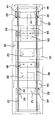
도 1은 바를 고정시키지 않은 블로-몰딩 장치의 하부 베이스 프레임이 참조번호(10)으로 표시되고, 그 베이스 프레임상에 2개의 베어링 받침대(12, 14)가 2개의 평행한 원통형 막대(16) 또는 슬라이딩 레일상에 수평방향으로 변위가능하게 장착된다. 각각의 베어링 받침대(12, 14)는 신속하게 분리가능한 방식으로 각 블로 절반부(22, 24)가 고정되는 성형 장착판(18, 20)을 운반한다. 나란히 측면으로 배치된 블로-몰드 절반부(22, 24)에서, (왼쪽 측면상에) 상부 및 하부 정지 로킹 장치 절반부(26, 28) 및 (오른쪽 측면상에) 반대로 배치된 로킹 장치의 상응하는 상부 및 하부의 유압식으로 변위가능한 로킹 장치 절반부(30, 32)가 상기 성형 장착판(18, 20)에 분리가능하게 고정된다. 이 경우에 상기 블로-몰드 절반부(22, 24)의 로킹 시스템은 이동 장치의 구동과는 완전히 무관하게 만들어질 수 있고 블로-몰딩 장치 및 블로 중공 몸체의 크기에 따라서 (약 50mm의 전후 왕복 운동하는) 2개 또는 (도시된 바와같이) 4개 짧은 전후 왕복 운동하는 유압 실린더를 포함한다. 장점적으로, 힘의 밀폐계(힘의 다각형)가 로킹 시스템 내에 존재한다. 블로-몰딩이 개방될 때, 클리어런스 내에서 방해가 되도록 돌출하여 예를 들면, 완성된 제품의 퇴거(removal)를 방해하는 로킹요소가 존재하지 않도록, 이 때의 로킹 시스템의 정방향 로킹은 사실상 몰드 분할면에서 일어난다.1 shows the lower base frame of the blow-molding apparatus without fixing the bar by the
블로-몰드 절반부의 빠른 앞 뒤 이동(빠른 횡단)을 위한 실제 전달 장치(34)는 하부 프레임(10)에서 베어링 받침대(12, 14) 아래에 정렬된다. 상기 전달 장치(34)는 서로 독립적이고 동일 형태의 적어도 2개의 분리된 구동 조립체를 포함하고, 몰드 지지판(18, 20)을 운반하는 각 외부 베어링 받침대(12, 14)는 이러한 구동 조립체의 적어도 하나를 구비한다.The
바람직한 실시예에 따라서, 각 구동 조립체는 결합 수단(36)으로서 하우징에 고정된 (회전식으로 나사산이 형성된 스핀들이 아닌) 정지식으로 나사산이 형성된 막대를 포함하고, 각 외부 베어링 받침대(12, 14)에 고정되어 그와 함께 변위가능한 모터는, 상기 모터에 회전가능하게 장착된 맞물림 수단인 회전하는 나사산이 형성된 너트와 함께 나사산이 형성된 막대상에 직접 정렬되고 상기 나사산이 형성된 너트를 통하여 나사산이 형성된 막대에 정방향 로킹 방법으로 동작적으로 결합된다.According to a preferred embodiment, each drive assembly comprises a stationary threaded rod (rather than a rotary threaded spindle) fixed to the housing as coupling means 36, each
결합 수단(36)(여기서 나사산이 형성된 막대)는 도시된 바와같이-하나는 다른 하나 아래에 또는 프레임(10)에서 2개의 평면으로 정렬될 수 있다. 보다 작은 장치의 경우에서, 상기 결합 수단은 후미 측면으로 오프세트되어, 가령, 블로 굴대 장치에 대해 좀더 많은 공간을 이용할 수 있도록 한다.The coupling means 36 (here threaded rods) can be arranged as shown-one below the other or in two planes in the
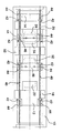
제 2도에 도시된 본 발명에 따른 2개-스테이션 장치의 경우에서, 하나의 스테이션(예를들면 왼쪽 스테이션)은 2개의 블로-몰드 절반부(24, 54), 그 아래에 배치된 블로 굴대 장치(46), 2개의 몰드 지지판(20, 25) 및 몰드 지지판(20)을 운반하는 외부 베어링 받침대(14) 및 중앙 몰드 지지판(50)이 장착된 중앙 베어링 받침대(도면에 도시되지 않았음)를 포함한다. 동일 방법으로, 다른(오른쪽) 스테이션은 2개의 블로-몰드 절반부(22, 52), 그 아래에 배치된 블로 굴대 장치(46), 2개의 몰드 지지판(18, 50) 및 또한 몰드 지지판(18)을 운반하는 외부 베어링 받침대(12) 및 중앙 몰드 지지판(50)을 운반하는 중앙 베어링 받침대(48)(도면에 도시되지 않았음)를 포함한다. 각 블로-몰드 절반부(54, 52)가 양쪽 스테이션 모두에 속하는 이러한 중앙 몰드 지지판(50) 양측상에 장착된다. 블로-몰드 절반부(54)는 왼쪽 스테이션의 오른쪽 블로-몰드 절반부를 구성하고, 블로-몰드 절반부(52)는 오른쪽 스테이션의 왼쪽 블로-몰드 절반부를 구성한다.In the case of a two-station apparatus according to the invention shown in FIG. 2, one station (eg left station) has two blow-molded
이러한 장치에서 오직 2개의 외부 베어링 받침대(12, 14)만이 구동 조립체를 구비하고, 각 구동 조립체는, 프레임(10)에서 서로 평행하게 고정된 2개의 나사산이 형성된 막대(40)중 하나상에 회전가능하고 나사산이 형성된 너트(42)와 함께 서로 평행하게 정렬되고 고정된 2개의 전기적인 중공 샤프트 모터(44)을 포함한다. 이러한 실시예의 경우에는, 나사산이 형성된 막대(40)는 한 평면에 서로 평행하게 상기 프레임(10)에 측면으로 각각 정렬되어 스프레딩 및 턴-아웃 장치를 갖는 블로 굴대 장치(46)에 대하여 충분한 공간을 이용할 수 있도록 한다. 보다 작은 또는 한 스테이션 장치의 경우에는, 상기 결합 수단은 한 피이스의 연속적인 나사산이 형성된 막대 또는 랙으로 구성되고, 한편 보다 긴 또는 다중 스테이션 장치의 경우에는, 상기 프레임의 양쪽 긴 측면상으로 연장되는 결합 수단이 한 라인에서 차례로 정렬된 다수의 피이스(나사산이 형성된 막대, 랙등)로 구성된다.In this arrangement only two outer bearing pedestals 12, 14 have drive assemblies, each drive assembly rotating on one of two threaded
동작에서, 열가소성 재료의 관형 패리슨이 도 2에서 동시에 개방되는 오른쪽 스테이션의 블로-몰드 절반부(52, 22)사이에 압출성형(extrude)된다. 이러한 과정에서, 관의 하부 단부는 블로 굴대 장치(46)로 하강하고 개방되어 이격된 상태를 유지한다. 블로-몰드 절반부(52, 22)는 함께 이동되고 닫힌다. 이것은 오른쪽 블로-몰드 절반부(22)에 대해서는 베어링 받침대(12)에 고정되고 나사산이 형성된 슬리브(42)를 가지는 2개의 중공 샤프트 모터에 의하여, 그리고, 왼쪽 블로-몰드 절반부(52)에 대해서는 베어링 받침대(14)에 고정되고 나사산이 형성된 슬리브(42)을 가지는 2개의 중공 샤프트 모터(44)에 의하여 이루어진다. 왼쪽 스테이션의 2개의 블로-몰드 절반부(24, 54)(sic)는 이 시점에서 상응하는 로킹 장치에 의하여 닫히거나 또는 잠기거나 결합된다. 그 사이에 배치된 블로 굴대 장치(46)은 언급한 바와같이 자유롭게 변위가능하고 자신의 지지 장치에 의하여 어떤 위치에서 감기거나 정지시킬 수 있다. 오른쪽 스테이션(블로-몰드 절반부(52, 55))이 닫힐 때, 양쪽 스테이션의 전체 결합된 유니트는 성형 분리 라인 및 성형 굴대 장치가 관형 패리슨용 압출다이 아래에 정확하게 배치될 때까지 오른쪽으로 이동된다. 왼쪽 스테이션의 2개의 블로-몰드 절반부(24, 54)의 로킹 장치는 현재 풀려 있거나 개방되는 즉시, 상기 2개의 블로-몰드 절반부(24, 54)는 이격된다. 왼쪽-블로장치 절반부(24)에 대하여 이것은 베어링 받침대(14)에 고정된 2개의 중공 샤프트 모터에 의하여 이루어지고, 오른쪽 블로-몰드 절반부(54)에 대하여 이것은 베어링 받침대(12)에 고정된 2개의 중공 샤프트 모터에 의하여 이루어지는 동시에, 오른쪽 스테이션이 닫히거나 상기 블로-몰드 절반부(52, 22)가 잠금 장치에 의하여 잠기거나 결합된다. 2개의 블로-몰드 절반부(24, 54)의 개방후에, 완성된 제품이 제거되고 새로운 관형 패리슨이 상기 블로-몰드 절반부사이에서 압출성형된다. 이러한 기능적인 스퀀스는 원칙적으로 3개 또는 그 이상의 스테이션을 가진 장치의 경우에 동일 방법으로 발생된다.In operation, the tubular parison of the thermoplastic material is extruded between the blow-molded
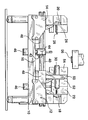
도 3에 도시된 2개 스테이션 블로-몰딩 장치의 경우에, 2개 블로 굴대 장치(46)에는 1개 또는 보다 큰 장치의 경우에 2개의 작은 전기 중공 샤프트 모터(44) 및 정방향 로킹 나사산이 형성된 슬리브(42)가 추가로 구비된다. 그 결과 각 블로 굴대 장치(46)는 상기 블로-몰드 절반부가 개방될 때 요구된 바와같이 자유롭게 이동된다. 상기 블로-몰드 절반부가 닫히거나 또는 양쪽 스테이션이 함께 이동될 때, 블로 굴대 장치(46)의 모터는 구동되지않고 그와 함께 비활성적으로 변위되거나 또는 전체 유니트에 대한 부가적인 구동기로 작용하는 어느 하나로 전환될 수 있다.In the case of the two station blow-molding device shown in FIG. 3, the two
오른쪽 스테이션에서, 중공 샤프트 모터(44)를 갖는 블로 굴대 장치(46)는 중앙의 중간 위치 오른쪽으로부터 왼쪽 블로-몰드 절반부(52)에 이르기까지 이동될 수 있다는 것을 알 수 있다. 이미 언급한 바와 같이 이러한 처리 공정은 전문적인 또는 비대칭적인 블로-몰딩의 생산을 위하여 특히 아주 중요하다.At the right station, it can be seen that the
도 4에 도시된 2개 스테이션 블로-몰딩 장치는 개방 블로-몰드 절반부(여기서 24, 54)가 나사산이 형성된 막대(40)의 자유롭게 이용할 수 있는 경로 길이에 의하여 아주 멀리 떨어지게 이동할 수 있다는 것을 명확히 나타낸다. 이것은 예를 들어, 청소 목적, 수리 작업, 성형의 빠른 교체에 아주 유리하다. 왼쪽 스테이션의 중공 샤프트 모터(44)를 가진 블로 굴대 장치(46)는 이 경우에 관형 패리슨에 대하여 압출다이(56, extrusion die) 아래의 중간 위치로부터 떨어진 개방 블로-몰드 절반부(24, 54) 사이의 어떤 요구된 위치로 이동되고 고정된다. 예를 들어, 수리 작업 또는 성형의 교체를 위하여, 만약 블로 굴대 장치가 전체적으로 방해가 되지 않는 한쪽 측면으로 이동할 수 있다면 매우 유용할 수 있을 것이다.The two station blow-molding apparatus shown in FIG. 4 makes it clear that the open blow-molded halves (here 24 and 54) can be moved very far away by the freely available path length of the threaded
본 발명에 따르면 블로-몰딩 장치는 3개, 4개 또는 그 이상의 스테이션을 가진 장치로서 도 2, 3 및 4에 도시된 2개-스테이션과 동일한 방법으로 만들어질 수 있고, 각 경우에는 오직 2개의 외부 베어링 받침대(12, 14)는 구동 조립체를 구비하고 한편 다수의 중앙 베어링 받침대(48)는 그들 자신의 어떤 구동기도 없이 상기 프레임상에 자유롭게 변위될 수 있고, 양측상에 각 블로-몰드 절반부(52, 54)를 갖는 오직 하나의 몰드 지지판(50)을 구비한다. 단지 블로-몰딩 장치는 자신의 구동기 또는 중공 샤프트 모터를 구비할 수 있다.According to the invention the blow-molding apparatus can be made in the same way as the two-stations shown in Figs. 2, 3 and 4, with three, four or more stations, in which case only two The outer bearing pedestals 12 and 14 have a drive assembly while a number of central bearing pedestals 48 can be freely displaced on the frame without any of their own drivers, and each blow-molded half on both sides Only one
지금까지 기술적으로 가능하고 적절한 상기 언급한 특징에 대하여 요구에 따라서 서로 조합하거나 또는 서로 해체할 수 있다는 것은 말할 필요가 없다.Needless to say, technically possible and suitable above mentioned features can be combined or disassembled with one another on demand.
본 발명은 기계적으로 동시적인 장치 및 상기 블로-몰드 절반부의 직접적인 기계적 결합이 없고, 상기 블로-몰드 절반부가 서로에 대하여 독립적으로 이동할 수 있는, 초기에 언급한 블로-몰딩 장치를 더 발전시키는 것으로서, 전체 시스템에 유극이 없고, 유압 시스템(유압 탱크, 라인, 압력 펌프, 오일)이 필요없고, 전달 장치가 조용하고 진동이 없이 동작하고, 모든 베어링-받침대 모터가 간단한 마스터-슬래이브 시스템에 의하여 제어되고, 다중-스테이션 장치(2개, 3개, 4개 또는 그 이상의 스테이션)의 경우에, 별도의 블로-몰딩 로킹시스템에 의한 결합에 의하여 오직 2개의 외부 블로-몰드 절반부 또는 구동기(전기 스핀들 모터)를 구비할 필요가 있는 관련 베어링 받침대, 내부 블로-몰드 절반부 또는 그들 사이에 배치된 블로-몰드 절반부는 외부 구동 블로-몰드 절반부에 의하여 그들과 함께 이동되는 효과를 가져온다. 특히, 본 발명은 전문적인 또는 비대칭적인 플라스틱 부품의 생산에 대하여 특히 유용하다.The present invention further develops an earlier mentioned blow-molding apparatus in which there is no mechanically simultaneous apparatus and direct mechanical coupling of the blow-molded halves, and in which the blow-molded halves can move independently of one another. There is no play in the whole system, no hydraulic system (hydraulic tank, line, pressure pump, oil), transmission device is quiet and vibration-free, all bearing-base motors are controlled by a simple master-slave system And in the case of a multi-station device (two, three, four or more stations), only two external blow-molded halves or actuators (electric spindles) by coupling by separate blow-molding locking systems Associated bearing pedestals, inner blow-mould halves, or blow-mould halves disposed between them, which need to be provided with The effect is that they are moved with them by the blow-molded halves. In particular, the present invention is particularly useful for the production of professional or asymmetric plastic parts.
도 1은 본 발명에 따른 한 스테이션 블로-몰딩 장치의 측면도;1 is a side view of one station blow-molding apparatus according to the present invention;
도 2는 본 발명에 따른 2개의 스테이션 블로-몰딩 장치의 평면도;2 is a plan view of a two station blow-molding apparatus according to the present invention;
도 3은 본 발명에 따른 2개 스테이션 블로-몰딩 장치의 추가 실시예의 평면도;3 is a plan view of a further embodiment of a two station blow-molding apparatus according to the present invention;
도 4는 본 발명에 따른 2개-스테이션의 블로우 성형장치의 측면도.4 is a side view of a two-station blow molding apparatus according to the present invention;
* 도면의 주요 부분에 대한 부호의 설명** Explanation of symbols for main parts of the drawing
10 : 베이스 프레임 12 : 베어링 받침대(오른쪽)10: base frame 12: bearing support (right)
14 : 베어링 받침대(왼쪽) 16 : 원통형 로드 (10)14: bearing pedestal (left) 16: cylindrical rod (10)
18 : 몰드 지지판(오른쪽) 20 : 몰드 지지판(왼쪽)18: mold support plate (right) 20: mold support plate (left)
22 : 블로-몰드 절반부(오른쪽)22: blow mold half (right)
24 : 블로-몰드 절반부 (왼쪽)24: blow mold half (left)
26 : 상부 로킹 절반부 28 : 하부 로킹 절반부26: upper locking half 28: lower locking half
30 : 상부 유압식 로킹 절반부 32 : 하부 유압식 로킹 절반부30: upper hydraulic locking half 32: lower hydraulic locking half
34 : 전달 장치 36 : 결합 수단(10/38)34
38 : 구동 모터(38/12-14) 40 : 나사산이 형성된 막대38: drive motor (38 / 12-14) 40: threaded rod
42 : 회전가능한 나사산이 형성된 너트 44 : 전기 중공 샤프트 모터42: rotatable threaded nut 44: electric hollow shaft motor
46 : 블로 굴대 장치 48 : 중앙 베어링 받침대46 blow mandrel device 48: center bearing support
50 : 중앙 성형 지지대50: center forming support
52 : 중앙 블로-몰드 절반부 (오른쪽)52: center blow mold half (right)
54 : 중앙 블로-몰드 절반부(왼쪽) 56 : 압출다이(extrusion die)54: center blow mold half (left) 56: extrusion die
Claims (6)
Applications Claiming Priority (2)
| Application Number | Priority Date | Filing Date | Title |
|---|---|---|---|
| DE29619781 | 1996-11-15 | ||
| DE29619781U DE29619781U1 (en) | 1996-11-15 | 1996-11-15 | Blow molding machine |
Publications (2)
| Publication Number | Publication Date |
|---|---|
| KR19980042356A KR19980042356A (en) | 1998-08-17 |
| KR100515758B1 true KR100515758B1 (en) | 2005-12-09 |
Family
ID=8031920
Family Applications (1)
| Application Number | Title | Priority Date | Filing Date |
|---|---|---|---|
| KR1019970059585A KR100515758B1 (en) | 1996-11-15 | 1997-11-13 | Blow-Moulding Machine |
Country Status (9)
| Country | Link |
|---|---|
| US (1) | US5975881A (en) |
| JP (1) | JP4112658B2 (en) |
| KR (1) | KR100515758B1 (en) |
| CN (1) | CN1191176A (en) |
| AT (1) | AT409243B (en) |
| BR (1) | BR9705714A (en) |
| DE (2) | DE29619781U1 (en) |
| IT (1) | IT1296432B1 (en) |
| TW (1) | TW424044B (en) |
Families Citing this family (30)
| Publication number | Priority date | Publication date | Assignee | Title |
|---|---|---|---|---|
| US6499988B1 (en) * | 1997-02-25 | 2002-12-31 | Kao Corporation | Blow molding machine |
| DE19912116A1 (en) * | 1999-03-18 | 2000-09-21 | Kautex Maschinenbau Gmbh | Blow molding of hollow thermoplastic products from preforms using a closure frame with a central and two outer plates carrying molds with locking systems and a movement synchronizing mechanism |
| DE19927138C2 (en) * | 1999-06-15 | 2002-02-28 | Fischer W Mueller Blasformtech | Method and device for closing and opening the molds of a plastic processing machine |
| DE19932741C2 (en) * | 1999-07-14 | 2002-06-27 | Fischer W Mueller Blasformtech | Method and device for closing and opening the tool of a plastics processing machine |
| US6334768B1 (en) * | 1999-08-11 | 2002-01-01 | Husky Injection Molding Systems Ltd. | Blow molding clamp arrangement |
| ATE254993T1 (en) | 1999-11-11 | 2003-12-15 | Mauser Werke Gmbh & Co Kg | BLOW MOLDING MACHINE WITH ELECTRIC MOTOR DIRECT DRIVE FOR OPENING AND CLOSING MOVEMENT AND LOCKING MOVEMENT |
| US6834603B1 (en) | 2002-03-05 | 2004-12-28 | Atlanta Attachment Company | Attachment gusset with ruffled corners and system for automated manufacture of same |
| FR2856333B1 (en) * | 2003-06-19 | 2005-08-26 | Sidel Sa | MOLDING DEVICE FOR MANUFACTURING CONTAINERS OF THERMOPLASTIC MATERIAL |
| FR2856334B1 (en) * | 2003-06-19 | 2005-08-26 | Sidel Sa | MOLDING DEVICE FOR MANUFACTURING CONTAINERS OF THERMOPLASTIC MATERIAL |
| ITMI20040835A1 (en) * | 2004-04-27 | 2004-07-27 | Magic Mp Spa | MACHINE FOR FORMING PLASTIC CONTAINERS WITH LINEAR MOTOR FOR HANDLING OF THE MOLD HOLDER GROUP |
| US7984681B1 (en) | 2007-11-20 | 2011-07-26 | Atlanta Attachment Company | Automatic panel sewing and flanging system |
| US7850443B2 (en) * | 2007-11-23 | 2010-12-14 | Dme Company Llc | Apparatus for injection molding |
| EP2263855B1 (en) * | 2008-12-19 | 2013-11-06 | Krones AG | Electrically operated blow-moulding machine and the method |
| EP2251180A1 (en) * | 2009-05-13 | 2010-11-17 | Uniloy Milacron Germany GmbH | Assembly and method for electromechanical drive for mould closing and calibration blow pins in blow moulding machines |
| DE102009039695B4 (en) * | 2009-09-02 | 2020-08-13 | Krones Aktiengesellschaft | Method and device for assembling and / or disassembling blow molds |
| CN101890805B (en) * | 2010-04-13 | 2012-07-11 | 苏州同大机械有限公司 | Magnetic mold closing device for hollow plastic product molding machine |
| JP5631669B2 (en) * | 2010-09-03 | 2014-11-26 | 小島プレス工業株式会社 | Multiple press molding equipment |
| DE102011007280A1 (en) | 2011-04-13 | 2012-10-18 | Krones Aktiengesellschaft | Container treatment machine and method for container treatment |
| CN102275261A (en) * | 2011-05-04 | 2011-12-14 | 苏州威凯精密模具有限公司 | Injection mold for threaded products |
| DE102011079078A1 (en) | 2011-07-13 | 2013-01-17 | Krones Ag | Aster feeder for treatment machines |
| DE102011079077A1 (en) | 2011-07-13 | 2013-01-17 | Krones Aktiengesellschaft | Blowing machine for plastic containers |
| DE102012100161A1 (en) * | 2012-01-10 | 2013-07-11 | Extraplast Maschinen Gmbh | Blow molding system and method for blow molding of hollow bodies |
| DE102012100156A1 (en) * | 2012-01-10 | 2013-07-11 | Extraplast Maschinen Gmbh | Blow molding system and method for blow molding of hollow bodies |
| TW201441010A (en) * | 2013-04-24 | 2014-11-01 | Jih Huang Machinery Ind Co Ltd | All-electric type hollow molding machine |
| CN104943136A (en) * | 2014-03-27 | 2015-09-30 | 东莞市中顺包装容器实业有限公司 | Servo direct-locking type mold closing mechanism of bottle blowing machine |
| KR102163446B1 (en) * | 2015-03-18 | 2020-10-08 | 닛세이 에이. 에스. 비 기카이 가부시키가이샤 | Biaxial stretching and blow molding device |
| CN107297884B (en) * | 2017-08-04 | 2023-04-18 | 台州市祥珑食品容器科技股份有限公司 | Blow mold opening and closing device and blow molding machine |
| CN108435662A (en) * | 2018-05-16 | 2018-08-24 | 贵州大学 | A kind of cleaning device for mold production and processing |
| CN110001032B (en) * | 2019-04-30 | 2024-04-09 | 山东通佳智能装备有限公司 | Mould locking device of blow molding machine |
| CN115308300B (en) * | 2022-10-11 | 2022-12-20 | 湖南省特种设备检验检测研究院 | Boiler water wall pipe defect eddy current testing device |
Family Cites Families (10)
| Publication number | Priority date | Publication date | Assignee | Title |
|---|---|---|---|---|
| DE1604575C3 (en) * | 1966-02-10 | 1975-11-20 | Kautex Werke Reinold Hagen Gmbh, 5300 Bonn-Holzlar | Device for the production of hollow bodies made of thermoplastic material in the blow molding process |
| US3465387A (en) * | 1967-06-12 | 1969-09-09 | Improved Machinery Inc | Two-stage clamping machine |
| US4421472A (en) * | 1981-08-31 | 1983-12-20 | R & B Machine Tool Company | Clamp for blow molding machine |
| DE3416871C3 (en) * | 1984-05-08 | 1995-11-09 | Mauser Werke Gmbh | Mold closing device |
| DE3448497C2 (en) * | 1984-05-08 | 1997-05-22 | Mauser Werke Gmbh | Blow molding machine |
| US4998873A (en) * | 1988-10-03 | 1991-03-12 | R & B Machine Tool Company | Mold station for a blow molding machine |
| DE9206649U1 (en) * | 1992-05-15 | 1993-09-16 | Mauser Werke Gmbh | Blow molding machine |
| DE19508525A1 (en) * | 1995-03-10 | 1996-09-12 | Kautex Werke Gmbh | Method and device for producing hollow bodies from thermoplastic material |
| DE19516125C1 (en) * | 1995-05-03 | 1996-06-05 | Battenfeld Fischer Blasform | Tool closure on plastics processing machine process equipment |
| US5645873A (en) * | 1995-08-14 | 1997-07-08 | Cincinnati Milacron Inc. | Electromechanical drive assembly for an accumulator head |
-
1996
- 1996-11-15 DE DE29619781U patent/DE29619781U1/en not_active Expired - Lifetime
-
1997
- 1997-10-29 DE DE19747698A patent/DE19747698C2/en not_active Expired - Lifetime
- 1997-11-04 TW TW086116321A patent/TW424044B/en not_active IP Right Cessation
- 1997-11-12 AT AT0191797A patent/AT409243B/en not_active IP Right Cessation
- 1997-11-13 KR KR1019970059585A patent/KR100515758B1/en not_active IP Right Cessation
- 1997-11-14 IT IT97MI002535A patent/IT1296432B1/en active IP Right Grant
- 1997-11-14 US US08/970,369 patent/US5975881A/en not_active Expired - Fee Related
- 1997-11-14 BR BR9705714A patent/BR9705714A/en active Search and Examination
- 1997-11-15 CN CN97125272A patent/CN1191176A/en active Pending
- 1997-11-17 JP JP31528197A patent/JP4112658B2/en not_active Expired - Lifetime
Also Published As
| Publication number | Publication date |
|---|---|
| CN1191176A (en) | 1998-08-26 |
| DE29619781U1 (en) | 1997-01-02 |
| US5975881A (en) | 1999-11-02 |
| TW424044B (en) | 2001-03-01 |
| BR9705714A (en) | 1999-05-18 |
| IT1296432B1 (en) | 1999-06-25 |
| DE19747698C2 (en) | 2002-10-31 |
| DE19747698A1 (en) | 1998-05-20 |
| AT409243B (en) | 2002-06-25 |
| KR19980042356A (en) | 1998-08-17 |
| JPH10175251A (en) | 1998-06-30 |
| ITMI972535A1 (en) | 1999-05-14 |
| ATA191797A (en) | 2001-11-15 |
| JP4112658B2 (en) | 2008-07-02 |
Similar Documents
| Publication | Publication Date | Title |
|---|---|---|
| KR100515758B1 (en) | Blow-Moulding Machine | |
| CA2244581C (en) | Apparatus for manufacturing injection-moulded articles from at least two plastic melts | |
| KR100471925B1 (en) | Apparatus for manufacturing thermoplastic plastic pipes characterized by cross-sectional shapes | |
| US8573963B2 (en) | Adjustable multiple-piece cam track | |
| US3843286A (en) | Blow molding apparatus | |
| EP1868767B1 (en) | Method and device for positioning a component | |
| KR100269800B1 (en) | Blow molding machine | |
| AU2011312398B2 (en) | Rotary moulding machines | |
| CN107530947B (en) | Blow moulding machine for containers made of polymer material | |
| KR900007347B1 (en) | Blow-molding apparatus for molding hollow articles os synthetic resin | |
| KR101571657B1 (en) | Device for producing blowmolded container products from plastic material | |
| WO2001034368A3 (en) | Blow-molding machine with an electric motor direct drive for performing the opening and closing movement and the latching movement | |
| US7874828B2 (en) | Machine for moulding plastic containers using means for moving the mould-support unit comprising two in-line connecting rods | |
| US3877861A (en) | Blow moulding machine with cam controlled reciprocating carriage | |
| JP2003504226A5 (en) | ||
| ES2319391T3 (en) | MOLDING MACHINE FOR BLOWING RECIPIENTS MADE OF A PLASTIC MATERIAL WITH ELECTRIC TYPE ACTUATING DEVICES. | |
| US6514452B1 (en) | Double-mold blow-molding system and method of use | |
| US20050238754A1 (en) | Machine for forming plastic containers with a linear motor for moving the mould-support unit | |
| EP1484160A1 (en) | Apparatus for blow moulding of containers with a linear motor driven stretching rod | |
| EP3743256A1 (en) | Injection molding device | |
| US5501591A (en) | Blow-moulding machine with calibration stations | |
| US4673347A (en) | Multiple station, multiple clamp assembly blow molding machines | |
| EP1818158B1 (en) | Machine for moulding plastic containers with linear-rack means for moving the mould-carrying unit | |
| JP2002273776A (en) | Method and device for manufacture of thermoplastic plastic pipe having peculiar property on lateral contour | |
| US5971741A (en) | Blow pin assembly for a rotary blow molding machine |
Legal Events
| Date | Code | Title | Description |
|---|---|---|---|
| A201 | Request for examination | ||
| E902 | Notification of reason for refusal | ||
| E701 | Decision to grant or registration of patent right | ||
| GRNT | Written decision to grant | ||
| FPAY | Annual fee payment |
Payment date: 20120830 Year of fee payment: 8 |
|
| FPAY | Annual fee payment |
Payment date: 20130827 Year of fee payment: 9 |
|
| FPAY | Annual fee payment |
Payment date: 20140901 Year of fee payment: 10 |
|
| FPAY | Annual fee payment |
Payment date: 20150902 Year of fee payment: 11 |
|
| FPAY | Annual fee payment |
Payment date: 20160830 Year of fee payment: 12 |
|
| LAPS | Lapse due to unpaid annual fee |