KR100456765B1 - Method for attaching a rotor blade to an integrally bladed rotor - Google Patents
Method for attaching a rotor blade to an integrally bladed rotor Download PDFInfo
- Publication number
- KR100456765B1 KR100456765B1 KR1019970059204A KR19970059204A KR100456765B1 KR 100456765 B1 KR100456765 B1 KR 100456765B1 KR 1019970059204 A KR1019970059204 A KR 1019970059204A KR 19970059204 A KR19970059204 A KR 19970059204A KR 100456765 B1 KR100456765 B1 KR 100456765B1
- Authority
- KR
- South Korea
- Prior art keywords
- blade
- rotor
- stub
- die
- platform
- Prior art date
Links
Images

Classifications
-
- B—PERFORMING OPERATIONS; TRANSPORTING
- B23—MACHINE TOOLS; METAL-WORKING NOT OTHERWISE PROVIDED FOR
- B23P—METAL-WORKING NOT OTHERWISE PROVIDED FOR; COMBINED OPERATIONS; UNIVERSAL MACHINE TOOLS
- B23P6/00—Restoring or reconditioning objects
- B23P6/002—Repairing turbine components, e.g. moving or stationary blades, rotors
- B23P6/005—Repairing turbine components, e.g. moving or stationary blades, rotors using only replacement pieces of a particular form
-
- F—MECHANICAL ENGINEERING; LIGHTING; HEATING; WEAPONS; BLASTING
- F01—MACHINES OR ENGINES IN GENERAL; ENGINE PLANTS IN GENERAL; STEAM ENGINES
- F01D—NON-POSITIVE DISPLACEMENT MACHINES OR ENGINES, e.g. STEAM TURBINES
- F01D5/00—Blades; Blade-carrying members; Heating, heat-insulating, cooling or antivibration means on the blades or the members
- F01D5/005—Repairing methods or devices
-
- F—MECHANICAL ENGINEERING; LIGHTING; HEATING; WEAPONS; BLASTING
- F01—MACHINES OR ENGINES IN GENERAL; ENGINE PLANTS IN GENERAL; STEAM ENGINES
- F01D—NON-POSITIVE DISPLACEMENT MACHINES OR ENGINES, e.g. STEAM TURBINES
- F01D5/00—Blades; Blade-carrying members; Heating, heat-insulating, cooling or antivibration means on the blades or the members
- F01D5/30—Fixing blades to rotors; Blade roots ; Blade spacers
- F01D5/3061—Fixing blades to rotors; Blade roots ; Blade spacers by welding, brazing
-
- F—MECHANICAL ENGINEERING; LIGHTING; HEATING; WEAPONS; BLASTING
- F01—MACHINES OR ENGINES IN GENERAL; ENGINE PLANTS IN GENERAL; STEAM ENGINES
- F01D—NON-POSITIVE DISPLACEMENT MACHINES OR ENGINES, e.g. STEAM TURBINES
- F01D5/00—Blades; Blade-carrying members; Heating, heat-insulating, cooling or antivibration means on the blades or the members
- F01D5/34—Rotor-blade aggregates of unitary construction, e.g. formed of sheet laminae
-
- F—MECHANICAL ENGINEERING; LIGHTING; HEATING; WEAPONS; BLASTING
- F05—INDEXING SCHEMES RELATING TO ENGINES OR PUMPS IN VARIOUS SUBCLASSES OF CLASSES F01-F04
- F05D—INDEXING SCHEME FOR ASPECTS RELATING TO NON-POSITIVE-DISPLACEMENT MACHINES OR ENGINES, GAS-TURBINES OR JET-PROPULSION PLANTS
- F05D2230/00—Manufacture
- F05D2230/80—Repairing, retrofitting or upgrading methods
-
- Y—GENERAL TAGGING OF NEW TECHNOLOGICAL DEVELOPMENTS; GENERAL TAGGING OF CROSS-SECTIONAL TECHNOLOGIES SPANNING OVER SEVERAL SECTIONS OF THE IPC; TECHNICAL SUBJECTS COVERED BY FORMER USPC CROSS-REFERENCE ART COLLECTIONS [XRACs] AND DIGESTS
- Y10—TECHNICAL SUBJECTS COVERED BY FORMER USPC
- Y10T—TECHNICAL SUBJECTS COVERED BY FORMER US CLASSIFICATION
- Y10T29/00—Metal working
- Y10T29/49—Method of mechanical manufacture
- Y10T29/49316—Impeller making
- Y10T29/49318—Repairing or disassembling
-
- Y—GENERAL TAGGING OF NEW TECHNOLOGICAL DEVELOPMENTS; GENERAL TAGGING OF CROSS-SECTIONAL TECHNOLOGIES SPANNING OVER SEVERAL SECTIONS OF THE IPC; TECHNICAL SUBJECTS COVERED BY FORMER USPC CROSS-REFERENCE ART COLLECTIONS [XRACs] AND DIGESTS
- Y10—TECHNICAL SUBJECTS COVERED BY FORMER USPC
- Y10T—TECHNICAL SUBJECTS COVERED BY FORMER US CLASSIFICATION
- Y10T29/00—Metal working
- Y10T29/49—Method of mechanical manufacture
- Y10T29/49316—Impeller making
- Y10T29/49336—Blade making
- Y10T29/49339—Hollow blade
- Y10T29/49341—Hollow blade with cooling passage
- Y10T29/49343—Passage contains tubular insert
Abstract
본 발명의 디스크를 구비하는 일체식 블레이드형 로터상의 로터 블레이드를 교체하는 방법은 ⓐ 상기 디스크로부터 연장되는 로터 블레이드의 스터브 부분을 잔류시키고 손상된 로터 블레이드를 제거하는 단계로서, 상기 로터 블레이드의 상기 스터브 부분은 전연부, 후연부, 흡입 측부 및 압력 측부를 구비하는, 상기 로터 블레이드 제거 단계와, ⓑ 압력 측부 및 흡입 측부를 구비하는 다이를 제공하는 단계로서, 상기 각 측부는 플랫폼 트로프를 포함하는, 상기 다이 제공 단계와, ⓒ 상기 다이를 상기 로터 블레이드 스터브에 고정하는 단계로서, 상기 다이의 압력 측부는 상기 스터브의 상기 압력 측부상에 위치되며, 상기 다이의 상기 흡입 측부는 상기 스터브의 상기 흡입 측부상에 위치되는, 상기 고정 단계와, ⓓ 상기 로터 블레이드 스터브의 일부분을 상기 플랫폼 트로프내로 압출하여 플랫폼을 형성하는 단계와, ⓔ 로터 블레이드를 상기 플랫폼에 부착하는 단계를 포함한다.A method for replacing a rotor blade on an integrated blade-shaped rotor with a disk of the present invention comprises the steps of: remaining of the stub portion of the rotor blade extending from the disk and removing the damaged rotor blade, the stub portion of the rotor blade. Is a step of removing the rotor blade, comprising a leading edge, a trailing edge, a suction side and a pressure side, and providing a die having a pressure side and a suction side, each side comprising a platform trough. Providing a die and securing the die to the rotor blade stub, wherein the pressure side of the die is located on the pressure side of the stub, and the suction side of the die is on the suction side of the stub. The fixing step, ⓓ a portion of the rotor blade stub To a step and, ⓔ attaching a rotor blade to said platform for extrusion to form a platform into the platform troughs.
Description
본 발명은 일반적으로 가스 터빈 엔진용 일체식 블레이드형 로터에 관한 것이며, 특히 일체식 블레이드형 로터를 제조 또는 수리하는 방법에 관한 것이다.The present invention relates generally to an integrated blade type rotor for a gas turbine engine, and more particularly to a method for manufacturing or repairing an integrated blade type rotor.
가스 터빈 엔진의 압축기 및 터빈 부분은 통상적으로 다수의 로터 및 스테이터 베인 조립체를 포함한다. 로터 조립체는 압축기 부분을 통해 통과하는 중심 가스내로 일을 부여하고, 터빈 부분을 통해 통과되는 중심 가스로부터 일을 취출하도록 설계된다. 스테이터 베인 조립체는 로터 조립체에 들어가거나 빠져나가도록 중심 가스를 배향시키는데 도움을 주고, 이에 의해 엔진의 효율을 증가시킨다.The compressor and turbine portions of a gas turbine engine typically include a plurality of rotor and stator vane assemblies. The rotor assembly is designed to impart work into the central gas passing through the compressor portion and withdraw the work from the central gas passed through the turbine portion. The stator vane assembly helps to orient the center gas to enter or exit the rotor assembly, thereby increasing engine efficiency.
각 로터 조립체는 디스크와, 이 디스크에 부착된 다수의 블레이드를 포함하며, 이들 블레이드는 디스크의 원주 둘레에 균일하게 분포되어 있다. 역사적으로,Each rotor assembly includes a disk and a plurality of blades attached to the disk, which blades are evenly distributed around the circumference of the disk. Historically,
블레이드는 "크리스마스트리"형 부착과 같은 기계적 수단에 의해 디스크에 부착되며, 크리스마스트리형 블레이드 루트부는 디스크내의 맞물림 리세스내에 수납된다. 블레이드를 기계적으로 부착하는 장점은 블레이드가 손상되거나 결함이 발견된 경우에 쉽게 교체할 수 있다는 것이다. 로터 블레이드를 기계적으로 부착하는 단점은 루트부 디스크가 조립체의 모든 블레이드 루트부를 수납하기에 충분한 크기로 되어야 하며 그리고 기계적 부착에 의해 형성된 상당한 응력에 견딜 수 있어야 한다는 것이다. 기계적으로 부착된 블레이드를 구비한 로터 조립체의 다른 단점은 조립체의 중량이다. 가장 기계적인 부착 계획에 있어서, 디스크는 블레이드 로터를 수용하는데 필요한 것보다 커야 한다. 보다 큰 디스크의 추가적인 중량과, 블레이드를 디스크에 고정하는데 필요한 기구는 로터 조립체의 중량을 상당히 증가시킨다.The blade is attached to the disk by mechanical means such as "Christmas" type attachment, and the Christmas tree-shaped blade root is received in the engagement recess in the disk. The advantage of mechanically attaching the blade is that it can be easily replaced if the blade is damaged or a defect is found. The disadvantage of mechanically attaching the rotor blades is that the root disk must be large enough to accommodate all the blade roots of the assembly and must be able to withstand the significant stresses created by mechanical attachment. Another disadvantage of rotor assemblies with blades that are mechanically attached is the weight of the assembly. In the most mechanical attachment scheme, the disk should be larger than necessary to accommodate the blade rotor. The additional weight of the larger disk, and the mechanism required to secure the blade to the disk, significantly increases the weight of the rotor assembly.
일체식 블레이드형 로터(integrally bladed rotor : IBR)는 기계적 부착 계획을 이용하는 로터 조립체의 많은 단점을 극복한다. 일체식 블레이드형 로터에 있어서, 블레이드는 디스크에 금속접착된다. 금속접착은 부착 기구의 필요성을 제거하고 이와 관련된 중량을 감소시킨다. 또한 블레이드를 금속접착시키면 보다 작은 로터 디스크를 이용할 수 있으며, 그에 따라 기계적 부착 계획을 가진 복잡한 로터 조립체에 적용하는 것보다 중량이 가볍다.An integrally bladed rotor (IBR) overcomes many of the disadvantages of rotor assemblies using mechanical attachment schemes. In an integrated blade rotor, the blade is metal bonded to the disk. Metal bonding eliminates the need for attachment mechanisms and reduces the weight associated with them. Metal bonding the blades also allows the use of smaller rotor disks, which are lighter than those applied to complex rotor assemblies with mechanical attachment schemes.
일체식 블레이드형 로터의 단점은 금속접착된 블레이드가 디스크내의 리세스 내로 또는 리세스를 벗어나게 활주시켜서 간단히 교체될 수 없다는 것이다. 당 업자들은 일체식 블레이드형 로터가 고가이며, 일체식 블레이드형 로터의 로터 블레이드의 몇 퍼센트는 허용되지 않는 결함을 갖게 제조되며 및/또는 작동중에 이물질에 의해 손상되는 것을 확인하였다. 이들 경우에, 일체식 블레이드형 로터의 일체성을 보장하고 고가의 부품이 긁히는 것을 방지하도록 하나 이상의 블레이드를 교체할 필요가 있다.A disadvantage of the integral bladed rotor is that the metalbonded blade cannot simply be replaced by sliding into or out of the recess in the disc. Those skilled in the art have found that integral bladed rotors are expensive, and a few percent of the rotor blades of integrated bladed rotors are manufactured with unacceptable defects and / or damaged by foreign matter during operation. In these cases, one or more blades need to be replaced to ensure the integrity of the integrated bladed rotor and to prevent expensive parts from being scratched.
따라서, 일체식 블레이드형 로터의 제조 또는 수리를 위해서 로터 블레이드를 로터 디스크에 일체적으로 부착하기 위한 방법이 필요하다.Therefore, there is a need for a method for integrally attaching a rotor blade to a rotor disk for the manufacture or repair of an integral blade type rotor.
발명의 요약Summary of the Invention
따라서, 본 발명의 목적은 일체식 블레이드형 로터내에 로터 블레이드를 부착하기 위한 방법을 제공하는 것이다.It is therefore an object of the present invention to provide a method for attaching a rotor blade in an integrated blade type rotor.
본 발명의 다른 목적은 로터 블레이드의 교체를 포함해서 일체식 블레이드형 로터를 수리하는 방법을 제공하는 것이다.Another object of the present invention is to provide a method of repairing an integrated blade type rotor, including replacement of the rotor blades.
본 발명에 따르면, 디스크를 구비하는 일체식 블레이드형 로터상의 로터 블레이드를 교체하는 방법은According to the invention, a method for replacing a rotor blade on an integrated bladed rotor with a disk
ⓐ 상기 디스크로부터 연장되는 로터 블레이드의 스터브 부분을 잔류시키고 손상된 로터 블레이드를 제거하는 단계로서, 상기 로터 블레이드의 상기 스터브 부분은 전연부, 후연부, 흡입 측부 및 압력 측부를 구비하는, 상기 로터 블레이드 제거 단계와,Removing the rotor blade, the stub portion of the rotor blade extending from the disk and removing the damaged rotor blade, wherein the stub portion of the rotor blade has a leading edge, a trailing edge, a suction side and a pressure side Steps,
ⓑ 압력 측부 및 흡입 측부를 구비하는 다이를 제공하는 단계로서, 상기 각측부는 플랫폼 트로프를 포함하는, 상기 다이 제공 단계와,(B) providing a die having a pressure side and a suction side, wherein each side comprises a platform trough;
ⓒ 상기 다이를 상기 로터 블레이드 스터브에 고정하는 단계로서, 상기 다이의 압력 측부는 상기 스터브의 상기 압력 측부상에 위치되며, 상기 다이의 상기 흡입 측부는 상기 스터브의 상기 흡입 측부상의 위치되는, 상기 고정 단계와,© securing the die to the rotor blade stub, wherein the pressure side of the die is located on the pressure side of the stub and the suction side of the die is located on the suction side of the stub; With fixing step,
ⓓ 상기 로터 블레이드 스터브의 일부분을 상기 플랫폼 트로프내로 압출하여 플랫폼을 형성하는 단계와,Ⓓ extruding a portion of the rotor blade stub into the platform trough to form a platform;
ⓔ 로터 블레이드를 상기 플랫폼에 부착하는 단계를 포함한다.Ⓔ attaching the rotor blade to the platform.
본 발명의 일 실시예에 따르면, 일체식 블레이드형 로터를 제조하는 방법에 있어서,According to an embodiment of the present invention, in the method of manufacturing the integrated blade type rotor,
ⓐ 디스크로부터 외측으로 연장되는 다수의 로터 블레이드 스터브를 구비하는 디스크를 제공하는 단계로서, 상기 로터 블레이드 스터브는 상기 디스크의 원주 둘레에 배치되며, 상기 각 로터 블레이드 스터부는 전연부, 후연부, 흡입 측부 및 압력 측부를 구비하는, 상기 디스크 제공 단계와,Providing a disk having a plurality of rotor blade stubs extending outwardly from the disk, wherein the rotor blade stubs are disposed around the circumference of the disk, each rotor blade stub having a leading edge, a trailing edge, and a suction side And providing a disk, comprising a pressure side;
ⓑ 다수의 로터 블레이드를 제공하는 단계와,Ⓑ providing a plurality of rotor blades,
ⓒ 제 1 플랫폼 트로프를 구비하는 압력 측부 및 제 2 플랫폼 트로프를 구비하는 흡입 측부를 포함하는 블레이드 부착 다이를 제공하는 단계와,Providing a blade attachment die comprising a pressure side having a first platform trough and a suction side having a second platform trough;
ⓓ 상기 블레이드 부착 다이를 상기 로터 블레이드 스터브에 고정하는 단계와,Ⓓ securing the blade attachment die to the rotor blade stub;
ⓔ 상기 로터 블레이드중 하나를 상기 로터 블레이드 스터브중 하나에 접착 시키는 단계로서, 상기 각 로터 블레이드 스터브의 일부분은 상기 접착 동안에 상기 다이의 상기 제 1 및 제 2 플랫폼 트로프내로 압출되는, 상기 접착 단계를 포함한다.Ⓔ bonding one of the rotor blades to one of the rotor blade stubs, wherein a portion of each rotor blade stub is extruded into the first and second platform troughs of the die during the bonding; do.
본 발명의 장점은 일체식 블레이드형 로터내에 로터 블레이드를 부착하는 방법이 이미 사용중인 일체식 블레이드형 로터를 수리하는데 이용될 수 있거나, 본래의 부착 방법으로서 이용될 수 있다는 것이다.An advantage of the present invention is that the method of attaching the rotor blades in the integral blade type rotor can be used to repair the integral blade type rotor already in use, or can be used as the original attachment method.
본 발명의 다른 장점은 일체식 블레이드형 로터를 수리하는 방법이 로터 블레이드 스터브의 기계적 변형을 최소화하는 것이다. 몇몇 종래 기술의 교체 블레이드 부착 방법에 있어서, 로터 블레이드 스터브는 교체 블레이드의 부착전에 상당한 정도의 열 에너지에 노출된다. 그 결과, 스터브는 특히 전연부 및 후연부 둘레에서 기계적으로 변형될 것이다. 이와 반대로 본 발명은 바람직하지 못한 변형을 회피하기 위해서 전연부 및 후연부를 따라 지지부를 제공한다.Another advantage of the present invention is that the method of repairing the integral blade type rotor minimizes mechanical deformation of the rotor blade stub. In some prior art replacement blade attachment methods, the rotor blade stubs are exposed to a significant amount of thermal energy prior to attachment of the replacement blades. As a result, the stub will deform mechanically, especially around the leading and trailing edges. In contrast, the present invention provides support along the leading and trailing edges to avoid undesired deformation.
본 발명의 다른 장점은 교체용 블레이드를 로터 블레이드 스터브에 부착하는데 다양한 금속접착을 이용한다는 것이다. 본 발명은 교체용 블레이드가 부착될 수 있는 플랫폼을 형성한다는 것이다.Another advantage of the present invention is the use of various metal bonds to attach the replacement blade to the rotor blade stub. The present invention forms a platform to which a replacement blade can be attached.
본 발명의 다른 장점은 접착면의 측부를 따라 발생될 수 있는 접착부의 결함은 모두는 아니지만 마무리된 블레이드의 접착 영역 외측에서 발생한다. 특히, 형성된 플랫폼의 측부 영역은 부착된 영역의 마무리된 형상의 외측에 있다. 또한, 이들 측부 영역을 따라 발생하는 모든 결함은 부착 공정의 완료전에 기계가공된다.Another advantage of the present invention is that not all of the defects in the bond that may occur along the sides of the bond side occur outside the bond area of the finished blade. In particular, the side region of the formed platform is outside of the finished shape of the attached region. In addition, all defects that occur along these side regions are machined before completion of the attachment process.
본 발명의 이들 및 다른 목적, 특징 및 이점은 첨부 도면에 도시된 바와 같이 최상 모드 실시예의 상세한 설명에 비추어 명확해질 것이다.These and other objects, features and advantages of the present invention will become apparent in light of the detailed description of the best mode embodiment as shown in the accompanying drawings.
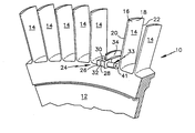
도 1을 참조하면, 일체식 블레이드형 로터(integrally bladed roto : IBR)의 부분은 디스크(12)를 포함하며, 상기 디스크(12)는 이 디스크(12)로부터 반경방향 외측으로 연장되는 다수의 블레이드(14)를 구비한다. 각 블레이드(14)는 디스크(12)에 기계적으로 접착된다. 각 블레이드(14)는 압력 측부(16), 흡입 측부(18), 전연부(20) 및 후연부(22)를 포함한다.Referring to FIG. 1, a portion of an integrally bladed roto (IBR) comprises a
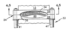
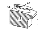
도 2 내지 도 5를 참조하면, 블레이드 수리 다이(24)는 압력 측부 반부(26) 및 흡입 측부 반부(28)와, 상부 표면(30) 및 바닥 표면(32)과, 2개의 반부(26, 28)를 블레이드 스터브(34)에 고정하기 위한 수단(33)을 포함한다. 각 반부(26, 28)는 에어포일 부분(38) 및 플랫폼 트로프(40)를 구비하는 리세스(36)(도 3 내지 도 5 참조)를 포함한다. 에어포일 부분(38)의 기하학적 형상은 각각 로터 블레이드 스터브(34)의 압력 측부(16) 및 흡입 측부(18)와 실질적으로 부합한다. 다이 반부(26, 28) 내의 플랫폼 트로프(40)는 에어포일 부분(38)으로부터 다이 반부(26, 28)까지 상부 표면(30)에서 종단되기 전의 거리로 연장된다. 2개의 다이 반부(26, 28)를 블레이드 스터브(34)에 고정하기 위한 수단(33)은 한쌍의 유압 실린더(41) 또는 다른 기계적 고정 수단(도시하지 않음)을 포함한다.2 to 5, the blade repair die 24 includes a
도 1을 참조하면, 본 발명에서 손상된 또는 결함있는 로터 블레이드(14)를 구비하는 일체식 블레이드형 로터(10)는 이러한 손상된 또는 결함있는 블레이드(14)를 교체용 블레이드(50)(도 7 참조)로 교체함으로써 수리될 수 있다. 제 1 수리 단계는 디스크(12)로부터 연장되는 손상된 블레이드(14)의 일부분, 즉 블레이드 스터브(34)를 잔류시키고 디스크(12)로부터 손상된/결함있는 블레이드(14)를 분리시키는 것이다. 스터브(34)의 필요한 높이는 그 구체적인 적용에 따라 좌우되는데, 즉 수리할 로터 블레이드(14)의 본래 높이, 블레이드 수리 다이(24)의 사이즈, 손상 또는 결함의 성질 등에 의해 좌우된다. 그후에 스터브(34)의 반경방향 외측 표면(42)(도 4 참조)은 디스크(12)에 대한 특정 방향에서 소정의 평탄도 사양으로 기계가공될 수 있다.Referring to FIG. 1, the integrated
취급을 용이하게 하기 위해서, 일체식 블레이드형 로터(10)는 고정구(도시하지 않음)에 부착되어 일체식 블레이드형 로터(10)의 위치가 용이하게 조정될 수 있게 하며, 그에 따라 보다 용이하게 취급할 수 있게 한다. 블레이드 수리 다이(24)는 블레이드 스터브(34)에 부착되며, 다이(24)의 바닥 표면(32)은 일체식 블레이드형 로터의 디스크(12)에 인접하여 위치된다. 블레이드 스터브(34)의 다이(24)의 반경방향 위치는 블레이드 스터브(34)의 특정 부분("x"로 표시됨)이 에어포일 부분(38)위로 연장되도록 위치된다(도 4 참조). 유압 실린더(41)는, 다이(24)가 블레이드 스터브(34)에 대해서 이동되는 것을 방지하기에 충분한 힘을 갖지만 블레이드 스터브(34)를 기계적으로 변형시키지는 않는 힘으로 다이 반부(26, 28)를 블레이드 스터브(34)에 고정한다.In order to facilitate handling, the integral blade-
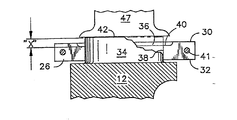
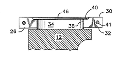
도 4 및 도 5를 참조하면, 에어포일 부분(38)상으로 연장되는 스터브(34)의 부분은 다이 반부(26, 28)의 플랫폼 트로프(40)내로 압출된다. 에어포일 부분(38)상으로 연장되는 좌측으로의 블레이드 스터브(34)의 정확한 정도("x")는, 에어포일 부분(38)상으로 연장되는 스터브(34)의 용적이 비압출된 블레이드 스터브(34)를 둘러싸는 플랫폼 트로프(40)의 실질적인 부분과 동일하게 되도록 선택된다. 플랫폼 트로프에 대해서 상술한 방법으로 에어포일 스터브의 부분("x")의 사이즈를 결정하는 것은 필요한 접착 표면이 형성되게 하는 동시에 접착 동안에 접착 조인트로부터 유동할 수 있는 모든 업셋을 위한 공간을 제공하는 것을 보장한다.4 and 5, the portion of the
제 1 실시예에 있어서, 에어포일 부분(38)상으로 연장되는 블레이드 스터브의 부분("x")은 유압식으로 작동되는 플랫 다이(47)(도 4 참조)를 이용하여 다이 반부(26, 28)의 플랫폼 트로프(40)내로 압출된다. 압출을 용이하게 하기 위해서 블레이드 스터브(34)의 온도를 상승시키는데에는 "펜케이크"형 유도 코일(도시하지 않음) 또는 다른 가열 수단이 이용된다. 바람직한 온도는 블레이드 스터브(34)의 구성 재료에 따라 좌우된다.In the first embodiment, the portion “x” of the blade stub extending over the
제 2 실시예에 있어서, 에어포일 부분(38)상으로 연장되는 블레이드 스터브의 부분("x")은 접착 공정 동안에 플랫폼 트로프(40)내로 압출된다. 블레이드 스터브는 가열되며, 교체용 블레이드는 후술하는 바와 같이 로터 블레이드 스터브에 대해서 가압된다. 블레이드 스터브와 교체용 블레이드 사이의 열 에너지 및 압력은 에어포일상으로 연장되는 블레이드 스터브의 부분("x")이 소성 변형되게 하여 플랫폼 트로프내로 압출되게 한다.In the second embodiment, the portion ("x") of the blade stub extending over the
양 실시예에 있어서, 블레이드 스터브(34)의 외부 기하학적 형상에 실질적으로 부합하는 다이 반부(26, 28)의 에어포일 부분(38)은 블레이드 스터브(34)를 지지하여 변형을 방지한다.In both embodiments, the
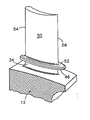
바람직하게, 교체용 블레이드(50)는 블레이드 스터브(34)의 것과 유사한 플랫폼(52)을 포함한다. 교체용 블레이드 플랫폼(52)은 특히 교체용 블레이드(50)의 전연부(54) 및 후연부(56)를 따라서 변형되는 것을 방지하는 확장된 접착 표면을 제공한다. 또한, 교체용 블레이드 플랫폼(52)은 접착력이 가해질 수 있는 표면을 제공한다. 접착전에, 접착할 표면은 탈지, 그리트 분사, 화학세정 및 전기화학적 연마와 같은 기술에 의해 표면상에 형성될 수 있는 부스러기 및 모든 산화물이 제거된다.Preferably, the
전형적으로, 접착은 금속을 유동시키기에 충분한 온도 및 압력의 조건하에서 고진공(10-5mmHg)에서 실행된다. 진공 환경은 접착될 표면상에서의 산화물의 형성을 방지한다. 정확한 접착 압력 및 온도는 접착할 재료에 따라 다양해질 것이다. 그러나, 전형적인 초합금에 있어서는, 온도가 1700℉ 내지 2100℉(930℃ 내지 1150℃)정도 이며, 교체용 블레이드(50) 및 블레이드 스터브(34)를 함께 가압하는 압력은 5ksi 내지 15ksi 정도이다.Typically, the adhesion is carried out at high vacuum (10 -5 mmHg) under conditions of temperature and pressure sufficient to flow the metal. The vacuum environment prevents the formation of oxides on the surface to be bonded. The exact adhesion pressure and temperature will vary depending on the material to be bonded. However, in a typical superalloy, the temperature is on the order of 1700 ° F to 2100 ° F (930 ° C to 1150 ° C), and the pressure to press the
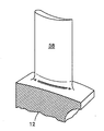
접착후에, 일체식 블레이드형 로터(10)는 고정구(도시하지 않음)로부터 제거되며, 블레이드 수리 다이(24)는 일체식 블레이드형 로터(10)로부터 제거된다. 플랫폼(46, 52)과 접착 동안에 접착 조인트로부터 유동될 수 있는 모든 업셋은 그 후에 종래의 기계가공 기술을 이용하여 기계가공된다. 수리된 블레이드(58)(도 8 참조)는 필요한 블레이드 형상이 될 때까지 기계가공된다. 기계가공후에, 접착된 수리된 블레이드(58)의 부분은 적당한 기계적 특성을 보장하도록 국부적으로 열 처리된다.After bonding, the integral
본 발명은 그 바람직한 실시예를 참조하여 도시하고 설명하였지만, 당 업자들에 의해 본 발명의 정신 및 영역을 벗어남이 없이 본 발명의 다양한 변경이 이뤄질 수 있다. 예를 들면, 다이의 바람직한 실시예는 2개의 반부를 포함하고 있다. 변형 실시예에 있어서, 다이는 2개 부분 이상을 포함할 수 있다. 또한, 설명한 최상의 모드는 블레이드 수리에 있어서의 블레이드 부착의 방법에 대해서 설명했다. 이 방법은 또한 새로운 일체식 블레이드형 로터를 교체하기 위한 목적으로 블레이드를 디스크에 결합하는데도 이용될 수 있다.While the invention has been illustrated and described with reference to its preferred embodiments, various modifications of the invention can be made by those skilled in the art without departing from the spirit and scope of the invention. For example, the preferred embodiment of the die includes two halves. In a variant embodiment, the die may comprise two or more portions. Also, the best mode described described the method of blade attachment in blade repair. This method can also be used to join the blade to the disk for the purpose of replacing a new integrated bladed rotor.
도 1은 일체식 블레이드형 로터 부분의 개략도,1 is a schematic representation of an integral bladed rotor portion,
도 2는 도 1에 도시된 로터 부분상에 설치된 본 발명의 수리 장치의 도면,2 is a view of the repair apparatus of the present invention installed on the rotor portion shown in FIG. 1, FIG.
도 3은 블레이드 스터브의 압출전에 블레이드 수리 다이내에 구비된 일체식 로터 블레이드 스터브의 개략적인 평면도,3 is a schematic plan view of an integrated rotor blade stub provided in the blade repair die prior to extrusion of the blade stub;
도 4는 본 발명의 수리 장치의 한 반부내에 수납된 것으로 도 3에 도시된 일체식 로터 블레이드 스터브의 개략적인 단면도,4 is a schematic cross-sectional view of the integral rotor blade stub shown in FIG. 3, housed in one half of the repair apparatus of the present invention;
도 5는 블레이드 스터브의 일부분이 플랫폼 트로프내로 압출된 것으로 도 4에 도시된 일체식 로터 블레이드 스터브의 도면,FIG. 5 is a view of the integral rotor blade stub shown in FIG. 4 with a portion of the blade stub extruded into the platform trough; FIG.
도 6은 플랫폼을 구비한 일체식 로터 블레이드 스터브의 개략적인 사시도,6 is a schematic perspective view of an integrated rotor blade stub with a platform;
도 7은 일체식 로터 블레이드 스터브의 플랫폼에 접착된 교체 블레이드의 개략적인 사시도,7 is a schematic perspective view of a replacement blade bonded to a platform of an integrated rotor blade stub;
도 8은 플랫폼의 과잉 재료가 제거된 후의 상태를 도시하는 것으로 도 7에 도시된 일체식 로터 블레이드를 도시한 도면.FIG. 8 shows the integrated rotor blade shown in FIG. 7 showing the state after excess material of the platform has been removed. FIG.
도면의 주요부분에 대한 부호의 설명Explanation of symbols for main parts of the drawings
10 : 일체식 블레이드형 로터 12 : 디스크10 integral
14 : 블레이드 16 : 압력 측부14
18 : 흡입 측부 24 : 블레이드 수리 다이18: suction side 24: blade repair die
26, 28 : 반부 34 : 블레이드 스터브26, 28: half 34: blade stub
40 : 플랫폼 트로프 46, 52 : 플랫폼40:
58 : 수리된 블레이드58: repaired blade
Claims (25)
Applications Claiming Priority (3)
| Application Number | Priority Date | Filing Date | Title |
|---|---|---|---|
| US08/748,172 | 1996-11-12 | ||
| US8/748,172 | 1996-11-12 | ||
| US08/748,172 US5755031A (en) | 1996-11-12 | 1996-11-12 | Method for attaching a rotor blade to an integrally bladed rotor |
Publications (2)
| Publication Number | Publication Date |
|---|---|
| KR19980042275A KR19980042275A (en) | 1998-08-17 |
| KR100456765B1 true KR100456765B1 (en) | 2005-02-28 |
Family
ID=25008331
Family Applications (1)
| Application Number | Title | Priority Date | Filing Date |
|---|---|---|---|
| KR1019970059204A KR100456765B1 (en) | 1996-11-12 | 1997-11-11 | Method for attaching a rotor blade to an integrally bladed rotor |
Country Status (5)
| Country | Link |
|---|---|
| US (1) | US5755031A (en) |
| EP (1) | EP0841470B1 (en) |
| JP (1) | JPH10153101A (en) |
| KR (1) | KR100456765B1 (en) |
| DE (1) | DE69722559T2 (en) |
Families Citing this family (32)
| Publication number | Priority date | Publication date | Assignee | Title |
|---|---|---|---|---|
| DE19642980C1 (en) * | 1996-10-18 | 1998-08-13 | Mtu Muenchen Gmbh | Procedure for repairing worn blade tips of compressor and turbine blades |
| US6128820A (en) * | 1998-10-20 | 2000-10-10 | General Electric Co. | Method of repairing damaged turbine rotor wheels using differentially controlled temperatures |
| US6244495B1 (en) * | 1998-11-06 | 2001-06-12 | United Technologies Corporation | Gripper |
| US6129257A (en) * | 1999-12-01 | 2000-10-10 | Allison Engine Company, Inc. | High temperature brazing fixture |
| US6478545B2 (en) * | 2001-03-07 | 2002-11-12 | General Electric Company | Fluted blisk |
| US6536110B2 (en) * | 2001-04-17 | 2003-03-25 | United Technologies Corporation | Integrally bladed rotor airfoil fabrication and repair techniques |
| KR100999849B1 (en) * | 2003-07-14 | 2010-12-13 | 두산중공업 주식회사 | method for change blade of turbine rotor |
| DE10343760B4 (en) * | 2003-09-22 | 2008-02-14 | Mtu Aero Engines Gmbh | Method for producing or repairing a bladed rotor for a turbomachine, as well as blades or spare blade sections suitable therefor |
| US8516674B2 (en) * | 2003-11-14 | 2013-08-27 | General Electric Company | Solid state resistance welding for airfoil repair and manufacture |
| GB0412775D0 (en) * | 2004-06-09 | 2004-07-07 | Rolls Royce Plc | Method of replacing damaged aerofoil |
| DE102004032461A1 (en) * | 2004-06-30 | 2006-02-02 | Rolls-Royce Deutschland Ltd & Co Kg | Process and repair blade part for BLISK repair or BLISKs new production |
| US7448844B1 (en) | 2005-08-16 | 2008-11-11 | Florida Turbine Technologies, Inc. | Blisk having partially cut blade attachment |
| CN100361776C (en) * | 2005-12-19 | 2008-01-16 | 西北工业大学 | Repairing method of solid impeller disc |
| US7841834B1 (en) | 2006-01-27 | 2010-11-30 | Florida Turbine Technologies, Inc. | Method and leading edge replacement insert for repairing a turbine engine blade |
| DE102006008836A1 (en) * | 2006-02-25 | 2007-09-06 | Mtu Aero Engines Gmbh | Method for producing and / or repairing an integrally bladed rotor |
| US20090119919A1 (en) * | 2007-11-12 | 2009-05-14 | Honeywell International, Inc. | Components for gas turbine engines and methods for manufacturing components for gas turbine engines |
| DE102007062559A1 (en) * | 2007-12-22 | 2009-06-25 | Mtu Aero Engines Gmbh | Method for producing and repairing a component and component of a gas turbine |
| US20090214335A1 (en) * | 2008-02-21 | 2009-08-27 | Long Merrell W | Method of repair for cantilevered stators |
| US8479391B2 (en) * | 2009-12-16 | 2013-07-09 | United Technologies Corporation | Consumable collar for linear friction welding of blade replacement for damaged integrally bladed rotors |
| US8613138B2 (en) | 2009-12-16 | 2013-12-24 | United Technologies Corporation | Repair of integrally bladed rotors |
| US9694440B2 (en) * | 2010-10-22 | 2017-07-04 | United Technologies Corporation | Support collar geometry for linear friction welding |
| US8601689B2 (en) * | 2011-06-17 | 2013-12-10 | General Electric Company | Method and apparatus to repair a turbomachine rotor wheel |
| GB2519532B (en) | 2013-10-23 | 2016-06-29 | Rolls Royce Plc | Method and Apparatus for Supporting Blades |
| US9724780B2 (en) | 2014-06-05 | 2017-08-08 | Honeywell International Inc. | Dual alloy turbine rotors and methods for manufacturing the same |
| US10060282B2 (en) * | 2014-06-10 | 2018-08-28 | United Technologies Corporation | Geared turbofan with integrally bladed rotor |
| EP2998060B1 (en) * | 2014-09-16 | 2019-01-02 | Rolls-Royce plc | Method of replacing damaged blade |
| CN105057969B (en) * | 2015-05-29 | 2017-12-08 | 西安交通大学 | Repairing method of solid impeller disc based on MICROBEAM PLASMA WELDING and electric spark finishing |
| GB201707103D0 (en) | 2017-05-04 | 2017-06-21 | Rolls Royce Plc | Vane arrangement for a gas turbine engine |
| GB201707101D0 (en) | 2017-05-04 | 2017-06-21 | Rolls Royce Plc | Vane arrangement for a gas turbine engine |
| JP7261697B2 (en) * | 2018-09-06 | 2023-04-20 | エトスエナジー・イタリア・ソシエタ・ペル・アチオニ | Method for repairing the rotor of a multi-stage axial compressor of a gas turbine |
| CN109396764A (en) * | 2018-11-17 | 2019-03-01 | 共享智能装备有限公司 | A kind of processing method of mixed-flow block cast runner |
| US20230392503A1 (en) * | 2022-06-02 | 2023-12-07 | Pratt & Whitney Canada Corp. | Airfoil ribs for rotor blades |
Family Cites Families (9)
| Publication number | Priority date | Publication date | Assignee | Title |
|---|---|---|---|---|
| US3574924A (en) * | 1968-10-28 | 1971-04-13 | North American Rockwell | Solid state repair method and means |
| US3758347A (en) * | 1970-12-21 | 1973-09-11 | Gen Electric | Method for improving a metal casting |
| US4063939A (en) * | 1975-06-27 | 1977-12-20 | Special Metals Corporation | Composite turbine wheel and process for making same |
| US4864706A (en) * | 1987-08-12 | 1989-09-12 | United Technologies Corporation | Fabrication of dual alloy integrally bladed rotors |
| US4784573A (en) * | 1987-08-17 | 1988-11-15 | United Technologies Corporation | Turbine blade attachment |
| US4883216A (en) * | 1988-03-28 | 1989-11-28 | General Electric Company | Method for bonding an article projection |
| US4873751A (en) * | 1988-12-27 | 1989-10-17 | United Technologies Corporation | Fabrication or repair technique for integrally bladed rotor assembly |
| US5100050A (en) * | 1989-10-04 | 1992-03-31 | General Electric Company | Method of manufacturing dual alloy turbine disks |
| FR2716397B1 (en) * | 1994-02-23 | 1996-04-05 | Snecma | Method of welding two parts of the blade. |
-
1996
- 1996-11-12 US US08/748,172 patent/US5755031A/en not_active Expired - Lifetime
-
1997
- 1997-11-07 EP EP97308939A patent/EP0841470B1/en not_active Expired - Lifetime
- 1997-11-07 DE DE69722559T patent/DE69722559T2/en not_active Expired - Lifetime
- 1997-11-11 KR KR1019970059204A patent/KR100456765B1/en not_active IP Right Cessation
- 1997-11-11 JP JP9323959A patent/JPH10153101A/en active Pending
Also Published As
| Publication number | Publication date |
|---|---|
| US5755031A (en) | 1998-05-26 |
| DE69722559D1 (en) | 2003-07-10 |
| EP0841470A3 (en) | 2000-03-08 |
| DE69722559T2 (en) | 2004-04-22 |
| EP0841470A2 (en) | 1998-05-13 |
| KR19980042275A (en) | 1998-08-17 |
| JPH10153101A (en) | 1998-06-09 |
| EP0841470B1 (en) | 2003-06-04 |
Similar Documents
| Publication | Publication Date | Title |
|---|---|---|
| KR100456765B1 (en) | Method for attaching a rotor blade to an integrally bladed rotor | |
| US6106233A (en) | Method for linear friction welding and product made by such method | |
| CN1027388C (en) | Fabrication or repair technique for integrally bladed rotor assembly | |
| US8006380B2 (en) | Method of replacing damaged aerofoil | |
| KR100672134B1 (en) | Turbine nozzle segment and method of repairing same | |
| US5865364A (en) | Process for linear friction welding | |
| US6494677B1 (en) | Turbine nozzle segment and method of repairing same | |
| US9186757B2 (en) | Method of providing a turbine blade tip repair | |
| CA2823525C (en) | Method for producing a metal reinforcement | |
| CA2529337C (en) | Turbine nozzle segment and method of repairing same | |
| EP1239116A2 (en) | Fluted blisk | |
| US20070079507A1 (en) | Blade shroud repair | |
| EP0753376B1 (en) | Method of repairing an abradable seal | |
| FR2739045A1 (en) | METHOD FOR MANUFACTURING A TURBOMACHINE HOLLOW DANE | |
| JP2001317490A (en) | Welding repair of blisk | |
| CN1295900A (en) | Turbine inlet guiding section and repairing method thereof | |
| EP1564371A2 (en) | Method of repair for cast article | |
| JP2003161111A (en) | Method for repairing vane | |
| US8661669B2 (en) | Method of making and joining an aerofoil and root | |
| EP2239083A1 (en) | Internally supported airfoil and method for internally supporting a hollow airfoil during manufacturing. | |
| CA2108671A1 (en) | Bladed disc assembly by hip diffusion bonding | |
| US5503532A (en) | Diffusion bonded airfoil and method | |
| JPH10317906A (en) | Method for replacing rotor blade of rotor with integral blade | |
| US20110299982A1 (en) | Method for repairing a guide blade segment for a jet engine | |
| JPS61215402A (en) | Regenerating process for tenon |
Legal Events
| Date | Code | Title | Description |
|---|---|---|---|
| A201 | Request for examination | ||
| E701 | Decision to grant or registration of patent right | ||
| GRNT | Written decision to grant | ||
| LAPS | Lapse due to unpaid annual fee |