KR100443648B1 - Manhole Lining Material and Manhole Lining Method - Google Patents
Manhole Lining Material and Manhole Lining Method Download PDFInfo
- Publication number
- KR100443648B1 KR100443648B1 KR1019970007185A KR19970007185A KR100443648B1 KR 100443648 B1 KR100443648 B1 KR 100443648B1 KR 1019970007185 A KR1019970007185 A KR 1019970007185A KR 19970007185 A KR19970007185 A KR 19970007185A KR 100443648 B1 KR100443648 B1 KR 100443648B1
- Authority
- KR
- South Korea
- Prior art keywords
- manhole
- lining material
- resin
- lining
- attached
- Prior art date
Links
- 239000000463 material Substances 0.000 title claims abstract description 237
- 238000000034 method Methods 0.000 title claims abstract description 34
- 229920005989 resin Polymers 0.000 claims abstract description 131
- 239000011347 resin Substances 0.000 claims abstract description 131
- 230000002745 absorbent Effects 0.000 claims abstract description 65
- 239000002250 absorbent Substances 0.000 claims abstract description 65
- 239000002985 plastic film Substances 0.000 claims abstract description 19
- 229920006255 plastic film Polymers 0.000 claims abstract description 19
- XLYOFNOQVPJJNP-UHFFFAOYSA-N water Substances O XLYOFNOQVPJJNP-UHFFFAOYSA-N 0.000 claims description 59
- 239000000945 filler Substances 0.000 claims description 37
- 229920001187 thermosetting polymer Polymers 0.000 claims description 24
- 230000002093 peripheral effect Effects 0.000 claims description 15
- 238000002347 injection Methods 0.000 claims description 10
- 239000007924 injection Substances 0.000 claims description 10
- 239000012530 fluid Substances 0.000 claims description 9
- 239000011521 glass Substances 0.000 claims description 9
- 239000004744 fabric Substances 0.000 claims description 7
- 235000007164 Oryza sativa Nutrition 0.000 claims description 6
- 235000009566 rice Nutrition 0.000 claims description 6
- 238000003825 pressing Methods 0.000 claims description 4
- 239000011358 absorbing material Substances 0.000 claims description 2
- 240000007594 Oryza sativa Species 0.000 claims 1
- 230000032683 aging Effects 0.000 abstract description 8
- 238000004519 manufacturing process Methods 0.000 description 15
- 239000004745 nonwoven fabric Substances 0.000 description 10
- 238000010438 heat treatment Methods 0.000 description 8
- 239000010865 sewage Substances 0.000 description 8
- 239000002184 metal Substances 0.000 description 7
- 238000011144 upstream manufacturing Methods 0.000 description 7
- 230000036448 vitalisation Effects 0.000 description 6
- 241000209094 Oryza Species 0.000 description 5
- 229920001971 elastomer Polymers 0.000 description 4
- 238000003780 insertion Methods 0.000 description 4
- 230000037431 insertion Effects 0.000 description 4
- 238000012805 post-processing Methods 0.000 description 4
- 229910001220 stainless steel Inorganic materials 0.000 description 4
- 239000010935 stainless steel Substances 0.000 description 4
- 239000006096 absorbing agent Substances 0.000 description 3
- 238000010276 construction Methods 0.000 description 3
- 238000001723 curing Methods 0.000 description 3
- 238000010586 diagram Methods 0.000 description 3
- 239000003822 epoxy resin Substances 0.000 description 3
- 229920000647 polyepoxide Polymers 0.000 description 3
- -1 polypropylene Polymers 0.000 description 3
- 238000012545 processing Methods 0.000 description 3
- 239000002956 ash Substances 0.000 description 2
- 239000005457 ice water Substances 0.000 description 2
- 239000004570 mortar (masonry) Substances 0.000 description 2
- 229920000728 polyester Polymers 0.000 description 2
- JOYRKODLDBILNP-UHFFFAOYSA-N Ethyl urethane Chemical compound CCOC(N)=O JOYRKODLDBILNP-UHFFFAOYSA-N 0.000 description 1
- 235000002918 Fraxinus excelsior Nutrition 0.000 description 1
- 239000004677 Nylon Substances 0.000 description 1
- 239000004698 Polyethylene Substances 0.000 description 1
- 239000004743 Polypropylene Substances 0.000 description 1
- 239000004568 cement Substances 0.000 description 1
- 238000004891 communication Methods 0.000 description 1
- 238000005520 cutting process Methods 0.000 description 1
- 238000005553 drilling Methods 0.000 description 1
- 230000000694 effects Effects 0.000 description 1
- 229920006241 epoxy vinyl ester resin Polymers 0.000 description 1
- 238000013007 heat curing Methods 0.000 description 1
- 239000010903 husk Substances 0.000 description 1
- 239000007788 liquid Substances 0.000 description 1
- 239000000203 mixture Substances 0.000 description 1
- 229920001778 nylon Polymers 0.000 description 1
- 239000004033 plastic Substances 0.000 description 1
- 229920003023 plastic Polymers 0.000 description 1
- 229920001225 polyester resin Polymers 0.000 description 1
- 239000004645 polyester resin Substances 0.000 description 1
- 229920000573 polyethylene Polymers 0.000 description 1
- 229920001155 polypropylene Polymers 0.000 description 1
- 229920002635 polyurethane Polymers 0.000 description 1
- 239000004814 polyurethane Substances 0.000 description 1
- 230000003014 reinforcing effect Effects 0.000 description 1
- 230000008439 repair process Effects 0.000 description 1
- 230000000452 restraining effect Effects 0.000 description 1
- 230000000087 stabilizing effect Effects 0.000 description 1
- 229920001567 vinyl ester resin Polymers 0.000 description 1
Images


Classifications
-
- E—FIXED CONSTRUCTIONS
- E03—WATER SUPPLY; SEWERAGE
- E03F—SEWERS; CESSPOOLS
- E03F5/00—Sewerage structures
- E03F5/02—Manhole shafts or other inspection chambers; Snow-filling openings; accessories
- E03F5/025—Manhole shafts or other inspection chambers; Snow-filling openings; accessories provided with a liner
-
- B—PERFORMING OPERATIONS; TRANSPORTING
- B29—WORKING OF PLASTICS; WORKING OF SUBSTANCES IN A PLASTIC STATE IN GENERAL
- B29C—SHAPING OR JOINING OF PLASTICS; SHAPING OF MATERIAL IN A PLASTIC STATE, NOT OTHERWISE PROVIDED FOR; AFTER-TREATMENT OF THE SHAPED PRODUCTS, e.g. REPAIRING
- B29C63/00—Lining or sheathing, i.e. applying preformed layers or sheathings of plastics; Apparatus therefor
- B29C63/26—Lining or sheathing of internal surfaces
- B29C63/34—Lining or sheathing of internal surfaces using tubular layers or sheathings
-
- E—FIXED CONSTRUCTIONS
- E02—HYDRAULIC ENGINEERING; FOUNDATIONS; SOIL SHIFTING
- E02D—FOUNDATIONS; EXCAVATIONS; EMBANKMENTS; UNDERGROUND OR UNDERWATER STRUCTURES
- E02D29/00—Independent underground or underwater structures; Retaining walls
- E02D29/12—Manhole shafts; Other inspection or access chambers; Accessories therefor
- E02D29/125—Manhole shafts; Other inspection or access chambers; Accessories therefor characterised by the lining of the shaft
-
- E—FIXED CONSTRUCTIONS
- E02—HYDRAULIC ENGINEERING; FOUNDATIONS; SOIL SHIFTING
- E02D—FOUNDATIONS; EXCAVATIONS; EMBANKMENTS; UNDERGROUND OR UNDERWATER STRUCTURES
- E02D29/00—Independent underground or underwater structures; Retaining walls
- E02D29/12—Manhole shafts; Other inspection or access chambers; Accessories therefor
- E02D29/14—Covers for manholes or the like; Frames for covers
- E02D29/1472—Cover entirely made of synthetic material
-
- E—FIXED CONSTRUCTIONS
- E03—WATER SUPPLY; SEWERAGE
- E03F—SEWERS; CESSPOOLS
- E03F5/00—Sewerage structures
- E03F5/02—Manhole shafts or other inspection chambers; Snow-filling openings; accessories
-
- E—FIXED CONSTRUCTIONS
- E03—WATER SUPPLY; SEWERAGE
- E03F—SEWERS; CESSPOOLS
- E03F7/00—Other installations or implements for operating sewer systems, e.g. for preventing or indicating stoppage; Emptying cesspools
- E03F7/02—Shut-off devices
-
- F—MECHANICAL ENGINEERING; LIGHTING; HEATING; WEAPONS; BLASTING
- F16—ENGINEERING ELEMENTS AND UNITS; GENERAL MEASURES FOR PRODUCING AND MAINTAINING EFFECTIVE FUNCTIONING OF MACHINES OR INSTALLATIONS; THERMAL INSULATION IN GENERAL
- F16L—PIPES; JOINTS OR FITTINGS FOR PIPES; SUPPORTS FOR PIPES, CABLES OR PROTECTIVE TUBING; MEANS FOR THERMAL INSULATION IN GENERAL
- F16L55/00—Devices or appurtenances for use in, or in connection with, pipes or pipe systems
- F16L55/16—Devices for covering leaks in pipes or hoses, e.g. hose-menders
- F16L55/162—Devices for covering leaks in pipes or hoses, e.g. hose-menders from inside the pipe
- F16L55/165—Devices for covering leaks in pipes or hoses, e.g. hose-menders from inside the pipe a pipe or flexible liner being inserted in the damaged section
- F16L55/1651—Devices for covering leaks in pipes or hoses, e.g. hose-menders from inside the pipe a pipe or flexible liner being inserted in the damaged section the flexible liner being everted
Landscapes
- Engineering & Computer Science (AREA)
- Life Sciences & Earth Sciences (AREA)
- General Engineering & Computer Science (AREA)
- Paleontology (AREA)
- General Life Sciences & Earth Sciences (AREA)
- Water Supply & Treatment (AREA)
- Structural Engineering (AREA)
- Hydrology & Water Resources (AREA)
- Civil Engineering (AREA)
- Environmental & Geological Engineering (AREA)
- Public Health (AREA)
- Mining & Mineral Resources (AREA)
- Health & Medical Sciences (AREA)
- Manufacturing & Machinery (AREA)
- Mechanical Engineering (AREA)
- Lining Or Joining Of Plastics Or The Like (AREA)
- Underground Structures, Protecting, Testing And Restoring Foundations (AREA)
- Sewage (AREA)
Abstract
맨홀의 벽의 노후화가 심한 경우라도, 맨홀의 라이닝 후에 스텝을 충분한 강도로 강고하게 부착할 수 있는 맨홀용 라이닝재 및 맨홀라이닝공법을 제공하는 것이다.Even if the aging of the wall of the manhole is severe, it is to provide a manhole lining material and a manhole lining method that can firmly attach the step with sufficient strength after lining the manhole.
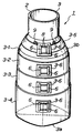
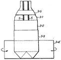
경화성 수지를 함침하고, 외주면이 기밀성이 높은 플라스틱필름으로 피복된 수지흡수재(3)에 복수의 스텝부착 베이스(6)가, 이것에 설치된 볼트(7)가 내주면으로 돌출하는 형상으로, 깊이방향으로 적당한 간격으로 부착되어 맨홀용 라이닝재(1)를 구성한다.A plurality of stepped bases 6 protrude to the inner circumferential surface of the resin absorbent material 3 impregnated with the curable resin and the outer circumferential surface of which is covered with a highly airtight plastic film, and protrude toward the inner circumferential surface thereof. It is attached at appropriate intervals and constitutes the manhole lining material 1.
본 발명에 의하면, 스텝(47)은 종래와 같이 맨홀(21)의 벽이 아니라, 스텝부착베이스(6)를 통하여 부착되기 때문에, 맨홀(21)의 벽의 노후화가 심한 경우라도, 스텝(47)을 충분한 강조로 강고하게 부착할 수 있고, 그 스텝(47)에 작용하는 하중(작업자의 체중)을 라이닝재(1) 전체로 충분히 받을 수 있다.According to the present invention, since the step 47 is attached through the step attachment base 6 instead of the wall of the manhole 21 as in the prior art, even if the aging of the wall of the manhole 21 is severe, the step 47 ) Can be firmly attached with sufficient emphasis, and the load (worker's weight) acting on the step 47 can be sufficiently received by the entire lining material 1.
Description
본 발명은, 경화성 수지를 함침한 맨홀용 라이닝재와, 그 맨홀용 라이닝재를 사용하여 시공되는 맨홀라이닝공법에 관한 것이다.The present invention relates to a manhole lining material impregnated with a curable resin and a manhole lining method constructed by using the manhole lining material.
땅속에 매설된 하수관 등의 관로가 노후화한 경우, 그 관로를 파내는 일없이, 그 내주면에 라이닝을 시공하여 해당하는 관로를 보수하는 관라이닝공법이 알려져 있다.When pipelines such as sewer pipes buried in the ground become obsolete, a pipe lining method is known that repairs the pipeline by lining the inner circumferential surface without digging out the pipeline.
상기 관라이닝공법은, 외표면이 기밀성이 높은 플라스틱필름 등의 외표면재로 피복된 관형상 수지흡수재에 경화성 수지를 함침시켜서 이루어진 관라이닝재를유체압력에 의하여 관로 내로 반전삽입함과 아울러, 이것을 관로 내주면으로 압압하고, 그 상태를 유지한 채로, 관라이닝재에 함침된 경화성 수지를 경화시킴으로써, 관로의 내주면에 라이닝을 시행하여 그 관로를 보수하는 공법이다.The pipe lining method inverts and inserts a tube lining material formed by impregnating a curable resin into a tubular resin absorbent material whose outer surface is coated with an outer surface material such as a plastic film having high airtightness into the pipeline by fluid pressure. It is a method of repairing the conduit by lining the inner circumferential surface of the conduit by pressing the inner circumferential surface and curing the curable resin impregnated in the tube lining material while maintaining the state.
그런데, 상기 공법을 맨홀의 라이닝에 그대로 적용하는 것이 고려된다.By the way, it is considered to apply the above method to the lining of the manhole as it is.
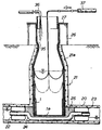
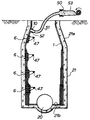
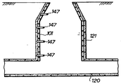
즉, 도 33에 표시하는 바와 같이, 먼저, 하수관 등의 관로(120)의 맨홀(121)보다도 상류측을 지수플러그(122)로 흐름을 막고, 맨홀용 라이닝재(101)를 예컨대 유체압력에 의하여 맨홀(121) 속으로 지상측으로부터 반전삽입한 후, 그 라이닝재(101)를 맨홀(121)의 내벽에 압압한 채로, 라이닝재(101)에 함침된 경화성 수지를 경화시키면, 맨홀(121)의 내주벽이 라이닝재(101)에 의하여 라이닝된다. 그리고, 라이닝작업이 종료할 때까지의 사이, 관로(120) 내를 흐르는 하수 등은 지수플러그(122)의 상류측에 설치된 펌프(140)에 의해 퍼올려져서 다른 장소로 흐르게 된다.That is, as shown in FIG. 33, first, the upstream side of the
그런데, 상기 바와 같이, 맨홀(121)을 라이닝재(101)를 사용하여 라이닝하기 전에, 맨홀(121)의 벽에 깊이방향으로 부착되어 있던 복수의 승강용 스텝(도면에 표시하지 않음)을 제거하고, 맨홀(121)이 라이닝재(101)에 의하여 라이닝되면, 경화한 라이닝재(101)의 내면측으로부터 라이닝재(101)와 맨홀(121)의 벽에 구멍을 뚫어서 도 34에 표시하는 바와 같이, 새로운 복수의 스텝(147)을 라이닝재(101)를 통하여 맨홀(121)의 벽에 박음으로써 이것을 깊이방향으로 적당한 간격으로 부착하였다.By the way, as mentioned above, before lining the
또, 맨홀(121) 내에서 라이닝재(101)가 경화한 후에 그 라이닝재(101)가 열수축하여, 맨홀(121)과 라이닝재(101)의 사이에 틈새가 발생하기 때문에, 라이닝재(101)에 구멍(충전구)을 뚫고, 그 구멍으로부터 충전재를 맨홀(121)과 라이닝재(101)의 틈새에 충전하는 일이 행하여지고 있었다.Moreover, since the
그러나, 맨홀(121)의 벽의 노후화가 심한 경우에는, 스텝(147)을 벽에 박아넣어서 이것을 부착하여도, 충분한 부착강도가 얻어지지 않는다는 문제가 있었다.However, when the aging of the wall of the
또, 스텝부착용 구멍이나 충전구를 형성하기 위한 구멍뚫기작업은, 전적으로 드릴에 의한 인력작업이었기 때문에, 막대한 노력을 필요하다는 문제가 있었다.Moreover, since the perforation work for forming a stepping hole and a filling hole was a manpower work by a drill entirely, there existed a problem that enormous effort is required.
본 발명은 상기 문제를 감안하여 이루어진 것으로, 그 목적으로 하는 바는 맨홀의 벽의 노후화가 심한 경우에도, 맨홀의 라이닝 후에 스텝을 충분한 강도로 강고하게 부착할 수 있는 맨홀용 라이닝재 및 맨홀용 라이닝공법을 제공하는데 있다.The present invention has been made in view of the above problems, and its object is to provide a manhole lining material and a manhole lining that can firmly attach a step to a sufficient strength after lining of the manhole even when the wall of the manhole is severely aged. To provide a process.
또, 본 발명의 목적은, 충전구를 간단하게 형성할 수 있는 맨홀용 라이닝재 및 맨홀라이닝공법을 제공하는데 있다.Moreover, the objective of this invention is providing the manhole lining material and the manhole lining method which can form a filling hole easily.
도 1은, 본 발명의 실시예 1에 관한 맨홀용 라이닝재의 사시도이다.1 is a perspective view of a manhole lining material according to a first embodiment of the present invention.
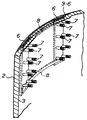
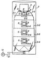
도 2는, 본 발명의 실시예 1에 관한 맨홀용 라이닝재의 스텝부착 베이스부를 내주측에서 본 부분사시도이다.It is a partial perspective view which looked at the base part with a step of the manhole lining material which concerns on Example 1 of this invention from the inner peripheral side.
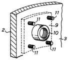
도 3은, 본 발명의 실시예 1에 관한 맨홀용 라이닝재의 충전구가 형성된 베이스부를 내주측에서 본 부분사이도이다.Fig. 3 is a view between the portions of the base formed with the filling port of the manhole lining material according to the first embodiment of the present invention as viewed from the inner circumferential side.
도 4는, 본 발명의 실시예 1에 관한 맨홀용 라이닝재의 제조방법을 표시하는 설명도이다.4 is an explanatory diagram showing a method for manufacturing a manhole lining material according to Example 1 of the present invention.
도 5는, 본 발명의 실시예 1에 관한 맨홀용 라이닝재의 제조방법을 표시하는 설명도이다.FIG. 5: is explanatory drawing which shows the manufacturing method of the manhole lining material which concerns on Example 1 of this invention.
도 6은, 본 발명의 실시예 1에 관한 맨홀용 라이닝재의 제조방법을 표시하는 설명도이다.FIG. 6: is explanatory drawing which shows the manufacturing method of the manhole lining material which concerns on Example 1 of this invention.
도 7은, 본 발명의 실시예 1에 관한 맨홀용 라이닝재의 제조방법을 표시하는 설명도이다.FIG. 7: is explanatory drawing which shows the manufacturing method of the manhole lining material which concerns on Example 1 of this invention.
도 8은, 본 발명의 실시예 1에 관한 맨홀용 라이닝재의 제조방법을 표시하는 설명도이다.8 is an explanatory diagram showing a method for manufacturing a manhole lining material according to Example 1 of the present invention.
도 9는, 본 발명의 실시예 1에 관한 맨홀용 라이닝재의 제조방법을 표시하는설명도이다.9 is an explanatory diagram showing a method for manufacturing a manhole lining material according to Example 1 of the present invention.
도 10은, 본 발명의 실시예 1에 관한 맨홀용 라이닝재의 제조방법을 표시하는 설명도이다.FIG. 10: is explanatory drawing which shows the manufacturing method of the manhole lining material which concerns on Example 1 of this invention.
도 11은, 본 발명의 실시예 1에 관한 맨홀용 라이닝재의 제조방법을 표시하는 설명도이다.FIG. 11: is explanatory drawing which shows the manufacturing method of the manhole lining material which concerns on Example 1 of this invention.
도 12는, 본 발명의 실시예 1에 관한 맨홀용 라이닝재의 제조방법을 표시하는 설명도이다.It is explanatory drawing which shows the manufacturing method of the manhole lining material which concerns on Example 1 of this invention.
도 13은, 본 발명의 실시예 1에 관한 맨홀용 라이닝재의 제조방법을 표시하는 설명도이다.It is explanatory drawing which shows the manufacturing method of the manhole lining material which concerns on Example 1 of this invention.
도 14는, 본 발명의 실시예 1에 관한 맨홀용 라이닝재의 제조방법을 표시하는 설명도이다.It is explanatory drawing which shows the manufacturing method of the manhole lining material which concerns on Example 1 of this invention.
도 15는, 본 발명의 실시예 1에 관한 맨홀라이닝공법을 표시하는 단면도이다.Fig. 15 is a sectional view showing the manhole lining method according to the first embodiment of the present invention.
도 16은, 본 발명의 실시예 1에 관한 맨홀라이닝공법을 표시하는 단면도이다.16 is a cross-sectional view showing a manhole lining method according to the first embodiment of the present invention.
도 17은, 본 발명의 실시예 1에 관한 맨홀라이닝공법을 표시하는 단면도이다.17 is a cross-sectional view showing a manhole lining method according to the first embodiment of the present invention.
도 18은, 본 발명의 실시예 1에 관한 맨홀라이닝공법을 표시하는 단면도이다.18 is a cross-sectional view showing a manhole lining method according to the first embodiment of the present invention.
도 19는, 본 발명의 실시예 1에 관한 맨홀라이닝공법을 표시하는 단면도이다.19 is a cross-sectional view showing a manhole lining method according to the first embodiment of the present invention.
도 20은, 본 발명의 실시예 1에 있어서의 라이닝 중의 스텝부착 베이스의 상태를 표시하는 단면도이다.It is sectional drawing which shows the state of the stepped base during lining in Example 1 of this invention.
도 21은, 본 발명의 실시예 1에 있어서의 라이닝 중의 충전구가 형성된 베이스의 상태를 표시하는 단면도이다.It is sectional drawing which shows the state of the base in which the filling opening in the lining in Example 1 of this invention was formed.
도 22는, 도 21의 화살표가 가리키는 X방향의 도면이다.22 is a view in the X direction indicated by an arrow in FIG. 21.
도 23은, 본 발명의 실시예 1에 있어서의 라이닝 후의 스텝부착 베이스의 상태를 표시하는 단면도이다.It is sectional drawing which shows the state of the stepped base after lining in Example 1 of this invention.
도 24는, 본 발명의 실시예 1에 있어서의 스텝부착상태를 표시하는 단면도이다.24 is a cross-sectional view showing a step attachment state in the first embodiment of the present invention.
도 25는, 본 발명의 실시예 1에 있어서의 스텝부착상태를 표시하는 부분 사시도이다.Fig. 25 is a partial perspective view showing the step attachment state in the first embodiment of the present invention.
도 26은, 본 발명의 실시예 1에 있어서의 충전재의 주입상태를 표시하는 단면도이다.Fig. 26 is a sectional view showing an injection state of a filler in Example 1 of the present invention.
도 27은, 본 발명의 실시예 2에 있어서의 라이닝 중의 스텝부착 베이스의 상태를 표시하는 단면도이다.It is sectional drawing which shows the state of the base with a step in the lining in Example 2 of this invention.
도 28은, 본 발명의 실시예 2에 있어서의 스텝의 부착상태를 표시하는 단면도이다.Fig. 28 is a cross-sectional view showing the attachment state of the step in the second embodiment of the present invention.
도 29는, 본 발명의 실시예 3에 관한 맨홀용 라이닝재를 내주면측으로부터 본 부분 정면도이다.It is a partial front view which looked at the lining material for manholes which concerns on Example 3 of this invention from the inner peripheral surface side.
도 30은, 본 발명의 실시예 3에 있어서의 라이닝 중의 스텝부착 베이스의 상태를 표시하는 단면도이다.It is sectional drawing which shows the state of the base with a step in the lining in Example 3 of this invention.
도 31은, 본 발명의 실시예 3에 있어서의 스텝의 부착상태를 표시하는 사시도이다.Fig. 31 is a perspective view showing the attachment state of the step in the third embodiment of the present invention.
도 32는, 본 발명의 실시예 3에 있어서의 스텝의 바(bar) 부착부의 구조를 표시하는 부분 파단면도이다.Fig. 32 is a partial sectional sectional view showing the structure of the bar attachment part of the step in the third embodiment of the present invention.
도 33은, 종래의 맨홀라이닝공법을 표시하는 단면도이다.33 is a cross-sectional view showing a conventional manhole lining method.
도 34는, 종래의 맨홀라이닝공법을 표시하는 단면도이다.34 is a cross-sectional view showing a conventional manhole lining method.
-도면의 주요부분에 대한 부호의 설명-Explanation of symbols on the main parts of the drawing
(1) ---------------------- 맨홀용 라이닝재,(1) ---------------------- Manhole lining material,
(2) ---------------------- 플라스틱필름,(2) ---------------------- plastic film,
(3) ---------------------- 수지흡수재,(3) ---------------------- resin absorber,
(4) ---------------------- 열경화성 수지,(4) ---------------------- thermosetting resin,
(5) ---------------------- 유리직물,(5) ---------------------- glass fabric,
(6) ---------------------- 스텝부착 베이스,(6) ---------------------- Stepped Base,
(7) ---------------------- 볼트,(7) ---------------------- bolts,
(9) ---------------------- 충전구가 형성된 베이스,(9) ---------------------- Base with filling hole,
(10) --------------------- 충전구,(10) --------------------- charging port,
(21) --------------------- 맨홀,21 --------------------- manhole,
(22), (23) ----------------- 지수플러그,(22), (23) ----------------- index plug,
(24) --------------------- 통수호스,(24) --------------------- Water hose,
(25) --------------------- 충전재,25 --------------------- Fillings,
(28) --------------------- 판,28 --------------------- edition,
(35) --------------------- 인라이너,35 --------------------- inliner,
(37) --------------------- 온수호스,(37) --------------------- hot water hose,
(47) --------------------- 스텝,(47) --------------------- step,
(50) --------------------- 충전재,50 --------------------- Fillings,
(51) --------------------- 충전재주입호스,(51) --------------------- Filling Hose,
(55) --------------------- 너트,55 --------------------- Nuts,
(S) ---------------------- 밀폐공간.(S) ---------------------- Enclosed space.
상기 목적을 달성하기 위하여, 청구항 제1항 기재의 발명은, 경화성 수지를 함침하고, 외주면이 기밀성이 높은 플라스틱필름으로 피복된 수지흡수재에 복수의 스텝부착 베이스가, 이것에 설치된 볼트 또는 너트가 내주면으로 돌출하는 형으로, 깊이방향으로 적당한 간격으로 부착되어 맨홀용 라이닝재를 구성한 것을 특징으로 한다.In order to achieve the above object, the invention described in
청구항 제2항 기재의 발명은, 청구항 제1항 기재의 발명에 있어서, 상기 수지흡수재의 내면에 판을 상기 볼트 또는 너트를 이용하여 부착하고, 그 판과 상기 스텝부착 베이스로 수지흡수재를 끼우는 것을 특징으로 한다.In the invention according to
청구항 제3항 기재의 발명은, 청구항 제1항 또는 제2항 기재의 발명에 있어서, 상기 수지흡수재에 충전구가 형성된 베이스가, 이것에 형성된 충전구가 내주면으로 돌출하는 형으로 부착된 것을 특징으로 한다.In the invention according to
청구항 제4항 기재의 발명은, 청구항 제1항 또는 제2항 기재의 발명에 있어서, 상기 수지흡수재를 한쪽 끝이 폐색된 주머니형상으로 형성한 것을 특징으로 한다.Invention of
청구항 제5항 기재의 발명은, 청구항 제1항 또는 제2항 기재의 발명에 있어서, 상기 수지흡수재의 상기 스텝부착 베이스의 부착부의 두께를 부분적으로 두껍게 한 것을 특징으로 한다.The invention of
청구항 제6항 기재의 발명은, 청구항 제1항 또는 제2항 기재의 발명에 있어서, 상기 수지흡수재의 길이방향으로 리본형상의 유리직물을 짜 넣은 것을 특징으로 한다.Invention of
청구항 제7항 기재의 발명은, 청구항 제1항 또는 제2항 기재의 발명에 있어서, 상기 수지흡수재의 둘레벽의 두께를 맨홀의 깊이방향으로 단계적으로 두껍게 한 것을 특징으로 한다.The invention according to
청구항 제8항 기재의 발명은, 경화성 수지를 함침하고, 외주면이 기밀성이 높은 플라스틱필름으로 피복된 수지흡수재에 복수의 스텝부착 베이스가, 이것에 설치된 볼트 또는 너트가 내주면에 돌출되는 형으로, 깊이방향으로 적당한 간격으로 부착되어 구성되는 맨홀용 라이닝재를 맨홀내에 삽입한 후, 기밀성이 높은 관형상의 인라이너를 유체압력에 의하여 상기 맨홀용 라이닝재 내에 반전삽입하고, 그 인라이너의 개방단을 폐쇄하여 이들의 내부에 밀폐공간을 형성하고, 그 밀폐공간에 유체압력을 작용시켜서 상기 맨홀용 라이닝재와 인라이너를 맨홀의 내벽에 압압한 채로, 맨홀용 라이닝재에 함침된 경화성 수지를 경화시킨 후, 상기 인라이너를 제거하고, 상기 스텝부착 베이스에 스텝을 부착하는 것을 특징으로 한다.The invention according to
청구항 제9항 기재의 발명은, 청구항 제8항 기재의 발명에 있어서, 상기 맨홀용 라이닝재의 수지흡수재에 충전구 부착 베이스가, 이것에 형성된 충전구가 내주면으로 돌출하는 형으로 부착되고, 그 맨홀용 라이닝재에 함침된 경화성 수지를 경화시켜서 인라이너를 제거한 후, 상기 충전구에 충전재 주입호스를 접속하여 맨홀과 맨홀용 라이닝재와의 틈새에 충전재를 주입하는 것을 특징으로 한다.In the invention according to
청구항 제10항 기재의 발명은, 청구항 제8항 또는 제9항 기재의 발명에 있어서, 상기 맨홀용 라이닝재에 함침되는 경화성 수지는 열경화성 수지로 하고, 그 열경화성 수지를, 상기 밀폐공간으로 끌러들인 온수호스로부터 샤워링되는 온수에 의하여 가열하여 경화시키는 것을 특징으로 한다.In the invention according to
청구항 제11항 기재의 발명은, 청구항 제8항 또는 제9항 기재의 발명에 있어서, 상기 맨홀이 개구하는 관로내의 맨홀을 끼우는 부분에 지수플러그를 설치하고, 그 지수플러그에 통수호스를 통과시킨 것을 특징으로 한다.In the invention according to
청구항 제12항 기재의 발명은, 청구항 제11항 기재의 발명에 있어서, 상기관로내의 상기 지수플러그로 끼워지는 부분에 톱밥, 왕겨 등의 충전재를 충전한 것을 특징으로 한다.Invention of
따라서, 청구항 제1항∼제7항 기재의 맨홀용 라이닝재를 사용하여 시공되는 청구항 제8항 기재의 발명에 의하면, 승강용 스텝은, 종래와 같이 맨홀의 벽이 아니라, 스텝부착 베이스를 통하여 맨홀용 라이닝재에 부착되기 때문에, 맨홀의 벽의 노후화가 심한 경우라도, 스텝을 충분한 강도로 강고하게 부착할 수가 있고, 그 스텝에 작용하는 하중(작업자의 체중)을 맨홀용 라이닝재 전체로 충분히 받을 수가 있다. 또, 스텝은, 맨홀용 라이닝재에 미리 부착된 스텝부착 베이스의 볼트 또는 너트를 이용하여 간단하게 부착되기 때문에, 경화한 라이닝재에 후가공에 의하여 스텝부착구멍을 뚫을 필요가 없어져서, 작업의 부담을 경감하여 생력화를 도모할 수 있다.Therefore, according to the invention of
청구항 제9항 기재의 발명에 의하면, 맨홀용 라이닝재에 미리 부착된 충전구 부착 베이스의 충전구에 충전재 주입호스를 접속하여 충전재를 맨홀과 라이닝재의 사이의 틈새에 주입할 수가 있기 때문에, 종래와 같이 경화한 라이닝재에 후가공에 의하여 충전구를 뚫을 필요가 없어져서, 작업의 부담을 경감하여 생력화를 도모할 수가 있다.According to the invention of
청구항 제10항 기재의 발명에 의하면, 맨홀용 라이닝재에 함침된 열경화성 수지는, 온수호스로부터 샤워링되는 온수에 의해서 효율좋게 가열되기 때문에, 그 열경화성 수지는 약간의 열에너지로 가열되어서 균일하게 경화된다. 따라서, 가열, 순환설비의 소형화를 도모할 수 있다.According to the invention of
청구항 제11항 기재의 발명에 의하면, 맨홀의 라이닝작업중이라도, 하수 등의 유수는 통수호스를 통해서 관로 내를 그대로 흐르기 때문에, 종래와 같이 하수등을 맨홀의 상류측에서 펌프로 퍼올려서 다른 장소로 흘려 보내는 작업이 불필요하게 되어, 작업성이 한층 높아진다.According to the invention of
청구항 제12항 기재의 발명에 의하면, 밀폐공간에 유체압력을 작용시켜서 맨홀용 라이닝재를 맨홀의 내벽에 압압했을 때에, 그 라이닝재에 함침된 경화성 수지가 압력에 의해 스며 나와서 라이닝재의 하단으로부터 적하하여도, 그 경화성 수지는 톱밥이나 왕겨 등의 충전재 상에 적하하기 때문에, 관로내로 경화성 수지가 늘어져서 이것이 경화하는 일이 없다. 그리고, 충전재 상에 적하한 경화성 수지는, 라이닝종료후에 충전재와 함께 관로 내를 흐르기 때문에 그 제거작업도 불필요하다.According to the invention of
이하에 본 발명의 실시예를 첨부 도면에 기초하여 설명한다.EMBODIMENT OF THE INVENTION Below, the Example of this invention is described based on an accompanying drawing.
(실시예1)Example 1
도 1은, 본 발명의 실시예1에 관한 맨홀용 라이닝재(이하, 단순히 라이닝재라고 칭한다)의 사시도, 도 2는 동일한 라이닝재의 스텝부착 베이스부를 내주측에서 본 부분사시도, 도 3은 동일한 라이닝재의 충전구가 형성된 베이스부를 내주측에서 본 부분사시도이다.1 is a perspective view of a manhole lining material (hereinafter simply referred to as a lining material) according to a first embodiment of the present invention, FIG. 2 is a partial perspective view of the stepped base portion of the same lining material seen from the inner circumferential side, and FIG. 3 is the same lining It is the partial perspective view which looked at the base part in which the filling hole of the ash was formed from the inner peripheral side.
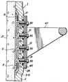
본 발명에 관한 라이닝재(1)는, 외주면이 기밀성이 높은 플라스틱필름(2)으로 피복되고, 또한 저부(3a)가 밀폐된 주머니형상의 수지흡수재(3)에, 열경화성 수지(4)(도 14 참조)를 함침시켜서 구성되고, 수지흡수재(3)의 중간 높이부분(3b)은맨홀(21)의 이음쇠부(21a)(도 15 참조)의 형상에 따르도록 가공(이음쇠가공)되어 있다.The
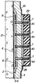
상기 수지흡수재(3)는, 최내측의 부재(3-1)의 외주에 부재(3-2)를 부분적으로 감아서 접속하고, 이 부재(3-2)의 외주의 외주에 별도의 부재(3-3)를 부분적으로 감아서 접착하며, 또한 이 부재(3-3)의 하부외주에 또 별도의 부재(3-4)를 감아서 접착하는 것으로 구성되어 있고, 그 두께는 맨홀(12)의 깊이방향으로 단계적으로 두꺼워 지고 있다. 또, 수지흡수재(3)의 최내측의 부재(3-1)의 중간높이부분(이음쇠가공부분)(3b)의 외주에는 폭이 좁은 부재(3-5)가 감겨서 접착되어 있다. 그리고, 수지흡수부재(3)의 외주면의 스텝부착부에는 복수(도시예에서는 4매)의 직사각형 부재(3-6)가 접착되어 있고, 이들 부재(3-6)에 의해서 수지흡수재(3)의 스텝부착부의 두께가 부분적으로 두껍게 설정되어 있다.The resin
그리고 수지흡수재(3)를 구성하는 부재(3-1∼3-6)는, 폴리에스테르, 나일론, 폴리프로필렌, 아크릴 등의 부직포 또는 유리직물, 유리매트, 유리펠트, 혹은 이들과 상기 부직포의 혼합체로 구성되어 있고, 부재(3-1)의 외주에는 보강재로서의 리본형상의 유리직물(도 5 참조)이 길이방향(맨홀의 깊이방향)으로 접착되어서 조립되어 있다. 또, 수지흡수재(3)의 외표면을 피복하는 상기 플라스틱필름(2)의 재질로서는, 폴리우레탄, 폴리에틸렌 등이 사용되고, 수지흡수재(3)에 함침되는 상기 열경화성 수지(4)로서는, 폴리에스테르수지, 에폭시수지, 비닐에스테르수지 등이 사용된다.The members 3-1 to 3-6 constituting the resin
그런데, 수지흡수재(3)의 스텝부착부에 접착된 상기 직사각형 부재(3-6)의각각에는, 도 2에 상세히 표시하는 바와 같이, 좌우 1쌍의 금속(스테인레스)제 또는 수지제의 스텝부착 베이스(6)가 이것에 설치된 복수의 볼트(7)가 수지흡수재(3)를 관통하여 이것의 내주면으로 돌출하는 형으로 부착되어 있고, 이들 좌우의 스텝 부착 베이스(6)는 금속 또는 수지제의 탄성이 낮은 상하의 평판(8)에 의해서 서로 연결되어 있다. 그리고, 각 스텝부착 베이스(6)에는 합계 8개의 볼트(7)가 2열 4단으로 배열되어서 부착되어 있다.By the way, in each of the said rectangular member 3-6 adhering to the step attachment part of the resin
또, 도 1에 표시하는 바와 같이, 수지흡수재(3)의 외주에 접착된 최상단의 직사각형 부재(3-6)의 좌우에는 금속(스테인레스)제 또는 수지제의 2개의 충전구가 형성된 베이스(9)가 부착되어 있다. 즉, 도 3에 상세하게 표시하는 바와 같이, 충전구가 형성된 베이스(9)는, 이것에 형성된 충전구(10)와 4개의 볼트(11)가 수지흡수재(3)를 관통하여 이것의 내주면으로 돌출하는 형으로 부착되어 있다.As shown in Fig. 1, the
다음에, 상기 구성을 가지는 라이닝재(1)의 제조방법을 도 4 내지 도 14에 기초하여 설명한다. 그리고, 도 4 내지 도 14는 본 발명에 관한 라이닝재(1)의 제조방법을 그 공정순으로 표시하는 설명도이다.Next, the manufacturing method of the
도 1에 표시하는 라이닝재(1)의 제조에 있어서는, 도 4에 표시하는 부직포(3-1')를 접어서 2장 겹침으로 하고, 이것을 맨홀(21)(도 15 참조)의 형상으로 성형한 후, 도 5에 표시하는 바와 같이, 맞춤단부 둘레를 봉제한다. 그리고, 부직포(3-1')의 외표면에 복수의 리본형상 유리직물(5)을 길이방향(맨홀(12)의 깊이방향)으로 접착한다. 그리고, 이 유리직물(5)은 라이닝재(1) 전체의 신장을 억제하여 라이닝재(1)의 치수를 안정시키기 위한 것으로, 이것을 부직포(3-1')내에 미리짜 넣어도 좋다.In the manufacture of the
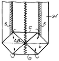
다음에, 부직포(3-1')의 저부를 도 6에 표시하는 바와 같이, 정방형으로 되도록 접고, 그후, 도 6의 쇄선(a,b)을 경계로 하여 정방형의 저부를 도 7에 표시하는 바와 같이 정점 A부와 B부가 접촉하도록 접고, 그 접은 부분의 주위를 용착 또는 접착한다. 그 후, 부직포(3-1')의 저부를 변(C)과 변(D)이 겹치도록 도 7의 쇄선(c)을 경계로 하여 접어, 도 8에 표시하는 주머니형상의 부재(3-1)를 얻는다.Next, as shown in FIG. 6, the bottom of the nonwoven fabric 3-1 'is folded to have a square shape, and then the bottom of the square is shown in FIG. 7 with the dashed lines a and b shown in FIG. As described above, the vertices A and B are folded to contact each other, and the surroundings of the folded portions are welded or bonded. Thereafter, the bottom of the nonwoven fabric 3-1 'is folded around the dashed line c in FIG. 7 so that the sides C and the sides D overlap, and the bag-shaped member shown in FIG. 8 (3- Get 1)
이상과 같이 하여 주머니형상의 부재(3-1)가 얻어지면, 도 8에 표시하는 바와 같이, 부재(3-1)의 이음쇠가공부분에 폭이 좁은 띠형상의 부직포(3-5')를 감는 동시에, 동일한 부재(3-1)의 이음쇠가공부분보다도 아래의 부위의 외주에 띠형상의 부직포(3-2')를 감아서 이들을 융착 또는 접착하고, 도 9에 표시하는 바와 같이, 부재(3-1)의 외주에 부재(3-5)와 (3-2)를 포갠다. 마찬가지로 하여 도 9에 표시하는 바와 같이, 부재(3-2)의 하부 외주에 띠형상의 부직포(3-3')를 감아서 이것을 용착 또는 접착하고, 도 10에 표시하는 바와 같이 부재(3-2)의 하반부 외주에 부재(3-3)를 포개고, 또한, 이 부재(3-3)의 하반부 외주에 띠형상의 부직포(3-4')를 감아서 이것을 용착 또는 접착하여 부재(3-3)의 하반부 외주에 부재(3-4)를 겹치면, 도 11에 표시하는 바와 같이, 부재(3-1∼3-5)로 구성되는 수지흡수재(3)가 얻어지고, 그 두께는 부재(3-2,3-3,3-4)에 의해 맨홀(21)의 깊이방향으로 단계적으로 두껍게 되어 있다. 그리고, 부재(3-5)는 라이닝재(1) 전체의 단면 2차 모멘트를 크게 하여 그 라이닝재(1)의 변형을 방지하기 위한 것이다.When the bag-shaped member 3-1 is obtained as described above, as shown in Fig. 8, a narrow belt-shaped nonwoven fabric 3-5 'is attached to the fitting processing portion of the member 3-1. At the same time, the band-shaped nonwoven fabric 3-2 'is wound around the outer periphery of the portion below the fitting processing portion of the same member 3-1, and these are fused or bonded, and as shown in Fig. 9, the member ( The members 3-5 and 3-2 are stacked on the outer circumference of 3-1). Similarly, as shown in FIG. 9, the strip | belt-shaped nonwoven fabric 3-3 'is wound around the lower outer periphery of the member 3-2, and this is welded or adhere | attached, and as shown in FIG. The member 3-3 is superimposed on the outer periphery of the lower half of 2), and a band-shaped nonwoven fabric 3-4 'is wound around the outer periphery of the lower half of the member 3-3 and welded or bonded to the member 3-. When the member 3-4 is overlapped on the outer periphery of the lower half of 3), as shown in Fig. 11, the resin
상기 바와 같이 해서 수지흡수재(3)가 얻어지면, 도 11에 표시하는 바와 같이, 그 외주의 스텝부착부에 복수의 직사각형 부재(3-6)가 접착되고, 각 직사각형 부재(3-6)에 상기 스텝부착 베이스(6)가 부착됨과 아울러, 수지흡수재(3)의 상부의 2곳에 상기 충전구가 형성된 베이스(9)가 부착된다(도 2 및 도 3 참조).When the resin
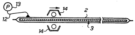
다음에, 주머니형상의 수지흡수재(3)의 전체를 편평하게 한 후, 도 12에 표시하는 바와 같이, 한쪽 끝이 폐쇄된 주머니형상의 플라스틱필름(2)으로 수지흡수재(3)의 전체를 피복하고, 수지흡수재(3)의 한쪽 끝을 진공호스(12)를 통하여 진공펌프(13)에 접속한다. 그리고, 진공펌프(13)를 구동하여 수지흡수재(3)를 진공흡인하면, 도 13에 표시하는 바와 같이, 플라스틱필름(2)이 수지흡수재(3)에 밀착하고, 이 상태로 유지한 채로, 상하 1쌍의 히터(14)를 도 13의 화살표방향(우측)으로 소정의 속도로 이동시키면, 플라스틱필름(2)이 가열되고, 그 플라스틱필름(2)이 수지흡수재(3)의 외주에 한쪽 끝부터 다른 쪽 끝으로 향해서 융착되어 가고, 플라스틱 필름(2)이 수지흡수재(3)의 전체 길이에 걸쳐서 용착되면, 상기한 바와 같이 수지흡수재(3)의 외주면이 플라스틱필름(2)에 의해서 피복된다.Next, after the entire bag-shaped resin
상기 바와 같이 수지흡수재(3)의 외주면이 플라스틱필름(2)에 의해서 피복되면, 도 14에 표시하는 요령으로 그 수지흡수재(3)에 열경화성 수지(4)가 함침된다.When the outer circumferential surface of the resin
즉, 수지용기(15) 내에 수용된 열경화성 수지(4)를 수지흡수재(3)의 한쪽 끝의 개구부로부터 주입하면서, 진공펌프(13)를 구동하여 수지흡수재(3)를 진공흡인하면, 열경화성 수지(4)는 수지흡수재(3)에 발생하는 부압에 끌려서 그 수지흡수재(3)의 전체에 걸쳐서 균일하게 함침되어, 여기에 도 1에 표시하는 본 발명에 관한 라이닝재(1)가 얻어진다.That is, when the
그리하여, 상기 바와 같이 하여 라이닝재(1)가 얻어지면, 그 라이닝재(1)의 수지흡수재(3)에 함침된 열경화성 수지(4)가 열에 의해서 경화되지 않도록, 라이닝재(1)는 수지흡수재(3)에 플라스틱필름(2)이 피복된 상태로 빙수 중에 침지되어서 시공현장으로 반송되지만, 이때, 라이닝재(1)의 수지흡수재(3)는 기밀성이 높은 플라스틱필름(2)에 의해서 피복되어 있기 때문에, 수지흡수재(3)로의 빙수의 침입이 방지되어, 수지흡수재(3)에 함침된 열경화성 수지(4)는 안정한 미 경화상태로 유지된다.Thus, when the
그리고, 라이닝재(1)가 시공현장에 반입되어, 그 라이닝재(1)를 사용하여 라이닝작업을 행함에 있어서 플라스틱필름(2)의 폐색단이 일직선으로 절개되면, 수지흡수재(3)의 단부(저부)(3a)가 개방되고, 라이닝재(1)는 도 1에 표시하는 바와 같이 주머니형상으로 펼쳐진다.Then, when the
다음에, 이상과 같이 하여 얻어지는 라이닝재(1)를 사용하여 시공되는 본 발명에 관한 맨홀라이닝공법을 도 15 내지 도 26에 기초하여 설명한다. 그리고, 도 15 내지 도 19는, 본 발명에 관한 맨홀라이닝공법을 그 공정순으로 표시하는 단면도, 도 20은 라이닝중의 스텝부착 베이스의 상태를 표시하는 단면도, 도 21은 라이닝중의 충전구가 형성된 베이스의 상태를 표시하는 단면도, 도 22는 도 21의 화살표가 가리키는 X방향의 도면, 도 23은, 라이닝후의 스템부착 베이스의 상태를 표시하는 단면도, 도 24는 스텝의 부착상태를 표시하는 단면도, 도 25는 동일한 사시도, 도 26은 충전재의 주입상태를 표시하는 단면도이다.Next, the manhole lining method which concerns on this invention constructed using the
본 발명에 관한 라이닝공법에 있어서는, 도 15에 표시하는 바와 같이,관로(20)내의 맨홀(21)을 끼우는 부분(맨홀(21)의 상류측과 하류측의 2개소)에 지수플러그(22,23)가 설치되어, 양 지수플러그(22,23)의 속을 통수호스(24)가 통과하여 관로(20) 내의 지수플러그(22)의 상류측과 지수플러그(23)의 하류측이 그 통수호스(24)에 의해서 연이어 통한다. 그리고, 관로(20) 내의 양 지수플러그(22,23)로 끼워지는 부분에는, 톱밥, 왕겨 등의 충전재(25)가 충전된다. 그리고, 맨홀(21)의 라이닝에 있어서는, 맨홀(21)의 내주벽에 부착되어 있던 도면에 표시하지 않은 스텝은 절단되어서 제거된다.In the lining method according to the present invention, as shown in Fig. 15, the
그런데, 맨홀(21)의 상단부에는 상방을 향해서 조여지는 이음쇠부(21a)가 형성되어 있고, 그 맨홀(21) 속에는 라이닝재(1)가 지상측으로부터 삽입되어서 그 저부(1a)가 맨홀(21)의 저부(반전부(21b), (도 19 참조)) 상에 맞닿도록 설치된다. 그리고, 라이닝재(1)의 상단개구부는, 지상에 설치된 스테이지(26)에 의해서 지지된 반전노즐(27)의 하단 외주부에 부착된다. 그리고, 이때, 도 20에 표시하는 바와 같이, 각 스텝부착 베이스(6)의 볼트(7)의 수지흡수재(3)의 내주면측으로 돌출하는 부분에는 금속(스테인레스)제 또는 수지제의 판(28)이 통해지고, 각 볼트(7)의 머리부분에는, 고무판(29)에 지지된 캡(30)이 피복부착된다. 또, 도 21에 표시하는 바와 같이, 상기 각 충전재부착 베이스(9)의 충전구(10) 및 볼트(11)의 수지흡수재(3)의 내주면측으로 돌출하는 부분에는 금속(스테인레스)제 또는 수지제의 스톱퍼(31)와 판(32)이 통하고 있고, 판(32)은 볼트(11)에 나착된 너트(33)에 의해 조여져 수지흡수재(3)를 충전구가 형성된 베이스(9)와의 사이에서 협지하고 있고, 충전구(10)는 이것에 나사부착된 캡(34)에 의하여 피복부착된다. 또한, 도21에 표시하는 바와 같이, 상기 각 충전구가 형성된 베이스(9)의 충전구(10) 및 볼트(11)의 수지흡수재(3)의 내주면측으로 돌출하는 부분에는, 금속(스테인레스)제 또는 수지제의 스톱퍼(31)와 판(32)이 통하여 있고, 판(32)은 볼트(11)에 나사결합된 너트에 의해서 조여져서, 수지흡수재(3)를 충전구가 형성된 베이스(9)와의 사이에 끼우고 있고, 충전구(10)는 이것에 나사결합된 캡(34)에 의해서 폐쇄되어 있다.By the way, the upper end part of the
그리하여, 도 15에 표시하는 바와 같이, 상기 반전노즐(27)의 하단 외주부에는, 기밀성이 높은 플라스틱튜브로 이루어진 관형상의 인라이너(35)의 한쪽 끝이 접혀져 부착되어 있고, 상기 바와 같이, 라이닝재(1)의 맨홀(21) 속으로의 삽입이 종료되면, 인라이너(35)의 접혀진 부분의 내측으로 급수호스로부터 물이 주입된다. 그러면, 인라이너(35)는 물의 압력(중량)을 받아서 반전하면서 라이닝재(1) 속을 하방으로 향해서 삽입되어 간다.Thus, as shown in Fig. 15, one end of the
그리고, 상기 인라이너(35)의 라이닝재(1)내로의 반전삽입이 종료하면, 그 인라이너(35)의 말단부에 부착된 온수호스(37)가 도 16에 표시하듯이 인라이너(35)내로 끌려들어 간다.Then, when the reversal insertion of the
다음에, 도 16에 표시하는 바와 같이, 상기 반전노즐(27)의 상단개구부에 캡(38)을 피복하여 이것을 고정시키면, 인라이너(35)내에는 기밀공간(S)이 형성된다.Next, as shown in FIG. 16, when the
그리하여, 상기 밀폐공간(S) 내에는 상기 온수호스(37)와 배수호스(39)가 끌려 들어가 있고, 배수호스(39)의 밀폐공간(S)외로 연출하는 부분의 단부는, 지상에 설치된 온수조(40)의 상방으로 개구되어 있다.Thus, the
그리고, 상기 온수조(40)의 하부로부터 도출하는 급수파이프(41)는 보일러(42)의 입구에 접속되어 있고, 그 급수파이프(41)의 도중에는 온수펌프(43)가 설치되어 있다. 그리고, 보일러(42)의 출구측에는 상기 온수호스(37)의 한쪽 끝이 접속되어 있다.The water supply pipe 41 drawn from the lower part of the
또, 상기 캡(38)에는, 콤프레서(44)로부터 도출하는 공기호스(45)가 접속되어있는 것 외에, 밀폐공간(S)의 내압을 계측하기 위한 압력계(46)가 부착되어 있다.The
그리하여, 상기 콤프레서(44)를 구동하여 압축공기를 공기호스(45)로부터 밀폐공간(S) 내로 공급하면, 인라이너(35)와 라이닝재(1)는 압축공기의 압력에 의해서 맨홀(21)의 내주벽으로 압압된다. 그리고 이때, 라이닝재(1)에 함침되어 있는 미경화의 액상 열경화성 수지(4)는 압축공기의 압력에 의해서 스며 나와서 라이닝재(1)의 하단으로부터 톱밥이나 왕겨 등의 상기 충전재(25) 상에 적하한다.Thus, when the
다음에, 상기 상태를 유지한 채로, 보일러(42)와 온수펌프(43)를 구동하면, 온수조(40) 속의 물은 온수펌프(43)에 의하여 보일러(42)에 공급되고, 그 보일러(42)에 의해서 소정 온도로 가열된 후, 온수호스(37)를 통해서 밀폐공간(S) 내로 공급된다. 즉, 온수호스(37)를 흐르는 온수는, 온수호스(37)의 밀폐공간(S) 내로 향하는 부분으로 개구하는 복수의 분사구(37a)로부터 밀폐공간(S) 내로 샤워모양으로 분출하여 라이닝재(1)의 가열에 공급된다.Next, when the
그리고, 라이닝재(1)의 가열에 공급되어서 온도가 내려간 온수는 낙하하여 밀폐공간(S) 내의 저부에 고이고, 이 고인 온수는 밀폐공간(S)의 내압에 의해서 가압되어서 배수호스(39)를 통해서 온수조(40)로 되돌아가고, 온수펌프(43)에 의해서 재차 보일러(42)에 공급되어서 가열되고, 이후, 상기와 동일한 작용을 반복한다.Then, the hot water supplied to the heating of the
이상과 같이, 온수를 순환시키면서 이것을 온수호스(37)로부터 샤워링시키면, 라이닝재(1)가 가열되어서 이것에 함침된 열경화성 수지(4)가 균일하게 경화한다. 이와 같이, 라이닝재(1)에 함침된 열경화성 수지(4)가 경화하면, 도 17에 표시하는 바와 같이, 인라이너(35)를 상방으로 끌어서 이것을 라이닝재(1)에서 제거한다. 그러면, 맨홀(21)의 내주벽과 저부(반전부(21b))는, 경화한 라이닝재(1)에 의해서 라이닝되어 보수된다.As described above, when this is showered from the
그후, 도 18 및 도 19에 표시하는 바와 같이, 라이닝재(1)의 관로(20)의 일부를 피복하는 부분을 절제하여, 그 절제구멍을 에폭시수지 등의 퍼티접착한다.Then, as shown in FIG. 18 and FIG. 19, the part which covers a part of the
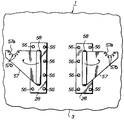
또, 상기 바와 같이, 맨홀(21)의 내주벽과 저부(반전부(21b))가 라이닝재(1)에 의해서 라이닝되면, 도 20에 표시하듯이, 각 스텝부착 베이스(6)의 볼트(7)의 머리부분에 피복부착되어 있던 캡(30)이 고무판(29)과 함께 제거된다. 그러면, 도 23에 표시하듯이, 각 스텝부착 베이스(6)의 볼트(7)가 라이닝재(1)의 수지흡수재(3)의 내주면으로 돌출하기 때문에, 도 24 및 도 25에 표시하듯이, 승강용의 스텝(47)을 볼트(7)를 이용하여 부착한다.As described above, when the inner circumferential wall and the bottom (inverting
즉, 상기 각 스텝(47)에는 좌우 1쌍의 부착판(48)이 설치되어있고, 이들 부착판(48)은 라이닝재(1)의 내측으로부터 볼트(7)에 통과되어, 상기 판(28)에 포개어 합쳐지고, 각 볼트(7)에 나사결합되는 너트(49)를 조임으로써 판(28)에 부착되고, 이것에 의해서 스텝(47)은 스텝부착 베이스(6)를 통하여 라이닝재(1)에 부착되어서 지지된다.That is, each said
상기 바와 같이, 각 스텝(47)은, 종래와 같이 맨홀(21)의 벽에 부착되는 것이 아니고, 스텝부착 베이스(6)를 통하여 라이닝재(1)에 부착되고, 더욱이, 그 스텝부착 베이스(6)가 부착되는 부분의 라이닝재(1)의 두께는 직사각형 부재(3-6)에 의하여 부분적으로 두껍게 되어 있기 때문에, 맨홀(21)의 벽의 노후화가 심한 경우라도, 그 스텝(47)을 충분한 강도로 강고하게 부착할 수 있고, 그 스텝(47)에 작용하는 하중(작업자의 체중)을 라이닝재(1) 전체로 충분히 받을 수 있다. 또 스텝(47)은 라이닝재(1)에 미리 부착된 스텝부착 베이스(6)의 볼트(7)를 이용하여 간단하게 부착할 수 있기 때문에, 종래와 같이 경화한 라이닝재(1)에 후가공에 의하여 스텝부착구멍을 뚫을 필요가 없어지고, 작업의 부담이 경감되어서 생력화를 도모할 수 있다.As described above, each
한편, 맨홀(21)의 라이닝에 공급된 라이닝재(1)가 경화한 후에, 그 라이닝재(1)가 열수축하는 것에 의하여, 도 26에 표시하는 바와 같이, 맨홀(21)과 라이닝재(1)의 사이에 틈새가 발생하기 때문에, 그 틈새에 충전재(50)를 주입할 필요가 있으나, 본 실시예에서는, 충전재(50)의 주입은 라이닝재(1)에 미리 부착되어있던 충전구가 형성된 베이스(9)를 이용하여 다음과 같이 행하여진다.On the other hand, after the
즉, 도 19 및 도 26에 표시하는 바와 같이, 충전구가 형성된 베이스(9)의 충전구(10)를 막고 있던 캡(34)(도 21 및 도 22 참조)를 제거하고, 그 충전구(10)에 충전재 주입호스(51)의 앞부분에 부착된 플러그(52)를 나사결합함으로써, 그 충전구(10)에 충전재 주입호스(51)를 접속하고, 튜브(53)(도 19 참조)에 수용된충전재(50)를 짜내서 이것을 충전재주입호스(51)로부터 충전구가 형성된 베이스(9)의 충전구(10)를 거쳐서 맨홀(21)과 라이닝재(1) 사이의 틈새에 주입하면, 틈새가 충전재(50)에 의해 묻히고, 그 충전재(50)가 경화됨으로써, 라이닝재(1)가 맨홀(21)의 벽과 접합 일체화된다. 그리고, 충전재(50)로서는, 시멘트, 모르타르, 수지(폴리에스테르, 비닐에스테르, 에폭시수지, 우레탄 등), 수지모르타르 등이 사용된다.That is, as shown in FIG. 19 and FIG. 26, the cap 34 (refer to FIG. 21 and FIG. 22) which blocked the filling
그리하여, 본 실시예에 의하면, 라이닝재(1)에 미리 부착된 충전구가 형성된 베이스(9)의 충전구(10)에 충전재 주입호스(51)를 접속하여, 충전재(50)를 맨홀(21)과 라이닝재(1) 사이의 틈새에 주입할 수가 있기 때문에, 종래와 같이 경화한 라이닝재(1)에 후가공에 의해서 충전구를 뚫을 필요가 없어져서, 작업의 부담이 경감되어서 생력화가 도모된다.Thus, according to this embodiment, the
그 외, 본 실시예에 의하면, 노후화한 맨홀(21)의 내주벽이 라이닝재(1)에 의해서 라이닝되어서 보수되지만, 도 18에 표시하는 바와 같이, 라이닝재(1)의 두께가 맨홀(21)의 깊이방향으로 (t1, t2, t3, t4)로 단계적으로 두껍게 되어 있기 때문에(t1<t2<t3<t4), 맨홀(21)의 깊이방향으로 점차 커지는 외압에 대하여, 라이닝재(1)가 강도적으로 충분히 견딜수 있게 된다.In addition, according to the present embodiment, the inner circumferential wall of the
또, 이상 설명한 본 발명에 관한 맨홀라이닝공법에 있어서는, 맨홀(21)의 내주벽뿐만 아니라, 저부(21b)도 라이닝재(1)에 의해서 라이닝할 수 있는 동시에, 인라이너(35)의 라이닝재(1)로의 반전삽입이 종료한 후에 압축공기압을 밀폐공간(S)내로 작용시켰을 때에 맨홀(21)의 이음쇠부(21a)에 작용하는 압축공기압에 의해서 라이닝재(1)가 윗방향으로 들어 올려지도록 하여도, 라이닝재(1)의 저부(1a)에 작용하는 압축공기압에 기인한 아래방향의 힘에 의해서 그것이 저지되기 때문에, 라이닝작업을 안정하게 행할 수 있다.Moreover, in the manhole lining method which concerns on this invention demonstrated above, not only the inner peripheral wall of the
그리고, 본 발명에 있어서는, 라이닝재(1)와 인라이너(35)는 별체로 구성되기 때문에, 라이닝재(1)의 이음쇠가공이 비교적 용이하게 이루어지고, 그 라이닝재(1)의 제조가 간단화한다. 그리고, 맨홀(21)내에 삽입된 라이닝재(1) 내로 반전삽입되는 인라이너(35)의 지름을 라이닝재(1)의 이음쇠부(21a)의 지름보다도 크게 하여 두면, 그 인라이너(35)에 주름이 발생하여도, 라이닝재(1)가 경화한 후에 그 인라이너(35)는 제거되기 때문에, 하등의 문제가 발생하지 않는다.In the present invention, since the
또한, 일련의 라이닝작업이 종료한 후, 지수플러그(22,23)와 통수호스(24)를 관로(20) 내로부터 제거하면, 관로(20) 내에 남은 충전재(25)는 하수 등에 의해서 관로(20) 내를 하류로 향해서 흐르기 때문에, 라이닝작업 중에 그 충전재(25) 상에 적하한 경화성 수지(4)도 충전재(25)와 함께 흘러나간다. 이 때문에, 관로(20) 내로 열경화성 수지(4)가 늘어져서 이것이 경화하는 일이 없어, 경화한 수지(4)의 제거작업도 불필요하게 된다.In addition, after the series of lining operations are completed, the water plugs 22 and 23 and the
또, 본 발명에 관한 맨홀라이닝공법에 의하면, 라이닝재(1)에 함침된 열경화성 수지(4)는 온수호스(37)로부터 샤워링되는 온수에 의해서 효율좋게 가열되기 때문에, 그 열경화성 수지(4)는 약간의 열에너지로 가열되어서 균일하게 경화된다. 따라서, 보일러(42)나 온수펌프(43) 등의 가열, 순환설비의 소형화를 도모할 수가있다.Moreover, according to the manhole lining method which concerns on this invention, since the
그 외, 본 발명에 관한 맨홀라이닝공법에 있어서는, 맨홀(21)의 라이닝작업중이라도, 하수 등은 통수호스(24)를 통해서 관로(20) 내를 그대로 흐르기 때문에, 종래와 같이 하수 등을 맨홀의 상류측에서 펌프로 퍼올려서 다른 장소에 흘리는 작업이 불필요하게 되어, 작업성이 훨씬 높아진다.In addition, in the manhole lining method according to the present invention, even during the lining operation of the
그리고, 이상의 실시예에 있어서는, 라이닝재에 함침된 열경화성 수지의 가열경화의 수법으로서 온수의 샤워링을 사용하였으나, 온수의 주입이나, 순환 혹은 스팀에 의한 가열방법을 채용하여도 좋다. 또, 라이닝재에 함침되는 열경화성 수지로서는, 열경화성 수지 이외에, 광경화성 수지 등을 사용할 수도 있다.In the above embodiment, hot water showering was used as a method of heat curing of the thermosetting resin impregnated with the lining material, but hot water injection, circulation, or heating by steam may be adopted. Moreover, in addition to a thermosetting resin, photocurable resin etc. can also be used as a thermosetting resin impregnated with a lining material.
(실시예2)Example 2
다음에, 본 발명의 실시예(2)를 도 27 및 도 28에 기초로하여 설명한다. 그리고, 도 27은 라이닝중의 스텝부착 베이스의 상태를 표시하는 단면도, 도 28은 스텝의 부착상태를 표시하는 단면도이고, 이들 도면에 있어서는 도 20 및 도 24에 표시한 것과 동일한 요소에는 동일 부호를 붙이고 있다.Next, Embodiment (2) of this invention is demonstrated based on FIG. 27 and FIG. Fig. 27 is a sectional view showing the state of the step mounting base during lining, and Fig. 28 is a sectional view showing the state of attaching the step. In these figures, the same elements as those shown in Figs. 20 and 24 are given the same reference numerals. I put it.
본 실시예에 있어서는, 각 스템부착 베이스(6)에는 4개의 너트(55)가 일체로 형성되어 있고, 이들의 너트(55)는 수지흡수재(3)의 내주면측으로 돌출하여 있고, 라이닝 시공시에는, 도 27에 표시하듯이, 수지흡수재(3)의 내측으로부터 금속(스테인레스) 또는 수지제의 스톱퍼(31)와 판(28)이 너트(55)에 통과하고 있다. 그리고 판(28)은, 너트(55)에 나착된 볼트(56)에 의하여 조여져서 수지흡수재(3)를 스텝부착 베이스(6)와의 사이에서 협지하고 있다. 그리고, 상기 실시예1과 마찬가지로,라이닝에 있어서는 각 볼트(56)의 머리부분에는 고무판(29)에 지지된 캡(30)이 피복부착된다.In the present embodiment, four stems 55 are integrally formed in each
그리하여, 맨홀(21)의 내주벽과 저부가 라이닝재(1)에 의해서 라이닝되면, 도 27에 표시하듯이 각 볼트(56)의 머리부분에 피복부착되어 있던 캡(30)이 고무판(29)과 함께 제거됨과 아울러, 볼트(56)도 제거되고, 도 28에 표시하듯이 볼트(56)를 너트(55)로 조임으로써 승강용의 스텝(47)을 부착한다.Thus, when the inner circumferential wall and the bottom of the
즉, 상기 각 스텝(47)에는 좌우 1쌍의 부착판(48)이 설치되어 있고, 이들의 부착판(48)은 라이닝재(1)의 내측으로부터 상기 판(28)에 포개어 합쳐지고, 부착판(48)에 삽입통과되는 볼트(56)를 너트(55)로 조임으로써 판(28)에 부착되고, 이것에 의해서 스텝(47)은 스텝부착 베이스(6)를 통하여 라이닝재(1)에 부착되어서 지지된다.That is, each said
따라서, 본 실시예에 있어서도, 각 스텝(47)은 종래와 같이 맨홀(21)의 벽에 부착되는 것이 아니고, 스텝부착 베이스(6)를 통하여 라이닝재(1)에 부착되고, 더욱이, 그 스텝부착 베이스(6)가 부착되는 부분의 라이닝재(1)의 두께는, 직사각형 부재(3-6)에 의해서 부분적으로 두껍게 되어 있기 때문에, 맨홀(21)의 벽의 노후화가 심한 경우라도, 그 스텝(47)을 충분한 강도로 강고하게 부착할 수 있고, 그 스텝(47)에 작용하는 하중(작업자의 체중)을 라이닝재(1) 전체로 충분히 받을 수 있다.Therefore, also in this embodiment, each
또, 스탭(47)은 라이닝재(1)에 미리 부착된 스텝부재부착 베이스(6)의 너트(55)를 이용해서 간단하게 부착되기 때문에, 종래와 같이 경화한 라이닝재(1)에 후가공에 의하여 스텝부착구멍을 뚫을 필요가 없어져서, 작업의 부담이 경감되어서 생력화가 도모된다.In addition, since the
(실시예3)Example 3
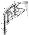
다음에, 본 발명의 실시예(3)를 도 29 내지 도 32에 기초하여 설명한다. 그리고, 도 29는 본 실시예에 관한 맨홀용의 라이닝재를 내주면측에서 본 부분정면도, 도 30은 라이닝중의 스텝부착 베이스의 상태를 표시하는 단면도, 도 31은 스텝의 부착상태를 표시하는 사시도, 도 32는 스텝의 바 부착부의 구조를 표시하는 부분 파단면도이다.Next, Example (3) of this invention is demonstrated based on FIG. 29-32. 29 is a partial front view of the lining material for the manhole according to the present embodiment as seen from the inner circumferential surface side, FIG. 30 is a sectional view showing the state of the stepped base during lining, and FIG. 32 is a fragmentary sectional view showing the structure of the bar attachment portion of the step.
본 실시예에 있어서는, 도 29에 표시하는 바와 같이, 라이닝재(1)의 수지흡수재(3)의 내주면에 좌우 1쌍의 판(28)이 상기 실시예2와 동일한 구조에 의해서 깊이방향으로 복수조(도 29에는 1조의 판(28)을 표시함) 적당한 간격으로 부착되어 있다. 즉, 도 30에 표시하는 바와 같이, 판(28)은 스텝부착 베이스(6)에 형성된 너트(55)에 나사결합된 볼트(56)에 의하여 수지흡수재(3)를 스텝부착 베이스(6)외의 사이에 끼워지도록 부착되어 있다. 그리고, 도 30에 있어서, 8은 좌우 스텝부착 베이스(6)를 연결하는 평판이고, 31은 스톱퍼이다.In this embodiment, as shown in Fig. 29, a pair of left and right pairs of
그리하여, 상기 각 판(28)에는, 도 31에 표시하는 스텝(47)의 일부를 구성하는 대략 삼각형상의 지지판(57)이 힌지(58)에 의하여 회전가능하게 지지되어 있고, 라이닝재에 있어서는 도 29에 표시하듯이 지지판(57)은 도시한 화살표방향으로 폐쇄되어 수지흡수재(3)의 내주면을 따라서 평면을 구성하고 있다.Thus, each of the
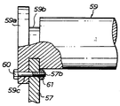
그런데, 도 30에 상세하게 표시하는 바와 같이, 각 부착판(57)의 윗면에는반원형상의 축받이부(57a)가 형성되어 있고, 이 축받이부(57a)의 주위에는 복수(도시예에서는 6개)의 볼트 삽입통과구멍(57b)이 형성되어 있다.By the way, as shown in detail in FIG. 30, the
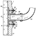
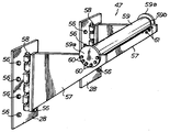
이상에 있어서, 맨홀(21)의 내주벽과 저부가 라이닝재(1)에 의해서 라이닝되면, 경화한 라이닝재(1)의 내주면측에 부착되어있는 각 지지판(57)을 도 30에 표시하듯이 개방하고, 도 31에 표시하는 바와 같이, 좌우 1쌍의 부착판(57) 사이에 고리봉형상의 바(59)를 가설고정하여 스텝(47)을 조립한다.In the above, when the inner circumferential wall and the bottom of the
즉, 도 32에 상세하게 표시하는 바와 같이, 바(59)의 양단에는 플랜지부(59a)가 형성되고, 그 내측에는 홈(59b)이 전체 둘레에 걸쳐서 형성되어 있고, 그 바(59)는, 그 홈(59b)을 각 부착판(57)의 축받이부(57a)에 끼워 넣고, 플랜지부(59a)와 부착판(57)의 각각에 형성된 볼트 삽입통과구멍(59c,57b)에 삽입통과하는 볼트(60)를 너트(61)로 조임으로써, 그 양단이 부착판(57)에 부착된다.That is, as shown in detail in FIG. 32,
그리하여, 본 실시예에 있어서도, 각 스텝(47)은, 종래와 같이, 맨홀(21)의 벽에 부착되는 것이 아니고, 스텝부착 베이스(6)를 통하여 라이닝재(1)에 부착되고, 더욱이, 스텝부착 베이스(6)가 부착되는 부분의 라이닝재(1)의 두께는 직사각형 부재(3-6)에 의하여 부분적으로 두껍게 되어 있기 때문에(도 30 참조), 맨홀(21)의 벽의 노후화가 심한 경우라도, 그 스텝(47)을 충분한 강도로 강고하게 부착할 수 있고, 상기 실시예 1 및 2와 동일한 효과가 얻어진다.Therefore, also in this embodiment, each
이상의 설명에서 명백한 바와 같이, 청구항 제1항∼제7항 기재의 맨홀용 라이닝재를 사용하여 시공되는 청구항 제8항 기재의 발명에 의하면, 승강용 스텝은종래와 같이 맨홀의 벽이 아니라, 스텝부착 베이스를 통하여 맨홀용 라이닝재에 부착되기 때문에, 맨홀의 벽의 노후화가 심한 경우라도, 스텝을 충분한 강도로 강고하게 부착할 수 있고, 그 스텝에 작용하는 하중(작업자의 체중)을 맨홀용 라이닝재 전체로 충분히 받을 수 있다. 또, 스텝은, 맨홀용 라이닝재에 미리 부착된 스텝부착 베이스의 볼트 또는 너트를 이용하여 간단하게 부착할 수 있으므로, 경화한 라이닝재에 후가공에 의해서 스텝부착구멍을 뚫을 필요가 없어져서, 작업의 부담을 경감해서 생력화를 도모할 수가 있다.As apparent from the above description, according to the invention of
청구항 제9항 기재의 발명이 있으면, 맨홀용 라이닝재에 미리 부착된 충전구가 형성된 베이스의 충전구에 충전재 주입호스를 접속하여 충전재를 맨홀과 라이닝재의 틈새에 주입할 수가 있기 때문에, 종래와 같이 경화한 라이닝재에 후가공에 의해서 충전구를 뚫을 필요가 없어져서, 작업의 부담을 경감하여 생력화를 도모할 수가 있다.According to the invention of
청구항 제10항 기재의 발명에 의하면, 라이닝재에 함침된 열경화성 수지는 온수호스로부터 샤워링되는 온수에 의해서 효율좋게 가열되기 때문에, 그 열경화성 수지는 약간의 열에너지로 가열되어서 균일하게 경화한다. 따라서, 가열 ·순환설비의 소형화를 도모할 수 있다.According to the invention of
청구항 제11항 기재의 발명에 의하면, 맨홀의 라이닝작업중이라도, 하수 등의 유체는 통수호스를 통해서 관로 내를 그대로 흐르기 때문에, 종래와 같이 하수등을 맨홀의 상류측에서 펌프로 뿜어 올려서 다른 장소로 흘리는 작업이 불필요하게 되어, 작업성이 훨씬 높아진다.According to the invention of
청구항 제12항 기재의 발명에 의하면, 밀폐공간에 유체압력을 작용시켜서 라이닝재를 맨홀의 내벽에 압압했을 때에 그 라이닝재에 함침된 경화성 수지가 압력에 의해서 스며나와서 라이닝재의 하단으로부터 적하하여도, 그 경화성 수지는 톱밥이나 왕겨 등의 충전재 상에 떨어지기 때문에, 관로 내로 경화성 수지가 늘어져서 이것이 경화하는 일이 없다. 그리고, 충전재 상에 떨어진 경화성 수지는, 라이닝 종료 후에 충전재와 함께 관로 내를 흐르기 때문에 그 제거작업도 불필요하게 된다.According to the invention of
Claims (12)
Applications Claiming Priority (2)
| Application Number | Priority Date | Filing Date | Title |
|---|---|---|---|
| JP96-62735 | 1996-03-19 | ||
| JP8062735A JP2837385B2 (en) | 1996-03-19 | 1996-03-19 | Manhole lining material and manhole lining method |
Publications (2)
| Publication Number | Publication Date |
|---|---|
| KR970064875A KR970064875A (en) | 1997-10-13 |
| KR100443648B1 true KR100443648B1 (en) | 2004-10-14 |
Family
ID=13208943
Family Applications (1)
| Application Number | Title | Priority Date | Filing Date |
|---|---|---|---|
| KR1019970007185A KR100443648B1 (en) | 1996-03-19 | 1997-03-05 | Manhole Lining Material and Manhole Lining Method |
Country Status (9)
| Country | Link |
|---|---|
| US (1) | US6018914A (en) |
| EP (1) | EP0796717B1 (en) |
| JP (1) | JP2837385B2 (en) |
| KR (1) | KR100443648B1 (en) |
| AU (1) | AU712604B2 (en) |
| CA (1) | CA2200262A1 (en) |
| DE (1) | DE69702876T2 (en) |
| DK (1) | DK0796717T3 (en) |
| TW (1) | TW319739B (en) |
Cited By (1)
| Publication number | Priority date | Publication date | Assignee | Title |
|---|---|---|---|---|
| KR100749580B1 (en) | 2006-06-05 | 2007-08-17 | 유용진 | Lining concrete manhole blocks, manufacturing method and installation method of the chemical resin lining manhole blocks which uses the installation structure and this liner of the chemical resin liner |
Families Citing this family (24)
| Publication number | Priority date | Publication date | Assignee | Title |
|---|---|---|---|---|
| KR100395005B1 (en) * | 2001-01-31 | 2003-08-19 | 한국건설기술연구원 | Manhole repairing apparatus and manhole repairing method using the same |
| US7087296B2 (en) * | 2001-11-29 | 2006-08-08 | Saint-Gobain Technical Fabrics Canada, Ltd. | Energy absorbent laminate |
| US7096890B2 (en) | 2002-06-19 | 2006-08-29 | Saint-Gobain Technical Fabrics Canada, Ltd. | Inversion liner and liner components for conduits |
| US7478650B2 (en) * | 2002-06-19 | 2009-01-20 | Saint-Gobain Technical Fabrics Canada, Ltd. | Inversion liner and liner components for conduits |
| US7311964B2 (en) * | 2002-07-30 | 2007-12-25 | Saint-Gobain Technical Fabrics Canada, Ltd. | Inorganic matrix-fabric system and method |
| US6893186B1 (en) * | 2002-08-07 | 2005-05-17 | Steve Tello, Sr. | Manhole cover |
| US20040261343A1 (en) * | 2003-06-26 | 2004-12-30 | Koteskey Gary L. | Molded sectioned riser |
| US7966786B2 (en) * | 2003-06-26 | 2011-06-28 | Sim-Tech Filters, Inc. | Molded sectioned riser and locking cover |
| US7451783B2 (en) * | 2004-04-23 | 2008-11-18 | Shonan Gosei-Jushi Seisakusho K.K. | Position adjusting spacer and method for adjusting the position of a rehabilitating pipe using such |
| US7670086B2 (en) * | 2005-11-23 | 2010-03-02 | Lmk Enterprises, Inc. | Method of repairing a manhole chimney using a stretchable sleeve |
| JP5302696B2 (en) * | 2008-07-11 | 2013-10-02 | 株式会社湘南合成樹脂製作所 | Manhole rehabilitation method |
| JP5678300B2 (en) * | 2010-09-22 | 2015-02-25 | 有限会社横島 | Rehabilitation pipeline inspection method and rehabilitation pipeline inspection method including rehabilitation pipeline inspection process |
| RU2459909C2 (en) * | 2010-10-28 | 2012-08-27 | Павел Иванович Белоконь | Method to raise road manholes in construction of roads |
| US10214345B1 (en) * | 2011-12-12 | 2019-02-26 | Cameron Gordon Howie | Entryway protective collar |
| DE102012102433B4 (en) * | 2012-03-22 | 2014-01-16 | Peter Eschenbrenner | Method and device for rehabilitating a manhole |
| ITRM20130241A1 (en) * | 2013-04-23 | 2014-10-24 | Maremmana Ecologia S R L | METHOD OF WATERPROOFING POZZETTI PASSO D¿UOMO IN WALL |
| US9714735B2 (en) * | 2014-05-27 | 2017-07-25 | LMK Technologies, Inc. | Method of repairing a manhole and pipes |
| CA2968384A1 (en) * | 2014-11-20 | 2016-05-26 | Press-Seal Corporation | Manhole base assembly with internal liner and method of manufacturing same |
| US10214893B2 (en) | 2014-11-20 | 2019-02-26 | Press-Seal Corporation | Manhole base assembly with internal liner and method of manufacturing same |
| DK178948B1 (en) * | 2016-03-14 | 2017-06-26 | Ermo Glasfiber Aps | Lining device |
| JP6183869B2 (en) * | 2016-03-29 | 2017-08-23 | 株式会社アイビルド | Manhole renewal method and manhole new construction method |
| US10688713B1 (en) * | 2019-03-29 | 2020-06-23 | Resinating LLC | Systems and methods for rehabilitating, repairing, and replacing manholes and connected sewer lines |
| US11808003B2 (en) * | 2021-02-01 | 2023-11-07 | Hydro-Klean, Llc | Method of rehabilitating a manhole |
| US11686298B1 (en) * | 2022-03-04 | 2023-06-27 | Dannon Appleyard | Pump guard protective sleeve |
Family Cites Families (21)
| Publication number | Priority date | Publication date | Assignee | Title |
|---|---|---|---|---|
| US29636A (en) * | 1860-08-14 | Improvement in seed-planters | ||
| CS150463B1 (en) * | 1969-04-23 | 1973-09-04 | ||
| US3621623A (en) * | 1970-03-23 | 1971-11-23 | Allan Macmillan Downes | Apparatus for temporarily closing an opening formed at the top of vertical walls of a catch basin manhole or the like |
| US3745738A (en) * | 1971-09-07 | 1973-07-17 | F Singer | Corrosion resistant manhole shaft and method of making same |
| US4038793A (en) * | 1975-01-14 | 1977-08-02 | Juan Armengol Roca | Wall structure |
| DE2605535C2 (en) * | 1976-02-12 | 1978-03-09 | Gerhard 8867 Oettingen Enssle | Method for building manholes, in particular for sewers, and manhole produced using the method |
| US4089139A (en) * | 1976-08-24 | 1978-05-16 | Armco Steel Corporation | Segmented cylindrical reinforced plastic manhole structure |
| US4127990A (en) * | 1977-01-21 | 1978-12-05 | Morrow Otis L | Drainage structure forming method |
| CA1096146A (en) * | 1978-12-20 | 1981-02-24 | Anthony Foscarini | Method of installing manhole safety steps and plugs therefor |
| US4275757A (en) * | 1979-08-06 | 1981-06-30 | Singer Frederic J | Manhole structure and method of making same |
| GB8400233D0 (en) * | 1984-01-05 | 1984-02-08 | Edgealpha Ltd | Lining pipelines and passageways |
| US5106440A (en) * | 1989-01-30 | 1992-04-21 | Tangeman Andrew F | Method for repairing manholes or wetwalls |
| GB8907060D0 (en) * | 1989-03-29 | 1989-05-10 | Craig Philip | Chamber and method of making same,liner and cover therefor |
| US5081802A (en) * | 1990-02-15 | 1992-01-21 | Poly-Tec Products, Inc. | Method and apparatus for lining manhole assemblies and the like |
| JPH07115365B2 (en) * | 1992-04-28 | 1995-12-13 | 筒中プラスチック工業株式会社 | Manufacturing method of lining material for repairing existing human hole in sewer |
| US5405218A (en) * | 1992-05-05 | 1995-04-11 | Foamseal Inc | Method for the repair of existing manholes using elastomeric materials |
| US5303518A (en) * | 1993-02-11 | 1994-04-19 | Strickland Industries, Inc. | Lined manhole assembly and liner |
| JP2554436B2 (en) * | 1993-03-12 | 1996-11-13 | 株式会社湘南合成樹脂製作所 | Tube lining material inversion method |
| US5386669A (en) * | 1993-03-15 | 1995-02-07 | Almeida; Antonio V. | Corrosion resistant leakproof plastic manhole system |
| US5490744A (en) * | 1993-12-08 | 1996-02-13 | Mcneil; Ronald A. | Method and apparatus for inflating and curing a resin impregnated manhole liner |
| JP2857978B2 (en) * | 1994-12-01 | 1999-02-17 | 筒中プラスチック工業株式会社 | Lining material for repairing existing manholes in sewers |
-
1996
- 1996-03-19 JP JP8062735A patent/JP2837385B2/en not_active Expired - Fee Related
- 1996-12-17 TW TW085115595A patent/TW319739B/zh active
- 1996-12-17 US US08/767,622 patent/US6018914A/en not_active Expired - Fee Related
-
1997
- 1997-02-25 DK DK97301204T patent/DK0796717T3/en active
- 1997-02-25 DE DE69702876T patent/DE69702876T2/en not_active Expired - Fee Related
- 1997-02-25 EP EP97301204A patent/EP0796717B1/en not_active Expired - Lifetime
- 1997-03-05 KR KR1019970007185A patent/KR100443648B1/en not_active IP Right Cessation
- 1997-03-18 CA CA002200262A patent/CA2200262A1/en not_active Abandoned
- 1997-03-18 AU AU16367/97A patent/AU712604B2/en not_active Ceased
Cited By (1)
| Publication number | Priority date | Publication date | Assignee | Title |
|---|---|---|---|---|
| KR100749580B1 (en) | 2006-06-05 | 2007-08-17 | 유용진 | Lining concrete manhole blocks, manufacturing method and installation method of the chemical resin lining manhole blocks which uses the installation structure and this liner of the chemical resin liner |
Also Published As
| Publication number | Publication date |
|---|---|
| JPH09254259A (en) | 1997-09-30 |
| DE69702876T2 (en) | 2001-03-01 |
| EP0796717B1 (en) | 2000-08-23 |
| AU1636797A (en) | 1997-09-25 |
| US6018914A (en) | 2000-02-01 |
| TW319739B (en) | 1997-11-11 |
| DK0796717T3 (en) | 2000-10-23 |
| KR970064875A (en) | 1997-10-13 |
| JP2837385B2 (en) | 1998-12-16 |
| AU712604B2 (en) | 1999-11-11 |
| DE69702876D1 (en) | 2000-09-28 |
| CA2200262A1 (en) | 1997-09-19 |
| EP0796717A1 (en) | 1997-09-24 |
Similar Documents
| Publication | Publication Date | Title |
|---|---|---|
| KR100443648B1 (en) | Manhole Lining Material and Manhole Lining Method | |
| KR0178144B1 (en) | Method of lining a branch pipe | |
| JP2554411B2 (en) | Branch pipe lining material and manufacturing method thereof | |
| US7056064B2 (en) | Block unit for repairing flow passage facilities and method of repairing flow passage facilities | |
| JP3839605B2 (en) | Manhole lining material | |
| JP2564087B2 (en) | Resin injection method for pipe lining and pipe repair method | |
| US5736077A (en) | Method for lining a manhole | |
| US7018691B2 (en) | Reinforcing liner, system and method of reinforcing a structure, and reinforced structure thereby | |
| KR100445451B1 (en) | Reinforcing element of retired underground pipes and trenchless repairing method of them | |
| US5503190A (en) | Method for repairing a tubular conduit | |
| RU2471114C2 (en) | Multiple-use device, and method for inverting inserts vulcanised on site | |
| JP2926067B2 (en) | Manhole lining material and manhole lining method | |
| JP2011025456A (en) | Pipe lining method and lining pipe | |
| JP3472077B2 (en) | Manhole lining material and manhole lining method | |
| KR100904450B1 (en) | Tube lining method | |
| KR100347011B1 (en) | Repairing method of retired drain pipes by resin transfer molding | |
| JP2021045948A (en) | Lining material and manufacturing method of lining material | |
| KR200275909Y1 (en) | Fiber Reinforced Plastic Pipe Fitting | |
| KR100491443B1 (en) | Repairing Reinforcing Element of Underground Pipes and Trenchless Repairing Reinforcing Method Using the Same | |
| JP6986743B2 (en) | Pipe rehabilitation method | |
| CA2435831A1 (en) | Block unit for repairing flow passage facilities and method of repairing flow passage facilities | |
| JP2652655B2 (en) | Internal lining method for existing pipes | |
| JP3855095B2 (en) | Pipeline lining method | |
| JP2000015699A (en) | Lining material for manhole, its manufacture and method for lining manhole | |
| JP2002323175A (en) | Manufacturing method of plastic pipe and pipe-lining method |
Legal Events
| Date | Code | Title | Description |
|---|---|---|---|
| A201 | Request for examination | ||
| E701 | Decision to grant or registration of patent right | ||
| GRNT | Written decision to grant | ||
| LAPS | Lapse due to unpaid annual fee |