KR100400144B1 - TRANSMISSION SET CONNECTOR WITH LOCKING COVER AND METHOD OF USING THE SAME - Google Patents
TRANSMISSION SET CONNECTOR WITH LOCKING COVER AND METHOD OF USING THE SAME Download PDFInfo
- Publication number
- KR100400144B1 KR100400144B1 KR1019970702149A KR19970702149A KR100400144B1 KR 100400144 B1 KR100400144 B1 KR 100400144B1 KR 1019970702149 A KR1019970702149 A KR 1019970702149A KR 19970702149 A KR19970702149 A KR 19970702149A KR 100400144 B1 KR100400144 B1 KR 100400144B1
- Authority
- KR
- South Korea
- Prior art keywords
- tubing
- connector assembly
- lid
- predetermined length
- fluid communication
- Prior art date
Links
Images


Classifications
-
- A—HUMAN NECESSITIES
- A61—MEDICAL OR VETERINARY SCIENCE; HYGIENE
- A61M—DEVICES FOR INTRODUCING MEDIA INTO, OR ONTO, THE BODY; DEVICES FOR TRANSDUCING BODY MEDIA OR FOR TAKING MEDIA FROM THE BODY; DEVICES FOR PRODUCING OR ENDING SLEEP OR STUPOR
- A61M39/00—Tubes, tube connectors, tube couplings, valves, access sites or the like, specially adapted for medical use
- A61M39/20—Closure caps or plugs for connectors or open ends of tubes
-
- A—HUMAN NECESSITIES
- A61—MEDICAL OR VETERINARY SCIENCE; HYGIENE
- A61M—DEVICES FOR INTRODUCING MEDIA INTO, OR ONTO, THE BODY; DEVICES FOR TRANSDUCING BODY MEDIA OR FOR TAKING MEDIA FROM THE BODY; DEVICES FOR PRODUCING OR ENDING SLEEP OR STUPOR
- A61M39/00—Tubes, tube connectors, tube couplings, valves, access sites or the like, specially adapted for medical use
- A61M39/10—Tube connectors; Tube couplings
-
- F—MECHANICAL ENGINEERING; LIGHTING; HEATING; WEAPONS; BLASTING
- F16—ENGINEERING ELEMENTS AND UNITS; GENERAL MEASURES FOR PRODUCING AND MAINTAINING EFFECTIVE FUNCTIONING OF MACHINES OR INSTALLATIONS; THERMAL INSULATION IN GENERAL
- F16L—PIPES; JOINTS OR FITTINGS FOR PIPES; SUPPORTS FOR PIPES, CABLES OR PROTECTIVE TUBING; MEANS FOR THERMAL INSULATION IN GENERAL
- F16L37/00—Couplings of the quick-acting type
- F16L37/08—Couplings of the quick-acting type in which the connection between abutting or axially overlapping ends is maintained by locking members
- F16L37/10—Couplings of the quick-acting type in which the connection between abutting or axially overlapping ends is maintained by locking members using a rotary external sleeve or ring on one part
- F16L37/113—Couplings of the quick-acting type in which the connection between abutting or axially overlapping ends is maintained by locking members using a rotary external sleeve or ring on one part the male part having lugs on its periphery penetrating into the corresponding slots provided in the female part
-
- F—MECHANICAL ENGINEERING; LIGHTING; HEATING; WEAPONS; BLASTING
- F16—ENGINEERING ELEMENTS AND UNITS; GENERAL MEASURES FOR PRODUCING AND MAINTAINING EFFECTIVE FUNCTIONING OF MACHINES OR INSTALLATIONS; THERMAL INSULATION IN GENERAL
- F16L—PIPES; JOINTS OR FITTINGS FOR PIPES; SUPPORTS FOR PIPES, CABLES OR PROTECTIVE TUBING; MEANS FOR THERMAL INSULATION IN GENERAL
- F16L37/00—Couplings of the quick-acting type
- F16L37/08—Couplings of the quick-acting type in which the connection between abutting or axially overlapping ends is maintained by locking members
- F16L37/12—Couplings of the quick-acting type in which the connection between abutting or axially overlapping ends is maintained by locking members using hooks, pawls or other movable or insertable locking members
- F16L37/1205—Couplings of the quick-acting type in which the connection between abutting or axially overlapping ends is maintained by locking members using hooks, pawls or other movable or insertable locking members using hooks hinged about an axis placed behind a flange and which act behind the other flange
-
- A—HUMAN NECESSITIES
- A61—MEDICAL OR VETERINARY SCIENCE; HYGIENE
- A61M—DEVICES FOR INTRODUCING MEDIA INTO, OR ONTO, THE BODY; DEVICES FOR TRANSDUCING BODY MEDIA OR FOR TAKING MEDIA FROM THE BODY; DEVICES FOR PRODUCING OR ENDING SLEEP OR STUPOR
- A61M39/00—Tubes, tube connectors, tube couplings, valves, access sites or the like, specially adapted for medical use
- A61M39/10—Tube connectors; Tube couplings
- A61M2039/1027—Quick-acting type connectors
-
- A—HUMAN NECESSITIES
- A61—MEDICAL OR VETERINARY SCIENCE; HYGIENE
- A61M—DEVICES FOR INTRODUCING MEDIA INTO, OR ONTO, THE BODY; DEVICES FOR TRANSDUCING BODY MEDIA OR FOR TAKING MEDIA FROM THE BODY; DEVICES FOR PRODUCING OR ENDING SLEEP OR STUPOR
- A61M39/00—Tubes, tube connectors, tube couplings, valves, access sites or the like, specially adapted for medical use
- A61M39/10—Tube connectors; Tube couplings
- A61M39/14—Tube connectors; Tube couplings for connecting tubes having sealed ends
-
- A—HUMAN NECESSITIES
- A61—MEDICAL OR VETERINARY SCIENCE; HYGIENE
- A61M—DEVICES FOR INTRODUCING MEDIA INTO, OR ONTO, THE BODY; DEVICES FOR TRANSDUCING BODY MEDIA OR FOR TAKING MEDIA FROM THE BODY; DEVICES FOR PRODUCING OR ENDING SLEEP OR STUPOR
- A61M39/00—Tubes, tube connectors, tube couplings, valves, access sites or the like, specially adapted for medical use
- A61M39/22—Valves or arrangement of valves
- A61M39/26—Valves closing automatically on disconnecting the line and opening on reconnection thereof
-
- Y—GENERAL TAGGING OF NEW TECHNOLOGICAL DEVELOPMENTS; GENERAL TAGGING OF CROSS-SECTIONAL TECHNOLOGIES SPANNING OVER SEVERAL SECTIONS OF THE IPC; TECHNICAL SUBJECTS COVERED BY FORMER USPC CROSS-REFERENCE ART COLLECTIONS [XRACs] AND DIGESTS
- Y10—TECHNICAL SUBJECTS COVERED BY FORMER USPC
- Y10S—TECHNICAL SUBJECTS COVERED BY FORMER USPC CROSS-REFERENCE ART COLLECTIONS [XRACs] AND DIGESTS
- Y10S604/00—Surgery
- Y10S604/905—Aseptic connectors or couplings, e.g. frangible, piercable
Abstract
Description
<발명의 배경>BACKGROUND OF THE INVENTION [
본 발명은 소정 길이의 제1 튜빙(tubing)을 소정 길이의 제2 튜빙에 연결하기 위한 커넥터 조립체(connector assembly)에 관한 것이다. 특히, 본 발명은 커넥터 조립체의 하나의 요소와 일체로 형성된 로킹 힌지식 마개(locking hinged closure)와, 2개의 요소가 연결될 때 로킹 힌지식 마개를 개방하는 협동 요소를 구비하는 커넥터 조립체에 관한 것이다.The present invention relates to a connector assembly for connecting a first tubing of a predetermined length to a second tubing of a predetermined length. More particularly, the present invention relates to a connector assembly having a locking hinged closure formed integrally with an element of a connector assembly and a cooperating element opening the locking hinged closure when the two elements are connected.
여러 산업 분야에서, 다양한 적용을 위하여, 유동 경로를 생성 및 제공하는 것이 필요하다. 많은 경우에 있어서, 특히 의료 산업에서, 무균 유체 유동 경로를 생성하는 것이 필요하다.In many industrial applications, for various applications, it is necessary to create and provide flow paths. In many cases, especially in the medical industry, it is necessary to create a sterile fluid flow path.
물론, 의약 분배, 영양물 공급 및 복막 투석 등과 같은 여러 목적을 위하여 환자에게 유체를 분배하는 것이 일반적으로 공지되어 있다. 이러한 유체 분배는 많은 경우에 있어서 무균 유동 경로를 필요로 한다. 이러한 과정은 종종 무균 유동 경로가 분리 및 재연결되는 것을 요구한다.Of course, it is generally known to distribute fluids to patients for various purposes such as medication dispensing, nutrient supply, and peritoneal dialysis. Such fluid distribution requires a sterile flow path in many instances. This process often requires that the sterile flow path be separated and reconnected.
예컨대, 용액을 포함하는 용기에 연결되는 소정 길이의 튜빙을 사용하여 환자에게 용액을 주입하기 위하여 캐뉼러(cannula) 또는 니들(needle)을 사용하는 것이 공지되어 있다. 종종, 용기와 환자 사이에 튜빙을 통해 유체 연통이 가능하게 하기 위하여 어댑터(adaptor) 또는 다른 커넥터가 제공된다. 예컨대, 소정 길이의튜빙의 일단부를 용기에 연결하기 위하여 커넥터가 용기 상의 포트에 마련될 수 있다.For example, it is known to use a cannula or needle to inject a solution into a patient using a length of tubing that is connected to a container containing the solution. Often, an adapter or other connector is provided to enable fluid communication between the container and the patient through the tubing. For example, a connector may be provided at a port on the container to connect one end of a tubing of a predetermined length to the container.
또한, 복막 투석을 위한 것처럼 용액을 환자에게 제공하는 것이 주지되어 있다. 복막 투석에 있어서, 투석 용액은 카테테르(catheter)를 이용하여 복막강 내로 도입된다. 충분한 시간 후에, 투석물(dialysate)과 혈액 사이에 용질 교환이 이루어진다. 혈액으로부터 투석물로의 적당한 삼투 구배를 제공하여 혈액으로부터 물이 빠져나가도록 함으로써 유체가 제거된다. 혈액으로 귀환되는 적당한 산-염기 전해질 및 유체 균형이 이루어지며, 투석 용액은 카테테르를 통해 체강(body cavity)으로부터 간단히 배출된다.It is also well known to provide a solution to the patient as for peritoneal dialysis. In peritoneal dialysis, the dialysis solution is introduced into the multiple membrane cavity using a catheter. After a sufficient time, a solute exchange occurs between the dialysate and the blood. The fluid is removed by providing a proper osmotic gradient from the blood to the dialysate to allow water to escape from the blood. A suitable acid-base electrolyte and fluid balance are returned to the blood, and the dialysis solution is simply vented from the body cavity through the catheter.
이러한 과정은 통상적으로 이러한 환자를 위하여 하루에 3회 또는 4회 반복된다. 따라서, 반복 연결 및 분리가 시스템으로부터 이루어지는 것이 요구된다. 더욱이, 이러한 환자는 신체 내로의 용액의 투여 중에 중단되어 종종 시스템으로부터 분리될 것이 요구된다.This procedure is typically repeated three or four times a day for these patients. Thus, repeated connection and disconnection is required from the system. Moreover, such patients are interrupted during administration of the solution into the body and are often required to be separated from the system.
복막 투석을 위해 사용되는 것과 같이 무균 유동 경로의 분리 및 재연결에 대하여 적어도 3가지 문제가 야기된다. 하나의 요건은 시스템이 시스템으로부터의 신속하고 간단한 분리를 제공하여야 한다는 것이다. 또한, 분리 후에 무균 무오염 환경이 유지될 것이 필요하다. 더욱이, 시스템은 시스템에 대한 간단한 재연결을 위한 수단을 제공하여야 한다.There are at least three problems with the separation and reconnection of aseptic flow paths, such as those used for peritoneal dialysis. One requirement is that the system should provide a quick and simple separation from the system. It is also necessary that the aseptic uncontaminated environment be maintained after separation. Moreover, the system should provide a means for a simple reconnection to the system.
전체적인 설치 상태의 해체가 요구되는 경우에, 환자는 중단을 허용하지 않으려고 하며, 중단을 무시한 채 용액을 계속 수용하려 할 것이다. 한편, 분리 및/또는 재연결이 시스템을 오염시키지 않고는 수행될 수 없다면, 오염된 시스템 요소 또는 시스템 전체가 교체되어야만 한다. 다르게는, 시스템의 오염된 요소들은 시스템의 재사용 전에 살균되어야만 한다. 따라서, 환자는 중단을 무시하고 시스템으로부터 용액을 계속 투여 받으려고 한다. 그러나, 때때로, 비상 사태 등의 중단은 시스템으로부터 분리될 것을 필요로 한다.If dismantling of the entire installation is required, the patient will not accept the interruption, and will continue to accept the solution while ignoring the interruption. On the other hand, if the separation and / or reconnection can not be performed without contamination of the system, the contaminated system element or the entire system must be replaced. Alternatively, contaminated elements of the system must be sterilized prior to reuse of the system. Thus, the patient ignores the interruption and tries to continue to receive the solution from the system. However, from time to time, interruptions such as emergencies need to be separated from the system.
따라서, 시스템의 요소의 오염 없이 커넥터의 요소들의 분리 및 재연결을 간단하게 하는 개량형 커넥터 시스템에 관한 필요성이 존재한다Thus, there is a need for an improved connector system that simplifies the separation and reconnection of the elements of the connector without contamination of the elements of the system
<발명의 요약>SUMMARY OF THE INVENTION [
본 발명은 소정 길이의 제1 튜빙과 소정 길이의 제2 튜빙 사이에서 유체 연통을 제공하는 한 쌍의 커넥터를 연결하는 커넥터 조립체 및 그 방법을 제공한다. 커넥터 조립체는 조립체의 밀봉식 분리를 제공하는 로킹 힌지식 덮개를 합체하고 있다. 커넥터들을 연결할 때 밀봉링에 의해 밀봉식 연결이 제공된다.The present invention provides a connector assembly and method for connecting a pair of connectors to provide fluid communication between a first tubing of a predetermined length and a second tubing of a predetermined length. The connector assembly incorporates a locking hinged lid providing sealable separation of the assembly. A sealing connection is provided by a sealing ring when connecting the connectors.
이를 위해, 실시예에서, 본 발명은 소정 길이의 제1 튜빙과 유체 연통시키는 개구를 갖고, 개구를 덮는 덮개와, 덮개를 제거 가능하게 로킹하도록 일체로 형성되어 선택적으로 변위 가능한 수단을 구비하는 제1 요소와; 소정 길이의 제2 튜빙과 유체 연통시키는 내부를 갖고, 덮개를 언로킹(unlocking)하는 수단을 구비하는 제2 요소를 포함하며; 제1 요소는 제2 요소의 내부로 삽입될 수 있어 소정 길이의 제1 튜빙과 소정 길이의 제2 튜빙 사이에서 유체 연통을 제공하는 커넥터 조립체를 제공한다.To this end, in an embodiment, the present invention provides an apparatus for removing fluid from a tubing having an opening for fluidly communicating with a first length of tubing, comprising: a cover covering the opening; 1 element; A second element having an interior for fluidly communicating with a second length of tubing and having means for unlocking the lid; The first element can be inserted into the interior of the second element to provide fluid communication between a first tubing of a predetermined length and a second tubing of a predetermined length.
실시예에서, 덮개를 로킹하는 수단은 적어도 하나의 탄성 아암(arm)을 포함한다.In an embodiment, the means for locking the lid comprises at least one resilient arm.
실시예에서, 덮개를 로킹하는 수단은 덮개를 로킹할 수 있는 적어도 하나의 정지부(stop)를 포함한다.In an embodiment, the means for locking the lid comprises at least one stop capable of locking the lid.
실시예에서, 커넥터 조립체는 덮개의 밀봉을 유지하는 O-링을 포함한다.In an embodiment, the connector assembly includes an O-ring that maintains the seal of the lid.
실시예에서, 덮개를 언로킹하는 수단은 탄성 키이(key)를 포함한다.In an embodiment, the means for unlocking the lid comprises an elastic key.
실시예에서, 커넥터 조립체는 키이 상에 형성된 경사진 정면을 포함한다.In an embodiment, the connector assembly includes a beveled front formed in the keyway.
실시예에서, 커넥터 조립체는 요소들의 결합 중에 키이의 이동을 허용하도록 제2 요소에 형성된 돔(dome) 부분도 포함한다.In an embodiment, the connector assembly also includes a dome portion formed in the second element to permit movement of the key during engagement of the elements.
실시예에서, 커넥터 조립체는 제2 요소의 내부의 내측에 있는 관형 부재도 포함하며, 관형 부재는 제2 요소가 제1 요소와 결합할 때 제1 요소의 개구가 관형부재와 유체 연통하도록 연장된다.In an embodiment, the connector assembly also includes a tubular member that is internal to the interior of the second element such that when the second element engages the first element, the opening of the first element extends to be in fluid communication with the tubular member .
실시예에서, 커넥터 조립체는 제2 요소의 내부에서 O-링을 포함한다.In an embodiment, the connector assembly includes an O-ring within the second element.
다른 실시예에서, 커넥터 조립체는 튜빙을 통한 유동을 선택적으로 폐색하도록 구성 및 배열된 클램프도 포함한다. 클램프는 튜빙의 길이를 따라 한정된 축을 중심으로 회전될 수도 있다.In another embodiment, the connector assembly also includes a clamp configured and arranged to selectively block flow through the tubing. The clamp may be rotated about a limited axis along the length of the tubing.
본 발명의 다른 실시예에서, 소정 길이의 제1 튜빙과 소정 길이의 제2 튜빙 사이에 유체 연통을 제공하는 커넥터 조립체가 마련된다. 커넥터 조립체는 소정길이의 제1 튜빙에 연결되고, 정지부들이 상부에 형성된 적어도 2개의 가요성 아암을 구비하며, 정지부에 의해 로킹된 폐쇄 위치에서 유지되는 힌지식 덮개도 구비하는 제1 요소와; 힌지식 덮개를 개방하는 수단을 구비하고 소정 길이의 제2 튜빙에 연결되는 제2 요소를 포함하며; 제1 요소의 제2 요소에 대한 연결은 힌지식 덮개를 개방하고 소정 길이의 제1 튜빙과 소정 길이의 제2 튜빙 사이에서 유체 연통을 제공한다.In another embodiment of the present invention, a connector assembly is provided that provides fluid communication between a first tubing of a predetermined length and a second tubing of a predetermined length. The connector assembly comprises a first element connected to a first length of tubing and having a hinged lid held in a closed position locked by a stop, the stop being provided with at least two flexible arms formed at the top thereof, ; A second element having means for opening the hinged lid and connected to a second tubing of a predetermined length; The connection of the first element to the second element opens the hinged lid and provides fluid communication between the first tubing of a predetermined length and the second tubing of a predetermined length.
실시예에서, 커넥터 조립체는 소정 길이의 튜빙들 중 하나를 통한 유동을 선택적으로 방지 및 허용하는 폐색기 수단도 포함한다. 폐색기 수단은 튜빙의 길이에 의해 한정된 축을 중심으로 회전될 수도 있다.In an embodiment, the connector assembly also includes occluder means for selectively preventing and allowing flow through one of the tubings of a predetermined length. The occluding means may be rotated about an axis defined by the length of the tubing.
실시예에서, 커넥터 조립체는 덮개를 개방하는 수단에 형성된 경사진 전방 단부와, 덮개를 개방하는 수단에 형성된 개방 탭(tab)도 포함한다.In an embodiment, the connector assembly also includes an inclined front end formed in the means for opening the lid and an open tab formed in the means for opening the lid.
실시예에서, 커넥터 조립체는 덮개를 개방하는 수단에 형성된 경사진 전방 단부도 포함하며, 경사진 전방 단부는 제1 요소의 가요성 아암들을 벌리도록 구성 및 배열된다.In an embodiment, the connector assembly also includes an inclined front end formed in the means for opening the cover, wherein the inclined front end is configured and arranged to open the flexible arms of the first element.
실시예에서, 커넥터 조립체는 제1 요소의 제2 요소에 대한 연결 중에 개방하는 수단에 간극을 제공하면서 상기 공간을 둘러싸고 오용할 가능성을 감소시키도록 제2 요소에 형성된 돔 부분도 포함한다.In an embodiment, the connector assembly also includes a dome portion formed in the second element to reduce the likelihood of surrounding and misusing the space while providing a clearance in the means for opening during connection to the second element of the first element.
실시예에서, 제1 요소 및 제2 요소는 잘못된 정렬을 방지하도록 구성 및 배열된다.In an embodiment, the first element and the second element are constructed and arranged to prevent misalignment.
본 발명의 다른 실시예에서, 환자에 연결된 소정 길이의 제1 튜빙과 유체 공급원에 연결된 소정 길이의 제2 튜빙 사이에서 유체 연통을 제공하는 방법이 마련된다. 상기 방법은 소정 길이의 제1 튜빙과 유체 연통시키는 개구를 가지며 덮개 및 상기 덮개를 제거 가능하게 로킹하도록 일체로 형성되고 선택적으로 변위 가능한 수단을 구비하는 제1 요소를 마련하는 단계와; 소정 길이의 제2 튜빙과 유체 연통시키며 덮개를 로킹하는 수단을 구비하는 제2 요소를 마련하는 단계와; 제1 요소의 개구 위에 걸쳐 덮개를 제거 가능하게 로킹하는 단계와; 소정 길이의 제1 튜빙과 소정 길이의 제2 튜빙 사이에서 유체 연통을 제공하도록 덮개를 개방하기 위하여 제2 요소를 제1 요소에 결합시킴으로써 개구를 언로킹하는 단계를 포함한다.In another embodiment of the invention, a method is provided for providing fluid communication between a first length of tubing connected to a patient and a second length of tubing connected to a fluid source. The method includes providing a first element having an opening for fluid communication with a first length of tubing and having a cover and a selectively displaceable means integrally formed to removably lock the cover; Providing a second element having a means for fluidly communicating with a second length of tubing and locking the cover; Removably locking the lid over the opening of the first element; And unlocking the opening by engaging the second element with the first element to open the lid to provide fluid communication between the first tubing of the predetermined length and the second tubing of the predetermined length.
실시예에서, 유체 공급원은 투석물 공급원이다.In an embodiment, the fluid source is a dialysis source.
다른 실시예에서, 의료 과정에 사용하기 위한 유체 연결부를 생성하는 커넥터 조립체가 마련된다. 의료 과정에 사용하기 위한 유체 연결부를 생성하는 커넥터 조립체는, 소정 길이의 제1 튜빙과 유체 연통하는 개구를 갖고, 개구를 덮는 덮개와, 덮개를 제거 가능하게 로킹하도록 일체로 형성되어 선택적으로 변위 가능한 수단을 구비하는 제1 요소와; 소정 길이의 제2 튜빙과 유체 연통하는 내부를 갖고, 덮개를 언로킹하는 수단을 구비하는 제2 요소를 포함하며; 제1 요소는 제2 요소의 내부로 삽입될 수 있어 소정 길이의 제1 튜빙과 소정 길이의 제2 튜빙 사이에서 유체 연통을 제공한다.In another embodiment, a connector assembly is provided that creates a fluid connection for use in a medical procedure. A connector assembly for creating a fluid connection for use in a medical procedure includes a cover having an opening in fluid communication with the first tubing of a predetermined length, the cover having an aperture; and a connector assembly integrally formed to removably lock the cover, A first element having means; A second element having an interior that is in fluid communication with a second length of tubing and having means for unlocking the lid; The first element can be inserted into the interior of the second element to provide fluid communication between the first tubing of a predetermined length and the second tubing of a predetermined length.
실시예에서, 소정 길이의 제2 튜빙은 의료용 유체의 공급원에 연결된다.In an embodiment, the second tubing of a predetermined length is connected to a source of medical fluid.
실시예에서, 소정 길이의 제2 튜빙은 투석물의 공급원에 연결된다.In an embodiment, a second length of tubing is connected to a source of dialysate.
실시예에서, 커넥터 조립체는, 소정 길이의 제2 튜빙과 유체 연통하는 Y-세트 커넥터와, Y-세트 커넥터와 유체 연통하는 투석물 용기와, Y-세트 커넥터와 유체 연통하는 제2 용기와, 소정 길이의 제1 튜빙에 연결되고 환자 내로 삽입 가능하여 투석을 실행하게 하는 카테테르도 포함한다.In an embodiment, the connector assembly includes a Y-set connector in fluid communication with a second length of tubing, a dialysis container in fluid communication with the Y-set connector, a second container in fluid communication with the Y- And a catheter connected to the first tubing of a predetermined length and insertable into the patient to perform dialysis.
따라서, 본 발명의 이점은 공급원과 환자 사이에 유체 연통을 제공하도록 조립체를 연결 및 분리하는 시스템 및 방법을 제공하는 것이다.Accordingly, an advantage of the present invention is to provide a system and method for connecting and disconnecting an assembly to provide fluid communication between a source and a patient.
본 발명의 다른 이점은 공급원과 환자 사이에 유체 연통을 제공하도록 커넥터의 반복 연결 및 분리를 위한 시스템 및 방법을 제공하는 것이다.Another advantage of the present invention is to provide a system and method for repeated connection and disconnection of a connector to provide fluid communication between a source and a patient.
본 발명의 또 다른 이점은 소정 길이의 제1 튜빙을 소정 길이의 제2 튜빙으로부터 밀봉 방식으로 용이하게 연결 및 분리할 수 있는 간단한 커넥터를 제공하는 것이다.Another advantage of the present invention is to provide a simple connector that can easily connect and disconnect a first tubing of a predetermined length from a second tubing of a predetermined length in a sealing manner.
본 발명의 또 다른 이점은 환자 또는 다른 관리자에 의해 용이하게 수행될 수 있는, 소정 길이의 2개의 튜빙들 사이에서 커넥터를 연결 및 분리하는 시스템 및 방법을 제공하는 것이다.Another advantage of the present invention is to provide a system and method for connecting and disconnecting a connector between two tubing of a predetermined length, which can be easily performed by a patient or other administrator.
더구나, 본 발명의 이점은 적은 단계를 필요로 하는, 소정 길이의 튜빙들 사이에서 커넥터를 연결 및 분리하는 시스템 및 방법을 제공하는 것이다.Moreover, an advantage of the present invention is to provide a system and method for connecting and disconnecting a connector between tubings of a predetermined length, which requires fewer steps.
본 발명의 다른 이점은 소정 길이의 2개의 튜빙들 사이에서 커넥터를 연결 및 분리하는 소형의 인간 환경 공학적인 시스템을 제공하는 것이다.Another advantage of the present invention is to provide a compact ergonomic system for connecting and disconnecting connectors between two tubing of a given length.
본 발명의 부가적인 특징 및 이점들이 현재의 양호한 실시예들의 상세한 설명 및 도면에서 설명되었으며, 이들로부터 명백하게 될 것이다.Additional features and advantages of the present invention have been described in, and will become apparent from, the detailed description and drawings of the presently preferred embodiments.
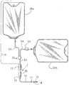
도1은 일단부에서의 유체 공급원 및 배출 백(bag) 시스템과, 타단부에서의 환자 내로 삽입될 카테테르 사이에서 분리된 상태에 있는 본 발명의 커넥터의 실시예의 전체적인 도면을 도시한다.BRIEF DESCRIPTION OF THE DRAWINGS Figure 1 shows an overall view of an embodiment of a connector of the present invention in a separate state between a fluid source and an exhaust bag system at one end and a catheter to be inserted into the patient at the other end.
도2는 분리 위치에서의 본 발명의 커넥터의 요소들의 실시예의 분해 사시도를 도시한다.Figure 2 shows an exploded perspective view of an embodiment of the elements of the connector of the present invention in a separate position.
도3은 연결 위치에서의 본 발명의 커넥터의 실시예의 사시도를 도시한다.Figure 3 shows a perspective view of an embodiment of the connector of the present invention in a connected position.
도4는 분리 위치에서의 본 발명의 커넥터의 덮개 로크 요소의 실시예의 부분 절결 단면도와 키이 요소의 실시예의 단면도를 도시한다.Fig. 4 shows a partial cut away sectional view of an embodiment of a cover lock element of the connector of the invention in a separate position and a cross-sectional view of an embodiment of the key element.
도5 내지 도7은 키이 요소와 덮개 로크 요소의 연속적인 연결 단계 및 관계를 도시하는 커넥터 조립체의 일부분의 실시예의 상세도를 도시한다.5 to 7 show a detailed view of an embodiment of a portion of a connector assembly showing the successive connection steps and relationship of a key element and a cover lock element.
도8은 연결 위치에서의 본 발명의 커넥터 조립체의 실시예의 부분 절결 단면도를 도시한다.Figure 8 shows a partially cutaway cross-sectional view of an embodiment of a connector assembly of the present invention in a connected position.
<현재의 양호한 실시예의 상세한 설명>DETAILED DESCRIPTION OF THE PREFERRED EMBODIMENTS [
본 발명은 소정 길이의 튜빙들을 선택적으로 연결 및 분리하기 위하여 소정길이의 2개의 튜빙 또는 다른 도관들 사이에서 커넥터를 제공한다. 연결될 때, 유체 공급원과 환자 사이에 유체 연통이 제공된다. 그러나, 커넥터와 연결된 폐색기를 사용하여 연결된 때, 유체는 유동이 폐색될 수 있다.The present invention provides a connector between two tubing or other conduits of a predetermined length to selectively connect and disconnect tubing of a predetermined length. When connected, fluid communication is provided between the fluid source and the patient. However, when connected using a plugger connected to the connector, the fluid may be occluded in the flow.
커넥터는 특히 의료 분야의 과정에서의 사용을 위해, 구체적으로는 투석 과정을 위해 설계되었지만, 커넥터는 다른 분야 및 다른 적용에 대해서도 사용될 수 있음을 알아야 한다.It should be understood that the connector is specifically designed for use in the medical field, particularly for the dialysis process, but the connector can be used for other applications and for other applications.
이제, 도면을 참조하면, 도1은 본 발명의 커넥터를 채용한 시스템의 전제적인 도면을 도시한다. 커넥터는 대체로 참조 부호 1로 나타나 있으며, 덮개 로크 요소(10) 및 키이 요소(12)를 포함한다. 도1에 도시된 바와 같이, 본 발명의 양호한실시예에서, 덮개 로크 요소(10)는 도관(14)에 연결된다. 사용시, 도관(14)은 카테테르(15)를 통해 환자에 부착될 수 있다. 도관(14)은 일단부에서 비틂 클램프(16)를, 타단부에서 카테테르 커넥터(17)를 구비한다. 카테테르(15)는 양호한 실시예에서 티타늄 어댑터(18)를 통해 카테테르 커넥터(17)에 연결될 수 있다.Referring now to the drawings, Fig. 1 shows an overall view of a system employing the connector of the present invention. The connector is generally indicated by
한편, 키이 요소(12)는 양호한 실시예에서 참조 부호 19로 나타낸 Y-세트에 연결될 수 있다. Y-세트(19)는 2개의 가요성 용기(20a, 20b)를 포함한다. 통상적으로, 복막 투석에 대해서는, 예컨대 가요성 용기들 중 하나인 가요성 용기(20a)는 투석물로 충전되고, 다른 가요성 용기(20b)는 비어 있어 배출 백으로서 사용될 준비가 된다. 본 발명의 커넥터(1)는 예컨대 복막 투석 및 CAPD에서 용이하게 사용될 수 있다. 물론, 커넥터의 다른 용도도 가능하다.On the other hand, the
양호한 실시예에서, 충전 라인(23)은 가요성 용기(20a)에 연결되고, 배출 라인(24)은 가요성 용기(20b)에 연결된다. 충전 라인(23) 및 배출 라인(24) 모두의 대향 단부들은 Y-연결부(21)에 각각 연결된다. 따라서, 가요성 용기(20a, 20b)는 Y-세트(19)의 일부를 형성하는 Y-연결부(21) 및 소정 길이의 도관(22)을 통해 키이요소에 부착된다.In a preferred embodiment, the filling
클램프(25)는 투석물의 유동을 요구되는 대로 제어하기 위하여 충전 라인(23)의 길이를 따라 임의의 지점에 마련될 수 있다. 또한, 클램프(25)는 필요하다면 복막 투석 동안에 배출 라인(24)에 연결될 수도 있다. 다른 실시예에서, 커넥터(1)의 덮개 로크 요소(10)는 유체 유동을 폐색하도록 덮개 로크 요소에 연결된 비틂 클램프(16)를 가질 수 있다.The
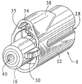
이제, 도2, 도3 및 도4를 참조하면, 커넥터(1)가 도시되어 있다. 예컨대, 도2는 연결 전의 덮개 로크 요소(10) 및 키이 요소(12)의 사시도를 도시한다. 덮개 로크 요소(10)는 키이 요소(12)의 개구 내에서 활주 결합으로 끼워 맞춤되도록 설계된 외부 치수를 갖는다. 더욱이, 덮개 로크 요소(10)의 외부는 덮개 로크 요소(10)의 단 하나의 방향 배치만이 키이 요소(12)의 개구(26) 내에 수용될 수 있도록 설계된다.Referring now to Figures 2, 3 and 4, the
이를 위해, 종방향 안내홈(27)이 덮개 로크 요소(10)의 대향 측면들에 형성된다. 안내홈(27)은 키이 요소(12)에 형성된 관련 안내 레일(28)과 협동 결합하여, 키이 요소(12)의 개구(26) 내에서 덮개 로크 요소(10)를 엄밀하게 안내하고 정렬시키도록 한다. 따라서, 협동하는 안내홈(27) 및 안내 레일(28)은 커넥터(1)에 대하여 단 하나의 허용 가능한 작동 방향 배치만을 허용한다.To this end, a
실시예에서, 덮개 로크 요소(10)는 도관(14)을 중심으로 축중심 회전할 수 있는 비틂 클램프(16)를 포함한다. 도2에 도시된 위치에서, 도관(14)(도1 참조)은 비틂 클램프(16) 내부에서 (도시되지 않은) 한 쌍의 작동기에 의해 밀착되어 사이에 끼인다. 탭(30)이 비틂 클램프(16) 상에 마련되어 사용자가 비틂 클램프(16)를 돌릴 때 조력할 뿐만 아니라 비틂 클램프(16)의 로킹 조건 또는 언로킹 조건의 가시적인 표시를 제공하도록 한다.In an embodiment, the
또한, 도2는 덮개 로크 요소(10)의 여러 특징부들을 도시한다. 예컨대, 일체로 형성된 정지부(32)(도4 참조)와 이들 사이에 있는 채널(33)을 갖는 한 쌍의 가요성 아암(31)이 도시되어 있다. 커넥터(1)의 요소(10, 12)의 연결 동안에아암(31)의 이동을 허용하는 측면 채널(36)이 또한 마련된다.Figure 2 also shows various features of the
이제, 도2에 도시된 커넥터(1)의 키이 요소(12)를 참조하면, 키이 요소(12)는 경사진 전방 단부면(35)을 갖는 가요성 종방향 키이(34)를 포함한다. 또한, 키이 요소(12)는 본 발명의 커넥터(1)의 연결 중에, 특히 (도6에 도시된 바와 같은) 분리 중에, 가요성 종방향 키이(34)의 이동을 허용하도록 돔(dome, 38)을 갖는다.Now referring to the
도3은 연결 위치에서의 본 발명의 커넥터(1)를 도시한다. 또한, 비틂 클램프(16) 상의 탭(30)은 도2에 도시된 위치로부터 90°회전된 것으로 도시되어 있다. 이는 사용자에게 커넥터(1)가 비틂 클램프(16)의 포트(40)에 의해 커넥터를 통해 유체 유동을 허용하는 상태에 있음을 나타낸다.Figure 3 shows the
이제, 도4를 참조하면, 단면으로 도시된 키이 요소(12)는 개구(26) 내에서 연장되는 종방향 키이(34)와, 개구(26) 내에서 종방향 키이(34)에 대해 대체로 평행하게 연장되는 관형 부재(44)를 갖는 것으로 도시되어 있다.4, a
또한, 도4에 도시된 덮개 로크 요소(10)는 액슬(axle, 52)을 중심으로 회전가능한 로킹 힌지식 도어(50)를 포함한다. 액슬(52)은 도4에서 로킹된 폐쇄 위치에서 도시된 도어(50)가 도8에 도시된 개방 위치로 약 90°회전되게 한다.The
게다가, 관형 부재(44)는 예컨대, 도관(22)의 연결을 허용하도록 키이 요소(12)의 외측으로 연장되는 니플(nipple, 46)을 구비한다. 종방향 키이(34)는 키이 요소(12)의 덮개 로크 요소(10)에의 연결 중에 후술되는 바와 같이 액슬(52)을 중심으로 도어(50)를 회전시킨다.The
도4를 계속 참조하면, 도어(50)는 본 발명의 실시예에서 관형 채널(58)의 표면(56)에 대하여 시일(seal)을 제공하도록 밀봉면(54)을 갖는다. 양호하게는, 관형 채널(58)은 예컨대 도관(14)을 단단히 연결하도록 미늘 형성 니플(barbed nipple, 60)을 대향 단부에서 포함한다. 또한, 도어(50)는 내부벽(63)을 밀봉하도록 O-링(62)을 제공함으로써 관형 채널(58)을 밀봉한다. 또한, 덮개 로크 요소(10)는 비틂 클램프(16)에 중간 연결된 어댑터(64)를 포함한다.4, the
이제, 도4 및 도8을 참조하면, 커넥터(1)는 덮개 로크 요소(10)를 키이 요소(12)에 연결하기 직전에서(도4) 그리고 이들 사이에 연결된 후에서(도8) 도시되어 있다. 덮개 로크 요소(10)와 키이 요소(12)의 연결 및 분리 사이의 식별은 도어(50)의 위치에 의해 가장 명확하게 된다.4 and 8, the
도4에 도시된 폐쇄 위치에서, 도어(50)는 덮개 로크 요소(10)의 단부면에 대체로 평행하며, 도어(50)가 90°회전된 후에 도8에 도시된 바와 같이 관형 부재(44)가 유체 연통 상태로 후속적으로 연결되는 관형 채널(58)을 밀봉식으로 덮는다. 덮개 로크 요소(10)와의 키이 요소(12)의 연결이 요구될 때, 키이 요소(12)는 덮개 로크 요소(10) 둘레에서 활주하여 결합되어, 정지부(32)에 의해 로킹된 도어(50)를 종방향 키이(34)가 언로킹하게 하고 도어(50)를 액슬(52)을 중심으로 회전하게 한다.4, the
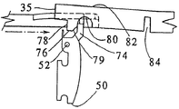
이제, 도5 내지 도7을 참조하여, 키이 요소(12)의 종방향 키이(34)를 사용함으로써 덮개 로크 요소(10)의 도어(50)를 개방하는 데 관여되는 단계의 설명이 이어진다. 특히 도5를 참조하면, 로킹되어 폐쇄된 도어(50)는 액슬(52)을 중심으로 회전 가능하다. 로킹되어 폐쇄된 도어(50)는 종방향 키이(34)가 도어(50)를 개방하기 위해 사용될 때까지 도어(50)를 로킹 위치에서 유지하도록 정지부(32)에 대하여 맞닿는 로킹 탭(74)을 구비한다.5 to 7, a description follows of the steps involved in opening the
또한, 도5에 도시된 바와 같이 종방향 키이(34)는 정면(78)을 갖는 개방 탭(76)을 구비한다. 또한, 종방향 키이(34)는 커넥터(1)의 분리 중에 개방 탭(76)의 간극을 허용하도록 만입 리세스(80)로 안내하는 경사면(79)을 구비한다. 또한, 종방향 키이(34)는 상부면(82)과, 종방향 키이(34)가 도6에 도시된 화살표 x로 나타낸 방향으로 후퇴될 때 종방향 키이(34)에 보다 큰 가요성을 제공하도록 굴곡 노치(84)를 구비한다. 도6은 커넥터(1)가 어떻게 분리되는가를 도시한다. 종방향 키이(34)는 덮개(50)의 로킹 탭(74)이 만입 리세스(80) 내에 위치될 때까지 화살표 x의 방향으로 후퇴된다. 종방향 키이(34)가 더욱 후퇴될 때, 경사면(79)은 로킹 탭(74)과 충돌한다. 따라서, 종방향 키이(34)의 계속된 후퇴는 로킹 탭(74)의 상부위에서 경사면(79)을 잡아당긴다. 그러나, 이러한 작용을 일으키기 위하여, 종방향 키이(34)는 가요성이 있어야만 하며, 따라서 굴곡 노치(84)는 경사면(79)이 로킹 탭(74) 위로 오름에 따라 종방향 키이(34)가 상승하도록 제공된다. 또한, 도8에 도시된 돔(38)은 종방향 키이가 후퇴 중에 상승함에 따라 종방향 키이(34)에 대하여 간극을 제공한다. 게다가, 연결 중에, 종방향 키이(34)의 굴곡량이 더 적게 될 수 있다.5, the
도5를 참조하여 더욱 설명되는 것으로서, 종방향 키이(34)의 경사 단부면(35)은 덮개 로크 요소(10)의 아암(31)과 접촉하여 아암을 벌린다. 종방향 키이(34)는 가요성이 있지만, 종방향 키이는 압축시 아암(31)을 벌려 채널(33)을넓히도록 할 때 충분한 강성을 갖는다. 도7의 평면도로부터 도시된 바와 같이, 종방향 키이(34)는 종방향 키이가 화살표 A로 나타낸 외측 방향으로 아암(31)을 충분히 벌려 개방할 때까지 채널(33)을 통해 진행한다. 그리고 나서, 종방향 키이(34)의 개방 탭(76)의 정면은 덮개(50)의 로킹 탭(74)을 넓혀진 채널(33)을 통해 가압한다. 따라서, 종방향 키이(34)는 로킹 탭(74)이 아암(31) 내에 형성된 정지부(32)를 제거할 수 있도록 아암(31)을 충분히 개방한다. 그리고 나서, 이제 언로킹된 덮개(50)의 로킹 탭(74)은 벌려진 아암(31)을 통과할 수 있다.5, the inclined end face 35 of the longitudinal key 34 contacts the
키이 요소(12)가 도8에 도시된 바와 같이 덮개 로크 요소(10)에 연결된 때, 도어(50)는 덮개 로크 요소의 단부면에 대하여 직각으로 배치된다. 개구(26) 및 돔(38)은 도어(50)가 도8에 도시된 바와 같이 선회하게 하는 간극을 허용하도록 구성 및 배열된다. 키이 요소(12)의 덮개 로크 요소(10)에 대한 연결 후에, Y-세트(19)와 환자 사이의 유체 연통이 성취될 수 있다.When the
전술한 바와 같이, 덮개 로크 요소(10)는 덮개 로크 요소(10)와 환자 사이에서 도관(14)의 길이에 대해 평행한 축을 중심으로 부분적으로 회전 가능한 비틂 클램프(16)도 포함한다. 전술된 바와 같이, 비틂 클램프(16) 내부에 (도시되지 않은) 작동기 쌍이 있다. 비틂 클램프(16)는 축을 중심으로 회전함으로써, 작동기의 위치를 도관 압축 위치 및 유동 위치로 편향시킨다.The
커넥터(1)의 작동은 덮개 로크 요소(10)의 키이 요소(12)로의 삽입을 포함하며, 종방향 키이(34)는 아암(31)을 벌려, 도어(50)를 로킹하는 정지부(32)에 대하여 작용하도록 함으로써 도어(50)가 개방되게 한다.The operation of the
따라서, 관형 부재(44)는 덮개 로크 요소(10)의 관형 채널(58)과 협동하여 결합한다. 관형 부재(44)는 덮개 로크 요소(10)의 개구(도8 참조)에 인접하여 안내되어, 키이 요소(12) 및 덮개 로크 요소(10)를 통한 유체 연통을 제공한다.Thus, the
도어(50)의 언로킹되어 개방되는 것에 이어서 덮개 로크 요소(10) 및 키이 요소(12)가 더욱 결합하게 됨에 따라, 키이 요소(12)의 관형 부재(44)는 덮개 로크 요소(10)의 관형 채널(58)에 밀봉 결합된다. 이를 위해, 관형 부재(44)는 이들의 밀봉 결합에서 있어서 조력하는 도입부를 위한 테이퍼(86)를 구비할 수 있다. 다른 실시예에서, 관형 부재(44)는 이들 사이에서 밀봉을 유지하도록 O-링(88)을 포함할 수 있다.The
본 명세서에서 설명된 현재의 양호한 실시예들에 대해 여러 변경 및 수정은 당해 기술 분야의 숙련자에게 명백하다는 것을 알아야 한다. 이러한 변경 및 수정은 본 발명의 정신 및 범주로부터 벗어나지 않고 수반하는 이점을 감소시킴이 없이 이루어질 수 있다. 따라서, 첨부된 청구의 범위는 이러한 변경 및 수정을 포함하려는 것이다.It should be noted that various changes and modifications to the presently preferred embodiments described herein will be apparent to those skilled in the art. Such changes and modifications may be made without departing from the spirit and scope of the invention and without diminishing its attendant advantages. Accordingly, the appended claims are intended to cover such modifications and changes.
Claims (25)
Applications Claiming Priority (2)
| Application Number | Priority Date | Filing Date | Title |
|---|---|---|---|
| US08/510,890 | 1995-08-03 | ||
| US08/510,890 US5582600A (en) | 1995-08-03 | 1995-08-03 | Transfer set connector with a locking lid and a method of using the same |
Publications (2)
| Publication Number | Publication Date |
|---|---|
| KR970706036A KR970706036A (en) | 1997-11-03 |
| KR100400144B1 true KR100400144B1 (en) | 2003-12-24 |
Family
ID=24032611
Family Applications (1)
| Application Number | Title | Priority Date | Filing Date |
|---|---|---|---|
| KR1019970702149A KR100400144B1 (en) | 1995-08-03 | 1996-07-17 | TRANSMISSION SET CONNECTOR WITH LOCKING COVER AND METHOD OF USING THE SAME |
Country Status (15)
| Country | Link |
|---|---|
| US (1) | US5582600A (en) |
| EP (1) | EP0796123B1 (en) |
| JP (2) | JP3830523B2 (en) |
| KR (1) | KR100400144B1 (en) |
| CN (1) | CN1137737C (en) |
| AT (1) | ATE226463T1 (en) |
| AU (1) | AU707044B2 (en) |
| BR (1) | BR9606565A (en) |
| CA (1) | CA2197549A1 (en) |
| DE (1) | DE69624464T2 (en) |
| DK (1) | DK0796123T3 (en) |
| ES (1) | ES2185788T3 (en) |
| MX (1) | MX9701809A (en) |
| TW (1) | TW305764B (en) |
| WO (1) | WO1997005921A1 (en) |
Families Citing this family (24)
| Publication number | Priority date | Publication date | Assignee | Title |
|---|---|---|---|---|
| US6228255B1 (en) * | 1998-07-24 | 2001-05-08 | Dialysis Systems, Inc. | Portable water treatment facility |
| US6077259A (en) * | 1998-09-30 | 2000-06-20 | Becton, Dickinson And Company | Contamination resistant connector |
| DE60016688T2 (en) * | 1999-10-06 | 2005-05-19 | Nortel Networks Ltd., St. Laurent | Coupling field for optical signals |
| US6251279B1 (en) | 1999-12-09 | 2001-06-26 | Dialysis Systems, Inc. | Heat disinfection of a water supply |
| DE10011724C1 (en) * | 2000-03-10 | 2001-04-26 | Fresenius Medical Care De Gmbh | Connector for sterile packed fluid systems, such as kidney dialysis fluid flow system, comprises connections at both ends, each having inner slides with limit stops |
| DE10352859B3 (en) * | 2003-11-10 | 2005-06-02 | Fresenius Medical Care Deutschland Gmbh | Connector for dialyzer port |
| JPWO2006068211A1 (en) * | 2004-12-22 | 2008-06-12 | テルモ株式会社 | Connectors, tube assemblies, infusion tube sets and medical containers |
| JP4857853B2 (en) * | 2006-03-28 | 2012-01-18 | ニプロ株式会社 | Transfer tool kit and adapter member |
| WO2008069052A1 (en) * | 2006-12-07 | 2008-06-12 | Terumo Kabushiki Kaisha | Connector assembly and infusion set |
| US8882700B2 (en) | 2008-05-02 | 2014-11-11 | Baxter International Inc. | Smart patient transfer set for peritoneal dialysis |
| US9348975B2 (en) | 2008-05-02 | 2016-05-24 | Baxter International Inc. | Optimizing therapy outcomes for peritoneal dialysis |
| US8377012B2 (en) | 2009-01-30 | 2013-02-19 | Baxter International Inc. | Transfer sets for therapy optimization |
| US8753515B2 (en) | 2009-12-05 | 2014-06-17 | Home Dialysis Plus, Ltd. | Dialysis system with ultrafiltration control |
| US8795250B2 (en) | 2010-03-30 | 2014-08-05 | First Quality Baby Products, Llc | Absorbent article having leg cuffs |
| US8501009B2 (en) | 2010-06-07 | 2013-08-06 | State Of Oregon Acting By And Through The State Board Of Higher Education On Behalf Of Oregon State University | Fluid purification system |
| US20130079730A1 (en) * | 2010-06-08 | 2013-03-28 | Theodore J. Mosler | Connector assembly |
| US8777931B2 (en) | 2011-08-19 | 2014-07-15 | Alcon Research, Ltd. | Retractable luer lock fittings |
| WO2013052680A2 (en) | 2011-10-07 | 2013-04-11 | Home Dialysis Plus, Ltd. | Heat exchange fluid purification for dialysis system |
| EP2837404B1 (en) * | 2012-04-13 | 2022-10-26 | JMS Co., Ltd. | Male connector equipped with lock mechanism |
| US20150238746A1 (en) * | 2014-02-26 | 2015-08-27 | Baxter Healthcare Sa | Frangible connector closure for tubular connector |
| WO2015168280A1 (en) | 2014-04-29 | 2015-11-05 | Outset Medical, Inc. | Dialysis system and methods |
| JP6825210B2 (en) * | 2016-03-02 | 2021-02-03 | 株式会社ジェイ・エム・エス | Puncture needle connector and connecting tube |
| EP3500317B1 (en) | 2016-08-19 | 2022-02-23 | Outset Medical, Inc. | Peritoneal dialysis system and methods |
| SE545392C2 (en) * | 2021-12-06 | 2023-07-25 | Tada Group Ab | Coupling system for fluid transfer |
Family Cites Families (15)
| Publication number | Priority date | Publication date | Assignee | Title |
|---|---|---|---|---|
| US4541658A (en) * | 1982-03-22 | 1985-09-17 | Proprietary Technology, Inc. | Swivelable quick connector assembly |
| US5330450A (en) * | 1983-01-24 | 1994-07-19 | Icu Medical, Inc. | Medical connector |
| US5344414A (en) * | 1983-01-24 | 1994-09-06 | Icu Medical Inc. | Medical connector |
| US4752292A (en) * | 1983-01-24 | 1988-06-21 | Icu Medical, Inc. | Medical connector |
| US5281206A (en) * | 1983-01-24 | 1994-01-25 | Icu Medical, Inc. | Needle connector with rotatable collar |
| CA1272655A (en) * | 1985-07-31 | 1990-08-14 | Yukihiro Kawano | Connector for plasmapheresis bag |
| US4645494A (en) * | 1985-10-22 | 1987-02-24 | Renal Systems, Inc. | Peritoneal device system |
| DE3605016A1 (en) * | 1986-02-18 | 1987-08-20 | Voss Armaturen | CONNECTING DEVICE WITH ANTI-TWISTING |
| CH672363A5 (en) * | 1986-09-29 | 1989-11-15 | Contempo Products | |
| US4895570A (en) * | 1987-06-05 | 1990-01-23 | Abbott Laboratories | Locking port shroud for peritoneal dialysis tubing connector |
| CA2001732A1 (en) * | 1988-10-31 | 1990-04-30 | Lawrence A. Lynn | Intravenous line coupling device |
| US4950260A (en) * | 1989-11-02 | 1990-08-21 | Safetyject | Medical connector |
| EP0453264A1 (en) * | 1990-04-17 | 1991-10-23 | Lynn, Lawrence A. | Medical connector |
| US5195957A (en) * | 1991-02-01 | 1993-03-23 | Tollini Dennis R | Sterilant cartridge-cap and associated connection |
| US5356396A (en) * | 1992-09-29 | 1994-10-18 | Medical Associates Network Inc. | Infusion apparatus |
-
1995
- 1995-08-03 US US08/510,890 patent/US5582600A/en not_active Expired - Lifetime
-
1996
- 1996-07-17 BR BR9606565A patent/BR9606565A/en not_active IP Right Cessation
- 1996-07-17 CN CNB961908599A patent/CN1137737C/en not_active Expired - Lifetime
- 1996-07-17 MX MX9701809A patent/MX9701809A/en unknown
- 1996-07-17 DK DK96925337T patent/DK0796123T3/en active
- 1996-07-17 KR KR1019970702149A patent/KR100400144B1/en not_active IP Right Cessation
- 1996-07-17 ES ES96925337T patent/ES2185788T3/en not_active Expired - Lifetime
- 1996-07-17 AT AT96925337T patent/ATE226463T1/en not_active IP Right Cessation
- 1996-07-17 AU AU65471/96A patent/AU707044B2/en not_active Ceased
- 1996-07-17 DE DE69624464T patent/DE69624464T2/en not_active Expired - Lifetime
- 1996-07-17 EP EP96925337A patent/EP0796123B1/en not_active Expired - Lifetime
- 1996-07-17 JP JP50844397A patent/JP3830523B2/en not_active Expired - Lifetime
- 1996-07-17 CA CA002197549A patent/CA2197549A1/en not_active Abandoned
- 1996-07-17 WO PCT/US1996/011811 patent/WO1997005921A1/en active IP Right Grant
- 1996-08-03 TW TW085109478A patent/TW305764B/zh not_active IP Right Cessation
-
2006
- 2006-05-11 JP JP2006133140A patent/JP2006255435A/en not_active Withdrawn
Also Published As
| Publication number | Publication date |
|---|---|
| CN1137737C (en) | 2004-02-11 |
| JP3830523B2 (en) | 2006-10-04 |
| WO1997005921A1 (en) | 1997-02-20 |
| JP2006255435A (en) | 2006-09-28 |
| CA2197549A1 (en) | 1997-02-04 |
| AU707044B2 (en) | 1999-07-01 |
| DK0796123T3 (en) | 2003-02-17 |
| TW305764B (en) | 1997-05-21 |
| EP0796123B1 (en) | 2002-10-23 |
| EP0796123A1 (en) | 1997-09-24 |
| JPH10507396A (en) | 1998-07-21 |
| US5582600A (en) | 1996-12-10 |
| BR9606565A (en) | 1997-12-30 |
| DE69624464T2 (en) | 2003-06-26 |
| AU6547196A (en) | 1997-03-05 |
| ES2185788T3 (en) | 2003-05-01 |
| KR970706036A (en) | 1997-11-03 |
| ATE226463T1 (en) | 2002-11-15 |
| CN1161004A (en) | 1997-10-01 |
| MX9701809A (en) | 1998-04-30 |
| DE69624464D1 (en) | 2002-11-28 |
Similar Documents
| Publication | Publication Date | Title |
|---|---|---|
| KR100400144B1 (en) | TRANSMISSION SET CONNECTOR WITH LOCKING COVER AND METHOD OF USING THE SAME | |
| KR100356635B1 (en) | Medical Tubular Connectors | |
| EP0675744B1 (en) | A self-valving connecting device and its use | |
| US4366816A (en) | Combination quick disconnect coupling and fluid cutoff valve | |
| EP0175428B1 (en) | Tube coupling member, especially for antimicrobial irradiation | |
| US4745950A (en) | Connector for peritoneal dialysis | |
| US4338933A (en) | Combination quick disconnect coupling and liquid cutoff valve | |
| US5713850A (en) | Apparatus for controlling a fluid flow | |
| EP1547645B1 (en) | Medical tube connector device | |
| US6814726B1 (en) | Connector element with a sealing part | |
| US4560382A (en) | Medical container | |
| EP1727573B1 (en) | Apparatus for applying and removing closing means from an end portion of a tubular element for peritoneal dialysis | |
| AU7381898A (en) | Connector assemblies, fluid systems, and methods for making a connection | |
| EP0401609A1 (en) | Medical container replacing method | |
| EP0413680B1 (en) | Connection preferably for medical use | |
| MXPA96001469A (en) | Connector for med tube | |
| EP2121115B1 (en) | A medical product, and a method of sterilizing a medical product |
Legal Events
| Date | Code | Title | Description |
|---|---|---|---|
| A201 | Request for examination | ||
| E701 | Decision to grant or registration of patent right | ||
| GRNT | Written decision to grant | ||
| FPAY | Annual fee payment |
Payment date: 20090917 Year of fee payment: 7 |
|
| LAPS | Lapse due to unpaid annual fee |