EP2837404B1 - Male connector equipped with lock mechanism - Google Patents
Male connector equipped with lock mechanism Download PDFInfo
- Publication number
- EP2837404B1 EP2837404B1 EP13775776.1A EP13775776A EP2837404B1 EP 2837404 B1 EP2837404 B1 EP 2837404B1 EP 13775776 A EP13775776 A EP 13775776A EP 2837404 B1 EP2837404 B1 EP 2837404B1
- Authority
- EP
- European Patent Office
- Prior art keywords
- male
- female connector
- hood
- connector
- claw
- Prior art date
- Legal status (The legal status is an assumption and is not a legal conclusion. Google has not performed a legal analysis and makes no representation as to the accuracy of the status listed.)
- Active
Links
- 210000000078 claw Anatomy 0.000 claims description 68
- 238000006073 displacement reaction Methods 0.000 claims description 13
- 238000000926 separation method Methods 0.000 claims description 11
- 238000004891 communication Methods 0.000 claims description 8
- 238000003780 insertion Methods 0.000 claims description 7
- 230000037431 insertion Effects 0.000 claims description 7
- 239000007788 liquid Substances 0.000 description 11
- 239000003814 drug Substances 0.000 description 10
- 229940079593 drug Drugs 0.000 description 10
- 239000000243 solution Substances 0.000 description 7
- 239000008280 blood Substances 0.000 description 6
- 210000004369 blood Anatomy 0.000 description 6
- 238000000034 method Methods 0.000 description 6
- 239000000470 constituent Substances 0.000 description 3
- 239000000463 material Substances 0.000 description 3
- 239000002246 antineoplastic agent Substances 0.000 description 2
- 229940041181 antineoplastic drug Drugs 0.000 description 2
- 238000005452 bending Methods 0.000 description 2
- 230000005489 elastic deformation Effects 0.000 description 2
- 239000013013 elastic material Substances 0.000 description 2
- 238000005192 partition Methods 0.000 description 2
- 229930182556 Polyacetal Natural products 0.000 description 1
- 239000004952 Polyamide Substances 0.000 description 1
- 239000004743 Polypropylene Substances 0.000 description 1
- 239000004793 Polystyrene Substances 0.000 description 1
- 238000013459 approach Methods 0.000 description 1
- 230000017531 blood circulation Effects 0.000 description 1
- 230000006835 compression Effects 0.000 description 1
- 238000007906 compression Methods 0.000 description 1
- 230000007423 decrease Effects 0.000 description 1
- 230000000694 effects Effects 0.000 description 1
- 230000002349 favourable effect Effects 0.000 description 1
- 239000012530 fluid Substances 0.000 description 1
- 238000001802 infusion Methods 0.000 description 1
- 238000002347 injection Methods 0.000 description 1
- 239000007924 injection Substances 0.000 description 1
- 239000002184 metal Substances 0.000 description 1
- 238000000465 moulding Methods 0.000 description 1
- 244000052769 pathogen Species 0.000 description 1
- 230000001717 pathogenic effect Effects 0.000 description 1
- 229920002647 polyamide Polymers 0.000 description 1
- 229920000515 polycarbonate Polymers 0.000 description 1
- 239000004417 polycarbonate Substances 0.000 description 1
- 229920006324 polyoxymethylene Polymers 0.000 description 1
- -1 polypropylene Polymers 0.000 description 1
- 229920001155 polypropylene Polymers 0.000 description 1
- 229920002223 polystyrene Polymers 0.000 description 1
- 229920000915 polyvinyl chloride Polymers 0.000 description 1
- 239000004800 polyvinyl chloride Substances 0.000 description 1
- 239000011347 resin Substances 0.000 description 1
- 229920005989 resin Polymers 0.000 description 1
- 239000000126 substance Substances 0.000 description 1
- 238000001356 surgical procedure Methods 0.000 description 1
Images


Classifications
-
- A—HUMAN NECESSITIES
- A61—MEDICAL OR VETERINARY SCIENCE; HYGIENE
- A61M—DEVICES FOR INTRODUCING MEDIA INTO, OR ONTO, THE BODY; DEVICES FOR TRANSDUCING BODY MEDIA OR FOR TAKING MEDIA FROM THE BODY; DEVICES FOR PRODUCING OR ENDING SLEEP OR STUPOR
- A61M39/00—Tubes, tube connectors, tube couplings, valves, access sites or the like, specially adapted for medical use
- A61M39/02—Access sites
- A61M39/04—Access sites having pierceable self-sealing members
- A61M39/045—Access sites having pierceable self-sealing members pre-slit to be pierced by blunt instrument
-
- A—HUMAN NECESSITIES
- A61—MEDICAL OR VETERINARY SCIENCE; HYGIENE
- A61M—DEVICES FOR INTRODUCING MEDIA INTO, OR ONTO, THE BODY; DEVICES FOR TRANSDUCING BODY MEDIA OR FOR TAKING MEDIA FROM THE BODY; DEVICES FOR PRODUCING OR ENDING SLEEP OR STUPOR
- A61M39/00—Tubes, tube connectors, tube couplings, valves, access sites or the like, specially adapted for medical use
- A61M39/10—Tube connectors; Tube couplings
- A61M39/1011—Locking means for securing connection; Additional tamper safeties
-
- A—HUMAN NECESSITIES
- A61—MEDICAL OR VETERINARY SCIENCE; HYGIENE
- A61M—DEVICES FOR INTRODUCING MEDIA INTO, OR ONTO, THE BODY; DEVICES FOR TRANSDUCING BODY MEDIA OR FOR TAKING MEDIA FROM THE BODY; DEVICES FOR PRODUCING OR ENDING SLEEP OR STUPOR
- A61M39/00—Tubes, tube connectors, tube couplings, valves, access sites or the like, specially adapted for medical use
- A61M39/10—Tube connectors; Tube couplings
- A61M39/12—Tube connectors; Tube couplings for joining a flexible tube to a rigid attachment
-
- A—HUMAN NECESSITIES
- A61—MEDICAL OR VETERINARY SCIENCE; HYGIENE
- A61M—DEVICES FOR INTRODUCING MEDIA INTO, OR ONTO, THE BODY; DEVICES FOR TRANSDUCING BODY MEDIA OR FOR TAKING MEDIA FROM THE BODY; DEVICES FOR PRODUCING OR ENDING SLEEP OR STUPOR
- A61M39/00—Tubes, tube connectors, tube couplings, valves, access sites or the like, specially adapted for medical use
- A61M39/10—Tube connectors; Tube couplings
- A61M2039/1016—Unlocking means providing a secure or comfortable disconnection
-
- A—HUMAN NECESSITIES
- A61—MEDICAL OR VETERINARY SCIENCE; HYGIENE
- A61M—DEVICES FOR INTRODUCING MEDIA INTO, OR ONTO, THE BODY; DEVICES FOR TRANSDUCING BODY MEDIA OR FOR TAKING MEDIA FROM THE BODY; DEVICES FOR PRODUCING OR ENDING SLEEP OR STUPOR
- A61M39/00—Tubes, tube connectors, tube couplings, valves, access sites or the like, specially adapted for medical use
- A61M39/10—Tube connectors; Tube couplings
- A61M2039/1027—Quick-acting type connectors
Definitions
- the present invention relates to a male connector that includes a lock mechanism for maintaining a state of connection to a female connector.
- Transport lines generally are formed by connecting containers, various types of instruments, feed tubes, and the like.
- a drug solution bag container
- a male connector and a female connector are used to interconnect different members detachably.
- a female connector used in this application is a needleless port that has a disk-shaped partition wall member (hereinafter referred to as a "septum”) that is made of an elastic material such as rubber and has a linear slit (incision) formed in the central portion (e.g., see JP 3389983 B ).
- a tubular male luer male member
- the needleless port and the male luer can be put in communication with each other.
- the slit in the septum immediately closes when the male luer is withdrawn from the needleless port.
- the drug solution contains a drug designated as a dangerous drug, such as some anticancer drugs.
- blood contains a pathogen or the like. Accordingly, it is necessary to avoid a situation where a connected male connector and female connector unintentionally become separated, and as a result a liquid such as a drug solution or blood leaks out and comes into contact with the operator's finger or the like, or the operator inhales vapor from the liquid.
- a prior art male connector 900 with a lock mechanism has been previously proposed in which, as shown in FIGS. 9A and 9B , a male luer 910 is provided with a lock mechanism for maintaining a state in which the male luer 910 is connected to a needleless port (e.g., see JP 2004-483 A , WO 2010/061742 and WO 2010/061743 ).
- This prior art lock mechanism includes a pair of lock levers 930 arranged so as to be approximately parallel to the male luer 910 and sandwich the male luer 910.
- the lock levers 930 are connected to a base end portion 919 of the male luer 910 via support pieces 931 provided at an approximately central position in the lengthwise direction of the lock levers 930.
- a claw 934 that engages with the needleless port is formed on one end of each of the lock levers 930, on the surface on the side that opposes the male luer.
- the end portions of the lock levers 930 on the side not provided with the claws 934 are operation portions 935 for operating the lock levers.
- Numeral 920 indicates an approximately cylindrical hood that surrounds the male luer 910 and is fixed to the base end portion 919.
- the pair of lock levers 930 are arranged in notches provided in the hood 920.
- Numeral 915 indicates a tubular portion that is in communication with the male luer 910 and is for connection to a flexible tube (not shown).
- the prior art male luer 910 is inserted into a septum 951 of a needleless port 950, and the claws 934 provided on the tips of the pair of lock levers 930 are engaged with a step on the outer circumferential face of the needleless port 950. Accordingly, the state of connection of the needleless port 950 and the male luer 910 is locked. Even if the male connector 900 and the needleless port 950 are pulled away from each other, the male connector 900 and the needleless port 950 cannot be separated since the claws 934 of the lock levers 930 are engaged with the needleless port 950.
- the prior art male connector 900 and the needleless port 950 can be separated by applying force F1 to the operation portions 935 of the pair of lock levers 930 in a direction in which they approach each other, so as to displace the lock levers 930 and cancel the engagement between the claws 934 of the lock levers 930 and the needleless port 950.
- JP 2012034738 A discloses a removable adapter for a male luer assembly having engagement pawls, grip parts and an engagement structure.
- US 5582600 A discloses a connector assembly for fluid communication having a key component and a lid lock component, the lid lock component including a removably lockable lid.
- the locked state can be canceled by applying the pressing force F1 to the operation portions 935 of the lock levers 930. Accordingly, if an unintended external force is applied to the operation portions 935 of the lock levers 930, there is a possibility of the locked state becoming canceled.
- An object of the present invention is to provide a male connector with a lock mechanism that is highly safe and has a reduced possibility of the locked state being unintentionally canceled by external force.
- a male connector and a corresponding female connector comprising: a bar-shaped male member for insertion into the female connector; and a lock mechanism for maintaining a state in which the male member is inserted into the female connector, wherein the lock mechanism includes: a hood that is arranged so as to surround a periphery of the male member and is for insertion of the female connector; and characterised in that the lock mechanism includes: a single lock lever having a cantilever support structure capable of elastic displacement, wherein the lock lever includes: a claw for engaging with the female connector; and an operation portion for elastically displacing the lock lever in a direction of separation from the male member, wherein the claw and the operation portion are provided on a free end side of the lock lever, and in use, when the female connector is connected to the male connector, the claw engages with the female connector so that the male member is prevented from coming out of the female connector.
- the claw provided on the single lock lever can be engaged with the female connector inserted into the hood, thus making it possible to maintain the state in which the male member is connected to the female connector. Also, canceling the engagement between the claw and the female connector requires displacing the lock lever in the direction of moving away from the male member, and thus there is a low possibility of the locked state achieved by the lock mechanism being unintentionally canceled by external force. Accordingly, it is possible to provide a male connector with a lock mechanism that is highly safe.
- a male connector with a lock mechanism of the present invention includes a bar-shaped male member for insertion into a female connector, and a lock mechanism for maintaining a state in which the male member is inserted into the female connector.
- the lock mechanism includes a hood that is arranged so as to surround a periphery of the male member and is for insertion of the female connector, and a single lock lever having a cantilever support structure capable of elastic displacement.
- the lock lever includes a claw for engaging with the female connector, and an operation portion for elastically displacing the lock lever in a direction of separation from the male member. The claw and the operation portion are provided on a free end side of the lock lever.
- the above male connector with a lock mechanism of the present invention further includes a displacement limiting means that sets an upper limit of an elastic displacement amount of the lock lever. According to this, it is possible to prevent the lock lever from becoming plastically deformed or damaged due to an operator greatly displacing the lock lever more than necessary.
- an opening for allowing engagement of the claw to the female connector is formed in the hood.
- this preferable configuration is advantageous in preventing an operator from mistakenly touching the male member, in positioning the female connector using the hood, and in suppressing a reduction in the mechanical strength of the hood.
- the hood includes a bridge portion on a side on which the female connector is inserted relative to the opening, and the bridge portion connects portions of the hood that sandwich the opening in a circumferential direction. According to this, even if external force acts on the female connector in the state of being connected and locked to the male connector, it is possible to suppress inclination and movement of the female connector. As a result, it is possible to reduce the possibility of the locked state being unintentionally canceled and the hood becoming damaged.
- a channel is formed in the male member, and a lateral hole in communication with the channel is open at an outer circumferential face of the male member.
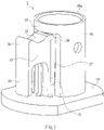
- FIG. 1 is a perspective view of a male connector with a lock mechanism (referred to hereinafter as simply "male connector") 1 according to an embodiment of the present invention.
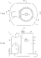
- FIG. 2A is a plan view of the male connector 1
- FIG. 2B is a side view of the male connector 1.
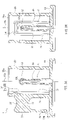
- FIG. 3A is a cross-sectional arrow view of the male connector 1 taken along a plane including a line 3A-3A in FIG. 2A
- FIG. 3B is a cross-sectional arrow view of the male connector 1 taken along a plane including a line 3B-3B in FIG. 2A .
- the male connector 1 of the present embodiment includes a bar-shaped male luer 10 as a male member.
- 10a indicates the central axis of the male luer 10.
- the lengthwise direction of the male luer 10 (direction parallel to the central axis 10a) will be referred to as the "up-down direction”, and the direction orthogonal to the lengthwise direction of the male luer 10 will be referred to as the "horizontal direction”.
- the side close to a base 19 will be referred to as the "lower side”
- the side far from it will be referred to as the "upper side” or the "tip side”.
- the "up-down direction” and the “horizontal direction” do not mean orientations during actual use of the male connector 1. Furthermore, the direction of a line orthogonal to the central axis 10a of the male luer 10 will be referred to as the "radial direction”, and the direction of rotation about the central axis 10a will be referred to as the "circumferential direction”.
- the male luer 10 is a bar-shaped member that protrudes from the base 19.
- the outer circumferential face (i.e., side face) of the male luer 10 is a tapered face such that the outer diameter slightly decreases with increasing distance from the base 19 in the present embodiment.
- the shape of the outer circumferential face of the male luer 10 is not limited to this, and any shape can be selected. For example, it may be a cylindrical face such that the outer diameter is constant in the up-down direction.
- a channel 11 is formed in the male luer 10 along the lengthwise direction thereof.
- the channel 11 is not open at a tip face 10t of the male luer 10.
- a lateral hole 12 that is in communication with the channel 11 is formed in the vicinity of the tip of the male luer 10.
- the lateral hole 12 passes through the male luer 10 in the radial direction, and is open at two locations on the outer circumferential face of the male luer 10. Note that the lateral hole 12 may be open at only one location on the outer circumferential face of the male luer 10 instead of passing completely through male luer 10.
- the configuration of the base 19 on the side opposite to the male luer 10 will not be described due to not being directly related to the present invention.
- the liquid channel 11 is open at the lower face of the base 19 in the present embodiment, the liquid channel 11 may be extended and put in communication with a desired channel.
- a hood 20 is provided upright on the base 19 on the same side as the male luer 10 so as to surround the male luer 10.
- the hood 20 is shaped as a hollow cylinder that is coaxial with the male luer 10, and the height (up-down direction dimension) of the hood 20 is greater than the height of the male luer 10.
- the inner circumferential face of the hood 20 (the face opposing the male luer 10) is a cylindrical face having an inner diameter approximately the same as or slightly greater than the outer diameter of a female connector to which the male connector 1 of the present embodiment is to be connected.
- An opening (through-hole) 21 is formed in the hood 20. The opening 21 extends from the base 19 to a position slightly higher than the male luer 10.
- the opening 21 does not extend to the upper end of the hood 20, and a bridge portion 22 provided above the opening 21 connects portions of the hood 20 on the two sides of the opening 21 in the circumferential direction.
- An upper edge 20a of the hood 20 has a circular shape in a plan view, and is continuous in the circumferential direction with the same height.
- a lock lever 30 is provided upright on the base 19 so as to oppose the male luer 10 via the opening 21 of the hood 20.
- the lock lever 30 includes an elastic portion 31 that extends perpendicularly from the base 19, a lock piece 33 provided on the upper end of the elastic portion 31, and a stopper 38 that extends from the lock piece 33 toward the base 19, and as shown in FIGS. 2B and 3A , the lock lever 30 is overall shaped as an upside "J" or an upside "U”.
- the elastic portion 31 is shaped as a thin plate that extends along a plane orthogonal to the radial direction of the male luer 10. As a result, the elastic portion 31 is capable of being displaced so as to elastically bend in a plane that includes the central axis 10a of the male luer 10.
- the lock piece 33 is an approximately quadrangular plate-shaped member that extends along the radial direction of the male luer 10.
- the face of the lock piece 33 on the side opposing the male luer 10 is on the same plane as the elastic portion 31, and a claw 34 that protrudes toward the male luer 10 is formed on the upper end of this face of the lock piece 33.
- the claw 34 includes an inclined face 34a and an engaging face 34b.
- the inclined face 34a is inclined so as to move away from the male luer 10 with increasing distance from the base 19.
- the engaging face 34b is arranged on the base 19 side relative to the inclined face 34a, and is a flat face that is approximately parallel to the horizontal direction.
- the apex portion of the claw 34 protrudes to a position on the male luer 10 side relative to the inner circumferential face of the hood 20.
- the upper face of the lock piece 33 is an operation portion 35 that is sunken so as to be shaped as an approximately cylindrical face.
- the operation portion 35 extends and protrudes outward along the radial direction from the outer circumferential face of the hood 20.
- the stopper 38 is elongated such that the face of the lock piece 33 on the side opposite to the male luer 10 extends toward the base 19. A lower end 38b of the stopper 38 and the base 19 are separated via a gap 39.
- the lock lever 30 has a cantilever support structure in which the lower end of the elastic portion 31 fixed to the base 19 is the fixed end, and the upper end side provided with the claw 34 and the operation portion 35 is the free end. If a finger is brought into contact with the operation portion 35, and force F in a direction of separation from the hood 20 is applied to the operation portion 35, the elastic portion 31 undergoes elastic bending deformation, and the lower end 38b of the stopper 38 comes into contact with the base 19 as shown in FIG. 4 . At this time, the claw 34 becomes displaced in a direction of separation from the male luer 10 approximately along the radial direction.
- the hood 20 and the lock lever 30 described above configure the lock mechanism of the male connector 1 of the present embodiment.
- the male luer 10, the base 19, the hood 20, and the lock lever 30 are made of a hard material.
- the male luer 10, the base 19, the hood 20, and the lock lever 30 can be created with a method such as integral molding, using a resin material such as polyacetal, polycarbonate, polystyrene, polyamide, polypropylene, or rigid polyvinyl chloride.
- FIG. 5 is a perspective view of the male connector 1 and a needleless port 100 serving as the female connector, immediately before connection.
- FIGS. 6A and 6B are cross-sectional views of the male connector 1 and the needleless port 100 immediately before connection. The cross-sections in FIGS. 6A and 6B are the same as the cross-sections in FIGS. 3A and 3B respectively.
- the needleless port 100 includes disk-shaped partition wall member (septum) 101 that is made of an elastic material such as rubber and is provided with a linear slit (incision) 102 in the central portion.
- the septum 101 is placed at the tip of a tubular base portion 110, and is covered by cap 130.
- a locking claw 135 is formed by a notch in a cylindrical portion 133 encompassing the cap 130, and the cap 130 is fixed to the base portion 110 by engaging the locking claw 135 with a locking claw 115 formed on the outer circumferential face of the base portion 110. Accordingly, the septum 101 is sandwiched between the base portion 110 and the cap 130.
- An opening 131 is formed in the center of the cap 130, and the slit 102 in the septum 101 is exposed inside the opening 131.
- a protruding portion 112 is formed on the outer circumferential face of the base portion 110 on the side opposite to the septum 101, and protrudes so as to form a cylindrical face that is approximately the same as the cylindrical portion 133 of the cap 130.
- the protruding portion 112 is continuous in the circumferential direction of the base portion 110.
- a male luer 120 having a tapered outer circumferential face, and female threading 122 that is coaxial with the male luer 120 are provided on the side opposite to the base portion 110. Note that the configuration of the portions of the needleless port 100 on the side opposite to the base portion 110 are not limited to this, and these portions can have any configuration.
- the needleless port 100 is placed in opposition to the male connector 1.
- the cap 130 of the needleless port 100 is then inserted into the hood 20 of the male connector 1, and then the needleless port 100 is pushed toward the male connector 1.
- the tip of the male luer 10 then comes into contact with the septum 101 that is exposed inside the opening 131 of the cap 130, and enters the slit 102.
- the inclined face 34a of the claw 34 of the lock lever 30 comes into contact with an outer edge 130a of the cap 130.
- the edge 130a of the cap 130 causes the elastic portion 31 to undergo deformation so as to elastically bend, and displaces the lock lever 30 in the direction in which the claw 34 moves away from the male luer 10.
- the claw 34 slides over the cylindrical portion 133 of the cap 130 and the protruding portion 112 in the stated order. Then, when the claw 34 has completely passed the protruding portion 112, the elastic portion 31 undergoes elastic restoration, and the claw 34 and the protruding portion 112 engage with each other (enter a locked state).
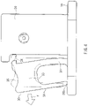
- FIG. 7 is a perspective view of the male connector 1 and the needleless port 100 in the connected and locked state.
- FIGS. 8A and 8B are cross-sectional views of the male connector 1 and the needleless port 100 in the connected and locked state. The cross-sections in FIGS. 8A and 8B are the same as the cross-sections in FIGS. 6A and 6B respectively.
- the lock lever 30 is at approximately the same position as in the initial state (see FIGS. 1 , 2A , 2B , 3A, and 3B ), and the claw 34 thereof (particularly the engaging face 34b thereof (see FIGS. 2B and 3A )) is engaged with the protruding portion 112 of the needleless port 100.
- the male luer 10 has passed through the slit 102 in the septum 101, and thus the septum 101 is undergoing a large amount of elastic deformation.
- the openings of the lateral hole 12 in the male luer 10 are exposed inside the inner cavity of the base portion 110. In this state, a liquid can be caused to flow between the male luer 10 and the needleless port 100 via the channel 11 and the lateral hole 12.
- the male connector 1 and the needleless port 100 can be separated by pressing a finger against the operation portion 35 of the lock lever 30 and displacing the lock lever 30 in the direction of separation from the hood 20 (see FIG. 4 ). The engagement between the claw 34 and the protruding portion 112 thus is canceled. If, at the same time, the needleless port 100 and the male connector 1 are pulled in the direction of separation from each other, the male connector 1 and the needleless port 100 can be separated. Immediately after the male luer 10 is withdrawn from the septum 101, the septum 101 undergoes elastic restoration, and the slit 102 closes.
- the claw 34 of the male connector 1 engages with the protruding portion 112 of the needleless port 100. Accordingly, the male luer 10 is prevented from unintentionally coming out of the septum 101.
- the direction in which the claw 34 needs to be moved in order to cancel the engagement between the claw 34 and the protruding portion 112 is the same as the direction of the force F (see FIG. 4 ) that needs to be applied to the operation portion 35 in order to move the claw 34 in the direction for canceling the engagement. Accordingly, the operation for canceling the locked state can be performed intuitively. Also, arranging the operation portion 35 at a position farther away from the fixed end of the lock lever 30 enables the amount of force F needed to cancel the engagement between the claw 34 and the protruding portion 112 to be reduced. Furthermore, arranging the claw 34 at a position farther from the fixed end of the lock lever 30 enables the displacement amount of the claw 34 to be increased.
- the operator can engage the claw 34 and the protruding portion 112 by merely pressing the needleless port 100 into the hood 20, without needing to touch the lock lever 30 with his/her hand.
- the ease of performing the connection operation is therefore favorable.
- the stopper 38 of the lock lever 30 and the base 19 function as a displacement limiting means that limits the upper limit of the elastic displacement amount of the lock lever 30.
- the displacement limiting means prevents the operator from greatly displacing the lock lever 30 more than necessary when canceling the engagement between the claw 34 and the protruding portion 112, thus making it possible to prevent the elastic portion 31 from becoming plastically deformed or damaged by excessive bending deformation.
- hood 20 surrounds the male luer 10, there is a reduced possibility of the operator mistakenly touching the male luer 10 with his/her hand. This is advantageous in keeping the operator away from dangerous drug solutions and blood.
- the hood 20 contributes to the positioning of the needleless port 100 in the horizontal plane as well. Specifically, the hood 20 positions the needleless port 100 relative to the male luer 10 such that the male luer 10 is precisely inserted into the slit 102 in the septum 101 that is exposed inside the opening 131 of the cap 130. Also, the hood 20 positions the needleless port 100 relative to the lock lever 30 such that the claw 34 reliably engages with the protruding portion 112, or such that the engagement between the claw 34 and the protruding portion 112 is reliably canceled.
- the opening 21 for allowing the claw 34 to engage with the needleless port 100 is formed in the hood 20. If it only is necessary that the claw 34 provided on the lock lever 30 that is arranged outside the hood 20 engages with the needleless port 100 inside the hood 20, it is possible to apply a method of, for example, reducing the height (up-down direction dimension) of the hood 20 or forming a notch extending toward the base 19 in the upper edge 20a of the hood 20. However, the method of reducing the height of the hood 20 reduces the above-described functionality of the hood 20 (i.e., the separation function of preventing the operator from touching the male luer 10, and the function of positioning the needleless port 100).
- the method of forming a notch in the edge 20a of the hood 20 reduces the mechanical strength of the edge 20a of the hood 20.
- the configuration of the present embodiment, in which the opening 21 is formed in the hood 20 and the claw 34 is engaged with the needleless port 100 via the opening 21, is advantageous in preventing the operator from mistakenly touching the male luer 10, in positioning the needleless port 100 using the hood 20, and in suppressing a reduction in the mechanical strength of the hood 20.
- the opening 21 formed in the hood 20 does not extend to the upper end of the hood 20.
- the hood 20 includes the bridge portion 22 at a position higher than the opening 21.
- the upper edge 20a of the hood 20 is continuous in the circumferential direction with the same height. This improves the strength of the upper edge 20a of the hood 20. Accordingly, in the case where external force in the horizontal direction acts on the needleless port 100 in the locked state ( FIGS. 7 , 8A, and 8B ), the hood 20 suppresses inclination and movement of the needleless port 100.
- the channel 11 of the male luer 10 is not open at the tip face 10t of the male luer 10, and the lateral hole 12 in communication with the channel 11 is open at the outer circumferential face of the male luer 10.
- the male luer 10 that has passed through the septum 101 is withdrawn from the septum 101 at a later time, liquid attached to the periphery of the openings of the lateral hole 12 is likely to be scraped away by the edges of the slit 102 in the septum 101, and therefore the above configuration is advantageous in reducing the amount of liquid that remains in the periphery of the openings of the lateral hole 12 after withdrawal from the septum 101.
- the shape of the lock lever 30 can be changed as desired.
- the operation portion 35 is a concave curved face having an approximately cylindrical face shape in the above embodiment, the shape and position of the operation portion 35 can be set as desired as long as force F in the direction of separation from the male luer 10 (see FIG. 4 ) can be applied to the lock lever 30.
- the operation portion 35 may be a protrusion for catching a finger, or a hole for the insertion of a finger.
- the stopper 38 may be omitted.
- the fixed end of the lock lever 30 is provided on the base 19, it may be provided on the hood 20.
- the portion of the needleless port that the claw 34 engages with may be changed appropriately according to the configuration of the needleless port.
- the shape and position of the claw 34 can be changed according to the portion for engaging with the needleless port.
- the shape of the hood 20 is also not limited to the above embodiment.
- a notch for avoiding interference with a tube connected to the coinfusion port may be formed in the upper edge 20a of the hood 20.
- the opening 21 does not need to reach the base 19, and it may be a small opening to the extent that only the claw 34 can be inserted.
- the lateral hole 12 of the male luer 10 extends along a straight line orthogonal to the central axis 10a (i.e., along the radial direction) in the above embodiment, the present invention is not limited to this, and it may extend along a straight line that intersects the central axis 10a at an angle other than a right angle.
- the number of lateral holes 12 is also not limited to the number in the above embodiment, and can be changed as desired. Also, a configuration is possible in which the lateral hole 12 is not formed, and the channel 11 is open at the tip face 10t of the male luer 10.
- a cover may be attached to the male member such that the opening of the channel on tip side of the male member is not exposed when the male member is not connected to a female connector.
- This cover is made of a flexible material having rubber elasticity, and when the male member is connected to a female connector, the cover undergoes elastic compression deformation while the male member passes through it (see WO 2010/061742 and WO 2010/061743 ).
- the present invention can be used in a wide range as a male connector in which the state of connection to a female connector needs to be reliably maintained continuously.
- the present invention can be preferably used in medical field that handle dangerous drugs (e.g., anticancer drugs), blood, and the like.
- the present invention can be used in various types of fields that handle liquids for uses other than medical use, such as food substances.
Description
- The present invention relates to a male connector that includes a lock mechanism for maintaining a state of connection to a female connector.
- When giving a patient an infusion or blood transfusion or performing extracorporeal blood circulation in surgery, it is necessary to form a channel (transport line) for transporting a liquid such as a drug solution or blood. Transport lines generally are formed by connecting containers, various types of instruments, feed tubes, and the like. Also, when a drug solution to be administered to a patient is injected into a drug solution bag (container), it is necessary to connect the drug solution bag and a syringe or the like. In this way, a male connector and a female connector are used to interconnect different members detachably.
- One known example of a female connector used in this application is a needleless port that has a disk-shaped partition wall member (hereinafter referred to as a "septum") that is made of an elastic material such as rubber and has a linear slit (incision) formed in the central portion (e.g., see
JP 3389983 B - There are cases where the drug solution contains a drug designated as a dangerous drug, such as some anticancer drugs. There are also cases where blood contains a pathogen or the like. Accordingly, it is necessary to avoid a situation where a connected male connector and female connector unintentionally become separated, and as a result a liquid such as a drug solution or blood leaks out and comes into contact with the operator's finger or the like, or the operator inhales vapor from the liquid.
- In view of this, a prior
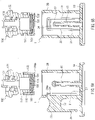
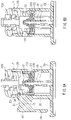
art male connector 900 with a lock mechanism has been previously proposed in which, as shown inFIGS. 9A and 9B , amale luer 910 is provided with a lock mechanism for maintaining a state in which themale luer 910 is connected to a needleless port (e.g., seeJP 2004-483 A WO 2010/061742 andWO 2010/061743 ). This prior art lock mechanism includes a pair oflock levers 930 arranged so as to be approximately parallel to themale luer 910 and sandwich themale luer 910. Thelock levers 930 are connected to abase end portion 919 of themale luer 910 viasupport pieces 931 provided at an approximately central position in the lengthwise direction of thelock levers 930. Aclaw 934 that engages with the needleless port is formed on one end of each of the lock levers 930, on the surface on the side that opposes the male luer. The end portions of the lock levers 930 on the side not provided with theclaws 934 areoperation portions 935 for operating the lock levers. When theoperation portions 935 of the pair oflock levers 930 are pressed toward each other, thesupport pieces 931 undergo elastic deformation, and thelock levers 930 become displaced in the direction in which theclaws 934 move away from themale luer 910. Numeral 920 indicates an approximately cylindrical hood that surrounds themale luer 910 and is fixed to thebase end portion 919. The pair oflock levers 930 are arranged in notches provided in thehood 920. Numeral 915 indicates a tubular portion that is in communication with themale luer 910 and is for connection to a flexible tube (not shown). - As shown in
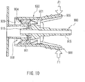
FIG. 10 , the priorart male luer 910 is inserted into aseptum 951 of aneedleless port 950, and theclaws 934 provided on the tips of the pair oflock levers 930 are engaged with a step on the outer circumferential face of theneedleless port 950. Accordingly, the state of connection of theneedleless port 950 and themale luer 910 is locked. Even if themale connector 900 and theneedleless port 950 are pulled away from each other, themale connector 900 and theneedleless port 950 cannot be separated since theclaws 934 of thelock levers 930 are engaged with theneedleless port 950. The priorart male connector 900 and theneedleless port 950 can be separated by applying force F1 to theoperation portions 935 of the pair oflock levers 930 in a direction in which they approach each other, so as to displace thelock levers 930 and cancel the engagement between theclaws 934 of thelock levers 930 and theneedleless port 950. -
JP 2012034738 A -
US 5582600 A discloses a connector assembly for fluid communication having a key component and a lid lock component, the lid lock component including a removably lockable lid. - With the above-described prior art lock mechanism including the pair of
lock levers 930, the locked state can be canceled by applying the pressing force F1 to theoperation portions 935 of thelock levers 930. Accordingly, if an unintended external force is applied to theoperation portions 935 of the lock levers 930, there is a possibility of the locked state becoming canceled. - An object of the present invention is to provide a male connector with a lock mechanism that is highly safe and has a reduced possibility of the locked state being unintentionally canceled by external force.
- According to the invention there is provided a male connector and a corresponding female connector, the male connector comprising: a bar-shaped male member for insertion into the female connector; and a lock mechanism for maintaining a state in which the male member is inserted into the female connector, wherein the lock mechanism includes: a hood that is arranged so as to surround a periphery of the male member and is for insertion of the female connector; and characterised in that the lock mechanism includes: a single lock lever having a cantilever support structure capable of elastic displacement, wherein the lock lever includes: a claw for engaging with the female connector; and an operation portion for elastically displacing the lock lever in a direction of separation from the male member, wherein the claw and the operation portion are provided on a free end side of the lock lever, and in use, when the female connector is connected to the male connector, the claw engages with the female connector so that the male member is prevented from coming out of the female connector.
- According to the lock mechanism of the present invention, the claw provided on the single lock lever can be engaged with the female connector inserted into the hood, thus making it possible to maintain the state in which the male member is connected to the female connector. Also, canceling the engagement between the claw and the female connector requires displacing the lock lever in the direction of moving away from the male member, and thus there is a low possibility of the locked state achieved by the lock mechanism being unintentionally canceled by external force. Accordingly, it is possible to provide a male connector with a lock mechanism that is highly safe.
-
- [
FIG. 1] FIG. 1 is a perspective view of a male connector with a lock mechanism according to an embodiment of the present invention. - [
FIG. 2] FIG. 2A is a plan view of the male connector with a lock mechanism according to the embodiment of the present invention.FIG. 2B is a side view of the same. - [
FIG. 3] FIG. 3A is a cross-sectional arrow view of the male connector with a lock mechanism according to the embodiment of the present invention taken along a plane including aline 3A-3A inFIG. 2A .FIG. 3B is a cross-sectional arrow view of the male connector with a lock mechanism according to the embodiment of the present invention taken along a plane including aline 3B-3B inFIG. 2A . - [
FIG. 4] FIG. 4 is a side view of an elastically deformed lock lever in the male connector with a lock mechanism according to the embodiment of the present invention. - [
FIG. 5] FIG. 5 is a perspective view of a female connector and the male connector with a lock mechanism according to the embodiment of the present invention immediately before connection. - [
FIG. 6] FIGS. 6A and 6B are cross-sectional views of the female connector and the male connector with a lock mechanism according to the embodiment of the present invention immediately before connection. - [
FIG. 7] FIG. 7 is a perspective view of the female connector and the male connector with a lock mechanism according to the embodiment of the present invention, in which the connected state is locked by the lock mechanism. - [
FIG. 8] FIGS. 8A and 8B are cross-sectional views of the female connector and the male connector with a lock mechanism according to the embodiment of the present invention, in which the connected state is locked by the lock mechanism. - [
FIG. 9] FIG. 9A is a side view of a conventional male connector with a lock mechanism, andFIG. 9B is a cross-sectional view of the same. - [
FIG. 10] FIG. 10 is a cross-sectional view of the conventional male connector with a lock mechanism when connected to a needleless port. - A male connector with a lock mechanism of the present invention includes a bar-shaped male member for insertion into a female connector, and a lock mechanism for maintaining a state in which the male member is inserted into the female connector. The lock mechanism includes a hood that is arranged so as to surround a periphery of the male member and is for insertion of the female connector, and a single lock lever having a cantilever support structure capable of elastic displacement. The lock lever includes a claw for engaging with the female connector, and an operation portion for elastically displacing the lock lever in a direction of separation from the male member. The claw and the operation portion are provided on a free end side of the lock lever.
- It is preferable that the above male connector with a lock mechanism of the present invention further includes a displacement limiting means that sets an upper limit of an elastic displacement amount of the lock lever. According to this, it is possible to prevent the lock lever from becoming plastically deformed or damaged due to an operator greatly displacing the lock lever more than necessary.
- It is preferable that an opening for allowing engagement of the claw to the female connector is formed in the hood. Compared to a configuration in which the height of the hood is reduced or a notch is formed in the upper edge of the hood, this preferable configuration is advantageous in preventing an operator from mistakenly touching the male member, in positioning the female connector using the hood, and in suppressing a reduction in the mechanical strength of the hood.
- It is preferable that the hood includes a bridge portion on a side on which the female connector is inserted relative to the opening, and the bridge portion connects portions of the hood that sandwich the opening in a circumferential direction. According to this, even if external force acts on the female connector in the state of being connected and locked to the male connector, it is possible to suppress inclination and movement of the female connector. As a result, it is possible to reduce the possibility of the locked state being unintentionally canceled and the hood becoming damaged.
- It is preferable that a channel is formed in the male member, and a lateral hole in communication with the channel is open at an outer circumferential face of the male member. When the male member that has been inserted into the female connector is withdrawn from the female connector, liquid attached to the periphery of the opening of the lateral hole is scraped away by the female connector, and therefore according to the above configuration, it is possible to reduce the amount of liquid that remains in the periphery of the opening of the lateral hole after withdrawal from the female connector.
- The present invention will be described below in detail while disclosing preferred embodiments. However, it goes without saying that the present invention is not limited to the following embodiments. For the sake of convenience in the description, the drawings that are referenced in the following description show simplifications of, among the constituent members of the embodiment of the present invention, only the relevant members that are necessary for describing the present invention. The present invention therefore can include arbitrary constituent members that are not shown in the following drawings. Also, regarding the dimensions of the members in the drawings, the dimensions of the actual constituent members, the ratios of the dimensions of the members, and the like are not shown faithfully.
-
FIG. 1 is a perspective view of a male connector with a lock mechanism (referred to hereinafter as simply "male connector") 1 according to an embodiment of the present invention.FIG. 2A is a plan view of themale connector 1, andFIG. 2B is a side view of themale connector 1. Furthermore,FIG. 3A is a cross-sectional arrow view of themale connector 1 taken along a plane including aline 3A-3A inFIG. 2A , andFIG. 3B is a cross-sectional arrow view of themale connector 1 taken along a plane including aline 3B-3B inFIG. 2A . - The
male connector 1 of the present embodiment includes a bar-shapedmale luer 10 as a male member. InFIGS. 3A and 3B , 10a indicates the central axis of themale luer 10. For convenience in the following description, the lengthwise direction of the male luer 10 (direction parallel to thecentral axis 10a) will be referred to as the "up-down direction", and the direction orthogonal to the lengthwise direction of themale luer 10 will be referred to as the "horizontal direction". Also, with regard to the up-down direction, the side close to a base 19 will be referred to as the "lower side", and the side far from it will be referred to as the "upper side" or the "tip side". Note that the "up-down direction" and the "horizontal direction" do not mean orientations during actual use of themale connector 1. Furthermore, the direction of a line orthogonal to thecentral axis 10a of themale luer 10 will be referred to as the "radial direction", and the direction of rotation about thecentral axis 10a will be referred to as the "circumferential direction". - As shown in
FIGS. 3A and 3B , themale luer 10 is a bar-shaped member that protrudes from thebase 19. The outer circumferential face (i.e., side face) of themale luer 10 is a tapered face such that the outer diameter slightly decreases with increasing distance from the base 19 in the present embodiment. Note that the shape of the outer circumferential face of themale luer 10 is not limited to this, and any shape can be selected. For example, it may be a cylindrical face such that the outer diameter is constant in the up-down direction. - A
channel 11 is formed in themale luer 10 along the lengthwise direction thereof. Thechannel 11 is not open at atip face 10t of themale luer 10. Instead, alateral hole 12 that is in communication with thechannel 11 is formed in the vicinity of the tip of themale luer 10. Thelateral hole 12 passes through themale luer 10 in the radial direction, and is open at two locations on the outer circumferential face of themale luer 10. Note that thelateral hole 12 may be open at only one location on the outer circumferential face of themale luer 10 instead of passing completely throughmale luer 10. - The configuration of the base 19 on the side opposite to the
male luer 10 will not be described due to not being directly related to the present invention. Although theliquid channel 11 is open at the lower face of the base 19 in the present embodiment, theliquid channel 11 may be extended and put in communication with a desired channel. - A
hood 20 is provided upright on thebase 19 on the same side as themale luer 10 so as to surround themale luer 10. Thehood 20 is shaped as a hollow cylinder that is coaxial with themale luer 10, and the height (up-down direction dimension) of thehood 20 is greater than the height of themale luer 10. The inner circumferential face of the hood 20 (the face opposing the male luer 10) is a cylindrical face having an inner diameter approximately the same as or slightly greater than the outer diameter of a female connector to which themale connector 1 of the present embodiment is to be connected. An opening (through-hole) 21 is formed in thehood 20. Theopening 21 extends from the base 19 to a position slightly higher than themale luer 10. Theopening 21 does not extend to the upper end of thehood 20, and abridge portion 22 provided above theopening 21 connects portions of thehood 20 on the two sides of theopening 21 in the circumferential direction. Anupper edge 20a of thehood 20 has a circular shape in a plan view, and is continuous in the circumferential direction with the same height. - A
lock lever 30 is provided upright on the base 19 so as to oppose themale luer 10 via theopening 21 of thehood 20. Thelock lever 30 includes anelastic portion 31 that extends perpendicularly from thebase 19, alock piece 33 provided on the upper end of theelastic portion 31, and astopper 38 that extends from thelock piece 33 toward thebase 19, and as shown inFIGS. 2B and3A , thelock lever 30 is overall shaped as an upside "J" or an upside "U". - The
elastic portion 31 is shaped as a thin plate that extends along a plane orthogonal to the radial direction of themale luer 10. As a result, theelastic portion 31 is capable of being displaced so as to elastically bend in a plane that includes thecentral axis 10a of themale luer 10. - The
lock piece 33 is an approximately quadrangular plate-shaped member that extends along the radial direction of themale luer 10. The face of thelock piece 33 on the side opposing themale luer 10 is on the same plane as theelastic portion 31, and aclaw 34 that protrudes toward themale luer 10 is formed on the upper end of this face of thelock piece 33. As shown inFIGS. 2B and3A , theclaw 34 includes aninclined face 34a and anengaging face 34b. Theinclined face 34a is inclined so as to move away from themale luer 10 with increasing distance from thebase 19. The engagingface 34b is arranged on the base 19 side relative to theinclined face 34a, and is a flat face that is approximately parallel to the horizontal direction. As shown inFIG. 2A , the apex portion of the claw 34 (the portion closest to the male luer 10) protrudes to a position on themale luer 10 side relative to the inner circumferential face of thehood 20. - The upper face of the
lock piece 33 is anoperation portion 35 that is sunken so as to be shaped as an approximately cylindrical face. Theoperation portion 35 extends and protrudes outward along the radial direction from the outer circumferential face of thehood 20. - The
stopper 38 is elongated such that the face of thelock piece 33 on the side opposite to themale luer 10 extends toward thebase 19. Alower end 38b of thestopper 38 and the base 19 are separated via agap 39. - The
lock lever 30 has a cantilever support structure in which the lower end of theelastic portion 31 fixed to thebase 19 is the fixed end, and the upper end side provided with theclaw 34 and theoperation portion 35 is the free end. If a finger is brought into contact with theoperation portion 35, and force F in a direction of separation from thehood 20 is applied to theoperation portion 35, theelastic portion 31 undergoes elastic bending deformation, and thelower end 38b of thestopper 38 comes into contact with the base 19 as shown inFIG. 4 . At this time, theclaw 34 becomes displaced in a direction of separation from themale luer 10 approximately along the radial direction. - The
hood 20 and thelock lever 30 described above configure the lock mechanism of themale connector 1 of the present embodiment. - It is preferable that the
male luer 10, thebase 19, thehood 20, and thelock lever 30 are made of a hard material. Specifically, themale luer 10, thebase 19, thehood 20, and thelock lever 30 can be created with a method such as integral molding, using a resin material such as polyacetal, polycarbonate, polystyrene, polyamide, polypropylene, or rigid polyvinyl chloride. - The following describes operations of and a method of use of the
male connector 1 of the present embodiment configured as described above. -
FIG. 5 is a perspective view of themale connector 1 and aneedleless port 100 serving as the female connector, immediately before connection.FIGS. 6A and 6B are cross-sectional views of themale connector 1 and theneedleless port 100 immediately before connection. The cross-sections inFIGS. 6A and 6B are the same as the cross-sections inFIGS. 3A and 3B respectively. - The
needleless port 100 includes disk-shaped partition wall member (septum) 101 that is made of an elastic material such as rubber and is provided with a linear slit (incision) 102 in the central portion. Theseptum 101 is placed at the tip of atubular base portion 110, and is covered bycap 130. A lockingclaw 135 is formed by a notch in acylindrical portion 133 encompassing thecap 130, and thecap 130 is fixed to thebase portion 110 by engaging the lockingclaw 135 with a lockingclaw 115 formed on the outer circumferential face of thebase portion 110. Accordingly, theseptum 101 is sandwiched between thebase portion 110 and thecap 130. Anopening 131 is formed in the center of thecap 130, and theslit 102 in theseptum 101 is exposed inside theopening 131. A protrudingportion 112 is formed on the outer circumferential face of thebase portion 110 on the side opposite to theseptum 101, and protrudes so as to form a cylindrical face that is approximately the same as thecylindrical portion 133 of thecap 130. The protrudingportion 112 is continuous in the circumferential direction of thebase portion 110. Amale luer 120 having a tapered outer circumferential face, andfemale threading 122 that is coaxial with themale luer 120 are provided on the side opposite to thebase portion 110. Note that the configuration of the portions of theneedleless port 100 on the side opposite to thebase portion 110 are not limited to this, and these portions can have any configuration. - As shown in
FIGS. 5 ,6A, and 6B , theneedleless port 100 is placed in opposition to themale connector 1. Thecap 130 of theneedleless port 100 is then inserted into thehood 20 of themale connector 1, and then theneedleless port 100 is pushed toward themale connector 1. The tip of themale luer 10 then comes into contact with theseptum 101 that is exposed inside theopening 131 of thecap 130, and enters theslit 102. At the same time, theinclined face 34a of theclaw 34 of thelock lever 30 comes into contact with anouter edge 130a of thecap 130. While sliding over theinclined face 34a, theedge 130a of thecap 130 causes theelastic portion 31 to undergo deformation so as to elastically bend, and displaces thelock lever 30 in the direction in which theclaw 34 moves away from themale luer 10. As theneedleless port 100 enters thehood 20, theclaw 34 slides over thecylindrical portion 133 of thecap 130 and the protrudingportion 112 in the stated order. Then, when theclaw 34 has completely passed the protrudingportion 112, theelastic portion 31 undergoes elastic restoration, and theclaw 34 and the protrudingportion 112 engage with each other (enter a locked state). -
FIG. 7 is a perspective view of themale connector 1 and theneedleless port 100 in the connected and locked state.FIGS. 8A and 8B are cross-sectional views of themale connector 1 and theneedleless port 100 in the connected and locked state. The cross-sections inFIGS. 8A and 8B are the same as the cross-sections inFIGS. 6A and 6B respectively. - The
lock lever 30 is at approximately the same position as in the initial state (seeFIGS. 1 ,2A ,2B ,3A, and 3B ), and theclaw 34 thereof (particularly the engagingface 34b thereof (seeFIGS. 2B and3A )) is engaged with the protrudingportion 112 of theneedleless port 100. Themale luer 10 has passed through theslit 102 in theseptum 101, and thus theseptum 101 is undergoing a large amount of elastic deformation. The openings of thelateral hole 12 in themale luer 10 are exposed inside the inner cavity of thebase portion 110. In this state, a liquid can be caused to flow between themale luer 10 and theneedleless port 100 via thechannel 11 and thelateral hole 12. - The
male connector 1 and theneedleless port 100 can be separated by pressing a finger against theoperation portion 35 of thelock lever 30 and displacing thelock lever 30 in the direction of separation from the hood 20 (seeFIG. 4 ). The engagement between theclaw 34 and the protrudingportion 112 thus is canceled. If, at the same time, theneedleless port 100 and themale connector 1 are pulled in the direction of separation from each other, themale connector 1 and theneedleless port 100 can be separated. Immediately after themale luer 10 is withdrawn from theseptum 101, theseptum 101 undergoes elastic restoration, and theslit 102 closes. - As described above, according to the present embodiment, in the state where the
male luer 10 has passed through theseptum 101, theclaw 34 of themale connector 1 engages with the protrudingportion 112 of theneedleless port 100. Accordingly, themale luer 10 is prevented from unintentionally coming out of theseptum 101. - In order to cancel the engagement between the
claw 34 and the protrudingportion 112, it is necessary to displace thelock lever 30 in the direction of separation from thehood 20. With the prior art lock mechanism that includes the lock levers 930 (seeFIG. 10 ), if pressing force F1 in the direction of approaching thetubular portion 915 is unintentionally applied to theoperation portions 935, there is the possibility of the engagement between theclaws 934 of the lock levers 930 and theneedleless port 950 being canceled. In contrast, with the lock mechanism of the present embodiment, the engagement between theclaw 34 and the protrudingportion 112 is not canceled even if pressing force in the direction of approaching themale luer 10 is applied to any portion of thelock lever 30. Conversely, if force (pulling force) F in the direction of approaching the side opposite to the male luer 10 (seeFIG. 4 ) unintentionally acts on thelock lever 30, there is the possibility of the engagement between theclaw 34 and the protrudingportion 112 being canceled. However, the possibility of this pulling force F acting on thelock lever 30 in actual use is very low compared to the possibility of pressing force in the opposite direction acting on thelock lever 30. Accordingly, the lock mechanism of the present embodiment is very safe and has a reduced possibility of the locked state being unintentionally canceled due to external force. - Since the
claw 34 and theoperation portion 35 are provided on the free end side of thelock lever 30, the direction in which theclaw 34 needs to be moved in order to cancel the engagement between theclaw 34 and the protrudingportion 112 is the same as the direction of the force F (seeFIG. 4 ) that needs to be applied to theoperation portion 35 in order to move theclaw 34 in the direction for canceling the engagement. Accordingly, the operation for canceling the locked state can be performed intuitively. Also, arranging theoperation portion 35 at a position farther away from the fixed end of thelock lever 30 enables the amount of force F needed to cancel the engagement between theclaw 34 and the protrudingportion 112 to be reduced. Furthermore, arranging theclaw 34 at a position farther from the fixed end of thelock lever 30 enables the displacement amount of theclaw 34 to be increased. - Since only one
lock lever 30 is provided, the locked state can be canceled with one finger, thus improving the ease of the operation for canceling the locked state. Also, the lower the number of lock levers 30 is, the lower the possibility of unintended external force acting on thelock lever 30 is. Accordingly, providing only onelock lever 30 reduces the possibility of the pulling force F for canceling the engagement between theclaw 34 and the protrudingportion 112 unintentionally acting on thelock lever 30, thus further improving safety. - With the prior art lock mechanism having a pair of lock levers 930 (see
FIG. 10 ), twoclaws 934 engage with theneedleless port 950. Accordingly, the twoclaws 934 need to be disengaged from theneedleless port 950 in order to cancel the locked state achieved by the lock levers 930. However, even if the pressing force F1 is applied to the twooperation portions 935 so as to widen the gap between the twoclaws 934, there are cases where the engagements of both of the twoclaws 934 to theneedleless port 950 cannot be canceled at the same time. In this case, the engagements of the twoclaws 934 need to be canceled one at a time in order while the gap between the twoclaws 934 is widened. Accordingly, there has been the problem that the operation for canceling the locked state is cumbersome. In contrast, with the present embodiment, only oneclaw 34 for engagement with theneedleless port 100 is provided, thus making it possible to cancel the locked state merely by applying the force F to theoperation portion 35 so as to displace thelock lever 30. Accordingly, the operation for canceling the locked state is easy, and operability is improved. - Since the
inclined face 34a is formed on theclaw 34 on the side opposite to thebase 19, in the process of connecting themale connector 1 and theneedleless port 100, the operator can engage theclaw 34 and the protrudingportion 112 by merely pressing theneedleless port 100 into thehood 20, without needing to touch thelock lever 30 with his/her hand. The ease of performing the connection operation is therefore favorable. - If the force F is applied to the
operation portion 35 so as to displace thelock lever 30 in the direction of separation from themale luer 10, thelower end 38b of thestopper 38 comes into contact with thebase 19, and thus the displacement of thelock lever 30 is limited. In this way, thestopper 38 of thelock lever 30 and the base 19 function as a displacement limiting means that limits the upper limit of the elastic displacement amount of thelock lever 30. The displacement limiting means prevents the operator from greatly displacing thelock lever 30 more than necessary when canceling the engagement between theclaw 34 and the protrudingportion 112, thus making it possible to prevent theelastic portion 31 from becoming plastically deformed or damaged by excessive bending deformation. - Since the
hood 20 surrounds themale luer 10, there is a reduced possibility of the operator mistakenly touching themale luer 10 with his/her hand. This is advantageous in keeping the operator away from dangerous drug solutions and blood. - Furthermore, the
hood 20 contributes to the positioning of theneedleless port 100 in the horizontal plane as well. Specifically, thehood 20 positions theneedleless port 100 relative to themale luer 10 such that themale luer 10 is precisely inserted into theslit 102 in theseptum 101 that is exposed inside theopening 131 of thecap 130. Also, thehood 20 positions theneedleless port 100 relative to thelock lever 30 such that theclaw 34 reliably engages with the protrudingportion 112, or such that the engagement between theclaw 34 and the protrudingportion 112 is reliably canceled. - The
opening 21 for allowing theclaw 34 to engage with theneedleless port 100 is formed in thehood 20. If it only is necessary that theclaw 34 provided on thelock lever 30 that is arranged outside thehood 20 engages with theneedleless port 100 inside thehood 20, it is possible to apply a method of, for example, reducing the height (up-down direction dimension) of thehood 20 or forming a notch extending toward the base 19 in theupper edge 20a of thehood 20. However, the method of reducing the height of thehood 20 reduces the above-described functionality of the hood 20 (i.e., the separation function of preventing the operator from touching themale luer 10, and the function of positioning the needleless port 100). Also, the method of forming a notch in theedge 20a of thehood 20 reduces the mechanical strength of theedge 20a of thehood 20. The configuration of the present embodiment, in which theopening 21 is formed in thehood 20 and theclaw 34 is engaged with theneedleless port 100 via theopening 21, is advantageous in preventing the operator from mistakenly touching themale luer 10, in positioning theneedleless port 100 using thehood 20, and in suppressing a reduction in the mechanical strength of thehood 20. - The
opening 21 formed in thehood 20 does not extend to the upper end of thehood 20. Thehood 20 includes thebridge portion 22 at a position higher than theopening 21. As a result, theupper edge 20a of thehood 20 is continuous in the circumferential direction with the same height. This improves the strength of theupper edge 20a of thehood 20. Accordingly, in the case where external force in the horizontal direction acts on theneedleless port 100 in the locked state (FIGS. 7 ,8A, and 8B ), thehood 20 suppresses inclination and movement of theneedleless port 100. This prevents the engagement between theclaw 34 and the protrudingportion 112 from being canceled by inclination or movement of theneedleless port 100, thus further reducing the possibility of the locked state being unintentionally canceled, and further improving safety. Also, it is possible to prevent thehood 20 from being damaged by inclination or movement of theneedleless port 100. - The
channel 11 of themale luer 10 is not open at thetip face 10t of themale luer 10, and thelateral hole 12 in communication with thechannel 11 is open at the outer circumferential face of themale luer 10. When themale luer 10 that has passed through theseptum 101 is withdrawn from theseptum 101 at a later time, liquid attached to the periphery of the openings of thelateral hole 12 is likely to be scraped away by the edges of theslit 102 in theseptum 101, and therefore the above configuration is advantageous in reducing the amount of liquid that remains in the periphery of the openings of thelateral hole 12 after withdrawal from theseptum 101. - The above embodiment is merely an illustrative example. The present invention is not limited to the above embodiment, and can be modified as appropriate.
- As long as the
lock lever 30 has a claw that engages with theneedleless port 100 and an operation portion for displacing thelock lever 30 in order to cancel the locked state, the shape of thelock lever 30 can be changed as desired. For example, although theoperation portion 35 is a concave curved face having an approximately cylindrical face shape in the above embodiment, the shape and position of theoperation portion 35 can be set as desired as long as force F in the direction of separation from the male luer 10 (seeFIG. 4 ) can be applied to thelock lever 30. For example, theoperation portion 35 may be a protrusion for catching a finger, or a hole for the insertion of a finger. Thestopper 38 may be omitted. Although the fixed end of thelock lever 30 is provided on thebase 19, it may be provided on thehood 20. - Although the
claw 34 is engaged with the protrudingportion 112 of theneedleless port 100 in the above embodiment, the portion of the needleless port that theclaw 34 engages with may be changed appropriately according to the configuration of the needleless port. The shape and position of theclaw 34 can be changed according to the portion for engaging with the needleless port. - The shape of the
hood 20 is also not limited to the above embodiment. For example, if theneedleless port 100 configures a coinfusion port (e.g., seeJP 3389983 B upper edge 20a of thehood 20. Also, theopening 21 does not need to reach thebase 19, and it may be a small opening to the extent that only theclaw 34 can be inserted. - Although the
lateral hole 12 of themale luer 10 extends along a straight line orthogonal to thecentral axis 10a (i.e., along the radial direction) in the above embodiment, the present invention is not limited to this, and it may extend along a straight line that intersects thecentral axis 10a at an angle other than a right angle. The number oflateral holes 12 is also not limited to the number in the above embodiment, and can be changed as desired. Also, a configuration is possible in which thelateral hole 12 is not formed, and thechannel 11 is open at thetip face 10t of themale luer 10. - A cover may be attached to the male member such that the opening of the channel on tip side of the male member is not exposed when the male member is not connected to a female connector. This cover is made of a flexible material having rubber elasticity, and when the male member is connected to a female connector, the cover undergoes elastic compression deformation while the male member passes through it (see
WO 2010/061742 andWO 2010/061743 ). - Although there are no particular limitations on the field of use of the present invention, it can be used in a wide range as a male connector in which the state of connection to a female connector needs to be reliably maintained continuously. In particular, the present invention can be preferably used in medical field that handle dangerous drugs (e.g., anticancer drugs), blood, and the like. Furthermore, the present invention can be used in various types of fields that handle liquids for uses other than medical use, such as food substances.
-
- 1
- Male connector
- 10
- Male luer (male member)
- 11
- Channel
- 12
- Lateral hole
- 20
- Hood
- 20a
- Edge of hood
- 21
- Opening
- 22
- Bridge portion
- 30
- Lock lever
- 31
- Elastic portion
- 34
- Claw
- 35
- Operation portion
- 38
- Stopper (displacement limiting means)
- 100
- Needleless port (female connector)
Claims (5)
- A male connector (1) and a corresponding female connector (100), the male connector comprising:a bar-shaped male member (10) for insertion into the female connector (100); anda lock mechanism for maintaining a state in which the male member is inserted into the female connector,wherein the lock mechanism includes:wherein the lock lever includes:
a hood (20) that is arranged so as to surround a periphery of the male member and is for insertion of the female connector; and characterised in that the lock mechanism includes:
a single lock lever (30) having a cantilever support structure capable of elastic displacement,a claw (34) for engaging with the female connector; andan operation portion (35) for elastically displacing the lock lever in a direction of separation from the male member, whereinthe claw and the operation portion are provided on a free end side of the lock lever, andin use, when the female connector is connected to the male connector, the claw engages with the female connector so that the male member is prevented from coming out of the female connector. - The male connector and female connector according to claim 1, the male connector further comprising a displacement limiting means (38) that sets an upper limit of an elastic displacement amount of the lock lever.
- The male connector and female connector according to claim 1 or 2,
wherein an opening (21) for allowing engagement of the claw to the female connector is formed in the hood. - The male connector and female connector according to claim 3,
wherein the hood includes a bridge portion (22) on a side on which the female connector is inserted relative to the opening, the bridge portion connecting portions of the hood that sandwich the opening in a circumferential direction. - The male connector and female connector according to any of claims 1 to 4,
wherein a channel (11) is formed in the male member, and a lateral hole (12) in communication with the channel is open at an outer circumferential face of the male member.
Applications Claiming Priority (2)
| Application Number | Priority Date | Filing Date | Title |
|---|---|---|---|
| JP2012092292 | 2012-04-13 | ||
| PCT/JP2013/060493 WO2013154049A1 (en) | 2012-04-13 | 2013-04-05 | Male connector equipped with lock mechanism |
Publications (3)
| Publication Number | Publication Date |
|---|---|
| EP2837404A1 EP2837404A1 (en) | 2015-02-18 |
| EP2837404A4 EP2837404A4 (en) | 2016-07-20 |
| EP2837404B1 true EP2837404B1 (en) | 2022-10-26 |
Family
ID=49327614
Family Applications (1)
| Application Number | Title | Priority Date | Filing Date |
|---|---|---|---|
| EP13775776.1A Active EP2837404B1 (en) | 2012-04-13 | 2013-04-05 | Male connector equipped with lock mechanism |
Country Status (5)
| Country | Link |
|---|---|
| US (1) | US9775979B2 (en) |
| EP (1) | EP2837404B1 (en) |
| JP (1) | JP6094829B2 (en) |
| CN (1) | CN104220124B (en) |
| WO (1) | WO2013154049A1 (en) |
Families Citing this family (9)
| Publication number | Priority date | Publication date | Assignee | Title |
|---|---|---|---|---|
| JP6094830B2 (en) | 2012-04-13 | 2017-03-15 | 株式会社ジェイ・エム・エス | Male connector with locking mechanism |
| CA2977030A1 (en) * | 2015-02-18 | 2016-08-25 | Jms Co., Ltd. | Lever lock male connector and male connector assembly |
| WO2016152169A1 (en) * | 2015-03-26 | 2016-09-29 | テルモ株式会社 | Medical connector |
| EP3299060B1 (en) | 2015-05-18 | 2022-04-13 | JMS Co., Ltd. | Lever lock-type male connector and male connector assembly |
| CA3061396A1 (en) * | 2018-11-30 | 2020-05-30 | Becton, Dickinson And Company | Tactile features to guide user interaction with fluid connector |
| GB201907070D0 (en) | 2019-05-20 | 2019-07-03 | Metis Design Bv | Connector for a gastrostomy device |
| DE102020202939A1 (en) | 2020-03-06 | 2021-09-09 | B. Braun Melsungen Aktiengesellschaft | Coupling element for a closed fluid transfer system, mating coupling element for such a coupling element and coupling system |
| AU2021356704A1 (en) | 2020-10-09 | 2023-06-01 | Icu Medical, Inc. | Fluid transfer device and method of use for same |
| WO2023278503A1 (en) * | 2021-07-02 | 2023-01-05 | Becton, Dickinson And Company | Protective cover for a medical device |
Family Cites Families (20)
| Publication number | Priority date | Publication date | Assignee | Title |
|---|---|---|---|---|
| US5688254A (en) * | 1983-01-24 | 1997-11-18 | Icu Medical, Inc. | Medical connector |
| US5964785A (en) * | 1988-01-25 | 1999-10-12 | Baxter International Inc. | Bayonet look cannula for pre-slit y-site |
| IE66526B1 (en) | 1989-03-17 | 1996-01-24 | Baxter Int | A pre-slit injection site usable with a blunt cannula |
| MX172729B (en) | 1989-11-09 | 1994-01-10 | Baxter Int | DEVICE FOR CANNULA INSERTION |
| US5122123A (en) * | 1991-01-30 | 1992-06-16 | Vaillancourt Vincent L | Closed system connector assembly |
| US5496274A (en) * | 1992-11-23 | 1996-03-05 | Becton, Dickinson And Company | Locking safety needle assembly |
| US5582600A (en) | 1995-08-03 | 1996-12-10 | Baxter International Inc. | Transfer set connector with a locking lid and a method of using the same |
| JP3389983B2 (en) | 1997-10-23 | 2003-03-24 | 株式会社ジェイ・エム・エス | Medical injection port |
| US20020173748A1 (en) | 1998-10-29 | 2002-11-21 | Mcconnell Susan | Reservoir connector |
| CA2533850C (en) * | 1998-10-29 | 2009-09-01 | Medtronic Minimed, Inc. | Reservoir connector |
| JP4163975B2 (en) | 2002-02-25 | 2008-10-08 | 株式会社ジェイ・エム・エス | Lock connector for communication with connection port member with bulkhead |
| JP5067600B2 (en) | 2006-06-22 | 2012-11-07 | 株式会社ジェイ・エム・エス | Lock connector for communication |
| FR2931363B1 (en) | 2008-05-23 | 2010-06-25 | Vygon | CONNECTOR FOR LIQUID CIRCUIT, IN PARTICULAR FOR MEDICAL USE AND USE OF SUCH A CONNECTOR |
| JP5209400B2 (en) * | 2008-08-06 | 2013-06-12 | スーガン株式会社 | Connector lock cover |
| EP2351550A1 (en) | 2008-11-25 | 2011-08-03 | JMS Co., Ltd. | Connector |
| US8556879B2 (en) | 2008-11-25 | 2013-10-15 | Jms Co., Ltd. | Connector |
| ES2691425T3 (en) | 2010-05-21 | 2018-11-27 | Carmel Pharma Ab | Connector, fluid container |
| WO2011156521A2 (en) * | 2010-06-08 | 2011-12-15 | Dotted Intellectual Property, Llc | Connector assembly |
| JP5678510B2 (en) | 2010-08-04 | 2015-03-04 | 株式会社ジェイ・エム・エス | Medical connector |
| US20120286186A1 (en) * | 2011-05-11 | 2012-11-15 | Spolski Kevin J | Valve for Regulating the Flow of A Liquid |
-
2013
- 2013-04-05 EP EP13775776.1A patent/EP2837404B1/en active Active
- 2013-04-05 CN CN201380019763.4A patent/CN104220124B/en active Active
- 2013-04-05 JP JP2014510150A patent/JP6094829B2/en active Active
- 2013-04-05 WO PCT/JP2013/060493 patent/WO2013154049A1/en active Application Filing
- 2013-04-05 US US14/391,349 patent/US9775979B2/en active Active
Also Published As
| Publication number | Publication date |
|---|---|
| US20150105753A1 (en) | 2015-04-16 |
| JPWO2013154049A1 (en) | 2015-12-17 |
| EP2837404A1 (en) | 2015-02-18 |
| CN104220124B (en) | 2016-12-14 |
| EP2837404A4 (en) | 2016-07-20 |
| US9775979B2 (en) | 2017-10-03 |
| JP6094829B2 (en) | 2017-03-15 |
| WO2013154049A1 (en) | 2013-10-17 |
| CN104220124A (en) | 2014-12-17 |
Similar Documents
| Publication | Publication Date | Title |
|---|---|---|
| EP2837403B1 (en) | Male connector equipped with lock mechanism | |
| EP2837404B1 (en) | Male connector equipped with lock mechanism | |
| CN110448461B (en) | Syringe adapter with disconnect feedback mechanism | |
| JP6140916B2 (en) | Medical male parts | |
| JP5746127B2 (en) | Method and apparatus for delivering a therapeutic agent through an injection port | |
| EP4218895A1 (en) | Syringe adapter with lock mechanism | |
| JP5994400B2 (en) | Female connector | |
| CN109069802B (en) | Ergonomic IV systems and methods | |
| EP2495010A1 (en) | Connector assembly | |
| JP2014030489A (en) | Infusion set, and method of using the same | |
| JP5607637B2 (en) | Connecting device and infusion tube set | |
| EP3260161A1 (en) | Lever lock male connector and male connector assembly | |
| JP6834204B2 (en) | Male connector | |
| JP6318531B2 (en) | Male connector, female connector, and connector set | |
| WO2016021323A1 (en) | Needle assembly | |
| US11383031B2 (en) | Catheter assembly | |
| JP7163617B2 (en) | Lever lock type male connector | |
| JP6741209B2 (en) | Filter assembly | |
| CN211935048U (en) | Catheter system and needle shield device | |
| JP2014028006A (en) | Access port | |
| JP7223265B2 (en) | adapter | |
| JP7371495B2 (en) | Connector | |
| JP2016154617A (en) | Indwelling needle device | |
| CN112334228A (en) | Closure for a biological fluid collection device | |
| JP2016182188A (en) | Detention needle device |
Legal Events
| Date | Code | Title | Description |
|---|---|---|---|
| PUAI | Public reference made under article 153(3) epc to a published international application that has entered the european phase |
Free format text: ORIGINAL CODE: 0009012 |
|
| 17P | Request for examination filed |
Effective date: 20141010 |
|
| AK | Designated contracting states |
Kind code of ref document: A1 Designated state(s): AL AT BE BG CH CY CZ DE DK EE ES FI FR GB GR HR HU IE IS IT LI LT LU LV MC MK MT NL NO PL PT RO RS SE SI SK SM TR |
|
| AX | Request for extension of the european patent |
Extension state: BA ME |
|
| DAX | Request for extension of the european patent (deleted) | ||
| RA4 | Supplementary search report drawn up and despatched (corrected) |
Effective date: 20160617 |
|
| RIC1 | Information provided on ipc code assigned before grant |
Ipc: A61M 39/02 20060101AFI20160613BHEP Ipc: A61J 1/14 20060101ALI20160613BHEP Ipc: A61M 39/10 20060101ALI20160613BHEP |
|
| STAA | Information on the status of an ep patent application or granted ep patent |
Free format text: STATUS: EXAMINATION IS IN PROGRESS |
|
| 17Q | First examination report despatched |
Effective date: 20181122 |
|
| STAA | Information on the status of an ep patent application or granted ep patent |
Free format text: STATUS: EXAMINATION IS IN PROGRESS |
|
| STAA | Information on the status of an ep patent application or granted ep patent |
Free format text: STATUS: EXAMINATION IS IN PROGRESS |
|
| GRAP | Despatch of communication of intention to grant a patent |
Free format text: ORIGINAL CODE: EPIDOSNIGR1 |
|
| STAA | Information on the status of an ep patent application or granted ep patent |
Free format text: STATUS: GRANT OF PATENT IS INTENDED |
|
| INTG | Intention to grant announced |
Effective date: 20211214 |
|
| GRAJ | Information related to disapproval of communication of intention to grant by the applicant or resumption of examination proceedings by the epo deleted |
Free format text: ORIGINAL CODE: EPIDOSDIGR1 |
|
| STAA | Information on the status of an ep patent application or granted ep patent |
Free format text: STATUS: EXAMINATION IS IN PROGRESS |
|
| GRAP | Despatch of communication of intention to grant a patent |
Free format text: ORIGINAL CODE: EPIDOSNIGR1 |
|
| STAA | Information on the status of an ep patent application or granted ep patent |
Free format text: STATUS: GRANT OF PATENT IS INTENDED |
|
| INTC | Intention to grant announced (deleted) | ||
| INTG | Intention to grant announced |
Effective date: 20220524 |
|
| RIN1 | Information on inventor provided before grant (corrected) |
Inventor name: OKIYAMA, TADASHI |
|
| GRAS | Grant fee paid |
Free format text: ORIGINAL CODE: EPIDOSNIGR3 |
|
| GRAA | (expected) grant |
Free format text: ORIGINAL CODE: 0009210 |
|
| STAA | Information on the status of an ep patent application or granted ep patent |
Free format text: STATUS: THE PATENT HAS BEEN GRANTED |
|
| AK | Designated contracting states |
Kind code of ref document: B1 Designated state(s): AL AT BE BG CH CY CZ DE DK EE ES FI FR GB GR HR HU IE IS IT LI LT LU LV MC MK MT NL NO PL PT RO RS SE SI SK SM TR |
|
| REG | Reference to a national code |
Ref country code: GB Ref legal event code: FG4D |
|
| REG | Reference to a national code |
Ref country code: CH Ref legal event code: EP |
|
| REG | Reference to a national code |
Ref country code: DE Ref legal event code: R096 Ref document number: 602013082750 Country of ref document: DE |
|
| REG | Reference to a national code |
Ref country code: AT Ref legal event code: REF Ref document number: 1526620 Country of ref document: AT Kind code of ref document: T Effective date: 20221115 |
|
| REG | Reference to a national code |
Ref country code: IE Ref legal event code: FG4D |
|
| REG | Reference to a national code |
Ref country code: LT Ref legal event code: MG9D |
|
| REG | Reference to a national code |
Ref country code: NL Ref legal event code: MP Effective date: 20221026 |
|
| REG | Reference to a national code |
Ref country code: AT Ref legal event code: MK05 Ref document number: 1526620 Country of ref document: AT Kind code of ref document: T Effective date: 20221026 |
|
| PG25 | Lapsed in a contracting state [announced via postgrant information from national office to epo] |
Ref country code: NL Free format text: LAPSE BECAUSE OF FAILURE TO SUBMIT A TRANSLATION OF THE DESCRIPTION OR TO PAY THE FEE WITHIN THE PRESCRIBED TIME-LIMIT Effective date: 20221026 |
|
| PG25 | Lapsed in a contracting state [announced via postgrant information from national office to epo] |
Ref country code: SE Free format text: LAPSE BECAUSE OF FAILURE TO SUBMIT A TRANSLATION OF THE DESCRIPTION OR TO PAY THE FEE WITHIN THE PRESCRIBED TIME-LIMIT Effective date: 20221026 Ref country code: PT Free format text: LAPSE BECAUSE OF FAILURE TO SUBMIT A TRANSLATION OF THE DESCRIPTION OR TO PAY THE FEE WITHIN THE PRESCRIBED TIME-LIMIT Effective date: 20230227 Ref country code: NO Free format text: LAPSE BECAUSE OF FAILURE TO SUBMIT A TRANSLATION OF THE DESCRIPTION OR TO PAY THE FEE WITHIN THE PRESCRIBED TIME-LIMIT Effective date: 20230126 Ref country code: LT Free format text: LAPSE BECAUSE OF FAILURE TO SUBMIT A TRANSLATION OF THE DESCRIPTION OR TO PAY THE FEE WITHIN THE PRESCRIBED TIME-LIMIT Effective date: 20221026 Ref country code: FI Free format text: LAPSE BECAUSE OF FAILURE TO SUBMIT A TRANSLATION OF THE DESCRIPTION OR TO PAY THE FEE WITHIN THE PRESCRIBED TIME-LIMIT Effective date: 20221026 Ref country code: ES Free format text: LAPSE BECAUSE OF FAILURE TO SUBMIT A TRANSLATION OF THE DESCRIPTION OR TO PAY THE FEE WITHIN THE PRESCRIBED TIME-LIMIT Effective date: 20221026 Ref country code: AT Free format text: LAPSE BECAUSE OF FAILURE TO SUBMIT A TRANSLATION OF THE DESCRIPTION OR TO PAY THE FEE WITHIN THE PRESCRIBED TIME-LIMIT Effective date: 20221026 |
|
| PG25 | Lapsed in a contracting state [announced via postgrant information from national office to epo] |
Ref country code: RS Free format text: LAPSE BECAUSE OF FAILURE TO SUBMIT A TRANSLATION OF THE DESCRIPTION OR TO PAY THE FEE WITHIN THE PRESCRIBED TIME-LIMIT Effective date: 20221026 Ref country code: PL Free format text: LAPSE BECAUSE OF FAILURE TO SUBMIT A TRANSLATION OF THE DESCRIPTION OR TO PAY THE FEE WITHIN THE PRESCRIBED TIME-LIMIT Effective date: 20221026 Ref country code: LV Free format text: LAPSE BECAUSE OF FAILURE TO SUBMIT A TRANSLATION OF THE DESCRIPTION OR TO PAY THE FEE WITHIN THE PRESCRIBED TIME-LIMIT Effective date: 20221026 Ref country code: IS Free format text: LAPSE BECAUSE OF FAILURE TO SUBMIT A TRANSLATION OF THE DESCRIPTION OR TO PAY THE FEE WITHIN THE PRESCRIBED TIME-LIMIT Effective date: 20230226 Ref country code: HR Free format text: LAPSE BECAUSE OF FAILURE TO SUBMIT A TRANSLATION OF THE DESCRIPTION OR TO PAY THE FEE WITHIN THE PRESCRIBED TIME-LIMIT Effective date: 20221026 Ref country code: GR Free format text: LAPSE BECAUSE OF FAILURE TO SUBMIT A TRANSLATION OF THE DESCRIPTION OR TO PAY THE FEE WITHIN THE PRESCRIBED TIME-LIMIT Effective date: 20230127 |
|
| REG | Reference to a national code |
Ref country code: DE Ref legal event code: R097 Ref document number: 602013082750 Country of ref document: DE |
|
| PG25 | Lapsed in a contracting state [announced via postgrant information from national office to epo] |
Ref country code: SM Free format text: LAPSE BECAUSE OF FAILURE TO SUBMIT A TRANSLATION OF THE DESCRIPTION OR TO PAY THE FEE WITHIN THE PRESCRIBED TIME-LIMIT Effective date: 20221026 Ref country code: RO Free format text: LAPSE BECAUSE OF FAILURE TO SUBMIT A TRANSLATION OF THE DESCRIPTION OR TO PAY THE FEE WITHIN THE PRESCRIBED TIME-LIMIT Effective date: 20221026 Ref country code: EE Free format text: LAPSE BECAUSE OF FAILURE TO SUBMIT A TRANSLATION OF THE DESCRIPTION OR TO PAY THE FEE WITHIN THE PRESCRIBED TIME-LIMIT Effective date: 20221026 Ref country code: DK Free format text: LAPSE BECAUSE OF FAILURE TO SUBMIT A TRANSLATION OF THE DESCRIPTION OR TO PAY THE FEE WITHIN THE PRESCRIBED TIME-LIMIT Effective date: 20221026 Ref country code: CZ Free format text: LAPSE BECAUSE OF FAILURE TO SUBMIT A TRANSLATION OF THE DESCRIPTION OR TO PAY THE FEE WITHIN THE PRESCRIBED TIME-LIMIT Effective date: 20221026 |
|
| PGFP | Annual fee paid to national office [announced via postgrant information from national office to epo] |
Ref country code: FR Payment date: 20230424 Year of fee payment: 11 Ref country code: DE Payment date: 20230420 Year of fee payment: 11 |
|
| PG25 | Lapsed in a contracting state [announced via postgrant information from national office to epo] |
Ref country code: SK Free format text: LAPSE BECAUSE OF FAILURE TO SUBMIT A TRANSLATION OF THE DESCRIPTION OR TO PAY THE FEE WITHIN THE PRESCRIBED TIME-LIMIT Effective date: 20221026 Ref country code: AL Free format text: LAPSE BECAUSE OF FAILURE TO SUBMIT A TRANSLATION OF THE DESCRIPTION OR TO PAY THE FEE WITHIN THE PRESCRIBED TIME-LIMIT Effective date: 20221026 |
|
| PLBE | No opposition filed within time limit |
Free format text: ORIGINAL CODE: 0009261 |
|
| STAA | Information on the status of an ep patent application or granted ep patent |
Free format text: STATUS: NO OPPOSITION FILED WITHIN TIME LIMIT |
|
| 26N | No opposition filed |
Effective date: 20230727 |
|
| PG25 | Lapsed in a contracting state [announced via postgrant information from national office to epo] |
Ref country code: SI Free format text: LAPSE BECAUSE OF FAILURE TO SUBMIT A TRANSLATION OF THE DESCRIPTION OR TO PAY THE FEE WITHIN THE PRESCRIBED TIME-LIMIT Effective date: 20221026 |
|
| REG | Reference to a national code |
Ref country code: CH Ref legal event code: PL |
|
| GBPC | Gb: european patent ceased through non-payment of renewal fee |
Effective date: 20230405 |
|
| PG25 | Lapsed in a contracting state [announced via postgrant information from national office to epo] |
Ref country code: LU Free format text: LAPSE BECAUSE OF NON-PAYMENT OF DUE FEES Effective date: 20230405 |
|
| REG | Reference to a national code |
Ref country code: BE Ref legal event code: MM Effective date: 20230430 |
|
| PG25 | Lapsed in a contracting state [announced via postgrant information from national office to epo] |
Ref country code: MC Free format text: LAPSE BECAUSE OF FAILURE TO SUBMIT A TRANSLATION OF THE DESCRIPTION OR TO PAY THE FEE WITHIN THE PRESCRIBED TIME-LIMIT Effective date: 20221026 |
|
| PG25 | Lapsed in a contracting state [announced via postgrant information from national office to epo] |
Ref country code: GB Free format text: LAPSE BECAUSE OF NON-PAYMENT OF DUE FEES Effective date: 20230405 |
|
| PG25 | Lapsed in a contracting state [announced via postgrant information from national office to epo] |
Ref country code: MC Free format text: LAPSE BECAUSE OF FAILURE TO SUBMIT A TRANSLATION OF THE DESCRIPTION OR TO PAY THE FEE WITHIN THE PRESCRIBED TIME-LIMIT Effective date: 20221026 Ref country code: LI Free format text: LAPSE BECAUSE OF NON-PAYMENT OF DUE FEES Effective date: 20230430 Ref country code: GB Free format text: LAPSE BECAUSE OF NON-PAYMENT OF DUE FEES Effective date: 20230405 Ref country code: CH Free format text: LAPSE BECAUSE OF NON-PAYMENT OF DUE FEES Effective date: 20230430 |
|
| REG | Reference to a national code |
Ref country code: IE Ref legal event code: MM4A |
|
| PG25 | Lapsed in a contracting state [announced via postgrant information from national office to epo] |
Ref country code: BE Free format text: LAPSE BECAUSE OF NON-PAYMENT OF DUE FEES Effective date: 20230430 |
|
| PG25 | Lapsed in a contracting state [announced via postgrant information from national office to epo] |
Ref country code: IE Free format text: LAPSE BECAUSE OF NON-PAYMENT OF DUE FEES Effective date: 20230405 |