KR100269419B1 - Electrodeless discharge lamp and the manufacturing method - Google Patents
Electrodeless discharge lamp and the manufacturing method Download PDFInfo
- Publication number
- KR100269419B1 KR100269419B1 KR1019970001940A KR19970001940A KR100269419B1 KR 100269419 B1 KR100269419 B1 KR 100269419B1 KR 1019970001940 A KR1019970001940 A KR 1019970001940A KR 19970001940 A KR19970001940 A KR 19970001940A KR 100269419 B1 KR100269419 B1 KR 100269419B1
- Authority
- KR
- South Korea
- Prior art keywords
- light emitting
- emitting tube
- discharge lamp
- electrodeless discharge
- tube
- Prior art date
Links
Images


Classifications
-
- H—ELECTRICITY
- H01—ELECTRIC ELEMENTS
- H01J—ELECTRIC DISCHARGE TUBES OR DISCHARGE LAMPS
- H01J65/00—Lamps without any electrode inside the vessel; Lamps with at least one main electrode outside the vessel
- H01J65/04—Lamps in which a gas filling is excited to luminesce by an external electromagnetic field or by external corpuscular radiation, e.g. for indicating plasma display panels
- H01J65/042—Lamps in which a gas filling is excited to luminesce by an external electromagnetic field or by external corpuscular radiation, e.g. for indicating plasma display panels by an external electromagnetic field
- H01J65/044—Lamps in which a gas filling is excited to luminesce by an external electromagnetic field or by external corpuscular radiation, e.g. for indicating plasma display panels by an external electromagnetic field the field being produced by a separate microwave unit
-
- H—ELECTRICITY
- H01—ELECTRIC ELEMENTS
- H01J—ELECTRIC DISCHARGE TUBES OR DISCHARGE LAMPS
- H01J9/00—Apparatus or processes specially adapted for the manufacture, installation, removal, maintenance of electric discharge tubes, discharge lamps, or parts thereof; Recovery of material from discharge tubes or lamps
- H01J9/24—Manufacture or joining of vessels, leading-in conductors or bases
- H01J9/26—Sealing together parts of vessels
- H01J9/265—Sealing together parts of vessels specially adapted for gas-discharge tubes or lamps
- H01J9/266—Sealing together parts of vessels specially adapted for gas-discharge tubes or lamps specially adapted for gas-discharge lamps
-
- H—ELECTRICITY
- H01—ELECTRIC ELEMENTS
- H01J—ELECTRIC DISCHARGE TUBES OR DISCHARGE LAMPS
- H01J9/00—Apparatus or processes specially adapted for the manufacture, installation, removal, maintenance of electric discharge tubes, discharge lamps, or parts thereof; Recovery of material from discharge tubes or lamps
- H01J9/40—Closing vessels
Abstract
본 발명은, 무전극방전램프 및 그 제조방법에 관한 것으로서, 발광관과, 그 발광관속에 봉입된 적어도 발광금속 또는 할로겐화금속과 희가스를 구비하고, 상기 발광관의 개구부는 적어도 용융유리로 진공밀봉되어 있고, 그 밀봉부는 램프발광을 위한 여기용 에너지도입용 캐비티의 외부에 형성되어 있는 것을 특징으로 하는 한 것이다.The present invention relates to an electrodeless discharge lamp and a method for manufacturing the same, comprising a light emitting tube, at least a light emitting metal or a metal halide and a rare gas enclosed in the light emitting tube, wherein the opening of the light emitting tube is vacuum sealed with at least molten glass. The sealing part is formed in the exterior of the excitation energy introduction cavity for lamp light emission.
Description
본 발명은, 무전극방전램프 및 그 제조방법으로서, 증기압이 높은 할로겐화 금속을 포함한 세라믹발광관을, 세라믹판과 용융유리로 밀폐봉입을 하는 제조방법 및 그 구성에 관한 것이다.BACKGROUND OF THE
예를 들면, 발광에너지가 마이크로파입력에 의한 무전극방전램프로서는, 석영발광관속에 황과 희가스를 밀폐봉입한 램프가 최근에 활발히 연구되어 실용화단계에 와 있다(The 7th International Symposium on the Science & Technology of Light Sources:B.P. Turner et al 1995 pp125). 또 알칼리금속을 불활성가스와 함께 단결정알루미나 또는 다결정알루미나에 의해 밀봉한 무전극세라믹방전램프(일본국 특개소 54-119783)등도 검토되고 있다.For example, as an electrodeless discharge lamp with a luminescence energy of microwave input, a lamp encapsulating sulfur and rare gas in a quartz light emitting tube has recently been actively studied and put into practical use (The 7th International Symposium on the Science & Technology). of Light Sources: BP Turner et al 1995 pp 125). In addition, an electrodeless ceramic discharge lamp (Japanese Patent Application Laid-Open No. 54-119783) in which an alkali metal is sealed with an inert gas by monocrystalline alumina or polycrystalline alumina is also studied.
그러나 석영관으로 작성하고 있는 종래의 마이크로파여기고 압무전극방전램프에서는, 열전도가 나쁘기 때문에, 발광관에 지지막대를 장착하고 그것을 모터에 의해서 회전시켜 발광관을 균열화(均熱化)하고 있었다(도 7(a), 도 7(b)참조). 무전극램프는 전극이 없으므로 전극재료의 발산에 의한 흑화가 없고, 긴 수명이 기대되지만, 그와 같은 균열화에 모터의 회전을 필요로 하기 때문에, 가동부의 수명이 문제가 된다.However, in the conventional microwave-excitation electrode discharge lamp made of quartz tube, the heat conduction is bad, so that the support rod is attached to the light emitting tube and rotated by a motor to crack the light emitting tube (Fig. 7 (a), see FIG. 7 (b)). Since the electrodeless lamp has no electrodes, there is no blackening due to the divergence of the electrode material, and long life is expected. However, the life of the movable part is problematic because such cracking requires rotation of the motor.
또, 단결정 또는 다결정알루미나에 의해서 밀봉한 무전극방전관도 할로겐화 상태가 아니므로, 유효한 발광스펙트럼을 얻기 위해서는, 매우 큰 파워가 공급될 필요가 있다고 생각된다. 따라서, 증기압이 높은 할로겐화물을 발광물질로부터 봉입한 세라믹발광관재료에 의한 무전극방전램프는 아직 실용화에 이르지 못하고 있다.In addition, since the electrodeless discharge tube sealed by single crystal or polycrystalline alumina is not in a halogenated state, it is considered that very large power needs to be supplied in order to obtain an effective emission spectrum. Accordingly, electrodeless discharge lamps made of ceramic light emitting tube materials in which halides having high vapor pressure are encapsulated from light emitting materials have not yet been put to practical use.
또, 세라믹무전극방전램프로서 유일하게 실용화되고 있는 나트륨램프는 전극밀봉부에 설치하는 서멧을 유도가열하고, 그 열에 의해서 밀폐밀봉용 용융유리를 용융하고 있다. 그러나, 예를 들면 마이크로파입력무전극방전램프에서는, 전극없이 없기 때문에, 유도가열할 수가 없다. 또, 니오브제 세관에 의해서 밀봉한 고압나트륨램프도 실용화되고 있다. 그러나 이것도 에너지를 공급하는 캐비티내에서 발광관속에 금속이 존재하면, 마이크로파에 의해서 서멧 또는 니오브의 금속부분이 국소가열되어 버리고 발광관이 곧 파괴되어 버린다.In addition, the sodium lamp, which is the only practical use as a ceramic electrodeless discharge lamp, induction heats a cermet provided in the electrode sealing portion, and melts the molten glass for hermetic sealing by the heat. However, for example, in a microwave input electrodeless discharge lamp, since there is no electrode, induction heating cannot be performed. Moreover, the high pressure sodium lamp sealed by the niobium tubing is also put into practical use. However, if a metal is present in the light emitting tube in the energy supplying cavity, however, the metal part of the cermet or niobium is locally heated by microwaves, and the light emitting tube is soon destroyed.
회전기구를 사용하지 않고 고에너지입력할 수 있는 마이크로파무전극방전램프를 실현하기 위하여 석영유리보다 내열성이 높은 세라믹재료를 사용하면 된다. 또 세라믹재료를 사용해서 무전극방전램프를 실현하는 수단으로서, 내열성튜브내에 세라믹관을 삽입하고, 유도가열법에 의해서 직접밀봉부를 가열하지 않고 일단 열흡수체를 가열하고 그 열을 이용해서 밀봉부를 국소가열하면 된다.Ceramic materials having higher heat resistance than quartz glass may be used to realize microwave electrode discharge lamps capable of high energy input without using a rotating mechanism. In addition, as a means for realizing an electrodeless discharge lamp using a ceramic material, a ceramic tube is inserted into a heat resistant tube, and the heat absorber is heated once without the direct sealing portion by the induction heating method, and the sealing portion is localized using the heat. Just heat it up.
이와 같은 점을 고려하여, 본 발명은 다음과 같은 무전극방전램프를 제공한다.In view of the above, the present invention provides an electrodeless discharge lamp as follows.
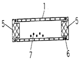
도 1(a)는 본 발명의 일실시예에 관한 세라믹무전극방전램프의 구조를 표시하고, 특히 발광관의 한쪽편을 미리 소결한 경우를 표시한 단면도.Fig. 1 (a) is a cross-sectional view showing the structure of a ceramic electrodeless discharge lamp according to an embodiment of the present invention, in particular in the case where one side of the light emitting tube is pre-sintered.
도 1(b)는 본 발명의 다른 실시예에 관한 세라믹무전극방전램프의 구조를 표시한 단면도.1 (b) is a cross-sectional view showing the structure of a ceramic electrodeless discharge lamp according to another embodiment of the present invention.
도 1(c)는 본 발명의 다른 실시예에 관한 세라믹무전극방전램프의 구조를 표시한 단면도.1C is a cross-sectional view showing the structure of a ceramic electrodeless discharge lamp in accordance with another embodiment of the present invention.
도 2는 본 발명의 일실시예에 관한 무전극방전램프의 제조방법의 일공정을 표시한 대략 표시단면도.2 is a schematic cross-sectional view showing one step of a method of manufacturing an electrodeless discharge lamp according to one embodiment of the present invention;
도 3은 본 발명의 일실시예에 관한 무전극방전램프의 제조방법의 일공정을 표시한 대략 표시단면도.3 is a schematic cross-sectional view showing one step of a method of manufacturing an electrodeless discharge lamp according to one embodiment of the present invention;
도 4는 본 발명의 일실시예에 관한 무전극방전램프의 제조방법의 일공정을 표시한 대략 표시단면도.4 is a schematic cross-sectional view showing one step of a method of manufacturing an electrodeless discharge lamp according to one embodiment of the present invention;
도 5는 본 발명의 일실시예에 관한 무전극방전램프의 제조방법의 일공정을 표시한 대략 표시단면.Fig. 5 is a schematic cross-sectional view showing one step of a method of manufacturing an electrodeless discharge lamp according to an embodiment of the present invention.
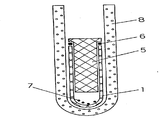
도 6(a)는 본 발명의 일실시예에 관한 무전극방전램프의 제조방법의 일공정을 표시한 대략 표시단면도.Fig. 6 (a) is a schematic cross-sectional view showing one step of the method for manufacturing an electrodeless discharge lamp according to one embodiment of the present invention.
도 6(b)는 본 발명의 다른 실시예에 관한 무전극방전램프의 제조방법의 일공정을 표시한 대략 표시단면도.Fig. 6B is a schematic cross-sectional view showing one step of the method for manufacturing an electrodeless discharge lamp according to another embodiment of the present invention.
도 7(a)는 종래의 마이크로파여기형석영벌브무전극램프의 구성의 일례를 표시한 단면도.Fig. 7 (a) is a cross-sectional view showing an example of the structure of a conventional microwave excited quartz bulb induction lamp.
도 7(b)는 종래의 유전극세라믹램프의 구성의 일례를 표시한 단면도.Fig. 7B is a cross-sectional view showing an example of the structure of a conventional electrode ceramic lamp.
도 8는 본 발명의 일실시예에 관한 무전극방전램프를 사용한 마이크로파여기무전극램프의 구성도.8 is a block diagram of a microwave excited electrodeless lamp using the electrodeless discharge lamp according to an embodiment of the present invention.
도 9는 서멧과 세라믹관을 용융유리로 밀봉한 종래의 세라믹램프를 표시한 단면도.Fig. 9 is a sectional view showing a conventional ceramic lamp in which a cermet and a ceramic tube are sealed with molten glass.
도 10은 세라믹으로 보호한 서멧과 세라믹관을 용융유리로 밀봉한 종래의 세라믹램프를 표시한 단면도.Fig. 10 is a cross-sectional view showing a conventional ceramic lamp in which a cermet protected by ceramic and a ceramic tube are sealed with molten glass.
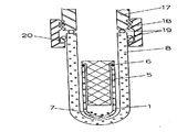
도 11은 본 발명의 다른 실시예를 표시하고, 발광관을 가동으로 하기 위한 위치조정용 모터를 설치한 예를 표시한 단면도.Fig. 11 is a sectional view showing another embodiment of the present invention and showing an example in which a position adjusting motor for activating a light emitting tube is installed;
* 도면의 주요부분에 대한 부호의 설명* Explanation of symbols for main parts of the drawings
1:세라믹관 2:세라믹발광관의 밀봉된 한쪽편1: Ceramic tube 2: Sealed one side of the ceramic light emitting tube
3:밀봉용세라믹재료의 덮개 4:밀봉용세라믹재료의 막대형상부분3: Cover of sealing ceramic material 4: Rod-shaped portion of sealing ceramic material
5:밀봉용 세라믹부재 6:밀봉용 용융유리(링)5: Sealing ceramic member 6: Sealing molten glass (ring)
7:발광재료 8:밀봉용 진공용기7: light emitting material 8: sealing vacuum container
9:국소가열장치냉각부 10:국소가열장치냉각부9: Local heating device cooling part 10: Local heating device cooling part
11:마이크로파용 도파관 12:마이크로파용 캐비티11: Waveguide for microwaves 12: Cavity for microwaves
13:발광관지지부 14:발광관회전용 모터13: Light-
15:서멧재료15: Cermet material
16:진공밀봉시에 용융유리와 진공용기가 접촉하지 않도록 방지하는 스페이서재료16: Spacer material to prevent the molten glass and the vacuum vessel from contacting during vacuum sealing
17:진공장치플랜지 18:접속용 플랜지17: Vacuum device flange 18: Flange for connection
19:밀폐용○링 20:압압판19: ○ ring for sealing 20: Pressure plate
21:밀봉부분 22:발광관지지막대21: Seal part 22: Light emitting tube support rod
23:석영벌브(발광관) 24:서멧보호용 세라믹23: Quartz bulb (light emitting tube) 24: Ceramic for cermet protection
25:마이크로파열흡수체 26:위치조절용모터25: Micro burst absorber 26: Motor for position adjustment
27:발광관(1)의 지지플랜지 28:관통구멍27: support flange of light emitting
29:방전전극29: discharge electrode
본 발명의 무전극방전램프는, 발광관과, 그 발광관속에 봉입된 적어도 발광 금속 또는 할로겐화금속과 희가스를 구비하고, 상기 발광관의 개구부는 적어도 용융유리로 진공밀봉되어 있고, 그 밀봉부는 램프발광을 위한 여기용 에너지도입용 캐비티의 외부에 형성되어 있는 것을 특징으로 한 것이다.An electrodeless discharge lamp of the present invention comprises a light emitting tube, at least a light emitting metal or a metal halide and a rare gas enclosed in the light emitting tube, and the opening of the light emitting tube is vacuum sealed at least with molten glass, and the sealing portion is a lamp. It is characterized in that formed on the outside of the excitation energy introduction cavity for light emission.
또, 본 발명의 무전극방전램프의 제조방법은, 내열성튜브속에, 미리 한쪽편이 밀폐되어 있고, 적어도 할로겐화금속 또는 발광금속을 넣은 세라믹발광관을 삽입하고, 그 발광관의 개구부를 덮개부재와 용융유리에 의해 밀폐밀봉하는데 있어서 그 밀봉부분은 다른 부분에 비해서 고온으로 하므로써 밀폐밀봉하는 것을 특징으로 한다.In the method for manufacturing an electrodeless discharge lamp of the present invention, a ceramic light emitting tube in which one side is sealed in advance in a heat resistant tube, and at least a metal halide or a light emitting metal is inserted, and the opening of the light emitting tube is melted with a lid member. In hermetically sealing by glass, the sealing part is hermetically sealed by making it high temperature compared with other parts.
이하, 본 발명의 실시형태에 대해서 도면을 참조해서 설명한다.EMBODIMENT OF THE INVENTION Hereinafter, embodiment of this invention is described with reference to drawings.
도 1(a)에 표시한 바와 같이 세라믹관(1)재료의 한쪽편(2)은 미리 소결시에 밀폐되어 있다. 다른 개구부쪽에는, 발광관이 되는 세라믹관(1)의 내경보다 큰 원판형상의 부분(3)과, 발광관의 내경보다 작은 직경의 막대형상부분(4)으로 이루어진, 볼트형상의 세라믹부재(5)가 삽입되어 있다. 상기 세라믹부재(5)의 막대형상 부분(4)의 길이와 발광관(1) 자체의 길이로부터 아크길이가 결정된다. 즉, 발광관(1) 자체의 길이로부터 막대형상부분(4)의 길이를 뺀 차가 아크길이를 결정한다. 상기 세라믹발광관(1)을 밀봉하기 위하여, 발광관(1)의 내경보다 큰 링형상의 용융 유리링(6)이 상기 세라믹부재(5)에 삽입되고, 발광관(1)의 단부에서, 발광관(1)과 세라믹막대(5)가 밀폐밀봉되어 있다.As shown in Fig. 1 (a), one side 2 of the
상기와 같은 구성을 취하면, 세라믹부재(5)의 막대형상부분(4)의 길이를 바꾸어서, 또는 발광관의 내경 및 막대형상부분(4)의 굵기를 바꿈으로써, 아크의 사이즈를 자유롭게 바꾸는 것이 가능하게 된다. 왜냐하면, 마이크로파를 사용한 무전극방전램프의 방전의 상태는, 아크방전자체가 관벽근처에 근접하여 발광관전체에 퍼지기 때문에 발광관의 사이즈자체가 거의 아크사이즈가 되기 때문이다.Taking the above structure, it is possible to freely change the size of the arc by changing the length of the rod-
또, 보호용 방전램프를 실현하기 위해서는, 쇼트아크가 필요하게 되고, 그러기 위해서는, 발광관자체를 작게하는 것이 요구된다. 그러나 종래와 같이 발광관에 석영관을 사용하면, 내열성이 부족하고, 냉각기구가 필요하게 되고, 그 때문에, 발광관에 지지막대를 붙이고 그 지지막대를 모터에 의해서 회전시켜 냉각하고 있었다. 그러나 본 발명과 같이 세라믹재료로 발광관을 구성하면, 동일파워를 입력해도, 석영관보다 균열성이 좋아지고, 회전기구를 사용하지 않아도 양호한 발광특성을 얻을 수 있다.In addition, in order to realize a protective discharge lamp, a short arc is required. In order to do so, it is required to reduce the light emitting tube itself. However, when a quartz tube is used for the light emitting tube as in the related art, heat resistance is insufficient and a cooling mechanism is required. Therefore, a supporting rod is attached to the light emitting tube, and the supporting rod is rotated by a motor and cooled. However, if the light emitting tube is made of ceramic material as in the present invention, even if the same power is input, the cracking property is better than that of the quartz tube, and good light emitting characteristics can be obtained without using a rotating mechanism.
본 실시예에서는, 세라믹발광관(1)의 한쪽편(2)을 세라믹소결시에 동시에 밀폐한 구성을 취하고 있으나, 도 1(b)에 표시한 바와 같이, 상기 개구부의 밀봉구조와 마찬가지의, 세라믹재료의 덮개(5)에 의해서 양 개구부를 밀봉하는 것도 가능하다.In this embodiment, the structure in which one side 2 of the ceramic
또 이상의 설명에서는 밀봉용 세라믹부재(5)로서 볼록형의 형상을 사용했으나, 도 1(c)에 표시한 바와 같이 세라믹판(3)을 사용해도 아무런 문제없다. 단, 발광재료를 희가스와 함께 밀폐밀봉할때에는, 미리 발광관(1)의 한쪽편은 밀봉해둘 필요가 있다.In addition, although the convex shape was used as the sealing
또, 본 실시예에서는 세라믹발광관으로서, 투광성세라믹재료를 사용했다. 그 재료로서는, 고순도 알루미나, YAG, 이트리아, 질화알루미늄 등의 고융점재료를 사용했다. 모두, 석영보다 고온에서 처리할 수 있기 때문에, 수분제거를 석영보다 향상할 수 있고, 봉입한 발광재료(7)와의 반응이 억제되어 실투(失透)현상도 억제된다.In this embodiment, a translucent ceramic material was used as the ceramic light emitting tube. As the material, high-melting point materials such as high purity alumina, YAG, yttria, and aluminum nitride were used. Since both can be processed at a higher temperature than quartz, water removal can be improved than quartz, and the reaction with the enclosed
다음에, 세라믹관을 사용해서 본 발명의 무전극방전램프를 작성하기 위한 제조방법에 대해서 도 2∼도 5를 사용해서 설명한다.Next, a manufacturing method for producing the electrodeless discharge lamp of the present invention using a ceramic tube will be described with reference to FIGS.
먼저 도 2에서 표시한 바와 같이, 발광재료(7)를 넣은 세라믹발광관(1)을, 용융용유리(6)와, 볼트형 세라믹부재(5)에 의해서 덮개를 하고, 그 덮개가 된 발광관(1)을 진공용기로서의 유리용기(8)의 속에 설치한다. 이 유리용기(8)가 본 발명의 내열튜브에 대응한다.First, as shown in FIG. 2, the ceramic
다음에, 도 3에 표시한 바와 같이 상기 유리체 진공용기(8)를 진공계에 접속하고, 진공배기를 행한다. 즉, 진공접속하기 위하여, 진공용기(8)를, 진공장치의 플랜지(17)와 접속용플랜지(18)와 ○링(19)에 의해서 밀폐한다. 접속용플랜지(18)를 조이면 압압판(20)에 의해서 ○링(19)이 압박되어 기밀접속을 할 수 있다. 접속후, 일정한 백그라운드까지 배기한 후, Ar등의 불활성가스를 소정의 압력까지 봉입한다.Next, as shown in FIG. 3, the said glass
다음에 도 4에 표시한 바와 같이 국소적으로 가열하기 위한 가열히터(9)를 밀봉부분에 설치하고, 승온에 의해 용융유리(6)를 용융시키고, 세라믹발광관(1)과 세라믹부재(5)를 접속한다. 이때, 세라믹발광재료(7)가 들어있는 부분, 즉 도면상의 아래쪼부분은, 수냉냉각, 또는 공랭(10)한다. 이에 의해, 세라믹발광재료(7)가 증발해서 발광관재료로부터 나와버리는 것을 방지할 수 있다.Next, as shown in FIG. 4, a heating heater 9 for locally heating is provided in the sealing portion, and the
또, 플랜지(17)(18)에 의해서 접속하고 있는 부분도 ○링(19)이 열에 의해 열악화하지 않도록 공랭, 수냉 등에 의해 냉각하는 편이 바람직하다.Moreover, it is more preferable to also cool the part connected by the
상기와 같은 본 발명에 의한 배기방법, 밀봉방법을 채용하면, 진공용기(8)가 국소냉각(10)의 완충제가 되고, 세라믹관(1)에 가해지는 히트쇼크를 완화할 수 있기 때문에, 세라믹관(1)이 밀봉가열중에 파손하는 것을 방지할 수 있고, 또한 할로겐화금속을 증발시키지 않고 밀폐밀봉할 수 있다.When the evacuation method and the sealing method according to the present invention as described above are employed, the
가열히터(9)로서, 칸탈(몰리브덴실리사이드히터)재료를 사용한 가열히터(9)를 사용해서, 약 2∼3mm의 국소가열에 의해 1450℃까지 승온하고, 발광재료(7)를 증발시키지 않고 밀폐밀봉할 수 있는 것을 확인할 수 있었다. 이때 사용한 진공용기(8)는 석영유리로 이루어져 있고, 내부에 넣은 세라믹발광관(1)의 재료는, 알루미나 또는 YAG를 사용해서 실험했다.As the heating heater 9, using a heating heater 9 using a cantal (molybdenum silicide heater) material, the temperature was raised to 1450 ° C by local heating of about 2 to 3 mm, and the
또, 가열해서 용융유리(6)가 용융하고, 석영유리의 진공용기(8)과 접촉하여 용착해 버리면, 냉각시에 팽창계수의 차로부터 진공용기(8)로서의 석영유리가 깨지거나, 내부의 세라믹발광관(1)을 꺼낼 수 없게 되므로, 도 5에 표시한 바와 같이, 지르코니아 또는 질화붕소로 이루어진 관(16)에 의해서 용융유리부(6)를 덮은 후, 밀폐밀봉을 행하였다. 이에 의해 용융유리(6)가 석영유리의 진공용기(8)와 직접접착하는 것을 방지할 수 있고, 세라믹발광관(1) 자체도 용이하게 꺼내는 것이 가능하게 되었다.When the
또, 도 6(a)에 표시한 바와 같이, 밀봉용 용융유리(6)를 가열하기 위하여, 히터(9)에 의해서 국소가열하는 동시에, 발광재료(7)가 존재하고 있는 장소를, 진공용기(8)마다 냉각해도 된다. 또한 냉각매체(30)로서 물 등을 사용할 수 있다. 또 도 6(b)과 같이 진공용기(8)의 바깥쪽에 마이크로파열흡수체(25)를 설치하고, 마이크로파입력하면 파워를 조정하는 것만으로도 용융유리(6)만 녹여 밀폐밀봉할 수 있다.In addition, as shown in Fig. 6 (a), in order to heat the
이 방법을 사용하면, 통상의 히터보다 국소가열할 수 있기 때문에, 발광관(1)내에 있는 발광재료(7)를 증발시키지 않고 확실히 밀폐밀봉할 수 있다.By using this method, it is possible to heat locally than a normal heater, so that the sealing material can be sealed tightly without evaporating the
다음에, 이와 같이 해서 제조된 무전극세라믹발광관을, 마이크로파에 의해서 여기발광시키는 장치의 일실시예를 도 7∼도 11을 사용하면서 설명한다.Next, an embodiment of an apparatus for exciting an electrodeless ceramic light emitting tube manufactured in this manner by excitation light emission by microwaves will be described with reference to FIGS. 7 to 11.
종래, 석영유리로 구성된 발광관(23)을, 도 6(a)와 같이 마이크로파의 캐비티(12)내에 발광관램프(23)전부를 설치하고 그것에 용접한 지지막대(22)를 외부모터(14)에 접속시켜 회전시킨다. 또 유전극(29)의 세라믹램프의 경우는, 도 6(b)와 같이, 아크근처에 밀봉재료(21)가 근접하지 않을 수 없다.Conventionally, as shown in FIG. 6 (a), the
그에 대하여, 본 발명은, 도 8과 같이 세라믹발광관(1)의 밀봉부분(21)을 마이크로파캐비티(21)밖에 설치하고, 발광부A만 캐비티(12)내에 설치하고 있으므로, 용융유리(6)의 온도상승이 억제되고, 그 결과, 세라믹관(1) 자체의 내열성을 고려하는 것만으로도 에너지투입량을 결정할 수 있다. 또한, 용융유리(6) 근처의 밀봉부분(21)온도가 억제되기 때문에, 발광재료(7)와 용융유리(6)와의 반응도 억제되고 밀봉부(21)에서의 누출에 의한 수명불량특성도 개선된다.In contrast, in the present invention, since the sealing
따라서, 이 실시예와 같은 마이크로파투입의 구조를 채용할 경우에는, 도 9에 표시한 바와 같이, 종래의 서멧(15)과 세라믹관(1)을 용융유리(6)에 의해서 밀봉해서 밀봉부분(21)을 완성시키는 구성도 가능하게 된다.Therefore, when adopting the structure of microwave injection as in this embodiment, as shown in Fig. 9, the
또한, 도 10과 같이 서멧(15)이 아크에 노출되는 부분을 세라믹막대(24)에 의해서 보호한 구성을 취해주면, 발광재료(7)와 서멧(15)과의 반응을 억제하는 것이 가능하게 된다.In addition, as shown in FIG. 10, if the
또, 도 11과 같은 구 성을 채용하면, 발광관(1)의 위치를 용이하게 조정할 수 있다. 위치조정이 가능하면, 발광관(1)에의 에너지입력의 매칭의 조정을 할 수 있어 발광강도의 최적화를 할 수 있다. 또, 센서를 이용해서 그 발광에 대응한 전기 신호 또는 발광강도를 모니터하고 있으면, 그 강도의 최대가 되는 퇴적의 위치를 확인할 수 있다. 따라서 위치조정용 모터(26)와, 모니터장치와 연동시켜주면, 용이하게 위치조정이 가능하게 된다. 이것을 행하기 위하여, 도 11과 같이 발광관(1)을 지지하기 위하여 마이크로파용 캐비티(12)에 플랜지(27)를 설치하여 발광관(1)이 움직이지 않도록 한다. 또, 발광관(1)의 지지플랜지(27)의 관통구멍(28)의 크기를, 입력마이크로파가 외부에 누출되지 않도록 조정한다. 완전히 차단하지는 것은 곤란하나, 1% 이하로 억제하는 것은 가능하다. 또 생활속에 램프의 상태가 변화하므로, 발광관(1)의 최적위치가 변해버린다. 이와 같이 최적설치위치가 변화했다해도, 도 11과 같이 위치를 변경할 수 있도록 해두면, 에너지의 입력상황에 따라서 대처할 수 있다.In addition, if the configuration shown in Fig. 11 is adopted, the position of the
이상의 설명에서는 마이크로파입력의 경우를 예로들어서 설명했으나, 에너지 입력을 자장 또는 전계에 의해서 입력한 경우에도 마찬가지의 것을 적용할 수 있다.In the above description, the case of the microwave input has been described as an example, but the same applies to the case where the energy input is input by a magnetic field or an electric field.
본 발명에 의하면, 세라믹재료를 사용한 무전극방전램프의 제조가 용이하게 된다. 석영의 대신에 세라믹재료를 사용함으로써, 내열성이 향상하고, 냉각기구에 여유가 생긴다. 따라서, 발광관자체도 작게할 수 있고, 점광원화에 유용하다. 또, 본 발명에 의한 제조법에 의하면, 종래부터의 서멧을 개재해서 유도가열을 사용하지 않아도 세라믹의 밀폐밀봉이 가능하게 된다.According to the present invention, the electrodeless discharge lamp using the ceramic material can be easily manufactured. By using a ceramic material instead of quartz, heat resistance improves, and a cooling mechanism is provided. Therefore, the light emitting tube itself can be made small, which is useful for point light source. In addition, according to the production method of the present invention, it is possible to hermetically seal the ceramic without using induction heating via a conventional cermet.
또한, 발광관재료가 알루미나 등의 세라믹재료를 사용하기 때문에, 발광물질과의 반응을 석영유리관보다 억제할 수 있고, 장수명화를 실현할 수 있다.In addition, since the light emitting tube material uses a ceramic material such as alumina, the reaction with the light emitting substance can be suppressed more than that of the quartz glass tube, and the long life can be realized.
또, 밀봉부를 마이크로파캐비티의 밖에 두면, 종래와 같이 밀봉부에, 서멧재료나, 니오브관등도 사용할 수 있다. 또한, 밀봉부분의 온도상승을 억제할 수 있기 때문에, 밀봉에서의 누출에 의한 수명특성이 개선된다.If the sealing portion is placed outside the microwave cavity, a cermet material, a niobium tube, or the like can also be used for the sealing portion in the conventional manner. In addition, since the temperature rise of the sealing portion can be suppressed, the life characteristics due to leakage in the sealing are improved.
또, 발광관의 위치를 가동할 수 있도록 해두면, 초기설정일때에도, 점등동작중이어도, 에너지의 매칭을 용이하게 할 수 있는 효과를 가진다.In addition, if the position of the light emitting tube is made movable, the effect of facilitating energy matching can be facilitated even in the initial setting even during the lighting operation.
Claims (16)
Applications Claiming Priority (2)
| Application Number | Priority Date | Filing Date | Title |
|---|---|---|---|
| JP96-9763 | 1996-01-24 | ||
| JP976396 | 1996-01-24 |
Publications (1)
| Publication Number | Publication Date |
|---|---|
| KR100269419B1 true KR100269419B1 (en) | 2000-10-16 |
Family
ID=11729320
Family Applications (1)
| Application Number | Title | Priority Date | Filing Date |
|---|---|---|---|
| KR1019970001940A KR100269419B1 (en) | 1996-01-24 | 1997-01-23 | Electrodeless discharge lamp and the manufacturing method |
Country Status (6)
| Country | Link |
|---|---|
| US (1) | US6020690A (en) |
| EP (1) | EP0786798B1 (en) |
| KR (1) | KR100269419B1 (en) |
| CN (1) | CN1105396C (en) |
| DE (1) | DE69712122T2 (en) |
| TW (1) | TW316992B (en) |
Cited By (2)
| Publication number | Priority date | Publication date | Assignee | Title |
|---|---|---|---|---|
| KR100798676B1 (en) | 2006-11-02 | 2008-01-29 | 장명기 | External electrode fluorescent lamp and method for fabricating the same |
| KR100898525B1 (en) | 2008-12-30 | 2009-05-20 | (주)에이알텍 | An induction discharge lamp module |
Families Citing this family (8)
| Publication number | Priority date | Publication date | Assignee | Title |
|---|---|---|---|---|
| US6447937B1 (en) * | 1997-02-26 | 2002-09-10 | Kyocera Corporation | Ceramic materials resistant to halogen plasma and components using the same |
| US6856092B2 (en) * | 2000-12-06 | 2005-02-15 | Itw, Inc. | Electrodeless lamp |
| GB0709343D0 (en) * | 2007-05-15 | 2007-06-27 | Ceravision Ltd | Electrodeless bulb |
| US20100102724A1 (en) * | 2008-10-21 | 2010-04-29 | Luxim Corporation | Method of constructing ceramic body electrodeless lamps |
| US8552645B2 (en) * | 2008-10-31 | 2013-10-08 | General Electric Company | Seal and leg design for ceramic induction lamp |
| JP4775461B2 (en) * | 2009-03-10 | 2011-09-21 | ウシオ電機株式会社 | Excimer lamp and excimer lamp manufacturing method |
| CN101980354A (en) * | 2010-10-14 | 2011-02-23 | 潮州市晨歌电光源有限公司 | Electric arc tube of ceramic electrodeless lamp |
| TWI585819B (en) * | 2016-10-05 | 2017-06-01 | 上一國際光電股份有限公司 | A production process of electrodeless lamp and a production process of electrodeless bulb |
Citations (1)
| Publication number | Priority date | Publication date | Assignee | Title |
|---|---|---|---|---|
| KR950034398A (en) * | 1994-03-11 | 1995-12-28 | 가노 다다오 | Electrodeless discharge lamp, electrodeless discharge lamp device, electrodeless discharge lamp lighting device and electrodeless discharge lamp |
Family Cites Families (13)
| Publication number | Priority date | Publication date | Assignee | Title |
|---|---|---|---|---|
| JPS54119783A (en) * | 1978-03-08 | 1979-09-17 | Mitsubishi Electric Corp | Electrodeless discharge lamp |
| JPS5788643A (en) * | 1980-11-22 | 1982-06-02 | Nec Home Electronics Ltd | Production of ring type fluorescent lamp |
| JPS5814447A (en) * | 1981-07-20 | 1983-01-27 | Toshiba Corp | Manufacture of curved fluorescent lamp |
| US4586115A (en) * | 1984-04-06 | 1986-04-29 | Zimmerman S Mort | Electromagnetic radio frequency excited explosion proof lighting method and system |
| US4623822A (en) * | 1984-09-26 | 1986-11-18 | Internorth, Inc. | Electrodeless discharge resonance lamp |
| JPH01236544A (en) * | 1988-03-16 | 1989-09-21 | Hitachi Ltd | Manufacture of cathode-ray tube |
| GB8821671D0 (en) * | 1988-09-02 | 1988-10-19 | Emi Plc Thorn | Discharge tube arrangement |
| US5070277A (en) * | 1990-05-15 | 1991-12-03 | Gte Laboratories Incorporated | Electrodless hid lamp with microwave power coupler |
| US5113121A (en) * | 1990-05-15 | 1992-05-12 | Gte Laboratories Incorporated | Electrodeless HID lamp with lamp capsule |
| JPH0436929A (en) * | 1990-05-31 | 1992-02-06 | Toshiba Corp | Manufacture of electron tube |
| US5150015A (en) * | 1991-04-15 | 1992-09-22 | General Electric Company | Electrodeless high intensity discharge lamp having an intergral quartz outer jacket |
| US5187412A (en) * | 1992-03-12 | 1993-02-16 | General Electric Company | Electrodeless high intensity discharge lamp |
| US5592048A (en) * | 1995-08-18 | 1997-01-07 | Osram Sylvania Inc. | Arc tube electrodeless high pressure sodium lamp |
-
1997
- 1997-01-22 EP EP97100970A patent/EP0786798B1/en not_active Expired - Lifetime
- 1997-01-22 DE DE69712122T patent/DE69712122T2/en not_active Expired - Fee Related
- 1997-01-23 US US08/787,987 patent/US6020690A/en not_active Expired - Fee Related
- 1997-01-23 TW TW086100731A patent/TW316992B/zh active
- 1997-01-23 KR KR1019970001940A patent/KR100269419B1/en not_active IP Right Cessation
- 1997-01-24 CN CN97102335A patent/CN1105396C/en not_active Expired - Fee Related
Patent Citations (1)
| Publication number | Priority date | Publication date | Assignee | Title |
|---|---|---|---|---|
| KR950034398A (en) * | 1994-03-11 | 1995-12-28 | 가노 다다오 | Electrodeless discharge lamp, electrodeless discharge lamp device, electrodeless discharge lamp lighting device and electrodeless discharge lamp |
Cited By (2)
| Publication number | Priority date | Publication date | Assignee | Title |
|---|---|---|---|---|
| KR100798676B1 (en) | 2006-11-02 | 2008-01-29 | 장명기 | External electrode fluorescent lamp and method for fabricating the same |
| KR100898525B1 (en) | 2008-12-30 | 2009-05-20 | (주)에이알텍 | An induction discharge lamp module |
Also Published As
| Publication number | Publication date |
|---|---|
| CN1164756A (en) | 1997-11-12 |
| CN1105396C (en) | 2003-04-09 |
| DE69712122D1 (en) | 2002-05-29 |
| EP0786798B1 (en) | 2002-04-24 |
| US6020690A (en) | 2000-02-01 |
| DE69712122T2 (en) | 2002-08-14 |
| TW316992B (en) | 1997-10-01 |
| EP0786798A1 (en) | 1997-07-30 |
Similar Documents
| Publication | Publication Date | Title |
|---|---|---|
| US7189131B2 (en) | High buffer gas pressure ceramic arc tube and method and apparatus for making same | |
| JP2006054195A (en) | High-pressure discharge lamp with base | |
| JP5389663B2 (en) | Ceramic burner for ceramic metal halide lamp | |
| KR100269419B1 (en) | Electrodeless discharge lamp and the manufacturing method | |
| JP5214445B2 (en) | Ceramic lamp with molybdenum-rhenium end cap, and system and method comprising the lamp | |
| US7432657B2 (en) | Ceramic lamp having shielded niobium end cap and systems and methods therewith | |
| US3628846A (en) | Method of making a vapor discharge lamp | |
| US7358666B2 (en) | System and method for sealing high intensity discharge lamps | |
| US3821587A (en) | Ceramic discharge lamp operable in air without an outer glass envelope | |
| US4746316A (en) | Method for manufacturing a luminous tube for discharge lamp | |
| JP3169846B2 (en) | Electrodeless discharge lamp and its manufacturing method | |
| EP1057211B1 (en) | Electric lamp | |
| JP2004055140A (en) | High pressure discharge lamp and lighting device | |
| JPH06290750A (en) | High pressure discharge lamp and lighting system using this discharge lamp | |
| JPS61110932A (en) | Manufacture of high pressure metal vapor discharge lamp | |
| JPH1083796A (en) | High pressure discharge lamp, lamp lighting device, and lighting system | |
| JPS62123647A (en) | Ceramic discharge lamp | |
| JPH087837A (en) | Metallic vapor discharge lamp | |
| KR20000068751A (en) | Heater utilizing microwave and bonding method using it | |
| JPH11195401A (en) | Discharge lamp | |
| JP2000331606A (en) | Manufacture of discharge lamp | |
| JP2003203569A (en) | Method of manufacturing cold cathode discharge tube | |
| JPH03233851A (en) | Vacuum discharge lamp | |
| JPH1021881A (en) | Discharge lamp | |
| JPH05334995A (en) | Metallic vapor electric discharge lamp |
Legal Events
| Date | Code | Title | Description |
|---|---|---|---|
| A201 | Request for examination | ||
| E902 | Notification of reason for refusal | ||
| E701 | Decision to grant or registration of patent right | ||
| GRNT | Written decision to grant | ||
| FPAY | Annual fee payment |
Payment date: 20060711 Year of fee payment: 7 |
|
| LAPS | Lapse due to unpaid annual fee |