KR100237694B1 - Magnetron - Google Patents
Magnetron Download PDFInfo
- Publication number
- KR100237694B1 KR100237694B1 KR1019970044989A KR19970044989A KR100237694B1 KR 100237694 B1 KR100237694 B1 KR 100237694B1 KR 1019970044989 A KR1019970044989 A KR 1019970044989A KR 19970044989 A KR19970044989 A KR 19970044989A KR 100237694 B1 KR100237694 B1 KR 100237694B1
- Authority
- KR
- South Korea
- Prior art keywords
- magnetron
- terminal
- rod
- terminals
- anode
- Prior art date
Links
Images


Classifications
-
- H—ELECTRICITY
- H01—ELECTRIC ELEMENTS
- H01J—ELECTRIC DISCHARGE TUBES OR DISCHARGE LAMPS
- H01J23/00—Details of transit-time tubes of the types covered by group H01J25/00
- H01J23/14—Leading-in arrangements; Seals therefor
- H01J23/15—Means for preventing wave energy leakage structurally associated with tube leading-in arrangements, e.g. filters, chokes, attenuating devices
-
- H—ELECTRICITY
- H01—ELECTRIC ELEMENTS
- H01J—ELECTRIC DISCHARGE TUBES OR DISCHARGE LAMPS
- H01J2225/00—Transit-time tubes, e.g. Klystrons, travelling-wave tubes, magnetrons
- H01J2225/50—Magnetrons, i.e. tubes with a magnet system producing an H-field crossing the E-field
Landscapes
- Microwave Tubes (AREA)
Abstract
본 발명은 마그네트론에 관한 것으로, 그 목적은 터미날을 개선하여 이의 변형을 방지하는 것이다.The present invention relates to a magnetron, the object of which is to improve the terminal to prevent its deformation.
본 발명에 따른 마그네트론은 사이드로드(39)와 센터로드(38)에 각각 일단부가 결합되고 타단부는 쵸크코일(45,45a)의 단부가 용접수단에 의해 접합되는 터미날(42,42a)이 소정길이를 갖도록 연장 마련되어 외부전원이 입력되는데, 터미날(42,42a)에 길이방향으로 비드부(43)가 형성되어 있다. 따라서 터미날(42,42a)의 단면적 변화로 굽힘강성이 증대되어 쵸크코일(45,45a)을 접합하는 과정 등에서 변형되지 않아 이의 신뢰성이 향상되는 이점이 있다.The magnetron according to the present invention has one end coupled to the side rod 39 and the center rod 38, respectively, and the other end has terminals 42 and 42a having end portions of the choke coils 45 and 45a joined by welding means. It is extended to have a length and an external power source is input, and bead portions 43 are formed in the terminals 42 and 42a in the longitudinal direction. Therefore, the bending stiffness is increased due to the change in the cross-sectional area of the terminals 42 and 42a, which does not deform in the process of joining the choke coils 45 and 45a, thereby improving its reliability.
Description
본 발명은 전자렌지 등의 마이크로파 가열기기에 사용되는 마그네트론에 관한 것으로, 더욱 상세하게는 센터로드와 사이드로드의 일단부에 접속되어 외부전원이 입력되는 터미날에 관한 것이다.The present invention relates to a magnetron used in a microwave heating apparatus such as a microwave oven, and more particularly, to a terminal connected to one end of a center rod and a side rod to receive an external power source.
일반적으로 전자렌지 등에 사용되는 마그네트론은 고전압을 인가받아 음극에서 방출되는 전자가 기본파 2450 MHz 주파수를 가지는 전자군을 이루고, 이 고주파 에너지를 출력부의 안테나로드를 통해 전자렌지의 케비넷 내부로 방사함으로써, 음식물을 조리한다.In general, a magnetron used in a microwave oven is applied to a high voltage to form a group of electrons emitted from the cathode having a fundamental wave 2450 MHz frequency, by radiating this high-frequency energy into the cabinet of the microwave through the antenna rod of the output, Cook food.
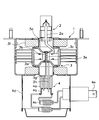
이러한 기능을 하는 마그네트론은 도 1에 도시한 바와 같이, 몸체를 이루는 요크(1) 내부에 에너지를 생성하는 양극부(3), 양극부(3)의 상부와 하부에 마이크로파를 도출하는 출력부(2)와 전원이 입력되는 입력부(4)로 크게 구별된다. 양극부(3)에는 양극실린더(3a)의 내주면에 공동공진을 이루는 복수개의 베인(3c)이 구성된다. 이 베인(3c)은 등간격으로 설치되고 양극스트랩에 의해 상호 연결되어 있으며, 중심부에 작용공간(3b)을 형성함으로써 서로 인접한 베인(3c)과의 자기유도(INDUCTANCE)와 정전용량(CAPACITANCE)으로 이루어진 공진기이다. 양극실린더(3a)의 정 중앙에는 열전자를 방출하는 나선형상의 필라멘트(3e)와 여기에 전류를 공급해주는 센터로드(3g)가 마련되어 있다. 또한 베인(3c)은 사이드로드(3h)에 의해 전류가 공급되며, 필라멘트(3e)와 베인(3c) 사이에는 약 4Kv의 전위차가 발생된다. 그리고 양극실린더(3a)의 상하부에는 페라이트 마그네트(3f)와 깔대기 형상의 자극편(3d)이 마련되어 자기에너지가 작용공간(3b)에 직속된다. 또한 베인(3c)과 결합되어 마이크로파를 외부로 방출하는 안테나로드(2a)가 자극편(3d)을 관통하고 관축을 따라 출력부(2)에 연결된다.As shown in FIG. 1, the magnetron having such a function includes an
입력부(4)에는 센터로드(3g)와 사이드로드(3h)가 끼워져 결합되는 절연통(4a)이 마련되고, 센터로드(3g)와 사이드로드(3h)에 각각 일단부가 접속된 터미날(4b)이 구성된다. 터미날(4b)은 소정의 길이를 갖도록 연장되어 있으며, 이의 타단부에는 플러그(4e)와 접속된 쵸크코일(4c)의 단부가 용접수단에 의해 접합되어 있다. 그리고 절연통(4a)과 터미날(4b), 쵸크코일(4c) 등을 감싸도록 필터박스(4d)가 마련되어 있어서, 양극실린더(3a) 내부에서 발생되는 에너지를 갖는 파가 입력부(4)를 통해 외부로 누설되는 것을 방지한다.The
이와 같이 구성된 마그네트론은 플러그(4e)와 터미날(4b)을 통해 고전압의 외부전원이 입력되면, 베인(3c)에 전류가 흐르게 되고 필라멘트(3e)에서는 전자가 방출된다. 그리고 페라이트 마그네트(3f)의 자기에너지가 작용공간(3b)에 집속 제어됨으로써, 작용공간(3b)에서 전자군과 자기에너지가 상호작용하여 기본파 2450 MHz의 주파수를 가지는 전자류 에너지를 생성한다. 그리고 이러한 고주파 에너지가 안테나로드(2a)를 통해 출력부(2)의 외부로 방사되어 음식물 등을 조리하게 된다.In the magnetron configured as described above, when a high voltage external power is input through the
이러한 마그네트론은 자동화로 생산되는데, 외부전원이 입력되는 터미날(4b)이 소정의 길이를 갖는 단순한 판상으로 이루어져 있기 때문에 제조공정상에서 약한 충격에도 변형되어 불량원인이 된다. 즉, 각각의 터미날(4b)은 앞에서 설명한 바와 같이 일단부가 사이드로드(3h)와 센터로드(3g)와 접속되어 있으며, 타단부는 일단부에서 90도 절곡 연장되며 선단에 쵸크코일(4c)이 용접수단에 의해 접합되는데, 생산라인에서 작은 충격에도 견디지 못하고 구부러지는 변형이 발생된다. 이러한 불량상태를 자동화 생산라인에서 감지하지 못함으로써, 각종 생산라인 설비 에러를 유발하고 제품불량의 원인이 된다.Such a magnetron is produced by automation. Since the
본 발명은 이러한 문제점을 해결하기 위한 것으로, 본 발명의 목적은 사이드로드와 센터로드에 각각 일단부가 결합되고 타단부는 쵸크코일의 단부가 용접수단에 의해 접합되는 터미날이 소정길이를 갖도록 연장 마련되어 외부전원이 입력되는데, 터미날에 길이방향으로 비드부를 형성하여 굽힘강성을 증대함으로써 이의 변형의 방지하는 것이다.The present invention is to solve this problem, an object of the present invention is that one end is coupled to the side rod and the center rod, respectively, and the other end is extended so that the terminal is joined to the end of the choke coil by a welding means has a predetermined length The power is input, and the bead portion is formed in the terminal in the longitudinal direction to increase the bending stiffness to prevent the deformation thereof.
도 1은 종래 마그네트론을 개략적으로 보인 단면도이다.1 is a cross-sectional view schematically showing a conventional magnetron.
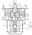
도 2는 본 발명에 따른 마그네트론의 전체적인 구조를 보인 단면도이다.2 is a cross-sectional view showing the overall structure of the magnetron according to the present invention.
도 3은 도 2의 A부 확대단면도로써, 본 발명에 따른 터미날을 확대하여 보인 것이다.3 is an enlarged cross-sectional view of a portion A of FIG. 2, showing an enlarged terminal according to the present invention.
도 4는 본 3의 B-B 선에 따른 단면도이다.4 is a cross-sectional view taken along line B-B of the third embodiment.
*도면의 주요부분에 대한 부호 설명** Description of symbols on the main parts of the drawings *
30..양극부 31..양극실린더 32..작용공간30.
33..베인 34,34a..자극편 36..필라멘트33 ..
37,37a..마그네트 38..센터로드 39..사이드로드37,37a.Magnet 38.Center load 39.Side load
41..절연통 42,42a..터미날 43..비드부41..
44..절곡부 45,45a..쵸크코일 46..플러그44. 45,45a.
이러한 목적을 달성하기 위한 본 발명은, 고주파 에너지를 생성하는 양극실린더, 양극실린더에 전류를 공급하는 센터로드와 사이드로드, 일단부가 센터로드와 사이드로드의 단부에 각각 접속되며 타단부는 플러그와 연계된 쵸크코일이 접합되는 터미날을 갖춘 마그네트론에 있어서, 터미날은 소정의 길이를 갖도록 연장되어 있으며, 굽힘강성이 증대되도록 비드부를 구비하는 것을 특징으로 한다.In order to achieve the above object, the present invention provides an anode cylinder for generating high frequency energy, a center rod and a side rod for supplying current to the anode cylinder, one end of which is connected to an end of the center rod and the side rod, and the other end is connected to a plug. In a magnetron having a terminal to which the choked coils are bonded, the terminal extends to have a predetermined length and is characterized by including a bead portion to increase bending stiffness.
이하, 본 발명에 따른 하나의 바람직한 실시예를 첨부도면을 참조하여 상세히 설명한다. 도 2는 본 발명에 따른 마그네트론의 전체적인 구조를 보인 단면도이고, 도 3과 4는 본 발명에 따른 터미날의 구조를 확대하여 보인 요부단면도이다.Hereinafter, one preferred embodiment according to the present invention will be described in detail with reference to the accompanying drawings. Figure 2 is a cross-sectional view showing the overall structure of the magnetron according to the present invention, Figures 3 and 4 is an enlarged cross-sectional view of the main portion showing the structure of the terminal according to the present invention.
본 발명에 따른 마그네트론은 이에 도시한 바와 같이, 외형 몸체를 이루는 요크(10) 내부에 기본파 2450MHz의 주파수를 가지는 전자류 에너지를 생성하는 양극부(30), 양극부(30)의 상하부에 마련되어 전자류 에너지가 외부로 방출되는 출력부(20)와 양극부(30)에 고전압의 전류를 공급하는 전원 입력부(40)로 이루어져 있다.Magnetron according to the present invention is provided in the upper and lower portions of the
양극부(30)에는 양극실린더(31)의 내주면에 등간격으로 복수개의 베인(33)이 마련된다. 베인(33)은 양극스트랩(33a)에 의해 상호 연결되어 있으며, 중심부에는 작용공간(32)을 형성한다. 작용공간(32)의 중심부에는 센터로드(38)의 단부가 축방향으로 연장 마련되며, 여기에 필라멘트(36)가 설치됨으로써 센터로드(38)를 통해 전류를 공급받아 열전자를 방출한다. 한편, 베인(33)은 사이드로드(39)에 의해 전류가 공급되며 필라멘트(36)와 베인(33) 사이의 작용공간(32)에는 약 4Kv의 전위차가 발생된다. 양극실린더(31)의 상하부에는 깔대기 형상의 자극편(34,34a)이 베인(33)의 상하측과 각각 일정간격 이격되게 마련되며, 자기에너지를 생성하는 페라이트 마그네트(37,37a)가 설치되어 있다. 이에 따라 마그네트(37,37a)의 자기에너지가 자극편(34,34a)에 의해 작용공간(32)에 집속 제어된다. 자극편은 양극실린더(31)의 상부에 설치된 상부자극편(34)과 하부에 설치된 하부자극편(34a)으로 구별되는데, 이의 중심부에는 각각 원형의 개구부가 형성되어 있으며 여기에는 필라멘트(36)로부터 상 하측 방향으로 방출되는 열전자를 차폐하기 위한 상,하부캡(35,35a)이 설치된다. 또한 베인(33)과 결합되어 마이크로파를 외부로 방출하는 안테나로드(21)가 상부자극편(35)을 관통하며 관축을 따라 출력부(20)까지 연장되어 있다. 한편, 양극실린더(31)의 외측부에는 다수의 냉각핀(31a)이 설치되어 여기에서 발생되는 열을 방출한다.The
그리고 입력부(40)에는 센터로드(38)와 사이드로드(39)가 끼워져 결합되는 세라믹 재질의 절연통(41)이 구성되고, 센터로드(38)와 사이드로드(39)의 단부에 접속되어 전원이 공급되는 터미날(42,42a)이 각각 마련된다. 판상으로 이루어진 터미날(42,42a)은 일단부가 센터로드(38)와 사이드로드(39)에 접속되며 타단부는 90도 절곡되어 소정의 길이를 갖도록 연장된다. 터미날(42,42a)의 타단부에는 소정의 곡률을 각도록 외향 밴딩된 절곡부(44)가 마련되어 쵸크코일(45,45a)의 단부가 용접수단에 의해 접합된다. 쵸크코일(45,45a)은 외부전원이 최초로 입력되는 플러그(46)와 연계되어 불요고조파가 외부로 누설되는 것을 방지한다.In addition, the
한편, 터미날(42,42a)에는 본 발명의 특징적인 요소로 굽힘 강성이 증대되도록 비드부(43)가 마련되어 있다. 비드부(43)는 도 2와 3에 도시한 바와 같이 터미날(42)에 길이방향으로 형성되어 있기 때문에, 터미날(42)의 전체적인 단면적이 변화됨으로써 외부충격에도 변형되지 않고 견디게 되며, 터미날(42)과 쵸크코일(45)의 접합이 용이하게 이루어진다. 즉, 제품의 자동화 생산라인에서 터미날(42)의 절곡부(44)와 쵸크코일(45)의 단부가 용접수단에 의해 접합되는데, 터미날(42)의 변형이 방지되어 제품불량이 발생되지 않는다.On the other hand, the
미설명부호 47은 절연통(41)과 터미날(42,42a), 쵸크코일(45,45a) 등을 감싸는 필터박스로서, 양극실린더(31)에서 생성된 에너지를 갖는 파가 입력부(40)를 통해 외부로 누설되는 것을 방지한다. 이러한 출력부(20)와 양극부(30), 입력부(40)는 산화방지와 그 효율을 높이기 위해 진공관으로 구성된다.
다음에는 이와 같이 구성된 본 발명에 따른 마그네트론의 작동을 설명한다. 먼저, 고전압의 외부전원이 플러그(46)를 통해 입력되면, 이것은 쵸크코일(45,45a)과 터미날(42,42a)을 통해 센터로드(38)와 사이드로드(39)로 공급된다. 그리고 필라멘트(36)와 양극스트랩(33a)으로 연결된 복수개의 베인(33)에 전류가 흐르게 되고, 필라멘트(36)에서는 전자가 방출된다. 아울러 양극실린더(31)의 상 하부에 마련된 페라이트 마그네트(37,37a)로부터 전달되는 자기에너지가 상,하부자극편(34,34a)에 의해 작용공간(32)에 집속 제어된다. 이에 따라 전자군과 자기에너지가 양극실린더(31)의 베인(33)과 작용공간(32)에서 상호 작용하고, 일종의 선형 운동인 사이클로이드(CYCLOID)운동을 하여 기본파 2450MHz의 주파수를 가지는 전자류 에너지를 생성한다. 이러한 고주파 에너지가 베인(33)과 접속된 안테나로드(21)를 통해 출력부(20)의 외부로 방출되어 음식물 등을 조리하게 된다.Next, the operation of the magnetron according to the present invention configured as described above will be described. First, when a high voltage external power is input through the
한편, 센터로드(38)와 사이드로드(39)에 결합되어 전원이 공급되는 터미날(42,42a)은 길이방향으로 비드부(43)가 형성되어 있기 때문에 이의 변형이 방지된다. 이에 따라 쵸크코일(45,45a)의 단부가 용이하게 접합되어 이로 인한 제품불량이 발생되지 않는다.On the other hand, since the
이상에서 상세히 설명한 바와 같이, 본 발명에 따른 마그네트론은 사이드로드와 센터로드에 각각 일단부가 결합되고 타단부는 쵸크코일의 단부가 용접수단에 의해 접합되는 터미날이 소정길이를 갖도록 연장 마련되어 외부전원이 입력되는데, 터미날에 길이방향으로 비드부를 형성하였다. 따라서 터미날의 단면적 변화로 굽힘강성이 증대됨으로써, 외부충격에도 변형되지 않아 마그네트론의 전체적인 신뢰성이 향상되는 이점이 있다.As described in detail above, the magnetron according to the present invention has one end coupled to the side rod and the center rod, respectively, and the other end is extended so that the terminal having the end of the choke coil joined by the welding means has a predetermined length. A bead portion was formed in the terminal in the longitudinal direction. Accordingly, the bending stiffness is increased by changing the cross-sectional area of the terminal, and thus, the overall reliability of the magnetron is improved since the bending rigidity is not changed.
Claims (2)
Priority Applications (1)
| Application Number | Priority Date | Filing Date | Title |
|---|---|---|---|
| KR1019970044989A KR100237694B1 (en) | 1997-08-30 | 1997-08-30 | Magnetron |
Applications Claiming Priority (1)
| Application Number | Priority Date | Filing Date | Title |
|---|---|---|---|
| KR1019970044989A KR100237694B1 (en) | 1997-08-30 | 1997-08-30 | Magnetron |
Publications (2)
| Publication Number | Publication Date |
|---|---|
| KR19990021444A KR19990021444A (en) | 1999-03-25 |
| KR100237694B1 true KR100237694B1 (en) | 2000-01-15 |
Family
ID=19520458
Family Applications (1)
| Application Number | Title | Priority Date | Filing Date |
|---|---|---|---|
| KR1019970044989A KR100237694B1 (en) | 1997-08-30 | 1997-08-30 | Magnetron |
Country Status (1)
| Country | Link |
|---|---|
| KR (1) | KR100237694B1 (en) |
-
1997
- 1997-08-30 KR KR1019970044989A patent/KR100237694B1/en not_active IP Right Cessation
Also Published As
| Publication number | Publication date |
|---|---|
| KR19990021444A (en) | 1999-03-25 |
Similar Documents
| Publication | Publication Date | Title |
|---|---|---|
| KR100237694B1 (en) | Magnetron | |
| KR100783409B1 (en) | Magnetron | |
| KR100451235B1 (en) | Input part sealing structure for magnetron | |
| KR100189101B1 (en) | Anode cylinder of magnetron | |
| KR100251565B1 (en) | Magnetron | |
| KR100268288B1 (en) | magnetron | |
| KR200150805Y1 (en) | Magnetron | |
| KR100631734B1 (en) | Antena assembly method of magnetron | |
| KR100539815B1 (en) | Gasket ring structure of magnetron | |
| KR100244312B1 (en) | Magnetron | |
| KR100518011B1 (en) | Antena cap structure of magnetron | |
| KR100617154B1 (en) | Input unit in magnetron | |
| KR100664298B1 (en) | Magnet fixing structure of magnetron | |
| KR100283778B1 (en) | Magnetron Magnetic Energy Concentrator | |
| KR100836058B1 (en) | Antenna of magnetron | |
| KR100640794B1 (en) | Connecting lead in magnetron | |
| KR20000003781U (en) | magnetron | |
| KR100480101B1 (en) | A-seal brazing structure for magnetron | |
| KR20030089323A (en) | Gasket ring eastblish structure for magnetron | |
| KR20050000759A (en) | Upper pole piece structure of magnetron | |
| KR19980010158U (en) | magnetron | |
| KR20000003407U (en) | magnetron | |
| KR20030089303A (en) | Disk structure of magnetron | |
| KR19990010071A (en) | magnetron | |
| KR19990021440A (en) | magnetron |
Legal Events
| Date | Code | Title | Description |
|---|---|---|---|
| A201 | Request for examination | ||
| E701 | Decision to grant or registration of patent right | ||
| GRNT | Written decision to grant | ||
| FPAY | Annual fee payment |
Payment date: 20060928 Year of fee payment: 8 |
|
| LAPS | Lapse due to unpaid annual fee |