KR100211069B1 - A saddle transfer device of a stone-cutter - Google Patents
A saddle transfer device of a stone-cutter Download PDFInfo
- Publication number
- KR100211069B1 KR100211069B1 KR1019970012150A KR19970012150A KR100211069B1 KR 100211069 B1 KR100211069 B1 KR 100211069B1 KR 1019970012150 A KR1019970012150 A KR 1019970012150A KR 19970012150 A KR19970012150 A KR 19970012150A KR 100211069 B1 KR100211069 B1 KR 100211069B1
- Authority
- KR
- South Korea
- Prior art keywords
- ball screw
- saddle
- stone
- fixed
- horizontal support
- Prior art date
Links
Images


Classifications
-
- B—PERFORMING OPERATIONS; TRANSPORTING
- B28—WORKING CEMENT, CLAY, OR STONE
- B28D—WORKING STONE OR STONE-LIKE MATERIALS
- B28D1/00—Working stone or stone-like materials, e.g. brick, concrete or glass, not provided for elsewhere; Machines, devices, tools therefor
- B28D1/02—Working stone or stone-like materials, e.g. brick, concrete or glass, not provided for elsewhere; Machines, devices, tools therefor by sawing
- B28D1/04—Working stone or stone-like materials, e.g. brick, concrete or glass, not provided for elsewhere; Machines, devices, tools therefor by sawing with circular or cylindrical saw-blades or saw-discs
- B28D1/044—Working stone or stone-like materials, e.g. brick, concrete or glass, not provided for elsewhere; Machines, devices, tools therefor by sawing with circular or cylindrical saw-blades or saw-discs the saw blade being movable on slide ways
-
- B—PERFORMING OPERATIONS; TRANSPORTING
- B28—WORKING CEMENT, CLAY, OR STONE
- B28D—WORKING STONE OR STONE-LIKE MATERIALS
- B28D1/00—Working stone or stone-like materials, e.g. brick, concrete or glass, not provided for elsewhere; Machines, devices, tools therefor
- B28D1/02—Working stone or stone-like materials, e.g. brick, concrete or glass, not provided for elsewhere; Machines, devices, tools therefor by sawing
- B28D1/04—Working stone or stone-like materials, e.g. brick, concrete or glass, not provided for elsewhere; Machines, devices, tools therefor by sawing with circular or cylindrical saw-blades or saw-discs
- B28D1/041—Working stone or stone-like materials, e.g. brick, concrete or glass, not provided for elsewhere; Machines, devices, tools therefor by sawing with circular or cylindrical saw-blades or saw-discs with cylinder saws, e.g. trepanning; saw cylinders, e.g. having their cutting rim equipped with abrasive particles
-
- B—PERFORMING OPERATIONS; TRANSPORTING
- B28—WORKING CEMENT, CLAY, OR STONE
- B28D—WORKING STONE OR STONE-LIKE MATERIALS
- B28D1/00—Working stone or stone-like materials, e.g. brick, concrete or glass, not provided for elsewhere; Machines, devices, tools therefor
- B28D1/02—Working stone or stone-like materials, e.g. brick, concrete or glass, not provided for elsewhere; Machines, devices, tools therefor by sawing
- B28D1/04—Working stone or stone-like materials, e.g. brick, concrete or glass, not provided for elsewhere; Machines, devices, tools therefor by sawing with circular or cylindrical saw-blades or saw-discs
- B28D1/043—Gantry type sawing machines
Abstract
본 발명은 다이아몬드 절단톱을 회전시켜 석재를 판재로 가공하는 석재 절단기에서 석재 절단수단이 고정된 새들(SADDLE)을 좌, 우직선 이송시키도록 하는 석재 절단기의 새들 이송장치에 관한 것으로 새들 이송시 맥동이 적고 속도가 일정하여 다이아몬드 절단톱의 수명이 길어지는 한편 생산성을 향상시키도록 하는 것이다.The present invention relates to a saddle feeder of a stone cutting machine for rotating the diamond cutting saw to rotate the saddle (SADDLE) fixed stone cutting means in the stone cutting machine for processing the stone to the plate left and right pulsation during saddle transfer This small and constant speed ensures longer diamond saw life and improved productivity.
이러한 본 발명은 수직지주를 타고 상하이송되는 수평지주를 구비하고 상기 수평지주를 타고 절단수단의 좌, 우측에 고정된 새들을 좌우이송시키는 석재 절단기에서, 새들의 상부에 모터의 회전방향에 따라 좌, 우회전되는 볼 스크류를 설치하고 상기 볼 스크류에는 볼 스크류 너트를 끼운 후 상기 볼 스크류 너트를 하우징으로 고정시키되 상기 너트 하우징은 수평지주에 입설된 수평고정 비임에 고정시킴으로써 이루어지며 볼 스크류 회전시 수평 고정비임에 고정된 볼 스크류 너트에 의해 볼 스크류가 좌, 우이송되며 이에따라 새들도 좌우이송되는 것이다.The present invention is a stone cutting machine having a horizontal support which is transported on a vertical support and transported to the left and right of the cutting means by the horizontal support, the stone cutter, the left in accordance with the rotation direction of the motor on the top of the birds , The ball screw is rotated to the right and the ball screw nut is inserted into the ball screw and the ball screw nut is fixed to the housing, but the nut housing is made by fixing the horizontal fixed beam placed in the horizontal support. The ball screw is moved left and right by the fixed ball screw nut, and accordingly, the saddle is also moved left and right.
Description
본 발명은 다이아몬드 절단톱을 회전시켜 석재를 판재로 가공하는 석재 절단기에서 석재 절단수단에 고정된 새들(SADDLE)을 좌, 우직선 이송시키도록 하는 석재 절단기의 새들 이송장치에 관한 것으로 새들 이송시 맥동이 적고 속도가 일정하여 다이아몬드 절단톱의 수명이 길어지는 한편 생산상을 향상시키도록 하는 것이다.The present invention relates to a saddle feeder of a stone cutter to rotate the diamond cutting saw to rotate the saddle (SADDLE) fixed to the stone cutting means in the stone cutting machine for processing the stone to the plate to the left and right pulsation during saddle transfer This small and constant speed allows the diamond saw to last longer and to improve production.
기존의 석재 절단기는 통상 4개의 수직지주가 설치되고 수직지주에는 수직지주를 타고 상, 하왕복 이송되어지는 수평지주가 설치되며 이때 수평지주의 이송동력은 수직지주 상부에 설치되어 수평지주가 수직지주를 타고 상, 하이송될 수 있게 한다.Conventional stone cutters are usually equipped with four vertical supports, and the vertical support is installed on the horizontal support to be transported up and down the vertical support, wherein the transfer power of the horizontal support is installed above the vertical support, the horizontal support is vertical Allows you to ride the statue and Haisong.
그리고 수평지주에는 수평지주를 타고 좌, 우수평 이송되는 절단수단을 설치하되 절단수단의 이송동력은 다이아몬드 절단톱이 끼워진 톱집(ASW Case) 상부에 고정되어 수평지주의 레일면을 따라 로울러를 회전시킴으로써 수평지주를 타고 절단수단이 이송되게 한다.In the horizontal support, a horizontal means is installed to cut left and right flat conveying means, but the conveying power of the cutting means is fixed to the upper part of the ASW Case in which the diamond cutting saw is inserted, thereby rotating the roller along the rail surface of the horizontal support. Allow the cutting means to be transported on the horizontal support.
이러한 적재 절단기는 절단수단을 좌, 우수평 이송시켜가며 수직지주를 타고 수평지주가 하부로 서서히 이송되게 하므로써 석재를 다이아몬드 절단 톱으로 절단하여 판재형태로 가공하게 된다.This stacking cutter transfers the cutting means to the left and the right flat, and the horizontal support is gradually transported to the lower portion by riding the vertical support so that the stone is cut into a diamond cutting saw and processed into a plate shape.
그러나 다이아몬드 절단톱이 여러개 병렬설치되는 관계로 석재 절단시 커다란 절삭저항을 받게되어 절단톱의 진동이 발생되므로 다이아몬드 절단팁이 쉽게 떨어져나가고 절단오차가 발생되어 균일한 형태의 판재를 얻을 수 없는 것이었다.However, because the diamond saws are installed in parallel in parallel, the stone is subjected to a large cutting resistance when the stone is cut, causing the saw blade to vibrate, so that the diamond cutting tip is easily detached and a cutting error occurs to obtain a uniform plate.
이러한 문제점을 해결하기 위하여 국내 실용신안 공보 93-7515 호로 절단수단의 좌, 우측으로 새들을 고정시킨 후 상기 새들을 좌, 우이송시켜가며 석재를 절단시키는 석재 절단기가 제시되어 있으나 상기 석재 절단기는 새들의 상부에 래크기어를 구비시키고 수직 지주를 타고 상하이송되는 피니언을 상기 래크기어에 치합시킴으로써 새들을 좌, 우 이송시키게 되어 있다.In order to solve this problem, the Korean Utility Model Publication No. 93-7515 fixes the birds to the left and right sides of the cutting means, and then the stone cutters for cutting the stones while feeding the birds left and right have been proposed. A rack gear is provided on the upper part of the gear, and the pinion, which is transported in a vertical post, is fitted to the rack gear to move the birds left and right.
그러나 래크기어와 피니언을 이용하여 새들을 좌, 우 이송시키는 방식은 미세한 이동을 기대하기 어렵고 이송속도가 느리며 특히 절단수단에 걸리는 부하에 영향을 받아 부하에 따라 이송속도가 변화되는 문제점이 발생되는 한편 석재 절단시 맥동현상을 완전히 잡아주지 못하게 되어 원활한 석재절단을 기대하기 어렵고 다이아몬드 절삭팁이 떨어져 나가는 것도 방지해 주기 어려운 것이다.However, the method of conveying the birds left and right by using the rack gear and pinion is difficult to expect the fine movement, and the feeding speed is slow. Especially, the feeding speed is changed depending on the load on the cutting means. It is difficult to expect smooth stone cutting because it is not able to completely catch the pulsation phenomenon when cutting the stone, and it is difficult to prevent the diamond cutting tip from falling off.
본 발명은 볼 스크류를 이용하여 석재 절단기의 새들은 좌, 우수평 이송시키도록 하므로써 맥동이 적어지고 부하에 관계없이 이송속도가 일정하며 미세한 이송이 가능하여 다이아몬드 절삭팁이 떨어져 나감을 방지하며 생산성을 향상시키도록 한 것이다.The present invention by using the ball screw to make the saddle of the stone cutter to the left, even flat conveying is less pulsation, the feed rate is constant regardless of the load, fine feeding is possible to prevent the diamond cutting tip falling off and productivity It is to improve.
이러한 본 발명은 수직지주를 타고 상하이송되는 수평지주를 구비하고 상기 수평지주를 타고 절단수단의 좌, 우측에 고정된 새들을 좌우이송시키는 석재 절단기에 있어서, 새들의 상부에 모터의 회전방향에 따라 좌, 우회전되는 볼 스크류를 설치하고 상기 볼 스크류에는 볼 스크류 너트를 끼운 후 상기 볼 스크류 너트를 너트 하우징으로 고정시키되 상기 너트 하우징은 수평지주에 입설된 수평고정 비임에 고정시킴으로써 볼 스크류 회전시 수평 고정비임에 고정된 볼 스크류 너트에 의해 볼 스크류가 좌, 이송되며 이에따라 새들도 좌우이송되도록 한 것이다.The present invention is a stone cutting machine having a horizontal support to be transported in a vertical support and transport the birds fixed to the left and right of the cutting means in the horizontal support, according to the rotation direction of the motor on the top of the birds Install the ball screw rotated left and right, and insert the ball screw nut to the ball screw, and then fix the ball screw nut to the nut housing, but the nut housing is fixed to the horizontal fixed beam placed in the horizontal support horizontal fixed ratio when rotating the ball screw The ball screw is moved left and right by means of the ball screw nut fixedly, so that the saddle is also moved left and right accordingly.
즉 본 발명은 새들의 상부에 설치된 볼 스크류를 회전시키게 되고 볼 스크류에 체결된 볼 스크류 너트를 수평지주에 고정시킴으로써 볼 스크류 회전시 새들이 수평지주 상부에서 좌, 우이송되어 절단수단에 의한 석재절단이 이루어지는 것으로 볼 스크류 대신에 일반 스크류를 사용하여도 무방하다.That is, the present invention rotates the ball screw installed on the top of the saddle and by fixing the ball screw nut fastened to the ball screw in the horizontal support when the ball screw rotates left and right at the top of the horizontal support is cut stone by cutting means In this case, a general screw may be used instead of the ball screw.
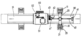
제1도는 본 발명 석재 절단기의 사시도.1 is a perspective view of a stone cutting machine of the present invention.
제2도는 본 발명 석재 절단기의 일부절결 정면도.2 is a partially cut-away front view of the stone cutting machine of the present invention.
제3도는 본 발명 석재 절단기의 일부절경 평면도.3 is a partial plan view of the stone cutting machine of the present invention.
제4도는 본 발명의 요부측면도.4 is a side view of main parts of the present invention.
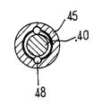
제5도는 본 발명 볼 스크류의 정단면도.Figure 5 is a front sectional view of the ball screw of the present invention.
제6도는 본 발명 볼 스크류의 측단면도.6 is a side cross-sectional view of the ball screw of the present invention.
* 도면의 주요부분에 대한 부호의 설명* Explanation of symbols for main parts of the drawings
10,11 : 수직지주 12 : 이송나사축10,11: Vertical holding 12: Feed screw shaft
20 : 수평지주 21 : 나사고정구20: horizontal support 21: screw fasteners
24 : 새들지지구 30,31 : 새들24:
40 : 볼스크류 41,41' : 브라켓트40:
42 : 모터 44 : 너트하우징42: motor 44: nut housing
45 : 볼스크류너트 47 : 귀환구45: ball screw nut 47: return port
48 : 볼베어링 50 : 절단수단48: ball bearing 50: cutting means
53 : 다이아몬드 절단톱53: diamond cutting saw
제1도는 본 발명의 사시도이고 제2도는 본 발명의 일부절결 정면도이며 제3도는 본 발명의 일부절결 평면도이고 제4도는 본 발명의 요부 측면도로써 콘크리트 타설된 고정 구조물(1)상부에는 고정부재(2)가 볼트로 결합되고 상기 고정부재(2)의 양측면에 각각 한 개씩 도합 4개의 수직지주(10)(11)를 볼트 고정시킨다.1 is a perspective view of the present invention and FIG. 2 is a partially cutaway front view of the present invention, and FIG. 3 is a partially cutaway plan view of the present invention, and FIG. 4 is a side view of the main portion of the present invention. 2) is bolted together and bolts the four
전, 후방향으로 대향된 수직지주(10)(11)에는 하나씩의 수평지주(20)를 끼우되 수평지주(20)가 수직지주(10)(11)에 외삽된 형태로 결합한다.The front and rear
수직지주(10)(11)의 상부에는 수평바(3)를 연결 고정시키고 수평바(3) 상부에는 모터(4)를 고정시키되 상기 모터(4)의 회전동력은 동력 전달축(5)을 통하여 수직지주(10)(11)상부에 고정시킨 기어 결합구(6)에 전달되게 하고 베벨기어 등으로 이루어진 기어 결합구(6)에는 모터(4)의 동력을 수직지주(10)의 외측내부에 설치된 이송 나사축(12)에 전달되게 설치한다.The
즉 모터(4)회전은 동력 전달축(5)에서, 기어 결합구(6)를 거쳐 이송 나사축(12)을 회전시키게 되고 상기 이송나사축(12)의 회전은 수평지주(20)를 상, 하 이송시키는데 사용된다.That is, the rotation of the motor 4 rotates the
상기 이송나사축(12)에는 나사 고정구(21)가 끼워지고 상기 나사 고정구(21)는 수평지주(20)에 고정시킴으로써 수평지주(20)가 이송 나사축(12)의 회전방향에 따라 상, 하이송되어진다.The
수평지주(20)에는 각각 일정거리를 두고 V자형의 슬라이드 홈(22)이 형성되고 상기 슬라이드 홈(22)에 새들(30)의 하부에 형성시킨 슬라이더(32)가 끼워지게 새들(30)을 수평지주(20)에 결합한다.V-
이때 새들(30)(32)은 절단수단(50)의 좌, 우측에 각각 볼트결합되어 새들(30)(31)과 절단수단(50)을 하나의 몸체로 형성시킨다.At this time, the
그리고 슬라이드 홈(22)이 파여진 수평지주(20)내측에는 힌지(23)로 고정된 새들 지지구(24)를 설치하여 새들(30)의 슬라이더(32)를 새들 지지구(24)가 받쳐줄 수 있도록 하되 새들 지지구(24)에도 슬라이드 홈(22)과 같은 형태로 V자형 홈을 형성시켜 새들(30)이 부드럽게 좌, 이송되게 한다.In addition, the
여기서 새들 지지구(24)는 힌지(23)에 의해 좌, 우 유동되어가며 슬라이더 (32)를 받쳐주게 되므로 절단수단(50)에 새들(30)(31)이 일직선으로 결합되지 못하고 약간의 경사각을 갖더라도 이를 보정하여 가며 받쳐주게 된다.Here, the
절단수단(50)은 새들(30)(31)의 중앙에 결합되고 상부에 고정된 모터(51)의 회전동력이 감속기(52)를 거쳐 다이아몬드 절단톱(53)을 회전시키게 구성되고 상기 다이아몬드 절단톱(53)은 복수개를 연설시킨 것으로 공지된 내용이다.
절단수단(50)에 결합된 새들(30)의 상부에는 볼 스크류(40)를 길이방향으로 설치하되 볼 스크류(40)의 양측은 베어링이 내장된 브라켓트(41)(41')에 의해 고정시키고 볼 스크류(40)의 일측에서 모터(42)의 회전동력을 V벨트(43)로 전달받을 수 있도록 설치한다.On the upper part of the
상기 볼 스크류(40)에도 제4도와 제5도에 도시된 바와 가팅 볼 스크류 너트(45)가 체결되고 상기 볼 스크류 너트(45)는 너트 하우징(44)에 의해 고정되며 상기 너트 하우징(44)은 수평지주(20)의 상부에 고정시킨 수평 고정비임(25)에 결합 고정시킴으로써 볼 스크류(40)회전시 볼 스크류 너트(45)가 너트 하우징(44)에 끼워져 수평 고정비임(25)에 고정되므로 새들(30)이 좌, 우 이송되게 된다.The
여기서 볼 스크류 너트(45)에 귀환구(47)가 형성되어 볼 스크류(40)회전시 내장된 볼 베어링(48)이 귀환구(47)를 타고 귀환 되도록 한다.Here, the
한편 본 발명에서 볼 스크류(40)를 사용하지 않고 일반 스크류를 사용하여도 무방하며 회전운동을 직선 왕복운동으로 변환시켜 주면 된다.Meanwhile, in the present invention, a general screw may be used without using the
이러한 구성의 본 발명에서 석재 절단기는 수평지주(20)를 하강시켜 다이아몬드 절단톱(53)이 석재에 닿을 수 있는 상태에서 다이아몬드 절단톱(53)을 회전시켜 가며 새들(30)을 좌, 우 이송시킴으로써 석재를 절단하게되고 석재 절단 상태에 따라 수평지주(20)를 서서히 하강시키게 된다.Stone cutting machine in the present invention of such a configuration by lowering the
여기서 수평지주(20)의 하강 또는 상승은 모터(4)의 회전방향을 전환시켜 이송나사축(12)을 회전시킴에 따라 나사 고정구(21)가 고정된 수평지주(20)가 상, 하이송된다.Here, the
절단수단(50)에서는 모터(51)의 회전을 감속기(52)로 감속시켜 다이아몬드 절단톱(53)을 회전시키게 되고 상기 다이아몬드 절단톱(53)은 복수개를 병렬로 결합시켜 한 번에 여러개의 판재를 절단해 낼 수 있게 한다.In the cutting means 50, the rotation of the
다음으로 새들(30)은 좌우이송시키는 동작을 살펴본다.Next, the
먼저 새들(30)은 하부에 V자형 슬라이더(32)가 형성되고 상기 슬라이더(32)가 수평지주(20)의 슬라이드 홈(22)에 끼워지게 결합하되 수평지주(20)내측에서 힌지(23)로 고정된 새들 지지구(24)에 의해 받쳐질 수 있도록 결합한다.First, the
따라서 새들(30)은 좌, 우이송시 슬라이더(32)가 슬라이드 홈(22)과 새들 지지구(24)를 타고 좌, 우 이송되게 된다.Therefore, the
새들(30)은 이송시키기 위해서는 모터(42)를 회전시켜 모터(42)의 회전동력이 V벨트(43)를 통하여 볼 스크류(40)를 회전시키도록 한다.The
여기서 볼 스크류(40)는 양측이 브라켓트(41)(41')에 의해 새들(30)상부 중앙에 길이방향으로 고정되고 볼 스크류(40)에는 볼 스크류 너트(45)가 끼워져 너트 하우징(44)으로 고정되며 너트 하우징(44)의 수평지주(20)에 입설되 수평 고정비임(25)에 고정된다.Here, the
따라서 볼 스크류(40)가 회전되면 볼 스크류 너트(45)가 고정된 관계로 새들930)이 좌측 또는 우측으로 이송하게 된다.Accordingly, when the
이때 볼 스크류(40)와 볼 스크류 너트(45)사이에는 제5도에 도시된 바와 같이 수많은 볼 베어링(48)이 내장되어 볼 스크류(40)회전에 따라 볼 베어링(48)이 귀환구(47)를 통해 이송되며 볼 스크류(40)가 회전되어진다.At this time, a number of
여기서 볼 스크류(40)는 먼지 등의 이물질이 묻지 않도록 커버를 씌워주게 된다.The ball screw 40 is covered with a cover to prevent foreign matter such as dust.
이같이 새들(30)은 볼 스크류(40)의 회전방향에 의해 좌, 우이송되게 되고 볼 스크류(40)는 볼 베어링(48)의 이송과 함께 이루어지므로 다이아몬드 절단톱(53)에 걸리는 부하에 관계없이 새들(30)의 좌우이송 속도가 균일해지고 래크기어와 피니언 결합방식에 의한 이송보다 맥동이 적어지게 된다.As such, the
특히 새들(30)의 이송속도가 일정하여 다이아몬드 절삭팁이 떨어져나가는 경우가 최소화 된다.In particular, the feed rate of the
본 발명은 볼 스크류 방식에 의한 새들이 좌, 우 이송이 이루어져 다이아몬드 절삭팁이 떨어짐이 방지되어 수명을 연장시키는 한편 특히 새들 이송시 맥동이 적어지는 효과가 제공된다.The present invention is provided by the ball screw method to the left, right feed is prevented fall of the diamond cutting tip is extended to extend the life while providing a particularly effective pulsation during saddle transport.
Claims (4)
Priority Applications (1)
| Application Number | Priority Date | Filing Date | Title |
|---|---|---|---|
| KR1019970012150A KR100211069B1 (en) | 1997-03-26 | 1997-03-26 | A saddle transfer device of a stone-cutter |
Applications Claiming Priority (1)
| Application Number | Priority Date | Filing Date | Title |
|---|---|---|---|
| KR1019970012150A KR100211069B1 (en) | 1997-03-26 | 1997-03-26 | A saddle transfer device of a stone-cutter |
Publications (2)
| Publication Number | Publication Date |
|---|---|
| KR19980075812A KR19980075812A (en) | 1998-11-16 |
| KR100211069B1 true KR100211069B1 (en) | 1999-07-15 |
Family
ID=19501791
Family Applications (1)
| Application Number | Title | Priority Date | Filing Date |
|---|---|---|---|
| KR1019970012150A KR100211069B1 (en) | 1997-03-26 | 1997-03-26 | A saddle transfer device of a stone-cutter |
Country Status (1)
| Country | Link |
|---|---|
| KR (1) | KR100211069B1 (en) |
Cited By (2)
| Publication number | Priority date | Publication date | Assignee | Title |
|---|---|---|---|---|
| CN103862580A (en) * | 2014-04-02 | 2014-06-18 | 青岛农业大学 | Full-automatic marble flame machining device |
| CN106799793A (en) * | 2017-02-23 | 2017-06-06 | 李淑娟 | A kind of fixture for cutting marble |
Families Citing this family (1)
| Publication number | Priority date | Publication date | Assignee | Title |
|---|---|---|---|---|
| KR100667365B1 (en) * | 2005-12-09 | 2007-01-10 | (주)월드비젼 | Concrete structure body cutting system |
-
1997
- 1997-03-26 KR KR1019970012150A patent/KR100211069B1/en not_active IP Right Cessation
Cited By (2)
| Publication number | Priority date | Publication date | Assignee | Title |
|---|---|---|---|---|
| CN103862580A (en) * | 2014-04-02 | 2014-06-18 | 青岛农业大学 | Full-automatic marble flame machining device |
| CN106799793A (en) * | 2017-02-23 | 2017-06-06 | 李淑娟 | A kind of fixture for cutting marble |
Also Published As
| Publication number | Publication date |
|---|---|
| KR19980075812A (en) | 1998-11-16 |
Similar Documents
| Publication | Publication Date | Title |
|---|---|---|
| JP6243388B2 (en) | Band saw machine | |
| KR100211069B1 (en) | A saddle transfer device of a stone-cutter | |
| CA2492509C (en) | A stone slicer | |
| CN109203085A (en) | The preferred truncation adjustable cast iron planes production line of high speed | |
| US5238339A (en) | Machine tool for working flat workpieces | |
| KR200174164Y1 (en) | Stone cutting machine | |
| KR100627132B1 (en) | Apparatus for a groove joint of a wood-carving building | |
| CN215698303U (en) | Numerical control planer-type milling machine that can automatic chip removal | |
| KR200174163Y1 (en) | Stone cutting machine | |
| CN210850626U (en) | Cutter dust keeper of four sides planer | |
| US3662795A (en) | Apparatus for forming stakes, bridging and the like | |
| KR100663764B1 (en) | A chain | |
| KR200373803Y1 (en) | Board Sawing Machine | |
| KR930007515Y1 (en) | Cutting device | |
| CN114684547B (en) | Workpiece conveying device with transverse binding feet and conveying method | |
| CN217192597U (en) | Automatic feeder of oil-driven lathe | |
| CN220614525U (en) | Sawing machine for loose stone | |
| CN211967781U (en) | Stable timber planer | |
| CN218464621U (en) | Novel many models charging equipment | |
| KR100560195B1 (en) | Apparatus for a groove joint of a wood-carving building | |
| KR200231346Y1 (en) | Stone cutting device for base rock | |
| KR200354745Y1 (en) | Apparatus for a groove joint of a wood-carving building | |
| KR200260161Y1 (en) | A have material transfer device to high speed cutting machine | |
| CN212946911U (en) | Guide feeding device capable of centering and double-end-face grinding machine thereof | |
| CN218425979U (en) | Little bits are dug and are sawed board machine |
Legal Events
| Date | Code | Title | Description |
|---|---|---|---|
| A201 | Request for examination | ||
| E701 | Decision to grant or registration of patent right | ||
| GRNT | Written decision to grant | ||
| FPAY | Annual fee payment |
Payment date: 20020427 Year of fee payment: 4 |
|
| LAPS | Lapse due to unpaid annual fee |