JPWO2012160661A1 - Battery and manufacturing method thereof - Google Patents
Battery and manufacturing method thereof Download PDFInfo
- Publication number
- JPWO2012160661A1 JPWO2012160661A1 JP2011542610A JP2011542610A JPWO2012160661A1 JP WO2012160661 A1 JPWO2012160661 A1 JP WO2012160661A1 JP 2011542610 A JP2011542610 A JP 2011542610A JP 2011542610 A JP2011542610 A JP 2011542610A JP WO2012160661 A1 JPWO2012160661 A1 JP WO2012160661A1
- Authority
- JP
- Japan
- Prior art keywords
- unit cell
- battery
- case
- electrode layer
- fluid
- Prior art date
- Legal status (The legal status is an assumption and is not a legal conclusion. Google has not performed a legal analysis and makes no representation as to the accuracy of the status listed.)
- Granted
Links
Images
Classifications
-
- H—ELECTRICITY
- H01—ELECTRIC ELEMENTS
- H01M—PROCESSES OR MEANS, e.g. BATTERIES, FOR THE DIRECT CONVERSION OF CHEMICAL ENERGY INTO ELECTRICAL ENERGY
- H01M50/00—Constructional details or processes of manufacture of the non-active parts of electrochemical cells other than fuel cells, e.g. hybrid cells
- H01M50/20—Mountings; Secondary casings or frames; Racks, modules or packs; Suspension devices; Shock absorbers; Transport or carrying devices; Holders
- H01M50/258—Modular batteries; Casings provided with means for assembling
-
- H—ELECTRICITY
- H01—ELECTRIC ELEMENTS
- H01M—PROCESSES OR MEANS, e.g. BATTERIES, FOR THE DIRECT CONVERSION OF CHEMICAL ENERGY INTO ELECTRICAL ENERGY
- H01M10/00—Secondary cells; Manufacture thereof
- H01M10/04—Construction or manufacture in general
- H01M10/0481—Compression means other than compression means for stacks of electrodes and separators
-
- H—ELECTRICITY
- H01—ELECTRIC ELEMENTS
- H01M—PROCESSES OR MEANS, e.g. BATTERIES, FOR THE DIRECT CONVERSION OF CHEMICAL ENERGY INTO ELECTRICAL ENERGY
- H01M50/00—Constructional details or processes of manufacture of the non-active parts of electrochemical cells other than fuel cells, e.g. hybrid cells
- H01M50/20—Mountings; Secondary casings or frames; Racks, modules or packs; Suspension devices; Shock absorbers; Transport or carrying devices; Holders
- H01M50/202—Casings or frames around the primary casing of a single cell or a single battery
-
- H—ELECTRICITY
- H01—ELECTRIC ELEMENTS
- H01M—PROCESSES OR MEANS, e.g. BATTERIES, FOR THE DIRECT CONVERSION OF CHEMICAL ENERGY INTO ELECTRICAL ENERGY
- H01M10/00—Secondary cells; Manufacture thereof
- H01M10/05—Accumulators with non-aqueous electrolyte
- H01M10/052—Li-accumulators
-
- H—ELECTRICITY
- H01—ELECTRIC ELEMENTS
- H01M—PROCESSES OR MEANS, e.g. BATTERIES, FOR THE DIRECT CONVERSION OF CHEMICAL ENERGY INTO ELECTRICAL ENERGY
- H01M2220/00—Batteries for particular applications
- H01M2220/20—Batteries in motive systems, e.g. vehicle, ship, plane
-
- H—ELECTRICITY
- H01—ELECTRIC ELEMENTS
- H01M—PROCESSES OR MEANS, e.g. BATTERIES, FOR THE DIRECT CONVERSION OF CHEMICAL ENERGY INTO ELECTRICAL ENERGY
- H01M50/00—Constructional details or processes of manufacture of the non-active parts of electrochemical cells other than fuel cells, e.g. hybrid cells
- H01M50/10—Primary casings; Jackets or wrappings
- H01M50/102—Primary casings; Jackets or wrappings characterised by their shape or physical structure
- H01M50/103—Primary casings; Jackets or wrappings characterised by their shape or physical structure prismatic or rectangular
-
- H—ELECTRICITY
- H01—ELECTRIC ELEMENTS
- H01M—PROCESSES OR MEANS, e.g. BATTERIES, FOR THE DIRECT CONVERSION OF CHEMICAL ENERGY INTO ELECTRICAL ENERGY
- H01M50/00—Constructional details or processes of manufacture of the non-active parts of electrochemical cells other than fuel cells, e.g. hybrid cells
- H01M50/10—Primary casings; Jackets or wrappings
- H01M50/14—Primary casings; Jackets or wrappings for protecting against damage caused by external factors
-
- H—ELECTRICITY
- H01—ELECTRIC ELEMENTS
- H01M—PROCESSES OR MEANS, e.g. BATTERIES, FOR THE DIRECT CONVERSION OF CHEMICAL ENERGY INTO ELECTRICAL ENERGY
- H01M50/00—Constructional details or processes of manufacture of the non-active parts of electrochemical cells other than fuel cells, e.g. hybrid cells
- H01M50/10—Primary casings; Jackets or wrappings
- H01M50/183—Sealing members
- H01M50/186—Sealing members characterised by the disposition of the sealing members
-
- H—ELECTRICITY
- H01—ELECTRIC ELEMENTS
- H01M—PROCESSES OR MEANS, e.g. BATTERIES, FOR THE DIRECT CONVERSION OF CHEMICAL ENERGY INTO ELECTRICAL ENERGY
- H01M50/00—Constructional details or processes of manufacture of the non-active parts of electrochemical cells other than fuel cells, e.g. hybrid cells
- H01M50/20—Mountings; Secondary casings or frames; Racks, modules or packs; Suspension devices; Shock absorbers; Transport or carrying devices; Holders
- H01M50/218—Mountings; Secondary casings or frames; Racks, modules or packs; Suspension devices; Shock absorbers; Transport or carrying devices; Holders characterised by the material
- H01M50/22—Mountings; Secondary casings or frames; Racks, modules or packs; Suspension devices; Shock absorbers; Transport or carrying devices; Holders characterised by the material of the casings or racks
- H01M50/222—Inorganic material
- H01M50/224—Metals
-
- Y—GENERAL TAGGING OF NEW TECHNOLOGICAL DEVELOPMENTS; GENERAL TAGGING OF CROSS-SECTIONAL TECHNOLOGIES SPANNING OVER SEVERAL SECTIONS OF THE IPC; TECHNICAL SUBJECTS COVERED BY FORMER USPC CROSS-REFERENCE ART COLLECTIONS [XRACs] AND DIGESTS
- Y02—TECHNOLOGIES OR APPLICATIONS FOR MITIGATION OR ADAPTATION AGAINST CLIMATE CHANGE
- Y02E—REDUCTION OF GREENHOUSE GAS [GHG] EMISSIONS, RELATED TO ENERGY GENERATION, TRANSMISSION OR DISTRIBUTION
- Y02E60/00—Enabling technologies; Technologies with a potential or indirect contribution to GHG emissions mitigation
- Y02E60/10—Energy storage using batteries
-
- Y—GENERAL TAGGING OF NEW TECHNOLOGICAL DEVELOPMENTS; GENERAL TAGGING OF CROSS-SECTIONAL TECHNOLOGIES SPANNING OVER SEVERAL SECTIONS OF THE IPC; TECHNICAL SUBJECTS COVERED BY FORMER USPC CROSS-REFERENCE ART COLLECTIONS [XRACs] AND DIGESTS
- Y02—TECHNOLOGIES OR APPLICATIONS FOR MITIGATION OR ADAPTATION AGAINST CLIMATE CHANGE
- Y02P—CLIMATE CHANGE MITIGATION TECHNOLOGIES IN THE PRODUCTION OR PROCESSING OF GOODS
- Y02P70/00—Climate change mitigation technologies in the production process for final industrial or consumer products
- Y02P70/50—Manufacturing or production processes characterised by the final manufactured product
-
- Y—GENERAL TAGGING OF NEW TECHNOLOGICAL DEVELOPMENTS; GENERAL TAGGING OF CROSS-SECTIONAL TECHNOLOGIES SPANNING OVER SEVERAL SECTIONS OF THE IPC; TECHNICAL SUBJECTS COVERED BY FORMER USPC CROSS-REFERENCE ART COLLECTIONS [XRACs] AND DIGESTS
- Y10—TECHNICAL SUBJECTS COVERED BY FORMER USPC
- Y10T—TECHNICAL SUBJECTS COVERED BY FORMER US CLASSIFICATION
- Y10T29/00—Metal working
- Y10T29/49—Method of mechanical manufacture
- Y10T29/49002—Electrical device making
- Y10T29/49108—Electric battery cell making
- Y10T29/4911—Electric battery cell making including sealing
Landscapes
- Chemical & Material Sciences (AREA)
- Chemical Kinetics & Catalysis (AREA)
- Electrochemistry (AREA)
- General Chemical & Material Sciences (AREA)
- Engineering & Computer Science (AREA)
- Manufacturing & Machinery (AREA)
- Secondary Cells (AREA)
- Gas Exhaust Devices For Batteries (AREA)
- Battery Mounting, Suspending (AREA)
- Primary Cells (AREA)
Abstract
本発明は、素電池を均一に加圧することが可能な電池及びその製造方法を提供することを主目的とする。本発明は、正極層、負極層、及び、正極層と負極層との間に配設された電解質層を有する積層体、並びに、該積層体を収容する素電池ケースを備えた素電池と、該素電池を収容する外装電池ケースとを具備し、素電池ケースの外側且つ外装電池ケースの内側に、素電池を加圧可能な流体が充填され、素電池ケースの封止口が外装電池ケースの外側にある電池とし、素電池を作製する工程と、素電池ケースの封止口が外装電池ケースの外側に配置されるようにしながら素電池を外装電池ケース内に収容する工程と、素電池ケースの封止口を開けた状態で、素電池ケースの外側且つ外装電池ケースの内側に流体を注入する工程と、を順に有する、電池の製造方法とする。The main object of the present invention is to provide a battery that can uniformly pressurize the unit cell and a method for manufacturing the same. The present invention includes a positive electrode layer, a negative electrode layer, a laminate having an electrolyte layer disposed between the positive electrode layer and the negative electrode layer, and a unit cell including a unit cell case containing the laminate, An external battery case that accommodates the unit cell, and a fluid that can pressurize the unit cell is filled inside and outside the unit cell case, and a sealing port of the unit cell case is the exterior battery case A step of producing a unit cell, a step of accommodating the unit cell in the outer battery case while the sealing port of the unit cell case is disposed outside the outer battery case, and a unit cell And a step of injecting a fluid into the outside of the unit cell case and the inside of the outer battery case in a state where the case is opened.
Description
本発明は電池及びその製造方法に関し、特に、流体を用いて素電池を加圧する電池及びその製造方法に関する。 The present invention relates to a battery and a manufacturing method thereof, and more particularly to a battery that pressurizes a unit cell using a fluid and a manufacturing method thereof.
リチウムイオン二次電池(以下において、「リチウム二次電池」ということがある。)は、他の二次電池よりもエネルギー密度が高く、高電圧での動作が可能という特徴を有している。そのため、小型軽量化を図りやすい二次電池として携帯電話等の情報機器に使用されており、近年、電気自動車やハイブリッド自動車用等、大型の動力用としての需要も高まっている。 A lithium ion secondary battery (hereinafter sometimes referred to as a “lithium secondary battery”) has characteristics that it has a higher energy density than other secondary batteries and can operate at a high voltage. For this reason, it is used as a secondary battery that can be easily reduced in size and weight in information equipment such as a mobile phone, and in recent years, there is an increasing demand for large motive power such as for electric vehicles and hybrid vehicles.
リチウムイオン二次電池には、正極層及び負極層と、これらの間に配置される電解質層とが備えられ、電解質層に用いられる電解質としては、例えば非水系の液体状や固体状の物質が知られている。液体状の電解質(以下において、「電解液」という。)が用いられる場合には、電解液が正極層や負極層の内部へと浸透しやすい。そのため、正極層や負極層に含有されている活物質と電解液との界面が形成されやすく、性能を向上させやすい。ところが、広く用いられている電解液は可燃性であるため、安全性を確保するためのシステムを搭載する必要がある。一方、不燃性である固体状の電解質(以下において、「固体電解質」という。)を用いると、上記システムを簡素化できる。それゆえ、不燃性である固体電解質を含有する層(以下において、「固体電解質層」という。)が備えられる形態のリチウムイオン二次電池(以下において、「固体電池」という。)が提案されている。 A lithium ion secondary battery includes a positive electrode layer and a negative electrode layer, and an electrolyte layer disposed therebetween. Examples of the electrolyte used for the electrolyte layer include non-aqueous liquid and solid substances. Are known. When a liquid electrolyte (hereinafter referred to as “electrolytic solution”) is used, the electrolytic solution easily penetrates into the positive electrode layer and the negative electrode layer. Therefore, an interface between the active material contained in the positive electrode layer or the negative electrode layer and the electrolytic solution is easily formed, and the performance is easily improved. However, since the widely used electrolyte is flammable, it is necessary to mount a system for ensuring safety. On the other hand, when a solid electrolyte that is nonflammable (hereinafter referred to as “solid electrolyte”) is used, the above system can be simplified. Therefore, a lithium ion secondary battery (hereinafter referred to as “solid battery”) in a form provided with a layer containing a solid electrolyte that is nonflammable (hereinafter referred to as “solid electrolyte layer”) has been proposed. Yes.
このような電池に関する技術として、例えば特許文献1には、素電池を複数個組み合わせて組電池ケースに収容してなる組電池において、素電池ケース外で組電池ケース内の空間に、気体、液体若しくは固体粉末の少なくとも一種類、又はこれらの混合物質を充填することで組電池ケース内に生じる静水圧を用いて素電池を加圧するリチウム二次電池が開示されている。
As a technique related to such a battery, for example,
特許文献1に開示されている技術によれば、組電池ケース内に生じる静水圧を用いて素電池を加圧するので、素電池を均一に加圧しやすくなるとも考えられる。しかしながら、特許文献1に開示されている技術を用いても、素電池ケース内に多量の気体が残留していると、素電池を均一に加圧し難いという問題があった。
According to the technique disclosed in
そこで本発明は、素電池を均一に加圧することが可能な電池及びその製造方法を提供することを課題とする。 Then, this invention makes it a subject to provide the battery which can pressurize a unit cell uniformly, and its manufacturing method.
上記課題を解決するために、本発明は以下の手段をとる。すなわち、
本発明の第1の態様は、正極層、負極層、及び、正極層と負極層との間に配設された電解質層を有する積層体、並びに、該積層体を収容する素電池ケースを備えた素電池と、該素電池を収容する外装電池ケースと、を具備し、素電池ケースの外側且つ外装電池ケースの内側に、素電池を加圧可能な流体が充填され、素電池ケースの封止口が、外装電池ケースの外側にあることを特徴とする、電池である。In order to solve the above problems, the present invention takes the following means. That is,
A first aspect of the present invention includes a laminate having a positive electrode layer, a negative electrode layer, and an electrolyte layer disposed between the positive electrode layer and the negative electrode layer, and a unit cell case containing the laminate. A unit cell and an outer battery case that accommodates the unit cell, and a fluid that can pressurize the unit cell is filled inside and outside the unit cell case, and the unit cell case is sealed. The battery is characterized in that the stop is located outside the outer battery case.
本発明の第2の態様は、正極層、負極層、及び、正極層と負極層との間に配設された電解質層を有する積層体、並びに、該積層体を収容する素電池ケースを備えた素電池と、該素電池を収容する外装電池ケースと、を具備する電池を製造する方法であって、素電池を作製する素電池作製工程と、該素電池作製工程後に、素電池ケースの封止口が外装電池ケースの外側に配置されるようにしながら、素電池を外装電池ケース内に収容する収容工程と、該収容工程後に、素電池ケースの封止口を開けた状態で、素電池ケースの外側且つ外装電池ケースの内側に、素電池を加圧すべき流体を注入する注入工程と、を有することを特徴とする、電池の製造方法である。 A second aspect of the present invention includes a laminate having a positive electrode layer, a negative electrode layer, and an electrolyte layer disposed between the positive electrode layer and the negative electrode layer, and a unit cell case containing the laminate. A battery comprising: a unit cell; and an outer battery case that accommodates the unit cell, wherein the unit cell manufacturing step for manufacturing the unit cell, and after the unit cell manufacturing step, While the sealing port is arranged outside the outer battery case, the housing step for housing the unit cell in the outer battery case, and after the housing step, the sealing port of the unit cell case is opened. An injection step of injecting a fluid to pressurize the unit cell into the outside of the battery case and the inside of the exterior battery case.
上記本発明の第2の態様において、注入工程で、流体の圧力が第1の圧力となるまで、流体が注入され、該注入工程後に、素電池を加圧すべき流体の圧力を、第1の圧力よりも低減する減圧工程を有することが好ましい。 In the second aspect of the present invention, the fluid is injected until the fluid pressure becomes the first pressure in the injection step. After the injection step, the pressure of the fluid to pressurize the unit cell is changed to the first pressure. It is preferable to have a decompression step that reduces the pressure rather than the pressure.
本発明の第1の態様にかかる電池では、素電池ケースの封止口が外装電池ケースの外側にある。それゆえ、素電池ケースの外側且つ外装電池ケースの内側に、素電池を加圧すべき流体を封入する際に、素電池ケース内に残存していた気体を素電池ケース外且つ外装電池ケース外へと排出することができ、これによって、素電池ケース内に残存する気体を低減することができる。素電池ケース内に残存する気体を低減することにより、素電池ケースの外側に充填される流体を用いて素電池を均一に加圧することが可能になる。したがって、本発明の第1の態様によれば、素電池を均一に加圧することが可能な、電池を提供することができる。 In the battery according to the first aspect of the present invention, the sealing opening of the unit cell case is outside the outer battery case. Therefore, when the fluid to pressurize the unit cell is sealed outside the unit cell case and inside the outer cell case, the gas remaining in the unit cell case is moved out of the unit cell case and outside the unit cell case. As a result, the gas remaining in the unit cell case can be reduced. By reducing the gas remaining in the unit cell case, it is possible to uniformly pressurize the unit cell using the fluid filled outside the unit cell case. Therefore, according to the 1st aspect of this invention, the battery which can pressurize a unit cell uniformly can be provided.
本発明の第2の態様は、外装電池ケースの外側に配置された素電池ケースの封止口を開けた状態で、素電池を加圧すべき流体を注入する注入工程を有している。注入工程を、素電池ケースの封止口を開けた状態で行うことにより、注入された流体を用いて素電池ケースを加圧しながら、流体によって加圧された素電池ケース内に残存する気体を素電池ケースの外へと排出することができるので、素電池ケース内に残存する気体を低減することができる。素電池ケース内に存在する気体を低減することにより、素電池ケースの外側に充填される流体を用いて素電池を均一に加圧することが可能になるので、本発明の第2の態様によれば、素電池を均一に加圧し得る電池を製造することが可能な、電池の製造方法を提供することができる。 The 2nd aspect of this invention has the injection | pouring process which inject | pours the fluid which should pressurize a unit cell in the state which opened the sealing port of the unit cell case arrange | positioned on the outer side of an exterior battery case. By performing the injection process in a state where the sealing opening of the unit cell case is opened, the gas remaining in the unit cell case pressurized by the fluid is increased while the unit cell case is pressurized using the injected fluid. Since it can discharge | emit out of a unit cell case, the gas which remains in a unit cell case can be reduced. By reducing the gas present in the unit cell case, it becomes possible to pressurize the unit cell uniformly using the fluid filled outside the unit cell case, so according to the second aspect of the present invention. Thus, it is possible to provide a battery manufacturing method capable of manufacturing a battery capable of uniformly pressing the unit cell.
また、本発明の第2の態様において、注入工程後に、注入工程で注入された流体の圧力を低減する減圧工程を有することにより、素電池を加圧するために必要な流体の圧力を確保しつつ、素電池ケース及び外装電池ケースに過度の圧力が付与される事態を回避することが可能になる。過度の圧力が付与される事態を回避することにより、素電池ケース及び外装電池ケースの破損を抑制しやすくなり、素電池ケース及び外装電池ケースの破損を抑制することにより、長期間に亘って素電池を均一に加圧しやすくなる。したがって、減圧工程を有する形態とすることにより、上記効果に加えて、長期間に亘って素電池を均一に加圧しやすくなる。 In addition, in the second aspect of the present invention, after the injecting step, a pressure reducing step for reducing the pressure of the fluid injected in the injecting step is provided, thereby ensuring the fluid pressure necessary for pressurizing the unit cell. It is possible to avoid a situation in which excessive pressure is applied to the unit cell case and the outer battery case. By avoiding the situation where excessive pressure is applied, it becomes easier to suppress the damage of the unit cell case and the outer battery case, and by preventing the unit cell case and the outer battery case from being damaged, It becomes easy to pressurize the battery uniformly. Therefore, it becomes easy to pressurize a unit cell uniformly over a long period of time by setting it as the form which has a pressure reduction process in addition to the said effect.
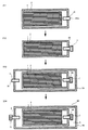
図5は、従来の電池の製造方法を説明する図である。図5に示したように、素電池が高圧流体によって加圧される形態の電池90を製造する場合、従来は、正極層と固体電解質層と負極層とを有する積層体1をラミネートフィルム2に入れ(S91)、ラミネートフィルム2内を減圧して気体排出路96の出口96xを封止材7で封止した後(S92)、ラミネートフィルム2を外装電池ケース94に入れ(S93)、外装電池ケース94内に流体5を注入した後に流体注入路8の入口8xを封止材9で封止していた(S94)。しかしながら、S91乃至S94を経る従来の製造工程では、減圧する工程であるS92と流体5を注入する工程であるS94とが別工程であるため、工程数が増大しやすかった。また、S92を行った後にS94を行う形態では、S92における減圧が不十分だと、S94で流体5を充填しても、ラミネートフィルム2内の残留気体が反発するため、密閉容器94に収容された積層体1を均一に加圧し難かった。
FIG. 5 is a diagram for explaining a conventional battery manufacturing method. As shown in FIG. 5, when manufacturing a
本発明者は、現状を改善すべく鋭意研究した結果、ラミネートフィルム2内から外部へと排出される気体が流通する気体排出路の出口を外装電池ケース4の外側に配置することにより、ラミネートフィルム2内の減圧と外装電池ケース4内への流体5の注入とを同時に行うことが可能になることを知見した。そして、ラミネートフィルム2内の減圧と流体5の注入とを同時に行う際には、まず、電池の加圧に必要な圧力以上になる量の流体をラミネートフィルム2外且つ外装電池ケース4内に注入してから、外装電池ケース4の外側に配置された気体排出路の出口を塞ぎ、外装電池ケース4内の流体の圧力を低下させた後に流体の注入口を塞ぐことにより、体積エネルギー密度や重量エネルギー密度を向上させつつ、ラミネートフィルム2に収容された積層体1を均一に加圧することが可能になることを知見した。本発明は、かかる知見に基づいてなされたものである。
As a result of diligent research to improve the current situation, the present inventor has arranged the outlet of the gas discharge passage through which the gas discharged from the inside of the laminated
以下、図面を参照しつつ、本発明の電池が、固体電解質層を用いたリチウムイオン二次電池(固体電池)である場合について説明する。なお、以下に示す形態は本発明の例示であり、本発明は以下に示す形態に限定されない。 Hereinafter, the case where the battery of the present invention is a lithium ion secondary battery (solid battery) using a solid electrolyte layer will be described with reference to the drawings. In addition, the form shown below is an illustration of this invention and this invention is not limited to the form shown below.
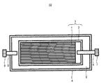
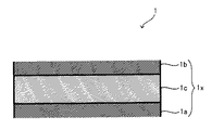
図1は、本発明の電池10を説明する断面図であり、図2は、電池10に備えられる積層体1を説明する断面図である。図2では、積層体1の一部を拡大して示している。図1に示したように、電池10は、積層体1及び該積層体を収容する素電池ケース2を備えた素電池3と、該素電池3を収容する外装電池ケース4と、を有し、素電池ケース2の外側且つ外装電池ケース4の内側には、流体5が充填されている。素電池ケース2には、素電池ケース2内の気体を外部へ放出する際に用いられる気体排出路6が接続されており、素電池ケース2の封止口である気体排出路6の一端は、外装電池ケース4の外側に位置している。外装電池ケース4の外側に位置している気体排出路6の一端(以下において、「気体排出路6の出口」という。)は、封止材7によって封止されている。また、外装電池ケース4には、素電池ケース2の外側且つ外装電池ケース4の内側に流体5を注入する際に用いられる流体注入路8が接続されており、外装電池ケース4の外側に位置している流体注入路8の一端(以下において、「流体注入路8の入口」という。)は、封止材9によって封止されている。
FIG. 1 is a cross-sectional view illustrating a
図2に示したように、積層体1は、正極層1aと、負極層1bと、正極層1a及び負極層1bに挟持された固体電解質層1cと、を有する電極体1xを備えている。正極層1aは不図示の正極集電体を介して不図示の正極端子に、負極層1bは不図示の負極集電体を介して不図示の負極端子に、それぞれ接続されており、正極端子及び負極端子は、その一端が外装電池ケース4の外側に位置している。積層体1は、1又は2以上の電極体1xを備えており、積層体1に2以上の電極体1x、1x、…が備えられている場合、隣接する電極体1x、1xは、電気的に直列又は並列に接続されている。
As shown in FIG. 2, the
このように構成される電池10は、例えば以下の工程を経て製造することができる。電池10を製造する際には、まず、正極層1a及び負極層1bの間に固体電解質層1cを配置する過程を経て積層体1を作製する。その後、正極端子及び負極端子の端部がラミネートフィルム2の外側に位置するようにしながら、積層体1を、気体排出路6が接続された素電池ケース2(以下において、「ラミネートフィルム2」ということがある。)で包み、ラミネートフィルム2の外縁を熱溶着等の公知の方法で接合することにより、素電池3を作製する。続いて、正極端子及び負極端子の端部、並びに、気体排出路6の出口が外装電池ケース4の外側に配置されるようにしながら、素電池3を、流体注入路8が接続された外装電池ケース4内に収容する。こうして、素電池3を外装電池ケース4内に収容したら、気体排出路6の出口を開けた状態で、ラミネートフィルム2の外側且つ外装電池ケース4の内側に流体5を充填する。気体排出路6の出口を開けた状態で流体5を注入することにより、ラミネートフィルム2を流体5で加圧することができ、ラミネートフィルム2内に残存している気体を、気体排出路6の出口から、外装電池ケース4の外側へと排出することができる。こうして、ラミネートフィルム2内に残存していた気体を外装電池ケース4の外側へと排出したら、気体排出路6の出口を封止材7で封止する。その後、流体5の圧力を、素電池2の加圧に適した圧力へと調整し、流体注入路8の入口を封止材9で封止する。例えば以上の工程を経ることにより、電池10を製造することができる。なお、電池10において、積層体1は、シート状の正極層1a、固体電解質層1c、及び、負極層1bを積層して形成したシート状形態であっても良く、シート状の正極層1a、固体電解質層1c、及び、負極層1bを積層した後に筒状に巻回して形成した筒状形態であっても良い。
The
気体排出路6の出口が外装電池ケース4の外側に位置している電池10によれば、ラミネートフィルム2の外側且つ外装電池ケース4の内側へ流体5を注入する際に、気体排出路6の出口を開けておくことにより、流体5を用いてラミネートフィルム2を容易に加圧することができる。流体5によって加圧されることにより、ラミネートフィルム2内に残存していた気体を外装電池ケース4の外側へと排出することができる。すなわち、ラミネートフィルム2内の減圧と流体5の注入とを同時に行うことができる。そして、流体注入路8の入口を封止する前に、気体排出路6の出口を封止することにより、外装電池ケース4の外側に存在している気体等がラミネートフィルム2の内側へ流入する事態を防止しながら、ラミネートフィルム2内の気体を低減すること(ラミネートフィルム2内を減圧すること)が可能になる。ラミネートフィルム2内を減圧することにより、ラミネートフィルム2の外側且つ外装電池ケース4の内側に充填された流体5によって、素電池3を均一に加圧することが可能になる。したがって、本発明によれば、素電池3を均一に加圧することが可能な、電池10を提供することができる。
According to the
電池10において、正極層1aに含有させる正極活物質としては、リチウムイオン二次電池の正極層に含有させることが可能な公知の正極活物質を適宜用いることができる。そのような正極活物質としては、コバルト酸リチウム(LiCoO2)等の層状化合物を例示することができる。また、正極層1aには、リチウムイオン二次電池の正極層に含有させることが可能な公知の固体電解質を適宜含有させることができる。そのような固体電解質としては、Li3PO4等の酸化物系固体電解質のほか、Li3PS4や、Li2S:P2S5=50:50〜100:0となるようにLi2S及びP2S5を混合して作製した硫化物系固体電解質(例えば、モル比で、Li2S:P2S5=75:25となるようにLi2S及びP2S5を混合して作製した硫化物固体電解質)等を例示することができる。このほか、正極層1aには、正極活物質と固体電解質とを結着させるバインダーや導電性を向上させる導電材が含有されていても良い。正極層1aに含有させることが可能なバインダーとしては、ブチレンゴム等を例示することができ、正極層1aに含有させることが可能な導電材としては、カーボンブラック等を例示することができる。また、正極層1aの作製時には、リチウムイオン二次電池の正極層作製時に用いるスラリーを調整する際に使用可能な公知の溶媒を適宜用いることができる。そのような溶媒としては、ヘプタン等を例示することができる。In the
また、負極層1bに含有させる負極活物質としては、リチウムイオン二次電池の負極層に含有させることが可能な公知の負極活物質を適宜用いることができる。そのような負極活物質としては、グラファイト等を例示することができる。また、負極層1bには固体電解質を含有させることができ、リチウムイオン二次電池の負極層に含有させることが可能な公知の固体電解質を適宜含有させることができる。そのような固体電解質としては、正極層1aに含有させることが可能な上記固体電解質等を例示することができる。このほか、負極層1bには、負極活物質と固体電解質とを結着させるバインダーや導電性を向上させる導電材が含有されていても良い。負極層1bに含有させることが可能なバインダーや導電材としては、正極層1aに含有させることが可能な上記バインダーや導電材等を例示することができる。また、負極層1bの作製時には、正極層1aの作製時に使用可能な上記溶媒等を適宜用いることができる。 Moreover, as a negative electrode active material contained in the negative electrode layer 1b, the well-known negative electrode active material which can be contained in the negative electrode layer of a lithium ion secondary battery can be used suitably. Examples of such a negative electrode active material include graphite. The negative electrode layer 1b can contain a solid electrolyte, and can appropriately contain a known solid electrolyte that can be contained in the negative electrode layer of the lithium ion secondary battery. Examples of such a solid electrolyte include the solid electrolyte that can be contained in the positive electrode layer 1a. In addition, the negative electrode layer 1b may contain a binder that binds the negative electrode active material and the solid electrolyte or a conductive material that improves conductivity. Examples of the binder and conductive material that can be contained in the negative electrode layer 1b include the binder and conductive material that can be contained in the positive electrode layer 1a. Moreover, the said solvent etc. which can be used at the time of preparation of the positive electrode layer 1a can be used suitably at the time of preparation of the negative electrode layer 1b.
また、固体電解質層1cに含有させる固体電解質としては、正極層1aに含有させることが可能な上記固体電解質等を例示することができる。また、固体電解質層1cの作製時には、正極層1aの作製時に使用可能な上記溶媒等を適宜用いることができる。
Examples of the solid electrolyte contained in the
また、正極集電体及び負極集電体、並びに、正極端子及び負極端子は、リチウムイオン二次電池の正極集電体及び負極集電体、並びに、正極端子及び負極端子として使用可能な公知の導電性材料によって構成することができる。そのような導電性材料としては、Cu、Ni、Al、V、Au、Pt、Mg、Fe、Ti、Co、Cr、Zn、Ge、Inからなる群から選択される一又は二以上の元素を含む金属材料を例示することができる。 Moreover, the positive electrode current collector and the negative electrode current collector, as well as the positive electrode terminal and the negative electrode terminal are known positive electrodes and negative electrode current collectors that can be used as the positive electrode terminal and the negative electrode terminal of the lithium ion secondary battery. It can be made of a conductive material. Examples of such a conductive material include one or more elements selected from the group consisting of Cu, Ni, Al, V, Au, Pt, Mg, Fe, Ti, Co, Cr, Zn, Ge, and In. Examples of the metal material to be included can be given.
また、素電池ケース2(ラミネートフィルム2)は、リチウムイオン二次電池の使用時の環境に耐えることができ、気体や液体を透過させない性質を有し、且つ、密封することができるフィルムを、特に限定されることなく用いることができる。そのようなフィルムの構成材料としては、ポリエチレン、ポリフッ化ビニルやポリ塩化ビニリデン等の樹脂フィルムのほか、これらの表面にアルミニウム等の金属を蒸着させた金属蒸着フィルム等を例示することができる。 In addition, the unit cell case 2 (laminate film 2) is a film that can withstand the environment during use of the lithium ion secondary battery, has a property of not allowing gas and liquid to permeate, and can be sealed. It can use without being specifically limited. Examples of the constituent material of such a film include resin films such as polyethylene, polyvinyl fluoride, and polyvinylidene chloride, and metal deposited films obtained by depositing a metal such as aluminum on these surfaces.
また、外装電池ケース4は、電池10の作動時の環境、及び、流体5の圧力に耐え得る材料によって構成されていれば、その構成材料は特に限定されない。外装電池ケース4は、例えば、アルミニウムやステンレス鋼等の金属製とすることができる。
The
また、流体5は、二酸化炭素等に代表される不燃性の気体のほか、ヘリウム、窒素、アルゴン等に代表される不活性の気体等を用いることができる。このほか、流体5としては、乾燥空気を用いることも可能である。ただし、電池の安全性を高めやすい形態にする等の観点からは、上記不燃性の気体や不活性の気体を用いることが好ましい。電池10において、素電池3を加圧する流体5の圧力は、例えば、1気圧以上200気圧以下程度とすることができる。
The
また、気体排出路6及び流体注入路8は、流体5の圧力に耐え得る材料によって構成されていれば、その構成材料は特に限定されない。気体排出路6及び流体注入路8は、例えば、編込まれた金属線を埋め込んで補強された樹脂によって形成された公知の管等を適宜用いることができる。
Moreover, if the
また、封止材7は、外装電池ケース4の外側に存在する気体等がラミネートフィルム2へと流入しないように、気体排出路6の出口を塞ぐことが可能な公知の物質を適宜用いることができる。そのような物質としては、アルミニウム箔等に代表される公知の金属箔等やエポキシ樹脂等の熱硬化性樹脂等を例示することができる。
Further, as the sealing material 7, a known substance capable of closing the outlet of the
また、封止材9は、外装電池ケース4の内側に充填された流体5が外装電池ケース4の外側へと漏洩しないように、流体注入路8の入口を塞ぐことが可能な公知の物質を適宜用いることができる。そのような物質としては、アルミニウム箔等に代表される公知の金属箔等やエポキシ樹脂等の熱硬化性樹脂等を例示することができる。
The sealing
電池10に関する上記説明では、流体5として気体を例示したが、本発明における流体5は気体に限定されない。流体5は公知の液体であっても良く、気体や液体と共に固体を用いることも可能である。
In the above description regarding the
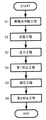
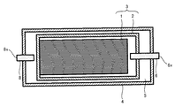
図3は、本発明の電池の製造方法を説明するフロー図であり、図4は、注入工程を説明する断面図である。以下、図1乃至図4を参照しつつ、本発明の電池の製造方法によって電池10を製造する場合について、説明する。
FIG. 3 is a flow diagram for explaining a method for producing a battery of the present invention, and FIG. 4 is a cross-sectional view for explaining an injection process. Hereinafter, the case where the
図3に示したように、本発明の電池の製造方法は、素電池作製工程(S1)と、収容工程(S2)と、注入工程(S3)と、第1封止工程(S4)と、減圧工程(S5)と、第2封止工程(S6)と、を有している。電池10は、これらの工程を経て、製造することができる。
As shown in FIG. 3, the battery manufacturing method of the present invention includes a unit cell manufacturing step (S1), a housing step (S2), an injection step (S3), a first sealing step (S4), It has a decompression step (S5) and a second sealing step (S6). The
素電池作製工程(以下において、「S1」という。)は、素電池3を作製する工程である。S1は、積層体1を作製する工程と、気体排出路6が接続されたラミネートフィルム2に積層体1を収容する工程と、に大別することができる。
The unit cell manufacturing step (hereinafter referred to as “S1”) is a step of manufacturing the
積層体1を作製するには、例えば、少なくとも正極活物質及び固体電解質を溶媒に分散して作製した正極用組成物を、正極集電体の表面に塗布する過程を経て、正極集電体の表面に正極層1aを形成する。また、負極活物質及び固体電解質を溶媒に分散して作製した負極用組成物を、負極集電体の表面に塗布する過程を経て、負極集電体の表面に負極層1bを形成する。そして、固体電解質を溶媒に分散して作製した電解質組成物を、例えば正極層1aの表面に塗布する過程を経て固体電解質層1cを形成した後、固体電解質層1cが正極層1a及び負極層1bで挟まれるように、正極層1aの表面に形成された固体電解質層1cの上に、負極集電体の表面に形成された負極層1bを配置する。その後、負極集電体、負極層1b、固体電解質層1c、正極層1a、及び、正極集電体の積層方向(厚さ方向)の両端側から圧縮力を付与することにより、積層体1を作製することができる。なお、積層体1が筒状形態である場合には、例えば、厚さ方向の両端側から圧縮力を付与した後に、筒状に巻回して筒状体とし、その後、筒状体の端面同士を接合する過程を経て、筒状形態の積層体1を作製することができる。
In order to produce the
こうして積層体1を作製したら、負極端子に接続される負極集電体の端部、及び、正極端子に接続される正極集電体の端部の全部を収容しないようにしながら、気体排出路6が接続されたラミネートフィルム2で積層体1を包む。ここで、気体排出路6は、公知の接着剤等を用いてラミネートフィルム2に接合することができる。積層体1をラミネートフィルム2で包んだら、例えば、積層体1の周りに位置しているラミネートフィルム2(ラミネートフィルム2の外縁)を加熱し熱溶着する等の過程を経て、積層体1と該積層体1を包むラミネートフィルム2とを有する、素電池3を作製することができる。
When the
収容工程(以下において、「S2」という。)は、素電池ケース2の封止口に相当する気体排出路6の出口6xが外装電池ケース4の外側に配置されるようにしながら、S1で作製した素電池3を外装電池ケース4内に収容する工程である。外装電池ケース4が、開口部を有し且つ流体注入路8が接続されている筐体と、該筐体の開口部を塞ぐ蓋とを有する形態である場合、S2は以下に示す工程とすることができる。まず、筐体の外側に端部が位置する正極端子と正極集電体とが接続され、且つ、筐体の外側に端部が位置する負極端子と負極集電体とが接続されるように、筐体の開口部から素電池3を筐体内へと収容する。その後、気体排出路6の出口6xが外装電池ケース4の外側に配置されるように、蓋に設けられている気体排出路6用の孔に気体排出路6を通し、筐体の開口部を蓋で塞ぐ。こうして筐体の開口部を蓋で塞いだら、筐体と蓋とを接合し、筐体に設けられている正極端子用の孔及び負極端子用の孔、並びに、蓋に設けられている気体排出路6用の孔を塞ぐ。例えば、このような形態のS2により、素電池3を外装電池ケース4内に収容することができる。
The housing step (hereinafter referred to as “S2”) is made in S1 while the
注入工程(以下において、「S3」ということがある。)は、上記S2の後に、気体排出路6の出口6xを開けた状態で、流体注入路8の入口8xから、ラミネートフィルム2の外側且つ外装電池ケース4の内側に、流体5を注入する工程である。S3実施時の、素電池3、外装電池ケース4、気体排出路6、及び、流体注入路8の断面を図4に示す。図4に示したように、S3は、気体排出路6の出口6xを開けた状態で行われる。S3をかかる形態とすることにより、流体5によって、ラミネートフィルム2の外側から内側へ向かって満遍なく力を付与することができ、ラミネートフィルム2の内側に存在する気体を、気体排出路6の出口6xから、外装電池ケース4の外側へと排出することができる。本発明の電池の製造方法では、S3で注入する流体5の圧力を調整することにより、気体排出路6の出口6xから排出される気体の量を調整することができる。より具体的には、S3で注入する流体5の圧力を高めることにより、気体排出路6の出口6xから排出される気体の量を増大すること、すなわち、ラミネートフィルム2内に残存する気体の量を低減することが可能になる。
In the injection step (hereinafter, sometimes referred to as “S3”), after S2, the
第1封止工程(以下において、「S4」ということがある。)は、上記S3の開始後に、気体排出路6の出口6xを封止材7で封止する工程である。気体排出路6の出口6xを封止する方法は特に限定されず、公知の方法を用いることができる。気体排出路6の出口6xを封止することにより、ラミネートフィルム2の内側に存在していた気体を外装電池ケース4の外側へ排出した状態(ラミネートフィルム2内を減圧した状態)を維持することが可能になる。
The first sealing step (hereinafter sometimes referred to as “S4”) is a step of sealing the
減圧工程(以下において、「S5」ということがある。)は、上記S4の後に、ラミネートフィルム2の外側且つ外装電池ケース4の内側に注入された流体5の圧力を低減する工程である。上述のように、上記S3で外装電池ケース4内に注入した流体5の圧力を高めることにより、ラミネートフィルム2内に存在する気体の量を低減することができる。本発明の電池の製造方法では、上記S3で注入した流体5の圧力をそのまま維持することも可能だが、流体5の圧力をそのまま維持するためには、ラミネートフィルム2及び外装電池ケース4が、当該圧力に耐え得る耐圧性能を有する必要がある。ラミネートフィルム2や外装電池ケース4の耐圧性能を高めるには、これらの厚さを厚くする等の対策を施す必要があり、こうした対策を施すと、電池の体積エネルギー密度や重量エネルギー密度が低下しやすい。体積エネルギー密度や重量エネルギー密度を高めた電池とするには、ラミネートフィルム2や外装電池ケース4の厚さを薄くすることが有効であり、厚さが薄いラミネートフィルム2や外装電池ケース4であっても、長期間に亘って素電池3を均一に加圧可能な形態とするためには、上記S4の後に、上記S3で注入した流体5の圧力を低減することが有効である。かかる観点から、図3に示した本発明の電池の製造方法では、上記S4の後に、S5を行う。S5は、例えば、ラミネートフィルム2の外側且つ外装電池ケース4の内側への、流体5の供給を停止した後、所定の時間に亘って、流体注入路8の入口8xを開けた状態とし、ラミネートフィルム2の外側且つ外装電池ケース4の内側に注入された流体5の一部を外装電池ケース4の外側へと排出することにより、流体5の圧力を低減する工程、とすることができる。
The depressurization step (hereinafter sometimes referred to as “S5”) is a step of reducing the pressure of the
第2封止工程(以下において、「S6」ということがある。)は、上記S5の後に、流体注入路8の入口8xを封止材9で封止する工程である。流体注入路8の入口8xを封止する方法は特に限定されず、公知の方法を用いることができる。流体注入路8の入口8xを封止することにより、流体5によって素電池3を均一に加圧する状態を維持することが可能になる。
The second sealing step (hereinafter sometimes referred to as “S6”) is a step of sealing the inlet 8x of the
このように、S1乃至S6を経る本発明の電池の製造方法によれば、素電池3を均一に加圧することが可能な、電池10を製造することができる。したがって、本発明によれば、素電池を均一に加圧し得る電池を製造することが可能な、電池の製造方法を提供することができる。
Thus, according to the battery manufacturing method of the present invention through S1 to S6, the
本発明の電池の製造方法に関する上記説明では、S3よりも後(より具体的には、S4の後)に減圧工程を有する形態を例示したが、本発明の電池の製造方法は当該形態に限定されない。ただし、体積エネルギー密度や重量エネルギー密度を向上させつつ、素電池を均一に加圧可能な形態とする等の観点からは、注入工程の後(例えば、第1封止工程の後)に減圧工程を有する形態とすることが好ましい。 In the above description regarding the method for manufacturing a battery of the present invention, a mode having a pressure reducing step after S3 (more specifically, after S4) has been exemplified, but the method for manufacturing a battery of the present invention is limited to this mode. Not. However, from the standpoint of improving the volume energy density and the weight energy density and making the unit cell into a form that can be uniformly pressurized, the pressure reducing process is performed after the injection process (for example, after the first sealing process). It is preferable to have a form having
また、本発明の電池の製造方法に関する上記説明では、気体排出路6の出口6xを封止材7で封止する第1封止工程の後に、流体注入路8の入口8xを封止材9で封止する第2封止工程を有する形態を例示したが、本発明の電池の製造方法は当該形態に限定されない。ただし、外装電池ケースの外側に存在する気体等が素電池ケース内へと流入する事態を抑制して、素電池ケース内に残存する気体の量を低減しやすい形態にする等の観点からは、注入工程の開始後に素電池ケースの封止口を封止する第1封止工程と、該第1封止工程後に、組電池ケースを封止する第2封止工程と、を有する形態とすることが好ましい。
In the above description of the battery manufacturing method of the present invention, after the first sealing step of sealing the
本発明に関する上記説明では、リチウムイオン二次電池及びその製造方法に本発明が適用される場合を例示したが、本発明は当該形態に限定されない。本発明の電池は、正極層と負極層との間を、リチウムイオン以外のイオンが移動する形態とすることも可能であり、本発明の電池の製造方法は、リチウムイオン以外のイオンが移動する電池を製造する方法とすることも可能である。そのようなイオンとしては、ナトリウムイオンやカリウムイオン、マグネシウムイオン、カルシウムイオン等を例示することができる。リチウムイオン以外のイオンが移動する形態とする場合、正極活物質、固体電解質、及び、負極活物質は、移動するイオンに応じて適宜選択すれば良い。 Although the case where this invention is applied to a lithium ion secondary battery and its manufacturing method was illustrated in the said description regarding this invention, this invention is not limited to the said form. The battery of the present invention may be configured such that ions other than lithium ions move between the positive electrode layer and the negative electrode layer, and the method for manufacturing a battery of the present invention moves ions other than lithium ions. It is also possible to use a method for manufacturing a battery. Examples of such ions include sodium ions, potassium ions, magnesium ions, calcium ions, and the like. In the case where ions other than lithium ions move, the positive electrode active material, the solid electrolyte, and the negative electrode active material may be appropriately selected according to the moving ions.
また、本発明に関する上記説明では、固体電解質層を有する固体電池及びその製造方法に本発明が適用される場合を例示したが、本発明は当該形態に限定されない。本発明の電池は、電解液を用いた電解質層を有する電池であっても良く、本発明の電池の製造方法は、電解液を用いた電解質層を有する電池を製造する方法とすることも可能である。ただし、電解液を用いた電解質層を有する電池よりも、固体電池の方が、性能を高めるために、素電池を均一に加圧する必要性が高い。それゆえ、性能を高めた電池及びその製造方法を提供しやすい形態にする等の観点からは、固体電池及びその製造方法に本発明を適用することが好ましい。 Moreover, in the said description regarding this invention, although the case where this invention was applied to the solid battery which has a solid electrolyte layer, and its manufacturing method was illustrated, this invention is not limited to the said form. The battery of the present invention may be a battery having an electrolyte layer using an electrolytic solution, and the battery manufacturing method of the present invention may be a method of manufacturing a battery having an electrolyte layer using an electrolytic solution. It is. However, in order to improve the performance of the solid battery, it is more necessary to pressurize the unit cell uniformly than the battery having the electrolyte layer using the electrolytic solution. Therefore, it is preferable to apply the present invention to a solid state battery and a manufacturing method thereof from the viewpoint of easily providing a battery with improved performance and a manufacturing method thereof.
また、本発明に関する上記説明では、充放電可能な二次電池及びその製造方法に本発明が適用される場合を例示したが、本発明は当該形態に限定されない。本発明の電池は、いわゆる一次電池であっても良く、本発明の電池の製造方法は、一次電池を製造する方法とすることも可能である。 Moreover, in the said description regarding this invention, although the case where this invention was applied to the secondary battery which can be charged / discharged, and its manufacturing method was illustrated, this invention is not limited to the said form. The battery of the present invention may be a so-called primary battery, and the battery manufacturing method of the present invention may be a method of manufacturing a primary battery.
1…積層体
1a…正極層
1b…負極層
1c…固体電解質層(電解質層)
1x…電極体
2…ラミネートフィルム(素電池ケース)
3…素電池
4、94…外装電池ケース
5…流体
6、96…気体排出路
6x、96x…出口(素電池ケースの封止口)
7、9…封止材
8…流体注入路
8x…入口
10、90…電池DESCRIPTION OF
1x ...
3 ...
7, 9 ...
上記課題を解決するために、本発明は以下の手段をとる。すなわち、
本発明の第1の態様は、正極層、負極層、及び、正極層と負極層との間に配設された電解質層を有する積層体、並びに、該積層体を収容する素電池ケースを備えた素電池と、該素電池を収容する外装電池ケースと、を具備し、素電池ケースの外側且つ外装電池ケースの内側に、素電池を加圧可能な流体が充填され、素電池ケースに気体排出路が接続され、該気体排出路の封止口が、外装電池ケースの外側にあることを特徴とする、電池である。
In order to solve the above problems, the present invention takes the following means. That is,
A first aspect of the present invention includes a laminate having a positive electrode layer, a negative electrode layer, and an electrolyte layer disposed between the positive electrode layer and the negative electrode layer, and a unit cell case containing the laminate. A unit cell and an outer battery case that accommodates the unit cell, and a fluid capable of pressurizing the unit cell is filled inside and outside the unit cell case, and the unit cell case is filled with gas. The battery is characterized in that a discharge path is connected and a sealing port of the gas discharge path is outside the outer battery case.
本発明の第2の態様は、正極層、負極層、及び、正極層と負極層との間に配設された電解質層を有する積層体、並びに、該積層体を収容する素電池ケースを備えた素電池と、該素電池を収容する外装電池ケースと、を具備する電池を製造する方法であって、素電池を作製する素電池作製工程と、該素電池作製工程後に、素電池ケースに接続されている気体排出路の封止口が外装電池ケースの外側に配置されるようにしながら、素電池を外装電池ケース内に収容する収容工程と、該収容工程後に、上記気体排出路の封止口を開けた状態で、素電池ケースの外側且つ外装電池ケースの内側に、素電池を加圧すべき流体を注入する注入工程と、を有することを特徴とする、電池の製造方法である。
A second aspect of the present invention includes a laminate having a positive electrode layer, a negative electrode layer, and an electrolyte layer disposed between the positive electrode layer and the negative electrode layer, and a unit cell case containing the laminate. A battery comprising: a unit cell; and an outer battery case that accommodates the unit cell, wherein the unit cell manufacturing step for manufacturing the unit cell, and after the unit cell manufacturing step , A housing step of housing the unit cell in the outer battery case while the sealing port of the connected gas exhaust passage is arranged outside the outer battery case, and after the housing step, sealing the gas exhaust passage An injecting step of injecting a fluid to pressurize the unit cell into the outside of the unit cell case and the inside of the outer cell case with the stop open is provided.
本発明の第1の態様にかかる電池では、素電池ケースに接続されている気体排出路の封止口が外装電池ケースの外側にある。それゆえ、素電池ケースの外側且つ外装電池ケースの内側に、素電池を加圧すべき流体を封入する際に、素電池ケース内に残存していた気体を素電池ケース外且つ外装電池ケース外へと排出することができ、これによって、素電池ケース内に残存する気体を低減することができる。素電池ケース内に残存する気体を低減することにより、素電池ケースの外側に充填される流体を用いて素電池を均一に加圧することが可能になる。したがって、本発明の第1の態様によれば、素電池を均一に加圧することが可能な、電池を提供することができる。
In the battery according to the first aspect of the present invention, the sealing port of the gas discharge path connected to the unit cell case is outside the outer battery case. Therefore, when the fluid to pressurize the unit cell is sealed outside the unit cell case and inside the outer cell case, the gas remaining in the unit cell case is moved out of the unit cell case and outside the unit cell case. As a result, the gas remaining in the unit cell case can be reduced. By reducing the gas remaining in the unit cell case, it is possible to uniformly pressurize the unit cell using the fluid filled outside the unit cell case. Therefore, according to the 1st aspect of this invention, the battery which can pressurize a unit cell uniformly can be provided.
本発明の第2の態様は、外装電池ケースの外側に配置された素電池ケースの封止口である気体排出路の封止口を開けた状態で、素電池を加圧すべき流体を注入する注入工程を有している。注入工程を、気体排出路の封止口を開けた状態で行うことにより、注入された流体を用いて素電池ケースを加圧しながら、流体によって加圧された素電池ケース内に残存する気体を素電池ケースの外へと排出することができるので、素電池ケース内に残存する気体を低減することができる。素電池ケース内に存在する気体を低減することにより、素電池ケースの外側に充填される流体を用いて素電池を均一に加圧することが可能になるので、本発明の第2の態様によれば、素電池を均一に加圧し得る電池を製造することが可能な、電池の製造方法を提供することができる。 According to a second aspect of the present invention, a fluid to be pressurized is injected in a state where a sealing port of a gas discharge path which is a sealing port of a unit cell case arranged outside the outer battery case is opened. It has an injection process. By performing the injection process with the sealing port of the gas discharge passage opened, the gas remaining in the unit cell case pressurized by the fluid is compressed while the unit cell case is pressurized using the injected fluid. Since it can discharge | emit out of a unit cell case, the gas which remains in a unit cell case can be reduced. By reducing the gas present in the unit cell case, it becomes possible to pressurize the unit cell uniformly using the fluid filled outside the unit cell case, so according to the second aspect of the present invention. Thus, it is possible to provide a battery manufacturing method capable of manufacturing a battery capable of uniformly pressing the unit cell.
Claims (3)
前記素電池ケースの外側且つ前記外装電池ケースの内側に、前記素電池を加圧可能な流体が充填され、
前記素電池ケースの封止口が、前記外装電池ケースの外側にあることを特徴とする、電池。A unit cell comprising a positive electrode layer, a negative electrode layer, a laminate having an electrolyte layer disposed between the positive electrode layer and the negative electrode layer, and a unit cell case containing the laminate, and the element An exterior battery case that houses the battery,
The outside of the unit cell case and the inside of the exterior battery case are filled with a fluid capable of pressurizing the unit cell,
The battery according to claim 1, wherein the sealing opening of the unit cell case is outside the outer battery case.
前記素電池を作製する素電池作製工程と、
前記素電池作製工程後に、前記素電池ケースの封止口が前記外装電池ケースの外側に配置されるようにしながら、前記素電池を前記外装電池ケース内に収容する収容工程と、
前記収容工程後に、前記素電池ケースの前記封止口を開けた状態で、前記素電池ケースの外側且つ前記外装電池ケースの内側に、前記素電池を加圧すべき流体を注入する注入工程と、
を有することを特徴とする、電池の製造方法。A unit cell comprising a positive electrode layer, a negative electrode layer, a laminate having an electrolyte layer disposed between the positive electrode layer and the negative electrode layer, and a unit cell case containing the laminate, and the element An outer battery case containing the battery, and a method of manufacturing a battery comprising:
A unit cell manufacturing process for manufacturing the unit cell;
An accommodating step of accommodating the unit cell in the exterior battery case while the sealing opening of the unit cell case is disposed outside the exterior battery case after the unit cell manufacturing step;
An injection step of injecting a fluid to pressurize the unit cell into the outside of the unit cell case and the inside of the exterior battery case in a state where the sealing port of the unit cell case is opened after the accommodating step;
A method for producing a battery, comprising:
前記注入工程後に、前記素電池を加圧すべき前記流体の圧力を、前記第1の圧力よりも低減する減圧工程を有することを特徴とする、請求項2に記載の電池の製造方法。In the injection step, the fluid is injected until the pressure of the fluid becomes a first pressure,
3. The battery manufacturing method according to claim 2, further comprising a pressure reducing step of reducing a pressure of the fluid to pressurize the unit cell after the injecting step to be lower than the first pressure. 4.
Applications Claiming Priority (1)
| Application Number | Priority Date | Filing Date | Title |
|---|---|---|---|
| PCT/JP2011/061949 WO2012160661A1 (en) | 2011-05-25 | 2011-05-25 | Battery and method for manufacturing same |
Publications (2)
| Publication Number | Publication Date |
|---|---|
| JP5382134B2 JP5382134B2 (en) | 2014-01-08 |
| JPWO2012160661A1 true JPWO2012160661A1 (en) | 2014-07-31 |
Family
ID=47216764
Family Applications (1)
| Application Number | Title | Priority Date | Filing Date |
|---|---|---|---|
| JP2011542610A Expired - Fee Related JP5382134B2 (en) | 2011-05-25 | 2011-05-25 | Battery and manufacturing method thereof |
Country Status (4)
| Country | Link |
|---|---|
| US (1) | US20140162115A1 (en) |
| JP (1) | JP5382134B2 (en) |
| CN (1) | CN102906898B (en) |
| WO (1) | WO2012160661A1 (en) |
Families Citing this family (9)
| Publication number | Priority date | Publication date | Assignee | Title |
|---|---|---|---|---|
| CA3109523A1 (en) * | 2018-08-30 | 2020-03-05 | Hydro-Quebec | Rechargeable battery with ionic liquid electrolyte and electrode pressure |
| US10403925B1 (en) * | 2018-12-11 | 2019-09-03 | Chongqing Jinkang New Energy Automobile Co., Ltd. | Hydraulic isostatic press processes for solid-state batteries |
| CN110828745B (en) * | 2020-01-13 | 2020-07-10 | 比亚迪股份有限公司 | A battery, battery module, battery pack and electric vehicle |
| CN212587593U (en) * | 2020-01-13 | 2021-02-23 | 比亚迪股份有限公司 | A battery, battery module, battery pack and electric vehicle |
| JP7266564B2 (en) * | 2020-10-20 | 2023-04-28 | プライムプラネットエナジー&ソリューションズ株式会社 | BATTERY CASE FOR NON-AQUEOUS ELECTROLYTE SECONDARY BATTERY AND USE THEREOF |
| EP4213259A1 (en) * | 2022-01-12 | 2023-07-19 | Hana Technology Co., Ltd. | System and method for pressurizing all-solid-state secondary battery at high temperature |
| KR102622321B1 (en) * | 2022-01-12 | 2024-01-08 | (주)하나기술 | Pressurizing system of all solid state secondary battery with high temperature and method thereof |
| KR20230125553A (en) * | 2022-02-21 | 2023-08-29 | 주식회사 엘지에너지솔루션 | Battery cell pressing device and battery cell charging and discharging device including the same |
| JP2025067065A (en) * | 2023-10-12 | 2025-04-24 | トヨタ自動車株式会社 | Laminate battery |
Family Cites Families (16)
| Publication number | Priority date | Publication date | Assignee | Title |
|---|---|---|---|---|
| JPH07220753A (en) * | 1994-01-31 | 1995-08-18 | Sony Corp | Battery assembly |
| JPH10214638A (en) * | 1997-01-30 | 1998-08-11 | Hitachi Ltd | Lithium secondary battery |
| DE19837909C2 (en) * | 1998-08-20 | 2001-05-17 | Implex Hear Tech Ag | Protection device for a multi-rechargeable electrochemical battery |
| JP3791841B2 (en) * | 2002-08-29 | 2006-06-28 | 三菱化学株式会社 | Leakage inspection method for shape-variable packaging body, battery inspection method using the same, and battery manufacturing method |
| KR100560158B1 (en) * | 2003-09-29 | 2006-03-16 | 주식회사 코캄 | High safety lithium secondary battery and its manufacturing method |
| JP5266634B2 (en) * | 2006-12-08 | 2013-08-21 | 日産自動車株式会社 | Power supply apparatus and control method thereof |
| WO2008099602A1 (en) * | 2007-02-16 | 2008-08-21 | Panasonic Corporation | Electric storage unit |
| CN101222071A (en) * | 2007-03-22 | 2008-07-16 | 胡远明 | Sodium sulfur accumulator |
| US7967025B2 (en) * | 2007-08-03 | 2011-06-28 | Scg (Thailand) Co., Ltd. | Overfill protection device (OPD) |
| JP2010108788A (en) * | 2008-10-30 | 2010-05-13 | Sanyo Electric Co Ltd | Battery system |
| JP5509684B2 (en) * | 2009-06-03 | 2014-06-04 | ソニー株式会社 | Battery pack |
| CN101710629B (en) * | 2009-11-03 | 2012-05-30 | 赛恩斯能源科技有限公司 | Battery Pack Charging Method |
| JP5649811B2 (en) * | 2009-11-09 | 2015-01-07 | 三洋電機株式会社 | VEHICLE POWER SUPPLY DEVICE, VEHICLE HAVING THE SAME, AND MANUFACTURING METHOD FOR VEHICLE POWER SOURCE |
| JP5257471B2 (en) * | 2010-12-28 | 2013-08-07 | トヨタ自動車株式会社 | battery |
| JP2012195143A (en) * | 2011-03-16 | 2012-10-11 | Toyota Motor Corp | Battery system |
| JP2012221580A (en) * | 2011-04-04 | 2012-11-12 | Toyota Motor Corp | Solid-state battery |
-
2011
- 2011-05-25 CN CN201180003881.7A patent/CN102906898B/en not_active Expired - Fee Related
- 2011-05-25 US US13/395,507 patent/US20140162115A1/en not_active Abandoned
- 2011-05-25 WO PCT/JP2011/061949 patent/WO2012160661A1/en not_active Ceased
- 2011-05-25 JP JP2011542610A patent/JP5382134B2/en not_active Expired - Fee Related
Also Published As
| Publication number | Publication date |
|---|---|
| CN102906898B (en) | 2015-09-09 |
| JP5382134B2 (en) | 2014-01-08 |
| CN102906898A (en) | 2013-01-30 |
| US20140162115A1 (en) | 2014-06-12 |
| WO2012160661A1 (en) | 2012-11-29 |
Similar Documents
| Publication | Publication Date | Title |
|---|---|---|
| JP5382134B2 (en) | Battery and manufacturing method thereof | |
| US11942654B2 (en) | Dual electrolyte electrochemical cells, systems, and methods of manufacturing the same | |
| CN108428815B (en) | Method for manufacturing laminated all-solid-state battery | |
| US9818996B2 (en) | Solid battery and method for manufacturing solid battery | |
| CN104934649B (en) | Solid state battery and its manufacture method and Battery pack and its manufacture method | |
| TWI496335B (en) | Battery cell of stair-like structure | |
| JP5610057B2 (en) | Solid battery | |
| JP5581916B2 (en) | Bipolar secondary battery manufacturing apparatus and manufacturing method, and gas discharge apparatus | |
| CN102842732A (en) | Secondary battery and method for producing same | |
| JP4601917B2 (en) | Secondary battery and manufacturing method thereof | |
| JP2013093216A (en) | Battery | |
| WO2013021432A1 (en) | Solid-state battery and method for producing same | |
| CN104538677A (en) | Flexibly-packaged lithium ion battery and preparation method thereof | |
| JP2003217671A (en) | Manufacturing method of sealed battery and method of evaluating sealing performance of sealed battery | |
| JP2013065451A (en) | Battery | |
| JP2012248294A (en) | Battery | |
| WO2013008816A1 (en) | Battery | |
| JP5545237B2 (en) | Solid battery | |
| JP7503040B2 (en) | Secondary battery manufacturing method | |
| JP7692499B2 (en) | Secondary battery manufacturing method | |
| JP7753390B2 (en) | Secondary battery manufacturing method | |
| WO2019087668A1 (en) | Separator slurry, secondary battery electrode and method for manufacturing same, and secondary battery | |
| JP2013069529A (en) | Method for manufacturing battery | |
| JP2013084358A (en) | Method of manufacturing battery | |
| KR20260038667A (en) | Method for precharging of secondary battery and manufacturing method thereof adopting the precharging |
Legal Events
| Date | Code | Title | Description |
|---|---|---|---|
| TRDD | Decision of grant or rejection written | ||
| A01 | Written decision to grant a patent or to grant a registration (utility model) |
Free format text: JAPANESE INTERMEDIATE CODE: A01 Effective date: 20130903 |
|
| A61 | First payment of annual fees (during grant procedure) |
Free format text: JAPANESE INTERMEDIATE CODE: A61 Effective date: 20130916 |
|
| LAPS | Cancellation because of no payment of annual fees |