JPWO2007125756A1 - Micro structure inspection apparatus and micro structure inspection method - Google Patents
Micro structure inspection apparatus and micro structure inspection method Download PDFInfo
- Publication number
- JPWO2007125756A1 JPWO2007125756A1 JP2008513136A JP2008513136A JPWO2007125756A1 JP WO2007125756 A1 JPWO2007125756 A1 JP WO2007125756A1 JP 2008513136 A JP2008513136 A JP 2008513136A JP 2008513136 A JP2008513136 A JP 2008513136A JP WO2007125756 A1 JPWO2007125756 A1 JP WO2007125756A1
- Authority
- JP
- Japan
- Prior art keywords
- microstructure
- probe
- nozzles
- inspection apparatus
- flow rate
- Prior art date
- Legal status (The legal status is an assumption and is not a legal conclusion. Google has not performed a legal analysis and makes no representation as to the accuracy of the status listed.)
- Pending
Links
Images


Classifications
-
- H—ELECTRICITY
- H01—ELECTRIC ELEMENTS
- H01L—SEMICONDUCTOR DEVICES NOT COVERED BY CLASS H10
- H01L22/00—Testing or measuring during manufacture or treatment; Reliability measurements, i.e. testing of parts without further processing to modify the parts as such; Structural arrangements therefor
-
- G—PHYSICS
- G01—MEASURING; TESTING
- G01P—MEASURING LINEAR OR ANGULAR SPEED, ACCELERATION, DECELERATION, OR SHOCK; INDICATING PRESENCE, ABSENCE, OR DIRECTION, OF MOVEMENT
- G01P21/00—Testing or calibrating of apparatus or devices covered by the preceding groups
-
- B—PERFORMING OPERATIONS; TRANSPORTING
- B81—MICROSTRUCTURAL TECHNOLOGY
- B81C—PROCESSES OR APPARATUS SPECIALLY ADAPTED FOR THE MANUFACTURE OR TREATMENT OF MICROSTRUCTURAL DEVICES OR SYSTEMS
- B81C99/00—Subject matter not provided for in other groups of this subclass
- B81C99/0035—Testing
- B81C99/005—Test apparatus
-
- G—PHYSICS
- G01—MEASURING; TESTING
- G01P—MEASURING LINEAR OR ANGULAR SPEED, ACCELERATION, DECELERATION, OR SHOCK; INDICATING PRESENCE, ABSENCE, OR DIRECTION, OF MOVEMENT
- G01P15/00—Measuring acceleration; Measuring deceleration; Measuring shock, i.e. sudden change of acceleration
- G01P15/02—Measuring acceleration; Measuring deceleration; Measuring shock, i.e. sudden change of acceleration by making use of inertia forces using solid seismic masses
- G01P15/08—Measuring acceleration; Measuring deceleration; Measuring shock, i.e. sudden change of acceleration by making use of inertia forces using solid seismic masses with conversion into electric or magnetic values
- G01P15/12—Measuring acceleration; Measuring deceleration; Measuring shock, i.e. sudden change of acceleration by making use of inertia forces using solid seismic masses with conversion into electric or magnetic values by alteration of electrical resistance
- G01P15/123—Measuring acceleration; Measuring deceleration; Measuring shock, i.e. sudden change of acceleration by making use of inertia forces using solid seismic masses with conversion into electric or magnetic values by alteration of electrical resistance by piezo-resistive elements, e.g. semiconductor strain gauges
-
- G—PHYSICS
- G01—MEASURING; TESTING
- G01P—MEASURING LINEAR OR ANGULAR SPEED, ACCELERATION, DECELERATION, OR SHOCK; INDICATING PRESENCE, ABSENCE, OR DIRECTION, OF MOVEMENT
- G01P15/00—Measuring acceleration; Measuring deceleration; Measuring shock, i.e. sudden change of acceleration
- G01P15/18—Measuring acceleration; Measuring deceleration; Measuring shock, i.e. sudden change of acceleration in two or more dimensions
-
- G—PHYSICS
- G01—MEASURING; TESTING
- G01P—MEASURING LINEAR OR ANGULAR SPEED, ACCELERATION, DECELERATION, OR SHOCK; INDICATING PRESENCE, ABSENCE, OR DIRECTION, OF MOVEMENT
- G01P15/00—Measuring acceleration; Measuring deceleration; Measuring shock, i.e. sudden change of acceleration
- G01P15/02—Measuring acceleration; Measuring deceleration; Measuring shock, i.e. sudden change of acceleration by making use of inertia forces using solid seismic masses
- G01P15/08—Measuring acceleration; Measuring deceleration; Measuring shock, i.e. sudden change of acceleration by making use of inertia forces using solid seismic masses with conversion into electric or magnetic values
- G01P2015/0805—Measuring acceleration; Measuring deceleration; Measuring shock, i.e. sudden change of acceleration by making use of inertia forces using solid seismic masses with conversion into electric or magnetic values being provided with a particular type of spring-mass-system for defining the displacement of a seismic mass due to an external acceleration
- G01P2015/0822—Measuring acceleration; Measuring deceleration; Measuring shock, i.e. sudden change of acceleration by making use of inertia forces using solid seismic masses with conversion into electric or magnetic values being provided with a particular type of spring-mass-system for defining the displacement of a seismic mass due to an external acceleration for defining out-of-plane movement of the mass
- G01P2015/084—Measuring acceleration; Measuring deceleration; Measuring shock, i.e. sudden change of acceleration by making use of inertia forces using solid seismic masses with conversion into electric or magnetic values being provided with a particular type of spring-mass-system for defining the displacement of a seismic mass due to an external acceleration for defining out-of-plane movement of the mass the mass being suspended at more than one of its sides, e.g. membrane-type suspension, so as to permit multi-axis movement of the mass
- G01P2015/0842—Measuring acceleration; Measuring deceleration; Measuring shock, i.e. sudden change of acceleration by making use of inertia forces using solid seismic masses with conversion into electric or magnetic values being provided with a particular type of spring-mass-system for defining the displacement of a seismic mass due to an external acceleration for defining out-of-plane movement of the mass the mass being suspended at more than one of its sides, e.g. membrane-type suspension, so as to permit multi-axis movement of the mass the mass being of clover leaf shape
-
- G—PHYSICS
- G01—MEASURING; TESTING
- G01R—MEASURING ELECTRIC VARIABLES; MEASURING MAGNETIC VARIABLES
- G01R31/00—Arrangements for testing electric properties; Arrangements for locating electric faults; Arrangements for electrical testing characterised by what is being tested not provided for elsewhere
- G01R31/28—Testing of electronic circuits, e.g. by signal tracer
- G01R31/282—Testing of electronic circuits specially adapted for particular applications not provided for elsewhere
- G01R31/2829—Testing of circuits in sensor or actuator systems
Abstract
多方向の自由度を有する微小構造体について、可動部に直に接触することなく、各自由度方向の特性の動的試験を行うことができる検査装置を提供する。基板(8)上に形成された可動部(16a)を有する、少なくとも1つの微小構造体(16)の特性を評価する微小構造体の検査装置であって、微小構造体(16)の電気信号を取り出すために、微小構造体(16)に形成されたパッド(8a)に電気的に接続するプローブ(4a)と、微小構造体(16)の可動部(16a)の近傍に配置され、気体を噴出又は吸入する複数のノズル(10)と、前記複数のノズル(10)から噴出又は吸入する気体の流量を制御するノズル流量制御部(3)と、ノズル(10)から噴出又は吸入する気体によって印加された可動部(16a)の変位を、プローブ(4a)を介して得られる電気信号によって検出し、検出結果に基づいて微小構造体(16)の特性を評価する評価手段と、を備える。Provided is an inspection apparatus capable of performing a dynamic test of characteristics in each direction of freedom of a microstructure having degrees of freedom in multiple directions without directly contacting a movable part. A microstructure inspection apparatus for evaluating the characteristics of at least one microstructure (16) having a movable portion (16a) formed on a substrate (8), the electrical signal of the microstructure (16) The probe (4a) electrically connected to the pad (8a) formed on the microstructure (16) and the movable portion (16a) of the microstructure (16) are disposed in the vicinity of the gas. A plurality of nozzles (10) for jetting or sucking gas, a nozzle flow rate control unit (3) for controlling the flow rate of gas jetted or sucked from the plurality of nozzles (10), and a gas jetted or sucked from the nozzle (10) And an evaluation means for detecting the displacement of the movable part (16a) applied by means of an electrical signal obtained via the probe (4a) and evaluating the characteristics of the microstructure (16) based on the detection result. .
Description
本発明は、微小構造体たとえばMEMS(Micro Electro Mechanical Systems)を検査する検査装置、及び検査方法に関する。 The present invention relates to an inspection apparatus and an inspection method for inspecting a microstructure such as MEMS (Micro Electro Mechanical Systems).
近年、特に半導体微細加工技術等を用いて、機械・電子・光・化学等の多用な機能を集積化したデバイスであるMEMSが注目されている。これまでに実用化されたMEMS技術としては、たとえば自動車又は医療用の各種センサがあり、マイクロセンサである加速度センサや圧力センサ、エアーフローセンサ等にMEMSデバイスが搭載されてきている。また、インクジェットプリンタヘッドにこのMEMS技術を採用することにより、インクを噴出するノズル数の増加と正確なインクの噴出が可能となり、画質の向上と印刷スピードの高速化を図ることが可能となっている。さらには、反射型のプロジェクタにおいて用いられているマイクロミラーアレイ等も一般的なMEMSデバイスとして知られている。 In recent years, MEMS, which is a device in which various functions such as mechanical, electronic, optical, chemical, etc., are integrated, particularly using semiconductor microfabrication technology, has attracted attention. Examples of MEMS technology that has been put to practical use so far include various sensors for automobiles and medical use, and MEMS devices have been mounted on acceleration sensors, pressure sensors, air flow sensors, and the like, which are microsensors. In addition, by adopting this MEMS technology in an ink jet printer head, it is possible to increase the number of nozzles that eject ink and to eject ink accurately, thereby improving image quality and increasing printing speed. Yes. Furthermore, a micromirror array used in a reflective projector is also known as a general MEMS device.
また、今後MEMS技術を利用したさまざまなセンサやアクチュエータが開発されることにより光通信・モバイル機器への応用、計算機の周辺機器への応用、さらにはバイオ分析や携帯用電源への応用へと展開することが期待されている。 In the future, various sensors and actuators using MEMS technology will be developed, which will be applied to optical communication and mobile devices, computer peripherals, bioanalysis and portable power supplies. Is expected to be.
一方で、MEMSデバイスの発展に伴い、微細な構造等であるがゆえにそれを適正に検査する方式も重要となってくる。従来、MEMSデバイスをパッケージした後にデバイスをパッケージごと回転させたり、あるいは振動させたりしてデバイスの特性の評価を実行してきたが、微細加工後のウエハ状態等の初期段階において適正な検査を実行して不良を検出することにより、製品の歩留りを向上させ、製造コストをより低減することが望ましい。 On the other hand, with the development of MEMS devices, a method for appropriately inspecting the fine structure is also important because of the fine structure. Conventionally, device characteristics are evaluated by rotating or vibrating the device after packaging the MEMS device. However, proper inspection is performed at the initial stage of the wafer state after microfabrication. Therefore, it is desirable to improve the product yield and reduce the manufacturing cost by detecting defects.
特許文献1においては、一例としてウエハ上に形成された加速度センサに対して、空気を吹き付けることにより変化する加速度センサの抵抗値を検出して加速度センサの特性を判別する検査方式が提案されている。
微小な可動部を有するMEMSデバイスはその特性を検査する際には、外部から物理的な刺激を与える必要がある。一般に、加速度センサ等の微小な可動部を有する構造体は、微小な動きに対してもその応答特性が変化するデバイスである。したがって、その特性を評価するためには、精度の高い検査をする必要がある。また、デバイスの可動部に非接触で検査することが望ましい。デバイスの可動部に非接触で検査する方法として、例えば、上記特許文献1の技術がある。
When inspecting the characteristics of a MEMS device having a minute movable part, it is necessary to apply a physical stimulus from the outside. In general, a structure having a minute movable part such as an acceleration sensor is a device whose response characteristics change even with a minute movement. Therefore, in order to evaluate the characteristics, it is necessary to perform a highly accurate inspection. It is desirable to inspect the movable part of the device without contact. As a method for inspecting a movable part of a device in a non-contact manner, for example, there is a technique disclosed in
特許文献1の技術は、空気流を噴出するエリアが測定対象チップの可動部に比して大きい、あるいは制御されていないので、可動部の動きを細かく制御することができない。また、可動部裏面が支持部構造と同一高さに製作されている場合は可動部を上方向に変位させる必要があるが、従来の技術では吹き付ける機能だけなので、可動部をウエハの上方向へ変位させることができない。
The technique of
加速度センサをウエハ状態で検査する方法として、音波をセンサの可動部に加えて可動部の動きを検出する方法がある。しかし、検出感度の小さいセンサでは、音を印加するだけでは入力物理量(エネルギー)が不足して充分な可動部の振動が得られないため、充分な動的試験が行えないことがある。 As a method of inspecting the acceleration sensor in a wafer state, there is a method of detecting the movement of the movable part by applying sound waves to the movable part of the sensor. However, a sensor with low detection sensitivity may not be able to perform a sufficient dynamic test because a sufficient amount of vibration of the movable part cannot be obtained simply by applying sound, and the input physical quantity (energy) is insufficient.
本発明はこうした状況に鑑みてなされたものであり、多方向の自由度を有する微小構造体について、可動部に直に接触することなく、各自由度方向の特性の動的試験を行うことができる検査装置を提供することである。 The present invention has been made in view of such a situation, and it is possible to perform a dynamic test of characteristics in each degree of freedom direction without directly contacting a movable part with respect to a microstructure having degrees of freedom in multiple directions. It is to provide an inspection device that can be used.
本発明の第1の観点に係る微小構造体の検査装置は、基板上に形成された可動部を有する、少なくとも1つの微小構造体の特性を評価する微小構造体の検査装置であって、
前記微小構造体の電気信号を取り出すために、前記微小構造体に形成された検査用電極に電気的に接続するプローブと、
前記微小構造体の可動部の近傍に配置され、気体を噴出又は吸入する複数のノズルと、
前記複数のノズルから噴出又は吸入する気体の流量を制御する気体流量制御手段と、
前記複数のノズルから噴出又は吸入する気体によって印加された前記微小構造体の可動部の変位を、前記プローブを介して得られる電気信号によって検出し、検出結果に基づいて前記微小構造体の特性を評価する評価手段と、
を備えることを特徴とする。A microstructure inspection apparatus according to a first aspect of the present invention is a microstructure inspection apparatus that has a movable portion formed on a substrate and evaluates the characteristics of at least one microstructure.
A probe electrically connected to an inspection electrode formed on the microstructure in order to extract an electrical signal of the microstructure;
A plurality of nozzles that are arranged in the vicinity of the movable portion of the microstructure, and jet or suck gas;
Gas flow rate control means for controlling the flow rate of the gas ejected or sucked from the plurality of nozzles;
The displacement of the movable portion of the microstructure applied by the gas ejected or sucked from the plurality of nozzles is detected by an electrical signal obtained via the probe, and the characteristics of the microstructure are determined based on the detection result. An evaluation means to evaluate;
It is characterized by providing.
好ましくは、前記評価手段と接続されるプローブカードであって、
前記プローブと、
前記複数のノズルと、
を含むプローブカードを備えることを特徴とする。Preferably, a probe card connected to the evaluation means,
The probe;
The plurality of nozzles;
A probe card including
さらに、前記微小構造体の可動部に対してテスト音波を出力するための、少なくとも1つの音波発生手段を備えることを特徴とする。 Furthermore, it has at least one sound wave generating means for outputting a test sound wave to the movable part of the microstructure.
なお、フリッティング現象を利用して、前記プローブと前記検査用電極とを導通させる導通手段をさらに備える。 Note that the apparatus further includes conduction means for conducting the probe and the inspection electrode by utilizing a fritting phenomenon.
前記気体流量制御手段は、前記複数のノズルから噴出又は吸入する気体の流量を制御することにより、前記微小構造体に付着した異物を除去する、ようにしてもよい。 The gas flow rate control means may remove foreign matter attached to the microstructure by controlling the flow rate of gas ejected or sucked from the plurality of nozzles.
前記プローブカードは、前記微小構造体に付着した異物を検出する異物検出手段をさらに含み、前記気体流量制御手段は、前記異物検出手段により前記異物が検出された場合には、前記複数のノズルから噴出又は吸入する気体の流量を制御することにより、前記微小構造体に付着した異物を除去する、ようにしてもよい。 The probe card further includes foreign matter detection means for detecting foreign matter attached to the microstructure, and the gas flow rate control means is configured to detect the foreign matter from the plurality of nozzles when the foreign matter detection means detects the foreign matter. The foreign matter attached to the microstructure may be removed by controlling the flow rate of the gas to be ejected or sucked.
前記異物検出手段は、例えば、画像解析手段により前記異物の有無及び位置を判別する。 For example, the foreign matter detection means determines the presence and position of the foreign matter by an image analysis means.
特に、前記微小構造体は、前記基板上に形成された加速度センサであることを特徴とする。 In particular, the microstructure is an acceleration sensor formed on the substrate.
さらに、前記微小構造体は、半導体ウエハに形成されたデバイスであることを特徴とする。 Furthermore, the microstructure is a device formed on a semiconductor wafer.
本発明の第2の観点に係る微小構造体の検査方法は、基板上に形成された可動部を有する、少なくとも1つの微小構造体の電気信号を取り出すために、前記微小構造体に形成されたパッドにプローブを接触させるステップと、
前記微小構造体の可動部を変位させるために、気体を噴出又は吸入するノズルを前記微小構造体の近傍に配置させるステップと、
前記複数のノズルから気体を噴出又は吸入して前記微小構造体の可動部を変位させるステップと、
前記複数のノズルから噴出又は吸入する気体によって印加された前記微小構造体の可動部の変位を、前記プローブを介して得られる電気信号によって検出するステップと、
前記電気信号によって検出した可動部の変位に基づいて前記微小構造体の特性を評価するステップと、
を備えることを特徴とする。A method for inspecting a microstructure according to a second aspect of the present invention is formed on the microstructure in order to extract an electric signal of at least one microstructure having a movable portion formed on a substrate. Contacting the probe with the pad;
Disposing a nozzle for ejecting or sucking gas in the vicinity of the microstructure in order to displace the movable part of the microstructure;
Displacing the movable part of the microstructure by ejecting or sucking gas from the plurality of nozzles; and
Detecting the displacement of the movable part of the microstructure applied by the gas ejected or sucked from the plurality of nozzles by an electrical signal obtained through the probe;
Evaluating the characteristics of the microstructure based on the displacement of the movable part detected by the electrical signal;
It is characterized by providing.
本発明に係る微小構造体の検査装置及び検査方法は、複数のノズルのそれぞれの気体噴出量又は吸入量を個別に制御することによって、可動部の一部にはノズルから離れる方向の変位、可動部の他の一部にはノズルに接近する方向への変位を与えることが可能である。その結果、微小構造体の可動部に直に接触することなく、可動部の変位の方向を変えて微小構造体の特性を検査できる。 In the microstructure inspection apparatus and inspection method according to the present invention, by individually controlling the gas ejection amount or the suction amount of each of the plurality of nozzles, a part of the movable portion is displaced or moved in a direction away from the nozzle. It is possible to give the displacement to the other part of a part in the direction which approaches a nozzle. As a result, the characteristics of the microstructure can be inspected by changing the displacement direction of the movable portion without directly contacting the movable portion of the microstructure.
1 検査装置
2 検査制御部
3 ノズル流量制御部(気体流量制御手段)
4 プローブカード
4a プローブ
4b 開口領域
5 フリッティング用回路
6 特性評価部(評価手段)
7 切替部
8 ウエハ(基板)
8a 電極パッド(パッド)
9 スピーカ(音波発生手段)
10 ノズル
13 プローブ制御部
15 プローバ部
16 加速度センサ(微小構造体)
16a 可動部
20 内部バス
21 制御部
22 主記憶部
23 外部記憶部
24 入力部
25 入出力部
26 表示部(表示手段)
70 防振材料
81 カメラ(異物検出手段)
83 支持部
85 カメラ制御部
87 画像解析部(画像解析手段)
AR 重錘体(可動部)
BM ビーム(可動部)
TP チップ(微小構造体)DESCRIPTION OF
4
7
8a Electrode pad (pad)
9 Speaker (Sound wave generation means)
10
16a Movable part 20
70
83 Supporting
AR weight body (movable part)
BM beam (moving part)
TP chip (micro structure)
以下、この発明の実施の形態について図面を参照しながら詳細に説明する。なお、図中同一または相当部分には同一符号を付し、その説明は繰り返さない。 Hereinafter, embodiments of the present invention will be described in detail with reference to the drawings. In the drawings, the same or corresponding parts are denoted by the same reference numerals, and description thereof will not be repeated.
(実施の形態1)
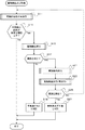
図1は、本発明の実施の形態に係る検査装置1の概略構成図である。図1において、検査装置1は、テスト対象物、例えばウエハ8を搬送するローダ部12と、ウエハ8の電気的特性検査を行うプローバ部15と、プローバ部15を介してウエハ8に形成された加速度センサの特性値を測定する検査制御部2とを備える。(Embodiment 1)
FIG. 1 is a schematic configuration diagram of an
ローダ部12は、例えば25枚のウエハ8が収納されたカセットを載置する載置部(図示せず)と、この載置部のカセットからウエハ8を一枚ずつ搬送するウエハ搬送機構とを備えている。
The
ウエハ搬送機構としては、直交する三軸(X軸、Y軸、Z軸)の移動機構であるX−Y−Zテーブル12A、12B、12Cを介して三軸方向に移動すると共に、Z軸の回りにウエハ8を回転させるメインチャック14とが設けられている。具体的には、Y方向に移動するYテーブル12Aと、このYテーブル12A上をX方向に移動するXテーブル12Bと、このXテーブル12Bの中心と軸芯を一致させて配置されたZ方向に昇降するZテーブル12Cとを有し、メインチャック14をX、Y、Z方向へ移動させる。また、メインチャック14は、Z軸回りの回転駆動機構を介して、所定の範囲で正逆方向に回転する。
The wafer transfer mechanism moves in three axes via XYZ tables 12A, 12B, and 12C, which are three orthogonal axes (X-axis, Y-axis, and Z-axis). A
プローバ部15は、プローブカード4とプローブカード4を制御するプローブ制御部13とを備える。プローブカード4は、ウエハ8上に例えば銅、銅合金、アルミニウムなどの導電性金属によって形成された電極パッド8a(図9参照)と検査用プローブ4aとを接触させ、フリッティング現象を利用して、電極パッド8aとプローブ4aの接触抵抗を低減させて電気的に導通させる。また、プローバ部15は、ウエハ8に形成された加速度センサ16(図9参照)の可動部16aに対して空気を噴出又は吸入する複数のノズル10(図2参照)を備える。プローブ制御部13は、プローブカード4のプローブ4aとノズル10に接続するノズル流量制御部を制御し、ウエハ8に形成された加速度センサ16に所定の変位を加えて、加速度センサ16の可動部16aの動きをプローブを介して電気信号として検出する。
The
プローバ部15は、プローブカード4のプローブ4aとウエハ8との位置合わせを行うアラインメント機構(図示せず)を備える。プローバ部15は、複数のノズル10(図9参照)の先端を、ウエハ8の加速度センサ16の可動部16aに対向して配置させ、ノズル10から気体を噴出又は吸入して、加速度センサ16の可動部16aに変位を与える。また、プローバ部15は、プローブカード4のプローブ4aとウエハ8の電極パッド8aを電気的に接触させてウエハ8に形成された加速度センサ16の特性値の測定を行う。
The
図2は、図1の検査装置1の検査制御部2とプローバ部15の構成を示すブロック図である。検査制御部2とプローバ部15とによって、加速度センサ評価測定回路が構成される。
FIG. 2 is a block diagram showing the configuration of the
検査制御部2は、図2に示すように、制御部21、主記憶部22、外部記憶部23、入力部24、入出力部25及び表示部26を備える。主記憶部22、外部記憶部23、入力部24、入出力部25及び表示部26はいずれも内部バス20を介して制御部21に接続されている。
As shown in FIG. 2, the
制御部21はCPU(Central Processing Unit)等から構成され、外部記憶部23に記憶されているプログラムに従って、ウエハ8に形成されたセンサの特性、例えば抵抗の抵抗値やセンサを構成する回路の電流、電圧などを測定するための処理を実行する。
The
主記憶部22はRAM(Random-Access Memory)等から構成され、外部記憶部23に記憶されているプログラムをロードし、制御部21の作業領域として用いられる。
The
外部記憶部23は、ROM(Read Only Memory)、フラッシュメモリ、ハードディスク、DVD−RAM(Digital Versatile Disc Random-Access Memory)、DVD−RW(Digital Versatile Disc Rewritable)等の不揮発性メモリから構成され、前記の処理を制御部21に行わせるためのプログラムを予め記憶し、また、制御部21の指示に従って、このプログラムが記憶するデータを制御部21に供給し、制御部21から供給されたデータを記憶する。
The
入力部24はキーボード及びマウスなどのポインティングデバイス等と、キーボード及びポインティングデバイス等を内部バス20に接続するインターフェース装置から構成されている。入力部24を介して、評価測定開始や測定方法の選択などが入力され、制御部21に供給される。
The
入出力部25は、検査制御部2が制御する対象のプローブ制御部13と接続するシリアルインタフェース又はLAN(Local Area Network)インタフェースから構成されている。入出力部25を介して、プローブ制御部13にウエハ8の電極パッド8aとの接触、電気的導通、それらの切替、及び加速度センサ16の可動部16aに対して噴出又は吸入する気体の流量の制御などを指令する。また、測定した結果を入力する。
The input /
表示部26は、CRT(Cathode Ray Tube)又はLCD(Liquid Crystal Display)などから構成され、測定した結果である周波数応答特性などを表示する。
The
プローブ制御部13は、ノズル流量制御部3と、フリッティング用回路5と、特性評価部6及び切替部7を備える。特性評価部6は、プローブカード4に加速度センサ16の電気信号を測定するための電源を供給し、加速度センサ16を流れる電流と端子間の電圧等を測定する。
The
ノズル流量制御部3は、ウエハ8に形成された加速度センサ16の可動部16a(図9参照)に変位を加えるために、ノズル10から噴出又は吸入する気体の流量を制御する。複数のノズル10から噴出又は吸入する気体の流量をそれぞれ制御して、加速度センサ16の可動部16aに所定の変位が加わるようにする。
The nozzle flow
フリッティング用回路5は、ウエハ8の電極パッド8aに接触させたプローブカード4のプローブ4aに電流を供給し、プローブ4aと電極パッド8aの間にフリッティング現象を起こして、プローブ4aと電極パッドの接触抵抗を低減させる回路である。
The
特性評価部6は、微小構造体の特性を計測して評価する。例えば、可動部16aに静的又は動的な変位を加えて、加速度センサ16の応答を測定し、設計した基準の範囲に収まっているかどうかを検査する。
The
切替部7は、プローブカード4の各プローブ4aとフリッティング用回路5又は特性評価部6との接続を切り替える。
The
本実施の形態に従う検査方法について説明する前にまずテスト対象物である微小構造体の3軸加速度センサ16について説明する。
Before describing the inspection method according to the present embodiment, first, the microstructure
図3は、3軸加速度センサ16のデバイス上面から見た図である。図3に示されるように、ウエハ8に形成されるチップTPには、複数の電極パッドPDがその周辺に配置されている。そして、電気信号を電極パッドPDに対して伝達、あるいは電極パッドPDから伝達するために、金属配線が設けられている。そして、中央部には、クローバ型を形成する4つの重錘体ARが配置されている。
FIG. 3 is a view of the
図4は、3軸加速度センサ16の概略図である。図4に示す3軸加速度センサ16はピエゾ抵抗型であり、検出素子であるピエゾ抵抗素子が拡散抵抗として設けられている。このピエゾ抵抗型の加速度センサ16は、安価なICプロセスを利用して製造できる。検出素子である抵抗素子を小さく形成しても感度低下がないため、小型化・低コスト化に有利である。
FIG. 4 is a schematic diagram of the
具体的な構成としては、中央の重錘体ARは、4本のビームBMで支持された構造となっている。ビームBMはX、Yの2軸方向で互いに直交するように形成されており、1軸当たりに4つのピエゾ抵抗素子を備えている。Z軸方向検出用の4つのピエゾ抵抗素子は、X軸方向検出用ピエゾ抵抗素子の横に配置されている。重錘体ARの上面形状はクローバ型を形成し、中央部でビームBMと連結されている。このクローバ型構造を採用することにより、重錘体ARを大きくすると同時にビーム長を長くすることができるため、小型であっても高感度な加速度センサ16を実現することが可能である。
As a specific configuration, the center weight AR is supported by four beams BM. The beam BM is formed so as to be orthogonal to each other in the X-axis and Y-axis directions, and includes four piezoresistive elements per axis. Four piezoresistive elements for detecting the Z-axis direction are arranged beside the piezoresistive elements for detecting the X-axis direction. The top surface shape of the weight body AR forms a clover shape, and is connected to the beam BM at the center. By adopting this crowbar type structure, the weight AR can be enlarged and the beam length can be increased at the same time, so that it is possible to realize a highly
このピエゾ抵抗型の3軸加速度センサ16の動作原理は、重錘体ARが加速度(慣性力)を受けると、ビームBMが変形し、その表面に形成されたピエゾ抵抗素子の抵抗値の変化により加速度を検出するメカニズムである。そしてこのセンサ出力は、3軸それぞれに独立に組み込まれたホイートストンブリッジの出力から取り出す構成に設定されている。
The principle of operation of the piezoresistive
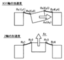
図5は、各軸方向の加速度を受けた場合の重錘体とビームの変形を説明する概念図である。図5に示されるようにピエゾ抵抗素子は、加えられたひずみによってその抵抗値が変化する性質(ピエゾ抵抗効果)を有しており、引っ張り歪みの場合は抵抗値が増加し、圧縮歪みの場合は抵抗値が減少する。本例においては、X軸方向用ピエゾ抵抗素子Rx1〜Rx4、Y軸方向検出用ピエゾ抵抗素子Ry1〜Ry4及びZ軸方向検出用ピエゾ抵抗素子Rz1〜Rz4が一例として示されている。 FIG. 5 is a conceptual diagram for explaining deformation of the weight body and the beam when acceleration in each axial direction is received. As shown in FIG. 5, the piezoresistive element has a property that its resistance value changes due to applied strain (piezoresistive effect). In the case of tensile strain, the resistance value increases, and in the case of compressive strain. The resistance value decreases. In this example, X-axis direction piezoresistive elements Rx1 to Rx4, Y-axis direction detecting piezoresistive elements Ry1 to Ry4, and Z-axis direction detecting piezoresistive elements Rz1 to Rz4 are shown as examples.
図6は、各軸に対して設けられるホイートストンブリッジの回路構成図である。図6(a)は、X(Y)軸におけるホイートストンブリッジの回路構成図である。X軸及びY軸の出力電圧としてはそれぞれVxout及びVyoutとする。図6(b)は、Z軸におけるホイートストンブリッジの回路構成図である。Z軸の出力電圧としてはVzoutとする。 FIG. 6 is a circuit configuration diagram of a Wheatstone bridge provided for each axis. FIG. 6A is a circuit configuration diagram of the Wheatstone bridge in the X (Y) axis. The output voltages of the X axis and Y axis are Vxout and Vyout, respectively. FIG. 6B is a circuit configuration diagram of the Wheatstone bridge in the Z-axis. The output voltage of the Z axis is Vzout.
上述したように、加えられた歪みによって各軸の4つのピエゾ抵抗素子の抵抗値は変化し、この変化に基づいて各ピエゾ抵抗素子は、例えばX軸Y軸においては、ホイートストンブリッジで形成される回路の出力各軸の加速度成分が独立に分離された出力電圧として検出される。なお、上記の回路が構成されるように図3で示されるような、金属配線等が連結され、所定の電極パッド8aから各軸に対する出力電圧が検出されるように構成されている。
As described above, the resistance values of the four piezoresistive elements on each axis change due to the applied strain. Based on this change, each piezoresistive element is formed by a Wheatstone bridge, for example, on the X axis and the Y axis. The acceleration component of each output axis of the circuit is detected as an independent output voltage. As shown in FIG. 3, metal wiring or the like is connected so that the above-described circuit is configured, and an output voltage for each axis is detected from a
また、この3軸加速度センサ16は、加速度の直流成分も検出することができるため、重力加速度を検出する傾斜角センサとしても用いることが可能である。本実施の形態では、加速度センサ16を例に説明するが、本発明は可動部16aを備えるあらゆるデバイスに応用することができる。例えば、圧力センサ等の動的な特性の測定に用いることができる。また、薄膜式のデバイス、例えば、ひずみゲージ等に変位を加えて特性の測定に用いることができる。
Further, since the
図7は、3軸加速度センサ16の傾斜角に対する出力応答を説明する図である。図7に示されるように、センサをX、Y、Z軸周りに回転させ、X、Y、Z軸それぞれのブリッジ出力をデジタルボルトメータで測定したものである。センサの電源としては低電圧電源+5Vを使用している。なお、図7に示される各測定点は、各軸出力のゼロ点オフセットを算術的に減じた値がプロットされている。
FIG. 7 is a diagram illustrating an output response to the tilt angle of the
図8は、重力加速度(入力)とセンサ出力との関係を説明する図である。図8に示される入出力関係は、図7の傾斜角の余弦からX、Y、Z軸にそれぞれ関わっている重力加速度成分を計算し、重力加速度(入力)とセンサ出力との関係を求めて、その入出力の線形性を評価したものである。すなわち加速度と出力電圧との関係はほぼ線形である。 FIG. 8 is a diagram for explaining the relationship between gravitational acceleration (input) and sensor output. The input / output relationship shown in FIG. 8 is to calculate the gravitational acceleration components related to the X, Y, and Z axes from the cosine of the inclination angle of FIG. 7 and obtain the relationship between the gravitational acceleration (input) and the sensor output. The linearity of the input / output is evaluated. That is, the relationship between acceleration and output voltage is almost linear.
再び図1及び図2を参照して、本発明の実施の形態における微小構造体の検査方法は、微小構造体である3軸加速度センサ16に対して、ノズル10によって空気流を加えることにより、その空気流に基づく微小構造体の可動部16aの動きを検出してその特性を評価する方式である。
Referring to FIGS. 1 and 2 again, in the microstructure inspection method in the embodiment of the present invention, an air flow is applied to the
次に、本発明の実施の形態における加速度センサ16の評価方法について説明する。図9は、ノズル10とウエハ8の構成を表す概念図である。ウエハ8は、可動部16aを備える加速度センサ16が形成されており、ウエハ8の上に加速度センサ16の電気信号を取り出すための電極パッド8aが形成されている。
Next, a method for evaluating the
プローブカード4は、電極パッド8aに接続する複数のプローブ4aを備える(図2)。検査装置1のプローバ部15は、加速度センサ16の可動部16aに対して空気流を発生するノズル流量制御部3と、可動部16aの近くに配置されてノズル流量制御部3の空気流を加速度センサ16の可動部16aに噴出又は吸入するノズル10を備える(図9)。
The
通常、プローブ4aと電気的に接続する検査用電極である電極パッド8aはセンサの周辺領域に形成される。そこで、センサの中央付近にある可動部16a(重錘体)の近傍にノズル10の先端が配置するように、プローブ4aで囲まれる領域にノズル10を設けることができる。可動部16aは、重錘体AR又はビームBM、あるいはセンサがメンブレン(膜)構造の場合の膜などである。
Usually, an
ノズル10は、空気を通す管でノズル流量制御部3の切替弁30に接続している。ノズル流量制御部3は、圧縮空気源33と真空源34を備える。圧縮空気源33と真空源34はそれぞれ流量コントローラA31、流量コントローラB32を経由して切替弁30に接続している。流量コントローラA31は、ノズル10から噴出する空気の流量を制御する。流量コントローラB32は、ノズル10から吸入する空気の流量を制御する。切替弁30は圧縮空気源33と真空源34を切り替えてノズル10に接続する。切替弁30で圧縮空気源33とノズル10を接続した場合は、ノズル10から空気が噴出する。切替弁30で真空源34とノズル10を接続した場合は、ノズル10から空気を吸入する。
The
複数のノズル10はそれぞれ別のノズル流量制御部3に接続している。複数のノズル10はそれぞれ独立に、空気の噴出又は吸入の切替えとその流量が制御される。複数のノズル10のそれぞれの噴出又は吸入の方向とその流量を組み合わせて、加速度センサ16の任意の自由度の方向に可動部16aを変位させることができる。ノズル10から噴出又は吸入する空気の流れは、一定に限ることはなく、変動させてもよい。例えば、1つのノズル10について、噴出と吸入を交互に切り替えることができる。また、噴出又は吸入の流量を脈動的に変化させて、可動部16aを振動的に変位させることができる。
The plurality of
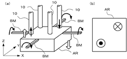
図10乃至図17は、ノズル10の噴出又は吸入の方向の組み合わせと可動部16aの変位の方向の例を示す概念図である。
10 to 17 are conceptual diagrams showing examples of combinations of ejection or suction directions of the
図10乃至図17において、可動部16aの重錘体ARはX軸とY軸の方向にビームBMで支持されている。クローバ型に配置された重錘体ARに対向して、4つのノズル10が配置されている。図中、実線の直線矢印はノズル10から噴出又は吸入する空気の方向を示す。白抜き矢印は、重錘体ARに加わる力を表す。円弧矢印は、ビームBMに加わる捩れ方向を表す。図10乃至図17の(b)は、重錘体ARをZ軸の正の方向から見た図である。図10乃至図17の(b)において、円に囲まれた黒丸は、紙面の裏面から表面へ向かう空気の流れを表す。また、円に囲まれた×印は、紙面の表面から裏面へ向かう空気の流れを表す。
10 to 17, the weight body AR of the
図10は、右の2つのノズル10から空気を吸入し、左の2つのノズル10から空気を噴出する場合を示す。重錘体ARの左側はZ軸負方向に変位し、右側はZ軸正方向に変位する。Y軸方向のビームBMは、Y軸を正の方向に見て反時計回りに捩れる。
FIG. 10 shows a case where air is sucked from the two
図11は、4本のノズル10から空気を噴出する場合を示す。4本のノズル10から均等に空気を噴出する場合は、重錘体ARは全体としてZ軸負方向に変位する。その場合、ビームBMには捩れが加わらない。4本のノズル10から噴出する流量に変化をつけると、重錘体ARは傾きながら全体としてZ軸負方向に変位する。
FIG. 11 shows a case where air is ejected from the four
図12は、1本のノズル10から空気を噴出し、他の3本のノズル10の空気の流量がない場合を示す。重錘体ARは全体としてZ軸負方向に変位するが、重錘体ARに対して加わる力が偏るので、Y軸方向のビームBMは、Y軸を正の方向に見て反時計回りに捩れ、X軸方向のビームBMは、X軸を正の方向に見て時計回りに捩れる。
FIG. 12 shows a case where air is ejected from one
図13は、2本のノズル10から空気を噴出し、他の2本のノズル10の空気の流量がない場合を示す。重錘体ARのX軸負側がZ軸負方向に押されるので、重錘体ARは全体としてZ軸負方向に変位するが、Y軸方向のビームBMは、Y軸を正の方向に見て反時計回りに捩れる。
FIG. 13 shows a case where air is ejected from the two
図14は、4本のノズル10から空気を吸入する場合を示す。4本のノズル10から均等に空気を吸入する場合は、重錘体ARは全体としてZ軸正方向に変位する。その場合、ビームBMには捩れが加わらない。4本のノズル10から吸入する流量に変化をつけると、重錘体ARは傾きながら全体としてZ軸正方向に変位する。
FIG. 14 shows a case where air is sucked from the four
重錘体ARの下面がウエハ8の下面と同じ平面にあって、ウエハ8の状態でチップTPを検査するとき、可動部16aをウエハ8の下面方向に変位できない場合がある。その場合、従来の空気を吹き付けて検査する方法では、可動部16aを変位させることができないが、本発明の方法では、ノズル10から空気を吸入して可動部16aを変位させることができる。
When the lower surface of the weight AR is on the same plane as the lower surface of the
図15は、1本のノズル10から空気を吸入し、他の3本のノズル10の空気の流量がない場合を示す。重錘体ARは全体としてZ軸正方向に変位するが、重錘体ARに対して加わる力が偏るので、Y軸方向のビームBMは、Y軸を正の方向に見て時計回りに捩れ、X軸方向のビームBMは、X軸を正の方向に見て反時計回りに捩れる。
FIG. 15 shows a case where air is sucked from one
図16は、2本のノズル10から空気を吸入し、他の2本のノズル10の空気の流量がない場合を示す。重錘体ARのX軸負側がZ軸正方向に吸引されるので、重錘体ARは全体としてZ軸正方向に変位するが、Y軸方向のビームBMは、Y軸を正の方向に見て時計回りに捩れる。
FIG. 16 shows a case where air is sucked from the two
図17は、重錘体ARの対角線に位置する2本のノズル10で、1本から空気を噴出し、他の1本から吸入する場合を示す。図17の場合、Y軸方向のビームBMは、Y軸を正の方向に見て時計回りに捩れ、X軸方向のビームBMは、X軸を正の方向に見て反時計回りに捩れる。噴出と吸入の流量を適当に調節すると、重錘体ARの重心は変位せず、捩れ方向の変位を加えることができる。
FIG. 17 shows a case where air is ejected from one nozzle and sucked from the other nozzle by two
図10乃至図17は、ノズル10の噴出又は吸入の組み合わせの例であって、これらの組み合わせに限定されるものではない。その他、任意の組み合わせが可能である。また、前述のとおり、ノズル10から噴出又は吸入する方向を切り替えたり、空気の流量を変動させてもよい。なお、1つの可動部16aに対してノズル10は4本に限られない。2本、3本、あるいは5本以上のノズル10を備えていてもよい。
FIGS. 10 to 17 are examples of combinations of ejection or suction of the
上記のとおり、複数のノズル10から可動部16aに対して気体を噴出又は吸入する方向と流量の組み合わせによって、可動部16aをさまざまな方向に変位させることができる。その結果、検査装置1で加速度センサ16の各自由度方向の特性を検査することができる。
As described above, the
加速度センサ16等のMEMSデバイスのように、可動部16aを有する微小構造体で、ピエゾ抵抗などを用いている場合は特に、プローブ4aの針圧によって応答特性が変化する。従って、センサ等の応答特性のように精度の高い計測を行うためには、可能な限り針圧等の外乱の影響をなくすことが望ましい。
When a piezoresistor or the like is used in a microstructure having a
プローブ4aと電極パッド8aの電気的接続には、接触抵抗を低く保ちながら針圧を小さくするためにフリッティング現象を利用する。フリッティング現象を利用するには、2本のプローブ4aを一対として、一つの電極パッド8aに接触させる。一対のプローブ4aと電極パッド8aを接触させたのち、プローブカード4をフリッティング用回路5に接続して、ウエハ8の電極パッド8aに接触させたプローブカード4のプローブ4aに電流を供給し、プローブ4aと電極パッド8aの間にフリッティング現象を起こして接触抵抗を低減させる。そして、切換部7を切り替えて、プローブカード4を特性評価部6に接続する。
The electrical connection between the
前述のとおり、検査装置1の検査制御部2は、プローバ部15のアラインメント機構を制御して、ウエハ8の電極パッド8aにプローブ4aを接触させる。同時に、ノズル10を加速度センサ16の可動部16aの近傍に配置する。
As described above, the
ついで、ノズル流量制御部3に指令して、ノズル10から空気を噴出又は吸入させると、空気の流れによって加速度センサ16の可動部16aに変位が加わる。加速度センサ16の可動部16aに変位を与えながら、プローブ4aで加速度センサ16の電気信号を検出し、加速度センサ16の特性を評価する。
Next, when the nozzle flow
加速度センサ16の特性を評価するには、可動部16aに加える変位の方向と大きさを所定の値になるように制御して、加速度センサ16の応答を検出する。可動部16aに加える変位の方向と大きさを変化させて加速度センサ16の応答を測定することにより、加速度センサ16の応答特性を調べることができる。可動部16aに加える変位に変動成分を加えてもよい。さらに、可動部16aに加える変位として、所定の周波数範囲で擬似的なホワイトノイズを用いてもよい。ホワイトノイズを振動として加えると、加振周波数を変えながら応答を調べなくても、その周波数範囲における応答特性を検査することができる。
In order to evaluate the characteristics of the
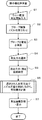
次に、本発明の実施の形態1に従う微小構造体の検査方法について説明する。図18は本発明の実施の形態に係る検査装置1の動作の一例を示すフローチャートである。なお、検査制御部2の動作は、制御部21が主記憶部22、外部記憶部23、入力部24、入出力部25及び表示部26と協働して行う。
Next, a microstructure inspection method according to the first embodiment of the present invention will be described. FIG. 18 is a flowchart showing an example of the operation of the
検査制御部2はまず、ウエハ8がメインチャック14に載置され、測定開始が入力されるのを待機する(ステップS1)。測定開始指令が入力部24から入力されて制御部21に指示されると、制御部21は、入出力部25を介して、プローブ制御部13にプローブ4aをウエハ8の電極パッド8aに接触するよう指令する(ステップS2)。同時に、ノズル10を加速度センサ16の可動部16aの近傍の所定の位置に配置する。ついで、プローブ制御部13にフリッティング用回路5によって、プローブ4aと電極パッド8aを導通させるように指令する(ステップS3)。
The
本実施の形態では、フリッティング現象を利用して電極パッド8aとプローブ4aの接触抵抗を低減させるが、接触抵抗を低減して導通させる方法としては、フリッティング技術以外の方法を利用してもよい。例えば、プローブ4aに超音波を伝導して、電極パッド8a表面の酸化膜を部分的に破って、電極パッド8aとプローブ4aの接触抵抗を低減させる方法を用いることができる。
In the present embodiment, the contact resistance between the
ついで、測定方法の選択を入力する(ステップS4)。測定方法は、予め外部記憶部23に記憶されていてもよいし、測定の都度、入力部24から入力されてもよい。測定方法が入力されると、入力された測定方法によって用いる測定回路、及び可動部16aに印加する変位の方向と大きさ(及び周波数など)を設定する(ステップ5)。
Next, the selection of the measurement method is input (step S4). The measurement method may be stored in advance in the
選択される測定方法としては、例えば、加速度センサ16の各自由度方向の独立した平行変位、各自由度方向の独立した捩れ変位、各自由度方向の組み合わせ変位、各自由度方向の捩れの組み合わせ変位などがある。また、変位の周波数を順次変化させてそれぞれの周波数での応答を検査する周波数掃引検査(周波数スキャン)、所定の周波数範囲の擬似ホワイトノイズを印加して応答を検査するホワイトノイズ検査、周波数を所定の値に固定して変位の振幅を変化させて応答を検査する直線性検査などがある。
As the measurement method to be selected, for example, independent parallel displacement in each degree of freedom direction of the
ついで、設定した測定方法でノズル流量制御部3を制御して、加速度センサ16の可動部16aを変位させながら、プローブ4aから加速度センサ16の応答である電気信号を検出し、加速度センサ16の応答特性を検査する(ステップS6)。そして、検出した測定結果を外部記憶部23に記憶すると同時に、表示部26に測定結果を表示する(ステップS7)。
Next, the nozzle
加速度センサ16の可動部16aは、加速度センサ16の近傍に配置される複数のノズル10から噴出又は吸入する気体の流れによって変位されるため、複数の自由度を有するセンサでも、自由度ごとに又は自由度方向を組み合わせて検査を行うことができる。また、空気を吹き付けて可動部16aの変位を検査する方法に比べて、可動部16aを吸引する方向に変位を加えることができるので、ウエハ8の状態で可動部16aの変位方向に制約がある場合でも、ウエハ8上で検査することができる。
Since the
(実施の形態1の変形例)
図19は、プローブ4aとノズル10の異なる構成を示す図である。図19の例では、プローブカード4に複数のノズル10を設けた構造になっている。プローブ4aとノズル10の配置を予め調整しておく。プローブ4aを電極パッド8aに接触させるよう位置決めすることによって、同時にノズル10が可動部16aに対して所定の位置に配置される。ノズル10をプローブ4aと独立に位置決め制御する必要がない。その結果、既存の検査装置の位置決め機構を利用して、複数のノズル10による変位を加えて微小構造体の特性を検査することができる。(Modification of Embodiment 1)
FIG. 19 is a diagram illustrating different configurations of the
(実施の形態1の変形例2)
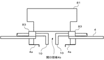
図20は、本発明の実施の形態1の変形例2に従うプローブカードの構造を説明する図である。(
FIG. 20 is a diagram illustrating the structure of the probe card according to the second modification of the first embodiment of the present invention.
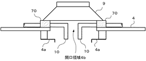
図20に示すプローブカード4は、変形例1のプローブカード4に加えてさらに、テスト音波を出力するスピーカ9を備える。スピーカ9が出力するテスト音波は、開口領域4bを通って、可動部16aに加えられる。テスト音波によって、微小構造体、たとえば加速度センサ16の可動部16aが振動する。テスト音波によって可動部16aを振動させながら、加速度センサ16の信号を検出し、加速度センサ16の周波数特性を検査することができる。
The
ノズル10の空気流を変動させることによって、ある範囲で周波数特性を検査することが可能である。スピーカ9のテスト音波と組み合わせて、一定変位(直流成分)から高い周波数まで連続して周波数特性を検査することができる。あるいは、ノズル10の空気流によって一定変位を与えながら、スピーカ9のテスト音波による振動を加えて、周波数特性の変化を検査するなどの複合検査を行うことができる。
By varying the air flow of the
スピーカ9は、プローブカード4に対して支持部材により支持されており、支持部材を防振材料(防振材)70で形成することができる。防振材料70の間をノズル10が貫通している。防振材料70で支持することより、スピーカ9からの振動をプローブカード4に伝達するのを防止し、精度の高い検査を実行することができる。防振材料70としては、シリコンゴムあるいは樹脂等を用いることが可能である。
The speaker 9 is supported by a support member with respect to the
さらに、開口領域4bの周辺などにマイク(図示せず)を設けて、スピーカ9から加速度センサ16に対して加えられるテスト音波を検出してもよい。マイクで検出する音響信号が所定の周波数特性になるように、スピーカ9から出力するテスト音波を制御する。それによって、可動部16aに所定の周波数特性のテスト音波を加えることができる。
Furthermore, a microphone (not shown) may be provided around the opening region 4b to detect a test sound wave applied from the speaker 9 to the
(実施の形態1の変形例3)
図21は、本発明の実施の形態1の変形例3における、本発明の実施の形態に係る検査装置1の動作の一例を示すフローチャートである。該動作は、加速度センサ16にチリやホコリ等の異物が付着している場合に、ノズル10から噴出又は吸入される気体により該異物を吹き飛ばしたり吸い取ったりする動作である。(
FIG. 21 is a flowchart showing an example of the operation of the
本フローチャートに示される動作は、図18のフローチャートに示される微小構造体検査(主にステップ6)において、必要に応じて随時実行される。 The operation shown in this flowchart is executed as needed in the microstructure inspection (mainly step 6) shown in the flowchart of FIG.
加速度センサ16に異物が付着している場合、可動部16aが全く又はほとんど動かないときがある。このとき、該センサが元々不良品である可能性と、単に異物による可動部16a近傍の目詰まり等が起きているだけである可能性と、の両方の可能性が考えられる。以下では、前者に対応する加速度センサ16を元来の不良品と呼び、後者に対応するセンサを見かけ上の不良品と呼ぶことにする。
When a foreign object adheres to the
可動部16aが全く又はほとんど動かないことをもって、直ちに一律に、該可動部を有する加速度センサ16は不良品である、とする判別基準が採用された検査においては、実は見かけ上の不良品であっても、元来の不良品と区別されることなく、不良品であると結論されてしまう。
In the inspection using the discrimination criterion that the
一方、本発明の実施の形態に係る検査装置1はノズル10を備えており、該ノズルにより気体が噴出又は吸入される。既に詳細に述べたとおり、かかる気体の噴出又は吸入は、本来、可動部16aに変位を与えるために行われるものである。しかし、かかる気体の噴出又は吸入のための機構を、加速度センサ16に付着した異物の除去の目的に転用することも可能である。
On the other hand, the
すなわち、本発明の実施の形態に係る検査装置1は、検査と並行して、加速度センサ16に付着した異物の除去という、一種の清掃作業を行うことができる潜在的能力を有している。かかる清掃作業により、見かけ上の不良品のうち、例えばごく軽いホコリが可動部16aの近傍に単にはさまっただけのものは、該ホコリが除去される結果、不良品扱いを免れ得る。換言すれば、本変形例によれば、従来なら元来の不良品と区別されることなく一律に不良品扱いされていた見かけ上の不良品のうち、少なくとも一部は、不良品扱いを免れることが期待される。よって、本変形例によれば、加速度センサ16の製造における歩留まりが向上することが期待される。
In other words, the
ここまで、可動部16aが全く又はほとんど動かないときについて述べてきた。これは、より厳密には、可動部16aに変位を与えるための気体の流れがノズル10により生成された(図21のステップS11)にもかかわらず、該可動部に、該流れの強度から予期される程度の変位が生じなかったことを意味する。具体的には、前記流れの強度に応じて生じるべき変位について、最低値があらかじめ定められていて、該最低値を閾値として、変位についての判別がなされる(ステップS13)。変位が該閾値以下のものは原則としては不良品とされる(ステップS13;YesかつステップS17;No)。一方、変位が該閾値を上回った場合は(ステップS13;No)、少なくとも本動作においては、不良品扱いを免れる。
So far, the case where the
本変形例の特徴は、ステップS13において可動部16aの変位が所定の閾値以下であると判別(ステップS13;Yes)されて以降の手順にある。すなわち、本変形例の場合、検査制御部2は、可動部16aの周りに、試しに、ノズル10により所定の強度の気体の流れを発生させてみる(ステップS11)。そして、検査制御部2は、プローブ4aを介して、可動部16aに前記気体の流れの強度に見合うだけの変位が生じたか否かを判別する(ステップS13)。その際、判別の基準として、所定の閾値が用いられる。可動部の変位が所定の閾値を上回っていると判別された場合(ステップS13;No)、図21のフローチャートで示される異物検出及び除去の動作の範囲内に限っては、検査対象の加速度センサ16は不良品であるとは判別されないまま、処理は終了する。
The feature of this modification is in the procedure after it is determined in step S13 that the displacement of the
一方、可動部16aの変位が所定の閾値以下であると判別された場合(ステップS13;Yes)でも、本変形例においては、検査制御部2は、検査対象の加速度センサ16を直ちには不良品であると判別せず、まずは、該センサに異物が付着している可能性を探る。具体的には、検査制御部2は、例えば後述のカメラ81、カメラ制御部85、及び、画像解析部87を用いて、異物の検出を試みる(ステップS15)。
On the other hand, even when it is determined that the displacement of the
検査制御部2は、異物を検出したか否かを判別する(ステップS17)。異物を検出しなかったと判別された場合(ステップS17;No)、検査制御部2は、検査対象の加速度センサ16が元来の不良品であると判別し(ステップS19)、処理を終了する。
The
一方、異物を検出したと判別された場合(ステップS17;Yes)、検査制御部2は、異物除去を試みる(ステップS21)。具体的には、検査制御部2は、後述の画像解析部87による解析結果に基づいて、ノズル10により気体の流れを生成して、異物を吹き飛ばしたり吸い取ったりすることを試みる。
On the other hand, when it is determined that a foreign object has been detected (step S17; Yes), the
特に、本発明の実施の形態に係る検査装置1は、複数のノズルを備えている。よって、画像解析により異物の位置を判定して、該位置に集中的に、しかも様々な向きに気体の流れを生成して、異物除去を試みることが可能である。これにより、加速度センサ16に単に漫然と気体を吹き当てる等の手法に比べて、異物を除去する効率が向上する。
In particular, the
検査制御部2は、続いて、異物検出を試みる(ステップS23)。この試行は、実質的には、ステップS15の再試行である。検査制御部2はかかる再試行の結果異物を検出したか否かを判別する(ステップS25)。この判別は、ステップS17と同じ判別である。
The
なおも異物を検出したと判別された場合とは(ステップS25;Yes)、ノズル10により生成された気体の流れによっては、異物を除去できないということである。よって、検査制御部2は、検査対象の加速度センサ16を、異物除去不可能と判別し(ステップS27)、処理を終了する。
The case where it is determined that a foreign object has been detected (step S25; Yes) means that the foreign object cannot be removed depending on the flow of gas generated by the
なお、このステップS27で異物除去不可能と判別された加速度センサは、異物が付着しているもののその除去ができなかったものであるから、元来の不良品であるかそれとも見かけ上の不良品であるかが結論されておらず、この意味で一種の保留状態にあるといえる。よって、ステップS19が意味する、元来の不良品であるとの結論とは、区別されるのが妥当である。また、検査制御部2は、このように区別して例えば外部記憶部23に記録を残しておくことにより、上述の保留状態にある加速度センサ16については、後に別の手法により再度異物除去試行をする余地を残すことができる。
Note that the acceleration sensor determined to be unable to remove foreign matter in step S27 has foreign matter attached but could not be removed, so it is an original defective product or an apparent defective product. In this sense, it can be said that there is a kind of holding state. Therefore, it is appropriate to distinguish from the conclusion of step S19 that the product is originally defective. In addition, the
一方、もはや異物を検出しないと判別された場合(ステップS25;No)、ステップS11に戻り、可動部16aに変位を与えることを再度試みる。その後再びステップS13で該変位が不十分か否かが判別される。変位が十分であると判別された場合(ステップS13;No)、処理を終了する。これは、異物除去試行(ステップS21)により異物が実際に除去され、その結果加速度センサ16が正常に動作するようになったということである。つまり該センサは当初は見かけ上の不良品であったということである。一方、変位が不十分であると判別された場合(ステップS13;Yes)、念のため3回目の異物検出試行及び判別(ステップS15及びステップS17)が行われるが、既にステップS25で異物を検出しなかったと判別されているため、ステップS25からステップS17に至るごく短い時間に新たな異物が付着した等の特別な事情がない限り、異物を検出しないと判別され(ステップS17;No)、元来の不良品であると判別されてから(ステップS19)、処理が終了する。
On the other hand, when it is determined that no foreign matter is detected anymore (step S25; No), the process returns to step S11 to try again to give displacement to the
図22に、加速度センサ16aへの異物の付着状況を観察するためのカメラ81の設置方法の一例を模式的に示す。カメラ81は、図20のスピーカ9がカメラ81に置換されたような態様で、プローブカード4に支持部83を介して設置される。
FIG. 22 schematically shows an example of a method of installing the
なお、図22はあくまでも模式図であって、実際にカメラ81の本体が図示するように設置される必要はない。重要なのは開口領域4bを通じて加速度センサ16が観察され得るという点であって、実際に支持部83に接続されるのは例えばファイバースコープであってもよい。あるいは、プローブカード4とは独立して、カメラ81によりウエハ8全体の観察をする態様としてもよい。
Note that FIG. 22 is a schematic diagram to the last, and it is not necessary that the main body of the
図23は、本変形例における検査装置1の検査制御部2とプローバ部15の構成を示すブロック図である。描画の都合上一部の機能ブロックの位置をずらしたが、基本的には、図2に示したブロック図に、カメラ81、カメラ制御部85、及び、画像解析部87が追加されたものである。
FIG. 23 is a block diagram illustrating configurations of the
カメラ制御部85は、カメラ81と直接的に接続されて、カメラ81の位置決めや、撮影指令送信や、画像取得等を行う。画像解析部87は、カメラ制御部85がカメラ81から取得した画像に基づいて、異物検出のための画像解析を行う。カメラ制御部85及び画像解析部87は、検査制御部2内の入出力部25と、データや命令等の授受を行う。
The
なお、図23においては画像解析部87は検査制御部2の外側に描かれているが、画像解析部87は、検査制御部2内の外部記憶部23にプログラムとして格納されてもよい。そして、制御部21が、必要に応じて該プログラムを読み出して実行することにより、画像解析部87として機能するようにしてもよい。
In FIG. 23, the
その他、前記のハードウエア構成やフローチャートは一例であり、任意に変更及び修正が可能である。ノズル10から噴出又は吸入する気体は、空気以外に、検査装置1内部の雰囲気として必要な気体、例えば窒素などを用いてもよい。
In addition, the hardware configuration and the flowchart described above are merely examples, and can be arbitrarily changed and modified. As the gas ejected or sucked from the
検査装置1の検査制御部2は、専用のシステムによらず、通常のコンピュータシステムを用いて実現可能である。例えば、前記の動作を実行するためのコンピュータプログラムを、コンピュータが読みとり可能な記録媒体(フレキシブルディスク、CD-ROM、DVD-ROM等)に格納して配布し、当該コンピュータプログラムをコンピュータにインストールすることにより、前記の処理を実行する検査制御部2を構成してもよい。また、インターネット等の通信ネットワーク上のサーバ装置が有する記憶装置に当該コンピュータプログラムを格納しておき、通常のコンピュータシステムがダウンロード等することで本発明の検査制御部2を構成してもよい。
The
また、前記の各機能を、OS(オペレーティングシステム)とアプリケーションプログラムの分担、またはOSとアプリケーションプログラムとの協働により実現する場合などには、アプリケーションプログラム部分のみを記録媒体や記憶装置に格納してもよい。 When each of the above functions is realized by sharing an OS (operating system) and an application program, or by cooperation between the OS and the application program, only the application program portion is stored in a recording medium or a storage device. Also good.
また、搬送波に上述のコンピュータプログラムを重畳し、通信ネットワークを介して配信することも可能である。 It is also possible to superimpose the above computer program on a carrier wave and distribute it via a communication network.
今回開示された実施の形態はすべての点で例示であって制限的なものではないと考えられるべきである。本発明の範囲は上記の説明ではなくて特許請求の範囲によって示され、特許請求の範囲と均等の意味および範囲内でのすべての変更が含まれることが意図される。 The embodiment disclosed this time should be considered as illustrative in all points and not restrictive. The scope of the present invention is defined by the terms of the claims, rather than the description above, and is intended to include any modifications within the scope and meaning equivalent to the terms of the claims.
本出願は、2006年4月26日に出願された、日本国特許出願2006−122160号に基づく。本明細書中に日本国特許出願2006−122160号の明細書、特許請求の範囲、図面全体を参照として取り込むものとする。 This application is based on Japanese Patent Application No. 2006-122160 filed on Apr. 26, 2006. In this specification, the specification of Japanese Patent Application No. 2006-122160, the claims, and the entire drawing are incorporated as references.
複数のノズルを用いて気体の流れを精密に制御することができ、該流れにより微小構造体の可動部を自在に変位させることにより、様々な製造過程にある微小構造体を検査する用途にも適用できる。 The flow of gas can be precisely controlled by using multiple nozzles, and the movable part of the microstructure can be freely displaced by the flow, so that it can be used for inspecting microstructures in various manufacturing processes. Applicable.
Claims (10)
前記微小構造体の電気信号を取り出すために、前記微小構造体に形成された検査用電極に電気的に接続するプローブと、
前記微小構造体の可動部の近傍に配置され、気体を噴出又は吸入する複数のノズルと、
前記複数のノズルから噴出又は吸入する気体の流量を制御する気体流量制御手段と、
前記複数のノズルから噴出又は吸入する気体によって印加された前記微小構造体の可動部の変位を、前記プローブを介して得られる電気信号によって検出し、検出結果に基づいて前記微小構造体の特性を評価する評価手段と、
を備えることを特徴とする微小構造体の検査装置。A microstructure inspection apparatus for evaluating the characteristics of at least one microstructure having a movable part formed on a substrate,
A probe electrically connected to an inspection electrode formed on the microstructure in order to extract an electrical signal of the microstructure;
A plurality of nozzles that are arranged in the vicinity of the movable portion of the microstructure, and jet or suck gas;
Gas flow rate control means for controlling the flow rate of the gas ejected or sucked from the plurality of nozzles;
The displacement of the movable portion of the microstructure applied by the gas ejected or sucked from the plurality of nozzles is detected by an electrical signal obtained via the probe, and the characteristics of the microstructure are determined based on the detection result. An evaluation means to evaluate;
An inspection apparatus for a micro structure, comprising:
前記プローブと、
前記複数のノズルと、
を含むプローブカードを備える請求項1に記載の微小構造体の検査装置。A probe card connected to the evaluation means,
The probe;
The plurality of nozzles;
The micro structure inspection apparatus according to claim 1, further comprising a probe card including:
前記複数のノズルから噴出又は吸入する気体の流量を制御することにより、前記微小構造体に付着した異物を除去する、
ことを特徴とする請求項1に記載の微小構造体の検査装置。The gas flow rate control means includes
By controlling the flow rate of the gas ejected or sucked from the plurality of nozzles, foreign matter adhering to the microstructure is removed,
The micro structure inspection apparatus according to claim 1.
前記微小構造体に付着した異物を検出する異物検出手段
をさらに含み、
前記気体流量制御手段は、前記異物検出手段により前記異物が検出された場合には、前記複数のノズルから噴出又は吸入する気体の流量を制御することにより、前記微小構造体に付着した異物を除去する、
ことを特徴とする請求項2に記載の微小構造体の検査装置。The probe card is
A foreign matter detection means for detecting foreign matter attached to the microstructure,
The gas flow rate control means removes foreign matter adhering to the microstructure by controlling the flow rate of gas ejected or sucked from the plurality of nozzles when the foreign matter detection means detects the foreign matter. To
The micro structure inspection apparatus according to claim 2, wherein:
画像解析手段により前記異物の有無及び位置を判別する、
ことを特徴とする請求項6に記載の微小構造体の検査装置。The foreign object detection means includes
The presence / absence and position of the foreign matter is determined by image analysis means.
The micro structure inspection apparatus according to claim 6.
前記微小構造体の可動部を変位させるために、気体を噴出又は吸入するノズルを前記微小構造体の近傍に配置させるステップと、
前記複数のノズルから気体を噴出又は吸入して前記微小構造体の可動部を変位させるステップと、
前記複数のノズルから噴出又は吸入する気体によって印加された前記微小構造体の可動部の変位を、前記プローブを介して得られる電気信号によって検出するステップと、
前記電気信号によって検出した可動部の変位に基づいて前記微小構造体の特性を評価するステップと、
を備えることを特徴とする微小構造体の検査方法。Contacting a probe with a pad formed on the microstructure to extract an electrical signal of at least one microstructure having a movable portion formed on a substrate;
Disposing a nozzle for ejecting or sucking gas in the vicinity of the microstructure in order to displace the movable part of the microstructure;
Displacing the movable part of the microstructure by ejecting or sucking gas from the plurality of nozzles; and
Detecting the displacement of the movable part of the microstructure applied by the gas ejected or sucked from the plurality of nozzles by an electrical signal obtained through the probe;
Evaluating the characteristics of the microstructure based on the displacement of the movable part detected by the electrical signal;
A method for inspecting a micro structure characterized by comprising:
Applications Claiming Priority (3)
| Application Number | Priority Date | Filing Date | Title |
|---|---|---|---|
| JP2006122160 | 2006-04-26 | ||
| JP2006122160 | 2006-04-26 | ||
| PCT/JP2007/058069 WO2007125756A1 (en) | 2006-04-26 | 2007-04-12 | Apparatus for inspecting fine structure and method for inspecting fine structure |
Publications (1)
| Publication Number | Publication Date |
|---|---|
| JPWO2007125756A1 true JPWO2007125756A1 (en) | 2009-09-10 |
Family
ID=38655289
Family Applications (1)
| Application Number | Title | Priority Date | Filing Date |
|---|---|---|---|
| JP2008513136A Pending JPWO2007125756A1 (en) | 2006-04-26 | 2007-04-12 | Micro structure inspection apparatus and micro structure inspection method |
Country Status (5)
| Country | Link |
|---|---|
| US (1) | US20090039908A1 (en) |
| JP (1) | JPWO2007125756A1 (en) |
| KR (1) | KR101019080B1 (en) |
| TW (1) | TW200806967A (en) |
| WO (1) | WO2007125756A1 (en) |
Families Citing this family (9)
| Publication number | Priority date | Publication date | Assignee | Title |
|---|---|---|---|---|
| DE102007059279B3 (en) * | 2007-12-08 | 2010-01-21 | X-Fab Semiconductor Foundries Ag | Device for testing the mechanical-electrical properties of microelectromechanical sensors (MEMS) |
| JP5038191B2 (en) * | 2008-03-04 | 2012-10-03 | 有限会社共同設計企画 | Electronic component inspection method and apparatus used therefor |
| JP4491513B1 (en) * | 2009-02-12 | 2010-06-30 | 株式会社アドバンテスト | Semiconductor wafer testing equipment |
| WO2012098901A1 (en) * | 2011-01-20 | 2012-07-26 | パナソニック株式会社 | Acceleration sensor |
| TWI460402B (en) * | 2011-08-17 | 2014-11-11 | Hon Tech Inc | Electronic unit testing machine |
| EP2977811A1 (en) * | 2014-07-25 | 2016-01-27 | Trumpf Laser Marking Systems AG | System with a piezoresistive position sensor |
| US9527731B2 (en) * | 2014-10-15 | 2016-12-27 | Nxp Usa, Inc. | Methodology and system for wafer-level testing of MEMS pressure sensors |
| US10605831B2 (en) * | 2017-10-05 | 2020-03-31 | International Business Machines Corporation | Tool for automatically replacing defective pogo pins |
| US11047880B2 (en) | 2019-01-16 | 2021-06-29 | Star Technologies, Inc. | Probing device |
Citations (12)
| Publication number | Priority date | Publication date | Assignee | Title |
|---|---|---|---|---|
| JPS6232332A (en) * | 1985-08-05 | 1987-02-12 | Toyota Central Res & Dev Lab Inc | Method and device for testing pressure detecting element |
| JPS62170543U (en) * | 1986-04-21 | 1987-10-29 | ||
| JPH0534371A (en) * | 1991-07-31 | 1993-02-09 | Tokai Rika Co Ltd | Measuring apparatus for sensitivity of semiconductor acceleration sensor |
| JPH0774219A (en) * | 1993-08-31 | 1995-03-17 | Kurisutaru Device:Kk | Probe substrate, its manufacture and probe device |
| JPH0933567A (en) * | 1995-07-21 | 1997-02-07 | Akebono Brake Ind Co Ltd | Method and device for inspecting sensor chip of semiconductor acceleration sensor |
| JPH10123172A (en) * | 1996-10-21 | 1998-05-15 | Fuji Electric Co Ltd | Method and device for calibrating physical quantity sensor |
| JPH11218548A (en) * | 1998-02-03 | 1999-08-10 | Mitsubishi Electric Corp | Probe card |
| JP2001033506A (en) * | 1999-07-27 | 2001-02-09 | Hioki Ee Corp | Substrate inspecting device |
| JP2001264185A (en) * | 2000-03-21 | 2001-09-26 | Nikon Corp | Method and instrument for measuring internal stress of membrane of reticle and method for manufacturing semiconductor device |
| JP2003273174A (en) * | 2002-03-12 | 2003-09-26 | Seiko Instruments Inc | Semiconductor inspection device |
| JP2004191208A (en) * | 2002-12-12 | 2004-07-08 | Tokyo Electron Ltd | Inspection method and inspection device |
| JP2005286050A (en) * | 2004-03-29 | 2005-10-13 | Sharp Corp | Inspection method and device of semiconductor wafer |
Family Cites Families (2)
| Publication number | Priority date | Publication date | Assignee | Title |
|---|---|---|---|---|
| US6232790B1 (en) * | 1999-03-08 | 2001-05-15 | Honeywell Inc. | Method and apparatus for amplifying electrical test signals from a micromechanical device |
| JP4573794B2 (en) * | 2005-03-31 | 2010-11-04 | 東京エレクトロン株式会社 | Probe card and microstructure inspection device |
-
2006
- 2006-04-12 US US12/282,744 patent/US20090039908A1/en not_active Abandoned
-
2007
- 2007-04-12 WO PCT/JP2007/058069 patent/WO2007125756A1/en active Application Filing
- 2007-04-12 JP JP2008513136A patent/JPWO2007125756A1/en active Pending
- 2007-04-12 KR KR1020087020119A patent/KR101019080B1/en not_active IP Right Cessation
- 2007-04-13 TW TW096113039A patent/TW200806967A/en not_active IP Right Cessation
Patent Citations (12)
| Publication number | Priority date | Publication date | Assignee | Title |
|---|---|---|---|---|
| JPS6232332A (en) * | 1985-08-05 | 1987-02-12 | Toyota Central Res & Dev Lab Inc | Method and device for testing pressure detecting element |
| JPS62170543U (en) * | 1986-04-21 | 1987-10-29 | ||
| JPH0534371A (en) * | 1991-07-31 | 1993-02-09 | Tokai Rika Co Ltd | Measuring apparatus for sensitivity of semiconductor acceleration sensor |
| JPH0774219A (en) * | 1993-08-31 | 1995-03-17 | Kurisutaru Device:Kk | Probe substrate, its manufacture and probe device |
| JPH0933567A (en) * | 1995-07-21 | 1997-02-07 | Akebono Brake Ind Co Ltd | Method and device for inspecting sensor chip of semiconductor acceleration sensor |
| JPH10123172A (en) * | 1996-10-21 | 1998-05-15 | Fuji Electric Co Ltd | Method and device for calibrating physical quantity sensor |
| JPH11218548A (en) * | 1998-02-03 | 1999-08-10 | Mitsubishi Electric Corp | Probe card |
| JP2001033506A (en) * | 1999-07-27 | 2001-02-09 | Hioki Ee Corp | Substrate inspecting device |
| JP2001264185A (en) * | 2000-03-21 | 2001-09-26 | Nikon Corp | Method and instrument for measuring internal stress of membrane of reticle and method for manufacturing semiconductor device |
| JP2003273174A (en) * | 2002-03-12 | 2003-09-26 | Seiko Instruments Inc | Semiconductor inspection device |
| JP2004191208A (en) * | 2002-12-12 | 2004-07-08 | Tokyo Electron Ltd | Inspection method and inspection device |
| JP2005286050A (en) * | 2004-03-29 | 2005-10-13 | Sharp Corp | Inspection method and device of semiconductor wafer |
Also Published As
| Publication number | Publication date |
|---|---|
| TW200806967A (en) | 2008-02-01 |
| KR101019080B1 (en) | 2011-03-07 |
| TWI331676B (en) | 2010-10-11 |
| US20090039908A1 (en) | 2009-02-12 |
| WO2007125756A1 (en) | 2007-11-08 |
| KR20080088638A (en) | 2008-10-02 |
Similar Documents
| Publication | Publication Date | Title |
|---|---|---|
| JPWO2007125756A1 (en) | Micro structure inspection apparatus and micro structure inspection method | |
| KR101011491B1 (en) | Microstructure inspecting apparatus, microstructure inspecting method and substrate holding apparatus | |
| JP4573794B2 (en) | Probe card and microstructure inspection device | |
| JP4387987B2 (en) | Microstructure inspection apparatus, microstructure inspection method, and microstructure inspection program | |
| JPWO2006106876A1 (en) | MICROSTRUCTURE PROBE CARD, MICROSTRUCTURE INSPECTION DEVICE, INSPECTION METHOD, AND COMPUTER PROGRAM | |
| WO2006030716A1 (en) | Microstructure inspecting apparatus and microstructure inspecting method | |
| TWI300844B (en) | ||
| JP4856426B2 (en) | Micro structure inspection apparatus and micro structure inspection method | |
| JP2010048599A (en) | Device and method for inspecting minute structure | |
| TWI338138B (en) | ||
| JPWO2007018186A1 (en) | Microstructure inspection apparatus, inspection method, and inspection program | |
| JP2010048597A (en) | Apparatus and method for inspecting minute structure | |
| JP4822846B2 (en) | Microstructure inspection apparatus, microstructure inspection method, and microstructure inspection program | |
| JP2006284553A (en) | Device for inspecting micro structure, method for inspecting micro structure, and program for inspecting micro structure |
Legal Events
| Date | Code | Title | Description |
|---|---|---|---|
| A131 | Notification of reasons for refusal |
Free format text: JAPANESE INTERMEDIATE CODE: A131 Effective date: 20110315 |
|
| A02 | Decision of refusal |
Free format text: JAPANESE INTERMEDIATE CODE: A02 Effective date: 20110726 |