JPWO2005041338A1 - Saddle riding vehicle - Google Patents
Saddle riding vehicle Download PDFInfo
- Publication number
- JPWO2005041338A1 JPWO2005041338A1 JP2005514949A JP2005514949A JPWO2005041338A1 JP WO2005041338 A1 JPWO2005041338 A1 JP WO2005041338A1 JP 2005514949 A JP2005514949 A JP 2005514949A JP 2005514949 A JP2005514949 A JP 2005514949A JP WO2005041338 A1 JPWO2005041338 A1 JP WO2005041338A1
- Authority
- JP
- Japan
- Prior art keywords
- fuel
- aqueous solution
- tank
- seat
- solution tank
- Prior art date
- Legal status (The legal status is an assumption and is not a legal conclusion. Google has not performed a legal analysis and makes no representation as to the accuracy of the status listed.)
- Pending
Links
Images


Classifications
-
- H—ELECTRICITY
- H01—ELECTRIC ELEMENTS
- H01M—PROCESSES OR MEANS, e.g. BATTERIES, FOR THE DIRECT CONVERSION OF CHEMICAL ENERGY INTO ELECTRICAL ENERGY
- H01M8/00—Fuel cells; Manufacture thereof
- H01M8/10—Fuel cells with solid electrolytes
- H01M8/1009—Fuel cells with solid electrolytes with one of the reactants being liquid, solid or liquid-charged
- H01M8/1011—Direct alcohol fuel cells [DAFC], e.g. direct methanol fuel cells [DMFC]
-
- B—PERFORMING OPERATIONS; TRANSPORTING
- B62—LAND VEHICLES FOR TRAVELLING OTHERWISE THAN ON RAILS
- B62M—RIDER PROPULSION OF WHEELED VEHICLES OR SLEDGES; POWERED PROPULSION OF SLEDGES OR SINGLE-TRACK CYCLES; TRANSMISSIONS SPECIALLY ADAPTED FOR SUCH VEHICLES
- B62M7/00—Motorcycles characterised by position of motor or engine
- B62M7/12—Motorcycles characterised by position of motor or engine with the engine beside or within the driven wheel
-
- H—ELECTRICITY
- H01—ELECTRIC ELEMENTS
- H01M—PROCESSES OR MEANS, e.g. BATTERIES, FOR THE DIRECT CONVERSION OF CHEMICAL ENERGY INTO ELECTRICAL ENERGY
- H01M16/00—Structural combinations of different types of electrochemical generators
- H01M16/003—Structural combinations of different types of electrochemical generators of fuel cells with other electrochemical devices, e.g. capacitors, electrolysers
- H01M16/006—Structural combinations of different types of electrochemical generators of fuel cells with other electrochemical devices, e.g. capacitors, electrolysers of fuel cells with rechargeable batteries
-
- H—ELECTRICITY
- H01—ELECTRIC ELEMENTS
- H01M—PROCESSES OR MEANS, e.g. BATTERIES, FOR THE DIRECT CONVERSION OF CHEMICAL ENERGY INTO ELECTRICAL ENERGY
- H01M8/00—Fuel cells; Manufacture thereof
- H01M8/04—Auxiliary arrangements, e.g. for control of pressure or for circulation of fluids
- H01M8/04007—Auxiliary arrangements, e.g. for control of pressure or for circulation of fluids related to heat exchange
- H01M8/04014—Heat exchange using gaseous fluids; Heat exchange by combustion of reactants
-
- H—ELECTRICITY
- H01—ELECTRIC ELEMENTS
- H01M—PROCESSES OR MEANS, e.g. BATTERIES, FOR THE DIRECT CONVERSION OF CHEMICAL ENERGY INTO ELECTRICAL ENERGY
- H01M8/00—Fuel cells; Manufacture thereof
- H01M8/04—Auxiliary arrangements, e.g. for control of pressure or for circulation of fluids
- H01M8/04082—Arrangements for control of reactant parameters, e.g. pressure or concentration
- H01M8/04089—Arrangements for control of reactant parameters, e.g. pressure or concentration of gaseous reactants
- H01M8/04119—Arrangements for control of reactant parameters, e.g. pressure or concentration of gaseous reactants with simultaneous supply or evacuation of electrolyte; Humidifying or dehumidifying
- H01M8/04156—Arrangements for control of reactant parameters, e.g. pressure or concentration of gaseous reactants with simultaneous supply or evacuation of electrolyte; Humidifying or dehumidifying with product water removal
- H01M8/04164—Arrangements for control of reactant parameters, e.g. pressure or concentration of gaseous reactants with simultaneous supply or evacuation of electrolyte; Humidifying or dehumidifying with product water removal by condensers, gas-liquid separators or filters
-
- H—ELECTRICITY
- H01—ELECTRIC ELEMENTS
- H01M—PROCESSES OR MEANS, e.g. BATTERIES, FOR THE DIRECT CONVERSION OF CHEMICAL ENERGY INTO ELECTRICAL ENERGY
- H01M8/00—Fuel cells; Manufacture thereof
- H01M8/04—Auxiliary arrangements, e.g. for control of pressure or for circulation of fluids
- H01M8/04082—Arrangements for control of reactant parameters, e.g. pressure or concentration
- H01M8/04186—Arrangements for control of reactant parameters, e.g. pressure or concentration of liquid-charged or electrolyte-charged reactants
-
- H—ELECTRICITY
- H01—ELECTRIC ELEMENTS
- H01M—PROCESSES OR MEANS, e.g. BATTERIES, FOR THE DIRECT CONVERSION OF CHEMICAL ENERGY INTO ELECTRICAL ENERGY
- H01M8/00—Fuel cells; Manufacture thereof
- H01M8/04—Auxiliary arrangements, e.g. for control of pressure or for circulation of fluids
- H01M8/04082—Arrangements for control of reactant parameters, e.g. pressure or concentration
- H01M8/04201—Reactant storage and supply, e.g. means for feeding, pipes
- H01M8/04208—Cartridges, cryogenic media or cryogenic reservoirs
-
- H—ELECTRICITY
- H01—ELECTRIC ELEMENTS
- H01M—PROCESSES OR MEANS, e.g. BATTERIES, FOR THE DIRECT CONVERSION OF CHEMICAL ENERGY INTO ELECTRICAL ENERGY
- H01M8/00—Fuel cells; Manufacture thereof
- H01M8/04—Auxiliary arrangements, e.g. for control of pressure or for circulation of fluids
- H01M8/04291—Arrangements for managing water in solid electrolyte fuel cell systems
-
- B—PERFORMING OPERATIONS; TRANSPORTING
- B62—LAND VEHICLES FOR TRAVELLING OTHERWISE THAN ON RAILS
- B62K—CYCLES; CYCLE FRAMES; CYCLE STEERING DEVICES; RIDER-OPERATED TERMINAL CONTROLS SPECIALLY ADAPTED FOR CYCLES; CYCLE AXLE SUSPENSIONS; CYCLE SIDE-CARS, FORECARS, OR THE LIKE
- B62K2202/00—Motorised scooters
-
- H—ELECTRICITY
- H01—ELECTRIC ELEMENTS
- H01M—PROCESSES OR MEANS, e.g. BATTERIES, FOR THE DIRECT CONVERSION OF CHEMICAL ENERGY INTO ELECTRICAL ENERGY
- H01M2250/00—Fuel cells for particular applications; Specific features of fuel cell system
- H01M2250/20—Fuel cells in motive systems, e.g. vehicle, ship, plane
-
- H—ELECTRICITY
- H01—ELECTRIC ELEMENTS
- H01M—PROCESSES OR MEANS, e.g. BATTERIES, FOR THE DIRECT CONVERSION OF CHEMICAL ENERGY INTO ELECTRICAL ENERGY
- H01M8/00—Fuel cells; Manufacture thereof
- H01M8/04—Auxiliary arrangements, e.g. for control of pressure or for circulation of fluids
- H01M8/04082—Arrangements for control of reactant parameters, e.g. pressure or concentration
- H01M8/04089—Arrangements for control of reactant parameters, e.g. pressure or concentration of gaseous reactants
-
- H—ELECTRICITY
- H01—ELECTRIC ELEMENTS
- H01M—PROCESSES OR MEANS, e.g. BATTERIES, FOR THE DIRECT CONVERSION OF CHEMICAL ENERGY INTO ELECTRICAL ENERGY
- H01M8/00—Fuel cells; Manufacture thereof
- H01M8/04—Auxiliary arrangements, e.g. for control of pressure or for circulation of fluids
- H01M8/04082—Arrangements for control of reactant parameters, e.g. pressure or concentration
- H01M8/04186—Arrangements for control of reactant parameters, e.g. pressure or concentration of liquid-charged or electrolyte-charged reactants
- H01M8/04194—Concentration measuring cells
-
- H—ELECTRICITY
- H01—ELECTRIC ELEMENTS
- H01M—PROCESSES OR MEANS, e.g. BATTERIES, FOR THE DIRECT CONVERSION OF CHEMICAL ENERGY INTO ELECTRICAL ENERGY
- H01M8/00—Fuel cells; Manufacture thereof
- H01M8/04—Auxiliary arrangements, e.g. for control of pressure or for circulation of fluids
- H01M8/04298—Processes for controlling fuel cells or fuel cell systems
- H01M8/04313—Processes for controlling fuel cells or fuel cell systems characterised by the detection or assessment of variables; characterised by the detection or assessment of failure or abnormal function
- H01M8/0432—Temperature; Ambient temperature
- H01M8/04328—Temperature; Ambient temperature of anode reactants at the inlet or inside the fuel cell
-
- H—ELECTRICITY
- H01—ELECTRIC ELEMENTS
- H01M—PROCESSES OR MEANS, e.g. BATTERIES, FOR THE DIRECT CONVERSION OF CHEMICAL ENERGY INTO ELECTRICAL ENERGY
- H01M8/00—Fuel cells; Manufacture thereof
- H01M8/04—Auxiliary arrangements, e.g. for control of pressure or for circulation of fluids
- H01M8/04298—Processes for controlling fuel cells or fuel cell systems
- H01M8/04313—Processes for controlling fuel cells or fuel cell systems characterised by the detection or assessment of variables; characterised by the detection or assessment of failure or abnormal function
- H01M8/0444—Concentration; Density
- H01M8/04447—Concentration; Density of anode reactants at the inlet or inside the fuel cell
-
- H—ELECTRICITY
- H01—ELECTRIC ELEMENTS
- H01M—PROCESSES OR MEANS, e.g. BATTERIES, FOR THE DIRECT CONVERSION OF CHEMICAL ENERGY INTO ELECTRICAL ENERGY
- H01M8/00—Fuel cells; Manufacture thereof
- H01M8/04—Auxiliary arrangements, e.g. for control of pressure or for circulation of fluids
- H01M8/04298—Processes for controlling fuel cells or fuel cell systems
- H01M8/04694—Processes for controlling fuel cells or fuel cell systems characterised by variables to be controlled
- H01M8/04746—Pressure; Flow
- H01M8/04753—Pressure; Flow of fuel cell reactants
-
- H—ELECTRICITY
- H01—ELECTRIC ELEMENTS
- H01M—PROCESSES OR MEANS, e.g. BATTERIES, FOR THE DIRECT CONVERSION OF CHEMICAL ENERGY INTO ELECTRICAL ENERGY
- H01M8/00—Fuel cells; Manufacture thereof
- H01M8/06—Combination of fuel cells with means for production of reactants or for treatment of residues
- H01M8/0662—Treatment of gaseous reactants or gaseous residues, e.g. cleaning
- H01M8/0668—Removal of carbon monoxide or carbon dioxide
-
- H—ELECTRICITY
- H01—ELECTRIC ELEMENTS
- H01M—PROCESSES OR MEANS, e.g. BATTERIES, FOR THE DIRECT CONVERSION OF CHEMICAL ENERGY INTO ELECTRICAL ENERGY
- H01M8/00—Fuel cells; Manufacture thereof
- H01M8/06—Combination of fuel cells with means for production of reactants or for treatment of residues
- H01M8/0662—Treatment of gaseous reactants or gaseous residues, e.g. cleaning
- H01M8/0687—Reactant purification by the use of membranes or filters
-
- Y—GENERAL TAGGING OF NEW TECHNOLOGICAL DEVELOPMENTS; GENERAL TAGGING OF CROSS-SECTIONAL TECHNOLOGIES SPANNING OVER SEVERAL SECTIONS OF THE IPC; TECHNICAL SUBJECTS COVERED BY FORMER USPC CROSS-REFERENCE ART COLLECTIONS [XRACs] AND DIGESTS
- Y02—TECHNOLOGIES OR APPLICATIONS FOR MITIGATION OR ADAPTATION AGAINST CLIMATE CHANGE
- Y02E—REDUCTION OF GREENHOUSE GAS [GHG] EMISSIONS, RELATED TO ENERGY GENERATION, TRANSMISSION OR DISTRIBUTION
- Y02E60/00—Enabling technologies; Technologies with a potential or indirect contribution to GHG emissions mitigation
- Y02E60/10—Energy storage using batteries
-
- Y—GENERAL TAGGING OF NEW TECHNOLOGICAL DEVELOPMENTS; GENERAL TAGGING OF CROSS-SECTIONAL TECHNOLOGIES SPANNING OVER SEVERAL SECTIONS OF THE IPC; TECHNICAL SUBJECTS COVERED BY FORMER USPC CROSS-REFERENCE ART COLLECTIONS [XRACs] AND DIGESTS
- Y02—TECHNOLOGIES OR APPLICATIONS FOR MITIGATION OR ADAPTATION AGAINST CLIMATE CHANGE
- Y02E—REDUCTION OF GREENHOUSE GAS [GHG] EMISSIONS, RELATED TO ENERGY GENERATION, TRANSMISSION OR DISTRIBUTION
- Y02E60/00—Enabling technologies; Technologies with a potential or indirect contribution to GHG emissions mitigation
- Y02E60/30—Hydrogen technology
- Y02E60/50—Fuel cells
-
- Y—GENERAL TAGGING OF NEW TECHNOLOGICAL DEVELOPMENTS; GENERAL TAGGING OF CROSS-SECTIONAL TECHNOLOGIES SPANNING OVER SEVERAL SECTIONS OF THE IPC; TECHNICAL SUBJECTS COVERED BY FORMER USPC CROSS-REFERENCE ART COLLECTIONS [XRACs] AND DIGESTS
- Y02—TECHNOLOGIES OR APPLICATIONS FOR MITIGATION OR ADAPTATION AGAINST CLIMATE CHANGE
- Y02T—CLIMATE CHANGE MITIGATION TECHNOLOGIES RELATED TO TRANSPORTATION
- Y02T90/00—Enabling technologies or technologies with a potential or indirect contribution to GHG emissions mitigation
- Y02T90/40—Application of hydrogen technology to transportation, e.g. using fuel cells
Abstract
Description
この発明は、鞍乗型車両に関し、より特定的には、燃料を改質せずに直接発電に利用する燃料電池システムを搭載した鞍乗型車両に関する。 The present invention relates to a straddle-type vehicle, and more particularly to a straddle-type vehicle equipped with a fuel cell system that is directly used for power generation without reforming fuel.
メタノールを燃料として発電に利用する燃料電池システムとして、メタノール水溶液を直接発電に利用するダイレクトメタノール型燃料電池{DMFC(Direct Methanol Fuel Cell);以下、単にDMFCともいう}システムが研究・開発されている。 As a fuel cell system that uses methanol as a fuel for power generation, a direct methanol fuel cell (DMFC) system that directly uses a methanol aqueous solution for power generation has been researched and developed. .
DMFCシステムにおいては、メタノールを改質する設備を必要としないため、システム全体を簡単かつ軽量に構成できる。このような理由から、DMFCシステムの様々な用途への利用が期待されており、たとえばDMFCシステムを搭載した二輪車等の鞍乗型車両の実用化が検討されている。 Since the DMFC system does not require equipment for reforming methanol, the entire system can be configured simply and lightly. For these reasons, the DMFC system is expected to be used for various purposes. For example, the practical use of a straddle-type vehicle such as a motorcycle equipped with the DMFC system is being studied.
運転者がシートに跨って乗る鞍乗型車両は、様々な環境下で走行駆動されるので消耗が激しく、簡単にメンテナンスできることが好ましい。DMFCに供給すべきメタノール水溶液を収容する水溶液タンクや水溶液タンクに供給すべきメタノールを収容する燃料タンクに異常が発生すると、DMFCの出力が低下し、DMFCシステムを搭載した鞍乗型車両の走行駆動に悪影響を及ぼすおそれがある。このために、DMFCを搭載した鞍乗型車両において、燃料タンクおよび水溶液タンクを特に簡単にメンテナンスできるように配置することが好ましい。 A straddle-type vehicle on which a driver rides over a seat is driven and driven under various environments, so it is preferably consumed and can be easily maintained. When an abnormality occurs in the aqueous solution tank that contains the aqueous methanol solution to be supplied to the DMFC or the fuel tank that contains the methanol to be supplied to the aqueous solution tank, the output of the DMFC decreases, and the driving of the saddle riding type vehicle equipped with the DMFC system is driven. May be adversely affected. For this reason, in a saddle-ride type vehicle equipped with a DMFC, it is preferable to arrange the fuel tank and the aqueous solution tank so that maintenance can be performed particularly easily.
DMFCシステムの一例として、出力が2.5kWのDMFCシステムが以下の文献1に開示されている。
しかし、上記文献1には、鞍乗型車両に搭載するDMFCシステムの好ましいレイアウトが何ら開示されておらず、DMFCシステムを搭載した鞍乗型車両を簡単にメンテナンスできるとは考えられない。
それゆえに、この発明の主たる目的は、メンテナンス性に優れた鞍乗型車両を提供することである。However, the document 1 does not disclose any preferred layout of the DMFC system mounted on the saddle riding type vehicle, and it is not considered that the saddle riding type vehicle equipped with the DMFC system can be easily maintained.
Therefore, a main object of the present invention is to provide a straddle-type vehicle excellent in maintainability.
この発明のある見地によれば、運転者が着座するシート、燃料水溶液を収容する水溶液タンク、水溶液タンクに供給すべき燃料を収容する燃料タンク、および水溶液タンクからの燃料水溶液が供給され電気化学反応によって電気エネルギーを生成する燃料電池セルスタックを備え、燃料タンクと水溶液タンクとがシートの後方側に並置される、鞍乗型車両が提供される。 According to one aspect of the present invention, a seat on which a driver is seated, an aqueous solution tank that contains an aqueous fuel solution, a fuel tank that contains fuel to be supplied to the aqueous solution tank, and an aqueous solution fuel solution supplied from the aqueous solution tank are supplied with an electrochemical reaction. A straddle-type vehicle is provided that includes a fuel cell stack that generates electric energy by the fuel cell stack, and the fuel tank and the aqueous solution tank are juxtaposed on the rear side of the seat.
この発明では、運転者が着座するシートの後方側に燃料タンクと水溶液タンクとが並置される。鞍乗型車両の構造上、運転者用のシートは鞍乗型車両の上部において前輪と後輪との間に配置され、運転者用のシートの後方側には鞍乗型車両の走行駆動に必要な大型の部品が配置されることがない。このように、運転者用のシートの後方側に燃料タンクと水溶液タンクとを並置することによって、燃料タンクおよび水溶液タンクの周囲に十分な作業空間を確保できる。したがって、燃料タンクおよび水溶液タンクの取り付け作業や取り外し作業が容易になり、メンテナンス性を向上できる。 In the present invention, the fuel tank and the aqueous solution tank are juxtaposed on the rear side of the seat on which the driver is seated. Due to the straddle-type vehicle structure, the driver's seat is placed between the front and rear wheels at the top of the straddle-type vehicle. Necessary large parts are not arranged. Thus, by arranging the fuel tank and the aqueous solution tank in the rear side of the driver's seat, a sufficient working space can be secured around the fuel tank and the aqueous solution tank. Therefore, the attaching and removing operations of the fuel tank and the aqueous solution tank are facilitated, and the maintainability can be improved.
好ましくは、シートの下方側に燃料電池セルスタックが配置される。この場合、複数の構成要素に接続される燃料電池セルスタックをシートの下方側つまり鞍乗型車両の中央部近傍に配置することによって、燃料電池セルスタックに接続される各構成要素を簡単にレイアウトでき、燃料電池セルスタックと各構成要素(特に水溶液タンク)との配管を簡易に短くできる。さらに、重量が嵩む燃料電池セルスタックを鞍乗型車両の中央部近傍に配置することによって、鞍乗型車両の重量バランスが良好になり、安定性を向上できる。 Preferably, the fuel cell stack is disposed below the seat. In this case, by arranging the fuel cell stack connected to a plurality of components below the seat, that is, near the center of the saddle-ride type vehicle, each component connected to the fuel cell stack can be easily laid out. In addition, the piping between the fuel cell stack and each component (particularly the aqueous solution tank) can be easily shortened. Furthermore, by arranging the fuel cell stack that is heavy in the vicinity of the center portion of the saddle riding type vehicle, the weight balance of the saddle riding type vehicle becomes good and the stability can be improved.
また好ましくは、水溶液タンクからの燃料水溶液を冷却するために、シートの下方側かつ燃料電池セルスタックの後方側に配置される熱交換器をさらに含む。この場合、水溶液タンク、熱交換器、燃料電池セルスタックが後方から前方にかけて順に配置されることになる。したがって、燃料水溶液の流路を迂回させることがなく、水溶液タンクから燃料電池セルスタックまでの配管を簡易にできるとともに水溶液タンクからの燃料水溶液を熱交換器を介して燃料電池セルスタックに速やかに供給できる。 Preferably, the apparatus further includes a heat exchanger disposed on the lower side of the seat and on the rear side of the fuel cell stack in order to cool the aqueous fuel solution from the aqueous solution tank. In this case, the aqueous solution tank, the heat exchanger, and the fuel cell stack are sequentially arranged from the rear to the front. Therefore, the piping from the aqueous solution tank to the fuel cell stack can be simplified without detouring the flow path of the aqueous fuel solution, and the aqueous fuel solution from the aqueous solution tank can be quickly supplied to the fuel cell stack via the heat exchanger. it can.
また好ましくは、燃料タンクと水溶液タンクとの横幅合計寸法はシートの横幅寸法以下である。この場合、燃料タンクと水溶液タンクとをシートに対して左右に膨らむことがないようにシートの後方側に並置できる。燃料タンクと水溶液タンクとをシートに対して左右に膨らむことがないように並置することによって、鞍乗型車両が横方向に倒れても、燃料タンクおよび水溶液タンクを破損させるおそれが少なくなる。また、燃料タンクと水溶液タンクとをシートに対して左右に膨らむことがないように並置することによって、重量を横方向に分散させることがなく、旋回等のために鞍乗型車両を横方向に倒し込む際の走行安定性を向上できる。 Preferably, the total width of the fuel tank and the aqueous solution tank is equal to or less than the width of the seat. In this case, the fuel tank and the aqueous solution tank can be juxtaposed on the rear side of the seat so as not to swell left and right with respect to the seat. By arranging the fuel tank and the aqueous solution tank side by side so as not to swell to the left and right with respect to the seat, the risk of damaging the fuel tank and the aqueous solution tank is reduced even if the saddle riding type vehicle falls down in the lateral direction. In addition, the fuel tank and the aqueous solution tank are juxtaposed so as not to swell from side to side with respect to the seat, so that the weight is not dispersed in the lateral direction, and the straddle-type vehicle is laterally moved for turning or the like. Driving stability when knocking down can be improved.
なお、「横幅合計寸法」とは、たとえば、燃料タンクと水溶液タンクとが左右に並置される場合はそれぞれの横幅寸法の合計をいい、燃料タンクと水溶液タンクとが前後に並置される場合は両タンクのうち横幅が大きい一方のタンクの横幅寸法をいう。 Note that the “total width” refers to, for example, the sum of the width dimensions when the fuel tank and the aqueous solution tank are juxtaposed side by side, and both when the fuel tank and the aqueous solution tank are juxtaposed front and rear. The width dimension of one tank with the large width among tanks.
また好ましくは、燃料タンクと水溶液タンクとはそれぞれの高さが略一致するように並置され、燃料タンクおよび水溶液タンクの下方側に配置され、かつ燃料タンクからの燃料を圧送して水溶液タンクに供給するために燃料タンクと水溶液タンクとに接続される燃料ポンプをさらに含む。この場合、燃料タンクに収容された燃料の液面高さと水溶液タンクに収容された燃料水溶液の液面高さとを略一致させることができる。これによって、燃料タンクおよび水溶液タンクの下方側に配置される燃料ポンプを用いて燃料タンクから水溶液タンクへ燃料を供給する際に、各タンクの液面の差に起因する燃料ポンプの入口と出口との間の圧力差を小さくできる。その結果、比較的小さな吐出性能を有する燃料ポンプを用いることができ、また、燃料ポンプによる燃料の供給精度を向上できる。したがって、燃料ポンプを容易に設計・製作することができ、鞍乗型車両に搭載する燃料電池システム全体の設計・製作コストを低減することができる。さらに、燃料ポンプを燃料タンクの下方に配置することによって、燃料タンクから燃料ポンプへ燃料を重力によって容易に供給できる。 Preferably, the fuel tank and the aqueous solution tank are juxtaposed so that their heights are substantially coincident with each other, arranged below the fuel tank and the aqueous solution tank, and pumped from the fuel tank to be supplied to the aqueous solution tank And a fuel pump connected to the fuel tank and the aqueous solution tank. In this case, the liquid level height of the fuel stored in the fuel tank and the liquid level height of the aqueous fuel solution stored in the aqueous solution tank can be substantially matched. As a result, when fuel is supplied from the fuel tank to the aqueous solution tank using the fuel pump arranged below the fuel tank and the aqueous solution tank, the inlet and the outlet of the fuel pump due to the difference in the liquid level of each tank The pressure difference between the two can be reduced. As a result, a fuel pump having a relatively small discharge performance can be used, and the fuel supply accuracy by the fuel pump can be improved. Therefore, the fuel pump can be easily designed and manufactured, and the design and manufacturing cost of the entire fuel cell system mounted on the saddle riding type vehicle can be reduced. Further, by arranging the fuel pump below the fuel tank, the fuel can be easily supplied from the fuel tank to the fuel pump by gravity.
さらに好ましくは、水溶液タンクは前方側に向かって延びるように設けられる。この場合、水溶液タンクが前方側つまり鞍乗型車両の中央部に向けて延ばされていることによって、水溶液タンクと水溶液タンクに接続される燃料電池セルスタック等の構成要素とが近づき、配管をより簡易にできる。 More preferably, the aqueous solution tank is provided so as to extend toward the front side. In this case, the aqueous solution tank extends toward the front side, that is, toward the center of the saddle-ride type vehicle, so that the aqueous solution tank and the components such as the fuel cell stack connected to the aqueous solution tank come close to each other, and the piping is It can be made simpler.
1 二輪車
3 車体フレーム
7 フロントフレーム
9 リヤフレーム
27 シートレール
37 シート
45 リヤアーム
49 後輪
61 電動モータ
63 コントローラ
70 燃料電池システム
73 燃料電池セルスタック
75 燃料タンク
77 水溶液タンク
81,83,91,93,97,101,113,115,118,121,128,129,133 接続パイプ
85 燃料ポンプ
95 水溶液ポンプ
109 エアポンプ
123 水タンク
127 水ポンプ
155 断熱材DESCRIPTION OF SYMBOLS 1 Two-
以下、図面を参照して、この発明の実施の形態について説明する。
ここでは、この発明に係る鞍乗型車両として二輪車について説明する。
なお、この実施の形態における左右(横)、前後、上下とは、二輪車1のシートに運転者がそのハンドルに向かって着座した状態における左右、前後、上下の意味である。Embodiments of the present invention will be described below with reference to the drawings.
Here, a two-wheeled vehicle will be described as the saddle riding type vehicle according to the present invention.
In this embodiment, left and right (horizontal), front and rear, and top and bottom mean left and right, front and back, and top and bottom when the driver is seated on the seat of the motorcycle 1 toward the handle.
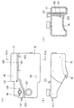
図1から図6を参照して、二輪車1は、車体フレーム3を有する。車体フレーム3は、ヘッドパイプ5と、ヘッドパイプ5から後方斜め下方に延びる縦断面I字型のフロントフレーム7と、フロントフレーム7の後端部に連結されかつ後方斜め上方に立ち上がる横断面H字型のリヤフレーム9と、シートレール27とを備えており、フロントフレーム7およびリヤフレーム9全体で側面視略V字状を成している。
1 to 6, the two-wheeled vehicle 1 has a
フロントフレーム7は、車軸方向に沿って延びかつ車幅方向に直交する板状部材7aと、板状部材7aのトップ側およびボトム側のそれぞれに車幅方向に沿って延びるフランジ部7b1および7b2と、板状部材7aの両表面に対して突設される補強リブ7cとを備えている。補強リブ7cは、フランジ部7b1および7b2とともに板状部材7aの両表面を区画して、後述する燃料電池システム70の構成部品の収納壁を構成する。
The front frame 7 includes a plate-
一方、リヤフレーム9は、車軸方向に対して斜め後方に延びかつフロントフレーム7のフランジ部7b1の上面に対向する板状部材9aと、板状部材9aの左右両側部において車軸方向に沿って延びるフランジ部9b1および9b2とを備えている。
リヤフレーム9の板状部材9aには、後述する水溶液タンク77に対する通気・冷却用の複数の通気孔9cが形成されている。On the other hand, the
The plate-
ヘッドパイプ5内には、車体方向変更用の図示しないステアリング軸が回動自在に挿通されている。このステアリング軸の上端には、ハンドル11aが固定されたハンドル支持部11が取り付けられており、ハンドル11aの両端にはグリップ13が取り付けられている。右側のグリップ13は回動可能なスロットルグリップを構成している。
A steering shaft (not shown) for changing the vehicle body direction is rotatably inserted into the
ヘッドパイプ5の下端から下方に向けて、左右一対のフロントフォーク15が取り付けられており、フロントフォーク15それぞれの下端には、前輪17が前車軸19を介して取り付けられている。前輪17は、フロントフォーク15により緩衝懸架された状態で前車軸19により回転自在に軸支されている。
A pair of left and right
ハンドル支持部11のハンドル11aの前方には、表示操作部(以下、メータと略記する)21が配置されている。メータ21は、運転者に対する走行状態等の各種情報提供用のたとえば液晶ディスプレイ等で構成された表示部、および運転者からの各種情報入力用の入力部等が一体化されたものである。ハンドル支持部11におけるメータ21の下方には、ヘッドランプ23が固定されており、ヘッドランプ23の左右両側方には、フラッシャランプ25がそれぞれ設けられている。
A display operation unit (hereinafter abbreviated as a meter) 21 is disposed in front of the
一方、リヤフレーム9の後方側端部には、パイプ部材から成る略U字状のシートレール27が取り付けられている。
シートレール27は、略C字状に屈曲する屈曲パイプ31と、屈曲パイプ31の両端からそれぞれ延在する左右一対のシート支持パイプ33a,33bと、シート支持パイプ33a,33bから分岐して後方斜め下方に延在する分岐パイプ34a,34bとを備えている。On the other hand, a substantially
The
シートレール27のシート支持パイプ33a,33bの中間の互いに対向する部位はリヤフレーム9のフランジ部9b1および9b2の上端部にたとえば溶接により固設されている。また、分岐パイプ34a,34bの後方側端部も、リヤフレーム9の板状部材9aにたとえば溶接により固定されている。シートレール27は、略車軸方向に沿って水平になるように配設されている。
The portions of the
シートレール27の屈曲パイプ31には、シートステー35が突設されており、シートレール27における屈曲パイプ31およびシート支持パイプ33a,33bのフレーム取り付け部位近傍までを覆うように、運転者が着座するシート37が設けられている。シート37は、シートステー35を介してシートレール27に対して離接する方向に沿って揺動自在(開閉自在)に支持されている。
A
シートレール27のシート支持パイプ33a,33bにおけるシートレール溶接部位の前方側の互いに対向する部位には、係合用ブラケット39が架設されており、閉状態のシート37を係合して固定可能になっている。
シートレール27のシート支持パイプ33a,33bの後方側端部には、取り付けブラケット41が固設されており、取り付けブラケット41を介してテールランプ43および左右一対のフラッシュランプ44がそれぞれ取り付けられている。
A mounting
一方、リヤフレーム9の下端部には、リヤアーム45がピボット軸47を介して揺動自在に支持されており、リヤアーム45の後端部45aには駆動輪である後輪49が回転自在に軸支されている。リヤアーム45および後輪49は、リヤクッション51によってリヤフレーム9に対して緩衝懸架されている。
On the other hand, a
フロントフレーム7の後端側のボトム部には、左右一対のフットステップ53(図1および図2には一方のみ図示)がそれぞれ配設されている。左側のフットステップ53の後方側には、サイドスタンド55が回動可能にリヤアーム45に支持されており、サイドスタンド55は、リターンスプリング57によって閉じ側に付勢されている。
A pair of left and right foot steps 53 (only one is shown in FIGS. 1 and 2) are disposed on the bottom portion on the rear end side of the front frame 7, respectively. On the rear side of the
リヤアーム45の後端部45aより内側には、後輪49に連結されかつ後輪49を回転駆動させるためのたとえばアキシャルギャップ型の電動モータ61と、電動モータ61に電気的に接続されており、電動モータ61の回転駆動を制御するためのコントローラ63を含む駆動ユニット65とがそれぞれ配設されている。
Inside the
そして、この実施形態に係る二輪車1には、車体フレーム3(フロントフレーム7、リヤフレーム9およびシートレール27)に沿って配置される燃料電池システム70と、フロントフレーム7の板状部材7aの両表面にリブ7cにより画成された収納スペースに収納配置される二次電池71とが搭載されている。燃料電池システム70は、電動モータ61駆動用および補機類用等電気構成部品駆動用の電気エネルギーを生成する。二次電池71は、燃料電池システム70により生成された電気エネルギーを蓄積し、コントローラ63の指令に応じて蓄積した電気エネルギーを対応する電気構成部品に供給する。たとえば、二次電池71は、駆動ユニット65に電気エネルギーを供給し、それによって電動モータ61を回転させて後輪49を回転駆動し二輪車1を走行させる。
In the two-wheeled vehicle 1 according to this embodiment, both the
以下、燃料電池システム70について説明する。
この実施形態に係る二輪車1に搭載された燃料電池システム70は、メタノール(メタノール水溶液)を改質せずにダイレクトに発電に利用するダイレクトメタノール型燃料電池システムである。Hereinafter, the
The
燃料電池システム70は、リヤフレーム9の板状部材9aの前方側の面に沿って取り付けられ、シート37の下方側かつ二輪車1の略中央部に配置される燃料電池セルスタック(以下、単にセルスタックという)73を備えている。
The
セルスタック73は、メタノールに基づく水素と酸素との電気化学反応により電気エネルギーを生成することができる単電池セルを複数個積層(スタック)して構成されている。セルスタック73を構成する各単電池セルは、固体分子膜等から構成された電解質(電解質膜)と、電解質を挟んで互いに対向する燃料極(アノード)および空気極(カソード)とを備えている。なお、図2〜図6では、各単電池セルの図示は省略されている。
The
セルスタック73の後方斜め上方かつシート37の後方側(後輪49の上方側)には、燃料タンク75と水溶液タンク77とが左右に並置されている。燃料タンク75と水溶液タンク77とは、それぞれ、前方側に向かって延びるように設けられ、前方側端部がシート37の下方に至る。燃料タンク75および水溶液タンク77は、たとえばシートレール27の取り付けブラケット41等を介して支持フレーム33aおよび33bの下方側に取り付けられている。燃料タンク75および水溶液タンク77は、たとえばPE(ポリエチレン)ブロー成型によって得られる。燃料タンク75および水溶液タンク77は、それぞれ樹脂製である。
A
燃料タンク75は、セルスタック73の上記電気化学反応の燃料となる高濃度(たとえば、約50%)のメタノール燃料(高濃度メタノール水溶液)を収容している。
The
また、水溶液タンク77は、燃料タンク75に収容されたメタノール燃料をセルスタック73の電気化学反応に適した濃度(たとえば、約3%)に希釈したメタノール水溶液を収容している。
The
燃料タンク75および水溶液タンク77は、それぞれの高さ(たとえば、それぞれのタンク底面の高さ)が略一致するように左右に並置され、一体化された状態でシートレール27に取り付けられている。ここでいう燃料タンク75と水溶液タンク77との高さが略一致とは、水溶液タンク77内の燃料電池システム70の運転時におけるメタノール水溶液の液面高さに対して燃料タンク75内のメタノール燃料の液面高さが±10cm以内に収まるように両タンクがレイアウトされることをいう。好ましくは両タンクの液面高さの差は±5cm以内に設定される。一体化される燃料タンク75と水溶液タンク77との横幅合計寸法は、シート37の横幅寸法以下である(図2参照)。
The
図5に示すように、セルスタック73の後方側にはセルスタック73と並ぶように熱交換器79が設けられている。熱交換器79は、板状部材9aの後方側の面にセルスタック73に沿うように取り付けられ、シート37の下方側に位置する。水溶液タンク77からのメタノール水溶液を冷却する熱交換器79の熱交換パイプP1の入口部は、水溶液タンク77のたとえば底面側のメタノール水溶液出口部80に接続パイプ(接続配管)81によって接続されている。
As shown in FIG. 5, a
また、燃料タンク75の下方の高濃度メタノール水溶液出口82(図10参照)には接続パイプ83が接続されている。接続パイプ83は、燃料タンク75および水溶液タンク77の下方側に配置される燃料ポンプ85の入口(流入)側端部に接続されている。燃料タンク75からのメタノール燃料を水溶液タンク77に圧送して供給する燃料ポンプ85は、たとえば熱交換器79に一体的に取り付けられている。燃料ポンプ85の出口(吐出)側端部と水溶液タンク77の前方側端部に設けられるメタノール燃料入口部89とは接続パイプ91によって接続されている。
Further, a
さらに、熱交換器79の熱交換パイプP1の出口部79aと水溶液ポンプ95とは、接続パイプ93を介して接続されている。水溶液ポンプ95は、セルスタック73の下方に配置され、フロントフレーム7の板状部材7aの左側面側にリブ7c等で区画形成された所定の収納スペースに収納配置されている。
Furthermore, the
水溶液ポンプ95の吐出側端部は、接続パイプ97を介してフィルタ99に接続されている。フィルタ99は、フロントフレーム7の板状部材7aの右側面側にリブ7c等で区画形成された所定の収納スペースに収納配置され、接続パイプ97を流れるメタノール水溶液内の不純物を取り除く。
The discharge side end of the
フィルタ99の出力側は、接続パイプ101に接続されており、接続パイプ101は、セルスタック73のたとえばボトム側の燃料(メタノール水溶液)供給用の燃料入口I1に接続されている。
The output side of the
接続パイプ101におけるフィルタ99とセルスタック73との間の所定位置には、接続パイプ101から分岐した分岐パイプ(分岐配管)103が設けられている。分岐パイプ103には、接続パイプ101を流れるメタノール水溶液の濃度をたとえば超音波等を用いて検出し、検出した濃度を示す濃度信号(図11中C8として示す)をコントローラ63に送信するための濃度検出部としての濃度センサ105が設けられている(図11参照)。
A branch pipe (branch pipe) 103 branched from the
また、シートレール27の屈曲パイプ31に突設された支持ブラケット107によって、シートレール27のシート支持パイプ33a,33b間および分岐パイプ34a,34b間に介挿されるようにエアポンプ109が支持されている。エアポンプ109は、セルスタック73の上方側、かつ燃料タンク75および水溶液タンク77の前方側に配置されている。
The
エアポンプ109の後方側であってシート支持パイプ33a,33bおよび分岐パイプ34a、34b間に介挿されるように、供給エア脈動除去用のチャンバ室111が配設されている。チャンバ室111は、エアポンプ109の吐出側出力部に接続されている。チャンバ室111は接続パイプ113を介して、セルスタック73のたとえば上方側の空気入口I2に接続されている。この実施形態では、エアポンプ109と接続パイプ113を含んでエア供給部が構成されている。
A
セルスタック73には、燃料入口I1の対角となる位置に二酸化炭素(未反応メタノール成分、水蒸気を含む)出口I3が設けられている。二酸化炭素出口I3には、接続パイプ115を介して水溶液タンク77の前方側端部に設けられる二酸化炭素(未反応メタノール)入口部117が接続されている。
The
また、セルスタック73には、空気入口I2の対角となる位置に空気(水蒸気)を排気として排出するための空気(水蒸気)出口I4が設けられている。空気出口I4には、接続パイプ118を介して空気(水蒸気)を冷却するための排気冷却器(気液分離器)119の熱交換パイプP2の入口部が接続されている。排気冷却器119は、フロントフレーム7の後端部(湾曲部)に対して前方側斜め上方に位置するように、フロントフレーム7のフランジ部7b2の前方側表面に沿って取り付けられている。図2〜図4からわかるように、フロントフレーム7において前方側かつ略中央部に排気冷却器119を配置することによって、排気冷却器119が走行風を受けやすくなり、水蒸気の冷却を効率的に行うことができる。また、排気冷却器119は、熱交換器79よりも外部に放出する熱量が多い。外部に放出する熱量が多い排気冷却器119と燃料タンク75および水溶液タンク77とを離間するように配置することによって、メタノールの蒸発を防いでいる。
Further, the
さらに、排気冷却器119の熱交換パイプP2の出口部には、接続パイプ121を介して水タンク123が接続されている。水タンク123は、セルスタック73の下方かつフロントフレーム7の板状部材7aの左側面側の所定の収納スペースに収納配置されている。
Furthermore, a
水タンク123には、そのタンク本体123aに送り込まれた気体(排ガス)を排出するためのドレインパイプ(ドレイン配管)125がタンク本体123aの上部に取り付けられている。
In the
さらに、セルスタック73の下方かつフロントフレーム7の板状部材7aの左側面側には、水ポンプ127が収納配置されている。水ポンプ127は、タンク本体123aのボトム部に接続された接続パイプ128に接続されており、水ポンプ127の出力側は、接続パイプ129を介して水溶液タンク77の前方側端部に設けられる水入口部130(図10参照)に接続されている。この実施形態では、水ポンプ127と接続パイプ128,129とによって水供給部が構成されている。
Further, a
また、図7からよくわかるように、水溶液タンク77の上部には二酸化炭素出口部131が設けられている。二酸化炭素出口部131には接続パイプ133の一端部が接続されている。接続パイプ133は、セルスタック73の二酸化炭素出口I3から接続パイプ115および二酸化炭素入口部117を介して水溶液タンク77に入力された二酸化炭素を水タンク123に案内する。
As can be seen from FIG. 7, a
図8に示すように、接続パイプ133の他端部は、排気冷却器119と水タンク123とを連結するための接続パイプ121の途中に接続されている。
As shown in FIG. 8, the other end of the
すなわち、図9に示すように、接続パイプ133の下端部133aが、接続パイプ121の水タンク側端部121aの管軸方向に直交するように、水タンク側端部121aに接続されている。このとき、接続パイプ133における接続パイプ121内部側の先端部133bは、接続パイプ121内部に向かってテーパー状、すなわち、その管径が次第に狭くなるように形成され、接続パイプ121内部に突入している。
That is, as shown in FIG. 9, the
また、図8に示すように、接続パイプ121は、その管軸方向X1が、水タンク123内に接続されたドレインパイプ125の管軸方向X2に対して非平行となるように水タンク123内に接続されている。
Further, as shown in FIG. 8, the
図10(a)〜図10(c)に示すように、燃料タンク75は、平面視および一側面視でそれぞれ略矩形状を成す中空体であり、水溶液タンク77は、直方体形状から上記矩形状の燃料タンク75を切り欠いた際の残部に対応する形状を有する中空体である。
As shown in FIGS. 10A to 10C, the
燃料タンク75および水溶液タンク77それぞれの対向面は互いに略一致した形状を成しており、その一方の対向面(たとえば、水溶液タンク77対向面)から他方の対向面(たとえば、燃料タンク75の対向面)に向かって複数(たとえば3個)の嵌め込み凸部151がそれぞれ突出されている。
The opposing surfaces of the
このとき、燃料タンク75の対向面における嵌め込み凸部151に対向する位置には、それぞれ嵌め込み凸部151が嵌入可能な複数(3個)の嵌め込み凹部153が形成されている。嵌め込み凸部151の嵌め込み凹部153への嵌入によって、水溶液タンク77の対向面は燃料タンク75の対向面に対し所定距離(ギャップ)を隔てて近接配置される。
At this time, a plurality (three) of
そして、燃料タンク75および水溶液タンク77の対向面の間のギャップには断熱材155が充填され、燃料タンク75と水溶液タンク77とが一体化されている。このように、燃料タンク75と水溶液タンク77とを一体型タンクとして構成することによって、タンクをシートレール27に取り付ける際、個別に取り付ける場合と比べて、取り付け部品を減少できるとともに取り付け作業性を向上できる。
The gap between the opposing surfaces of the
図11に示すように、燃料タンク75には燃料データ検出部としての液面検出センサ171が取り付けられている。液面検出センサ171は、燃料タンク75内のメタノール燃料S1の液面の高さを検出し、センサ信号(図11中C1として示す)をコントローラ63に送信する。
As shown in FIG. 11, a liquid level detection sensor 171 as a fuel data detection unit is attached to the
水溶液タンク77には水溶液データ検出部としての液面検出センサ173が取り付けられている。液面検出センサ173は、水溶液タンク77内のメタノール水溶液S2の液面の高さを検出し、センサ信号(図11中C2として示す)をコントローラ63に送信する。
A liquid level detection sensor 173 as an aqueous solution data detection unit is attached to the
水タンク123には水データ検出部としての液面検出センサ175が取り付けられている。液面検出センサ175は、水タンク123内の水S3の液面の高さを検出し、センサ信号(図11中C3として示す)をコントローラ63に送信する。
A liquid
また、セルスタック73の燃料入口I1付近には温度センサ177が取り付けられている。温度センサ177は、燃料入口I1を介して供給されるメタノール水溶液の温度を検出してその温度検出信号(図11中C7として示す)をコントローラ63に送信する。
In addition, a temperature sensor 177 is attached in the vicinity of the fuel inlet I1 of the
燃料電池システム70のコントローラ63は、各種センサ105,171,173および175から送信されてきた検出信号に基づいて、必要に応じて燃料ポンプ85、水溶液ポンプ95、エアポンプ109および水ポンプ127のうちの少なくとも1つのポンプを駆動制御する。燃料ポンプ85、水溶液ポンプ95、エアポンプ109および水ポンプ127の駆動制御時には、それぞれ、コントローラ63から制御信号C5,C4,C9およびC6が送信される。
Based on the detection signals transmitted from the
図1に戻って、二輪車1のハンドル支持部11は、ハンドルカバー181によって覆われている。車体フレーム3におけるヘッドパイプ5の後方側のフロントフレーム7およびリヤフレーム9とシート37下部分(燃料電池システム70の各構成要素を含む)とは、シートカバー183によって覆われている。また、リヤフレーム9の後方側(燃料電池システム70における燃料タンク75および水溶液タンク77を含む)は、シートカバー183から後方側に延在するアッパーカバー185によって覆われている。ヘッドパイプ5の後側部分(燃料電池システム70の排気冷却器119を含む)は、運転者の足部を保護するレッグシールド187によって覆われている。
Returning to FIG. 1, the
つぎに、この実施形態の二輪車1に搭載される燃料電池システム70の全体動作について、発電時の動作を中心に説明する。
水溶液ポンプ95の駆動によって水溶液タンク77から供給された約3%の濃度のメタノール水溶液は、接続パイプ81を介して熱交換器79内に流入し、熱交換パイプP1を流れる間にファンF1によって、セルスタック73に適した温度(たとえば約40℃)に冷却(熱交換)される。Next, the overall operation of the
The methanol aqueous solution having a concentration of about 3% supplied from the
冷却されたメタノール水溶液は、接続パイプ93および97を介してフィルタ99に流入して不純物等が除去された後、接続パイプ101および燃料入口I1を介してセルスタック73のアノード側にダイレクトに供給される。
The cooled aqueous methanol solution flows into the
一方、エアポンプ109から供給された空気(エア)は、チャンバ室111を介して脈動が軽減された後、接続パイプ113およびセルスタック73の空気入口I2を介してカソード側に供給される。
On the other hand, the air (air) supplied from the
このとき、セルスタック73の各単電池セルにおけるアノード側では、供給されたメタノール水溶液におけるメタノールと水とが化学反応して二酸化炭素および水素イオンが生成される。生成された水素イオンは、電解質を介してカソード側に流入し、そのカソード側に供給されたエア中の酸素と電気化学反応して水および電気エネルギーが生成される。
生成された電気エネルギーは、二次電池71に送られて蓄積され、二輪車1の走行駆動等に利用される。At this time, on the anode side of each single battery cell of the
The generated electric energy is sent to and stored in the
一方、各単電池セルにおけるアノード側の電気化学反応によって生成された排出ガス{主に二酸化炭素(炭酸ガス)}は、上記電気化学反応により発生する熱によって温度上昇する(たとえば、約65℃〜70℃となる)。この排出ガス(二酸化炭素)には、アノード側において未反応であった上記高温のメタノール成分が含まれている。 On the other hand, the exhaust gas {mainly carbon dioxide (carbon dioxide)} generated by the electrochemical reaction on the anode side in each unit cell rises in temperature due to the heat generated by the electrochemical reaction (for example, about 65 ° C to 70 ° C). The exhaust gas (carbon dioxide) contains the high-temperature methanol component that has not reacted on the anode side.
この未反応メタノール成分を含む排出ガス(二酸化炭素)は、セルスタック73の二酸化炭素出口I3および接続パイプ115を介して水溶液タンク77に戻される。
水溶液タンク77に戻された未反応メタノール成分を含む排出ガス(二酸化炭素)は、水溶液タンク77の上部に位置する二酸化炭素出口部131を経由して水溶液タンク77から流出し、接続パイプ133を流れる。The exhaust gas (carbon dioxide) containing the unreacted methanol component is returned to the
The exhaust gas (carbon dioxide) containing the unreacted methanol component returned to the
接続パイプ133は、リヤフレーム9の上方に位置する水溶液タンク77からフロントフレーム7内に位置する接続パイプ121まで長い距離に亘って延在している。そのため、接続パイプ133を流れる未反応メタノール成分を含む排出ガス(二酸化炭素)は、たとえば上記約40℃程度に十分冷却された状態で接続パイプ121の水タンク側端部121a、すなわち、排気冷却器119および水タンク123を接続する接続パイプに向かって流れる。
The
一方、カソード側で生成された水蒸気は、空気(水蒸気)出口I4および接続パイプ118を介して排気冷却器119の熱交換パイプP2を流れ、その間にファンF2による冷却(温度低下)により気液分離される。
On the other hand, the water vapor generated on the cathode side flows through the heat exchange pipe P2 of the
このようにして分離された気体成分(水蒸気)は、高速(たとえば、毎分約140リットル)で接続パイプ121を流れ(図9中矢印Y1参照)、水タンク連通側端部121aを介して水タンク123内に流入する。
The gas component (water vapor) thus separated flows through the
一方、上述したように、接続パイプ121の水タンク側端部121aには、接続パイプ133を介して未反応メタノール成分を含む排出ガス(二酸化炭素)が送られてくる。
On the other hand, as described above, exhaust gas (carbon dioxide) containing unreacted methanol components is sent to the water tank
このとき、水溶液タンク77の内圧が水タンク123の内圧より低いと仮定すると、未反応メタノール成分を含む排出ガス(二酸化炭素)を水タンク123へ戻すことができず、未反応メタノール成分を回収することができない。
At this time, assuming that the internal pressure of the
水溶液タンク77の内圧を水タンク123の内圧よりも高くしておくことが考えられるが、その場合、水溶液タンク77内に溶け込む二酸化炭素量を増大させ、さらに水溶液タンク77へメタノール燃料を送出する燃料ポンプ85および水を戻す水ポンプ127の負荷を増大させてしまい、エネルギー効率を低下させるおそれがある。
Although it is conceivable that the internal pressure of the
この実施形態では、図8および9に示すように、接続パイプ133の先端部133bが接続パイプ121内部に突入しているため、接続パイプ下端部133aの出口部分121bにおける接続パイプ121の管径が実質的に狭くなる。その結果、接続パイプ121を流れる気体成分は、出口部分121bにおいて流速が上昇し、ベルヌーイの定理によって出口部分121bの圧力が周囲よりも減少する(出口部分121bに負圧が発生する)。その結果、接続パイプ下端部133aに流れ込んだ二酸化炭素は、霧吹きの原理により接続パイプ121内部に吸い出され、接続パイプ121を高速に流れる気体成分と共に水タンク123内に流入する。
In this embodiment, as shown in FIGS. 8 and 9, since the
このとき、この実施形態では、水タンク123内において、図8に示すように、接続パイプ121の管軸方向X1が、水タンク123内に接続されたドレインパイプ125の管軸方向X2に対して非平行となっている。そのため、水タンク123内に流入した大半の気体成分は、図中矢印Zで示すように、水タンク123内部をそのタンク内壁に衝突しながら循環し、水滴成分、すなわち、未反応メタノールの水溶液成分は水タンク123内部に効率良く滴下して次第にドレインパイプ125から排出される。
At this time, in this embodiment, in the
その結果、この実施形態では、セルスタック73による電気化学反応により生成された二酸化炭素に含まれる未反応メタノール成分を、全体のエネルギー効率を低下させることなく、水タンク123において容易かつ高効率で回収することができる。
As a result, in this embodiment, the unreacted methanol component contained in the carbon dioxide generated by the electrochemical reaction by the
一方、燃料電池システム70の発電動作時において、コントローラ63は、濃度センサ105により検出されたメタノール水溶液の濃度を表す濃度信号C8、液面検出センサ171により検出された燃料タンク75内の液面S1の高さに関するセンサ信号C1、液面検出センサ173により検出された水溶液タンク77内の液面S2の高さに関するセンサ信号C2、液面検出センサ175により検出された水タンク123内の液面S3の高さに関するセンサ信号C3、および温度センサ177により検出されたセルスタック73へダイレクトに供給されるメタノール水溶液の温度検出信号C7等に基づいて、燃料ポンプ85、水溶液ポンプ95、エアポンプ109および水ポンプ127の駆動制御をそれぞれ行う。
On the other hand, during the power generation operation of the
この実施形態によれば、シート37の後方側に燃料タンク75と水溶液タンク77とを並置することによって、燃料タンク75および水溶液タンク77の周囲に十分な作業空間を確保できる。したがって、燃料タンク75および水溶液タンク77の取り付け作業や取り外し作業が容易になり、メンテナンス性を向上できる。
According to this embodiment, a sufficient working space can be secured around the
また、燃料電池システム70において複数の構成要素に接続されるセルスタック73をシート37の下方側つまり二輪車1の略中央部に配置することによって、燃料電池システム70の各構成要素を簡単にレイアウトでき、各構成要素間の配管を簡易に短くできる。さらに、重量が嵩むセルスタック73を二輪車1の略中央部に配置することによって、二輪車1の重量バランスが良好になり、安定性を向上できる。
In addition, by disposing the
また、燃料タンク75および水溶液タンク77が前方側に向かって延びるように設けられていることによって、燃料電池システム70の各構成要素間の配管をより簡易にできる。特に、複数の接続パイプが接続される水溶液タンク77が前方側つまり二輪車1の中央部に向けて延ばされていることによって、水溶液タンク77と水溶液タンク77に接続される燃料電池システム70の各構成要素とが近づき、配管を簡易にできる。
In addition, since the
また、シート37の下方側かつセルスタック73の後方側に熱交換器79を配置することによって、水溶液タンク77、熱交換器79、セルスタック73が後方から前方にかけて順に配置されている。したがって、メタノール水溶液の流路を迂回させることがなく、水溶液タンク77からセルスタック73までの配管を簡易にできるとともに水溶液タンク77からのメタノール水溶液を熱交換器79を介してセルスタック73に速やかに供給できる。
Further, by disposing the
また、一体化される燃料タンク75と水溶液タンク77との横幅合計寸法がシート37の横幅寸法以下であるので、燃料タンク75と水溶液タンク77とをシート37に対して左右に膨らむことがないようにシート37の後方側に配置される。したがって、二輪車1が横方向に倒れても、燃料タンク75および水溶液タンク77を破損させるおそれが少なくなる。また、重量を横方向に分散させることがないので、旋回等のために二輪車1を横方向に傾斜させる際の走行安定性を向上できる。
Further, since the total width of the
また、燃料タンク75と水溶液タンク77とをそれぞれのタンク底面の高さが略一致するように並置することによって、燃料タンク75に収容されたメタノール燃料の液面高さと水溶液タンク77に収容されたメタノール水溶液の液面高さとを略一致させることができる。したがって、燃料タンク75および水溶液タンク77の下方側に配置される燃料ポンプ85を用いて燃料タンク75から水溶液タンク77へメタノール燃料を供給する際に、各タンクの液面の差に起因する燃料ポンプ85の入口と出口との間の圧力差を小さくできる。その結果、比較的小さな吐出性能を有する燃料ポンプ85を用いることができ、また、燃料ポンプ85によるメタノール燃料の供給精度を向上できる。したがって、燃料ポンプ85を容易に設計・製作することができ、二輪車1に搭載する燃料電池システム70全体の設計・製作コストを低減することができる。さらに、燃料ポンプ85を燃料タンク75の下方に配置することによって、燃料タンク75から燃料ポンプ85へメタノール燃料を重力によって容易に供給できる。
Further, the
この実施形態では、シート37の後方側に燃料タンク75と水溶液タンク77とを並置する場合について説明したが、シート37の後方側かつ空間を確保できる位置であれば、任意の位置に燃料タンク75と水溶液タンク77とを並置できる。たとえば、シートの後方斜め上方に燃料タンクと水溶液タンクとを並置するようにしてもよい。
In this embodiment, the case where the
また、この実施形態では、燃料タンク75と水溶液タンク77とを左右に並置する場合について説明したが、両タンクの配置態様および形状は任意に設定できる。たとえば、燃料タンクと水溶液タンクとを前後に並置してもよく、この場合、配管の容易さを考慮して燃料タンクの前方側に水溶液タンクを並置することが好ましい。
Moreover, although this embodiment demonstrated the case where the
また、この実施形態では、燃料としてメタノール燃料、燃料水溶液としてメタノール水溶液を用いたが、これに限定されず、燃料としてエタノール等のアルコール系の燃料、燃料水溶液としてエタノール等のアルコール系の水溶液を用いてもよい。 In this embodiment, methanol fuel is used as the fuel, and methanol aqueous solution is used as the aqueous fuel solution. However, the present invention is not limited to this, and an alcohol-based fuel such as ethanol is used as the fuel, and an alcohol-based aqueous solution such as ethanol is used as the fuel aqueous solution. May be.
さらに、この実施形態では、燃料電池システムを搭載した鞍乗型車両として二輪車について説明したが、これに限定されず、この発明は、三輪車、四輪車等の任意の鞍乗型車両に用いることができる。 Furthermore, in this embodiment, a two-wheeled vehicle has been described as a saddle-type vehicle equipped with a fuel cell system. However, the present invention is not limited to this, and the present invention is used for any straddle-type vehicle such as a tricycle or a four-wheel vehicle. Can do.
この発明が詳細に説明され図示されたが、それは単なる図解および一例として用いたものであり、限定であると解されるべきではないことは明らかであり、この発明の精神および範囲は添付された請求の範囲の文言のみによって限定される。 Although the present invention has been described and illustrated in detail, it is clear that it has been used merely as an illustration and example and should not be construed as limiting, and the spirit and scope of the present invention are attached Limited only by the language of the claims.
Claims (6)
燃料水溶液を収容する水溶液タンク、
前記水溶液タンクに供給すべき燃料を収容する燃料タンク、および
前記水溶液タンクからの前記燃料水溶液が供給され電気化学反応によって電気エネルギーを生成する燃料電池セルスタックを備え、
前記燃料タンクと前記水溶液タンクとが前記シートの後方側に並置される、鞍乗型車両。The seat on which the driver sits,
An aqueous solution tank containing an aqueous fuel solution,
A fuel tank that contains fuel to be supplied to the aqueous solution tank, and a fuel battery cell stack that is supplied with the aqueous fuel solution from the aqueous solution tank and generates electrical energy by an electrochemical reaction,
A straddle-type vehicle in which the fuel tank and the aqueous solution tank are juxtaposed on the rear side of the seat.
前記燃料タンクおよび前記水溶液タンクの下方側に配置され、かつ前記燃料タンクからの前記燃料を圧送して前記水溶液タンクに供給するために前記燃料タンクと前記水溶液タンクとに接続される燃料ポンプをさらに含む、請求項1に記載の鞍乗型車両。The fuel tank and the aqueous solution tank are juxtaposed so that their heights substantially coincide with each other,
A fuel pump disposed below the fuel tank and the aqueous solution tank and connected to the fuel tank and the aqueous solution tank to pump the fuel from the fuel tank and supply it to the aqueous solution tank; The straddle-type vehicle according to claim 1, further comprising:
Applications Claiming Priority (3)
| Application Number | Priority Date | Filing Date | Title |
|---|---|---|---|
| JP2003365205 | 2003-10-24 | ||
| JP2003365205 | 2003-10-24 | ||
| PCT/JP2004/015421 WO2005041338A1 (en) | 2003-10-24 | 2004-10-19 | Saddle riding-type vehicle |
Publications (1)
| Publication Number | Publication Date |
|---|---|
| JPWO2005041338A1 true JPWO2005041338A1 (en) | 2007-11-29 |
Family
ID=34510156
Family Applications (1)
| Application Number | Title | Priority Date | Filing Date |
|---|---|---|---|
| JP2005514949A Pending JPWO2005041338A1 (en) | 2003-10-24 | 2004-10-19 | Saddle riding vehicle |
Country Status (6)
| Country | Link |
|---|---|
| US (1) | US20080166607A1 (en) |
| EP (2) | EP1691436B1 (en) |
| JP (1) | JPWO2005041338A1 (en) |
| AT (1) | ATE524847T1 (en) |
| TW (2) | TW200524763A (en) |
| WO (2) | WO2005041338A1 (en) |
Families Citing this family (23)
| Publication number | Priority date | Publication date | Assignee | Title |
|---|---|---|---|---|
| JP4362343B2 (en) * | 2003-10-06 | 2009-11-11 | ヤマハ発動機株式会社 | Vehicle with fuel cell |
| JP4709518B2 (en) | 2004-09-29 | 2011-06-22 | 株式会社東芝 | Proton conducting membrane and fuel cell |
| JP2006236743A (en) * | 2005-02-24 | 2006-09-07 | Toshiba Corp | Fuel cell |
| JP4547297B2 (en) * | 2005-05-09 | 2010-09-22 | 本田技研工業株式会社 | Motorcycle |
| DE602006002154D1 (en) | 2005-04-04 | 2008-09-25 | Honda Motor Co Ltd | Motorcycle with fuel cell |
| JP2007042541A (en) * | 2005-08-05 | 2007-02-15 | Yamaha Motor Co Ltd | Fuel cell system and water replenishing method in it |
| US20070072022A1 (en) * | 2005-09-29 | 2007-03-29 | Yamaha Hatsudoki Kabushiki Kaisha | Fuel cell system and transport equipment including the same |
| JP4641241B2 (en) * | 2005-09-30 | 2011-03-02 | 本田技研工業株式会社 | Fuel cell vehicle cooling system |
| JP4648149B2 (en) * | 2005-09-30 | 2011-03-09 | 本田技研工業株式会社 | Fuel cell motorcycle |
| JP4804969B2 (en) * | 2006-03-16 | 2011-11-02 | 本田技研工業株式会社 | Front structure of a fuel cell vehicle |
| EP2104958A2 (en) | 2006-11-07 | 2009-09-30 | Polyfuel, Inc. | Passive recovery of liquid water produced by fuel cells |
| JP5252887B2 (en) * | 2006-11-16 | 2013-07-31 | ヤマハ発動機株式会社 | Fuel cell system and control method thereof |
| JP4968783B2 (en) * | 2007-03-30 | 2012-07-04 | 本田技研工業株式会社 | Saddle type fuel cell vehicle |
| JP2008310996A (en) * | 2007-06-12 | 2008-12-25 | Toshiba Corp | Fuel cell system and its control method |
| KR100982324B1 (en) | 2008-01-24 | 2010-09-15 | 삼성에스디아이 주식회사 | Fuel Cell System |
| JP4444355B2 (en) | 2008-09-03 | 2010-03-31 | 株式会社東芝 | Fuel cell |
| JP5382325B2 (en) * | 2009-04-13 | 2014-01-08 | スズキ株式会社 | A small vehicle equipped with a fuel cell |
| JP5417992B2 (en) * | 2009-05-27 | 2014-02-19 | スズキ株式会社 | Fuel cell vehicle |
| JP5831597B1 (en) * | 2014-06-06 | 2015-12-09 | トヨタ自動車株式会社 | Electric vehicle |
| JP2017081326A (en) * | 2015-10-27 | 2017-05-18 | スズキ株式会社 | Piping joint arrangement structure of fuel battery two-wheel vehicle |
| CN105599842A (en) * | 2015-12-31 | 2016-05-25 | 天津美格工业设计有限公司 | Two-wheeled vehicle |
| CN109131661B (en) * | 2018-07-28 | 2023-08-29 | 重庆隆鑫机车有限公司 | Motorcycle instrument mounting structure and motorcycle thereof |
| CN114883610A (en) * | 2022-05-23 | 2022-08-09 | 安徽青木子德慧能源发展有限公司 | Control system of skid-mounted distributed fuel cell power generation system |
Family Cites Families (18)
| Publication number | Priority date | Publication date | Assignee | Title |
|---|---|---|---|---|
| US4629664A (en) * | 1984-10-31 | 1986-12-16 | Hitachi, Ltd. | Liquid fuel cell |
| US5773162A (en) * | 1993-10-12 | 1998-06-30 | California Institute Of Technology | Direct methanol feed fuel cell and system |
| JP4081207B2 (en) * | 1999-06-22 | 2008-04-23 | 本田技研工業株式会社 | Fuel cell system |
| JP2001155749A (en) * | 1999-11-30 | 2001-06-08 | Yamaha Motor Co Ltd | Vehicle provided with fuel cell drive system |
| JP2001163063A (en) * | 1999-12-06 | 2001-06-19 | Yamaha Motor Co Ltd | Vehicle with fuel cell driving system |
| JP2001351653A (en) * | 2000-06-02 | 2001-12-21 | Yamaha Motor Co Ltd | Fuel cell system |
| JP2001354179A (en) * | 2000-06-14 | 2001-12-25 | Honda Motor Co Ltd | Fuel cell-mounted motorcycle |
| DE10035756A1 (en) * | 2000-07-22 | 2002-01-31 | Daimler Chrysler Ag | Fuel cell system has device for dosing and feeding combustion medium to cathode chamber depending on determined temperature |
| JP3893898B2 (en) * | 2001-04-20 | 2007-03-14 | 株式会社ジーエス・ユアサコーポレーション | FUEL CELL SYSTEM, FUEL CELL SYSTEM OPERATION CONTROL METHOD, AND PROGRAM FOR CONTROLLING FUEL CELL SYSTEM OPERATION |
| KR100912157B1 (en) * | 2001-07-18 | 2009-08-14 | 텔-아비브 유니버시티 퓨처 테크놀로지 디벨롭먼트 엘.피. | Cathode, membrane electrode assemblymea, fuel cell arrangement, hybrid power source, liquid level detector, cellular phone, and fuel cell assembly |
| EP1280218A1 (en) * | 2001-07-27 | 2003-01-29 | Abb Research Ltd. | Method for adjusting the methanol concentration in direct methanol fuel cells |
| US6696195B2 (en) * | 2001-08-09 | 2004-02-24 | Motorola, Inc. | Direct methanol fuel cell including a water recovery and recirculation system and method of fabrication |
| JP3702827B2 (en) * | 2001-10-02 | 2005-10-05 | 日産自動車株式会社 | Fuel cell system |
| JP2003132924A (en) * | 2001-10-30 | 2003-05-09 | Yuasa Corp | Fuel cell system directly feeding methanol |
| JP2003208910A (en) * | 2002-01-11 | 2003-07-25 | Yuasa Corp | Liquid-fuel direct supply type fuel cell system |
| JP3748417B2 (en) * | 2002-03-29 | 2006-02-22 | 株式会社東芝 | Direct liquid fuel fuel cell power generator and control method thereof |
| US20030196913A1 (en) * | 2002-04-19 | 2003-10-23 | Tuyu Xie | Method of measuring methanol concentration in an arqueous solution |
| DE102007062241A1 (en) * | 2006-12-27 | 2008-07-24 | Yamaha Hatsudoki K.K., Iwata | The fuel cell system |
-
2004
- 2004-10-19 AT AT04792590T patent/ATE524847T1/en not_active IP Right Cessation
- 2004-10-19 WO PCT/JP2004/015421 patent/WO2005041338A1/en active Application Filing
- 2004-10-19 EP EP04792590A patent/EP1691436B1/en not_active Not-in-force
- 2004-10-19 JP JP2005514949A patent/JPWO2005041338A1/en active Pending
- 2004-10-22 TW TW093132092A patent/TW200524763A/en not_active IP Right Cessation
- 2004-10-25 EP EP04793288A patent/EP1625634A2/en not_active Withdrawn
- 2004-10-25 WO PCT/JP2004/016187 patent/WO2005050769A2/en active Application Filing
- 2004-10-25 US US10/558,772 patent/US20080166607A1/en not_active Abandoned
- 2004-10-26 TW TW093132417A patent/TW200520294A/en unknown
Also Published As
| Publication number | Publication date |
|---|---|
| US20080166607A1 (en) | 2008-07-10 |
| TW200520294A (en) | 2005-06-16 |
| EP1691436B1 (en) | 2011-09-14 |
| ATE524847T1 (en) | 2011-09-15 |
| WO2005050769A2 (en) | 2005-06-02 |
| EP1691436A1 (en) | 2006-08-16 |
| TW200524763A (en) | 2005-08-01 |
| WO2005050769A3 (en) | 2005-07-14 |
| EP1691436A4 (en) | 2010-05-26 |
| TWI324568B (en) | 2010-05-11 |
| WO2005041338A1 (en) | 2005-05-06 |
| EP1625634A2 (en) | 2006-02-15 |
Similar Documents
| Publication | Publication Date | Title |
|---|---|---|
| JPWO2005041338A1 (en) | Saddle riding vehicle | |
| JP2010247574A (en) | Small vehicle mounted with fuel cell | |
| JP4606811B2 (en) | Control unit cooling structure in electric vehicle | |
| JP5055080B2 (en) | vehicle | |
| JP5001047B2 (en) | Motorcycle battery arrangement structure | |
| JP2008074200A (en) | Compact electric vehicle equipped with fuel cell | |
| JP2007200874A (en) | Fuel cell system and its operation method | |
| JP4646117B2 (en) | Fuel cell system and transportation equipment using the same | |
| JP6331838B2 (en) | Fuel cell motorcycle | |
| JP4968783B2 (en) | Saddle type fuel cell vehicle | |
| JP2005150106A (en) | Fuel cell system and transport equipment using above | |
| JP2011025861A (en) | Cooling device for power unit | |
| JP4390439B2 (en) | Fuel cell system | |
| JP2006182229A (en) | Two-wheel vehicle | |
| JP4422579B2 (en) | Fuel cell vehicle | |
| JP2005125840A (en) | Saddle type vehicle with fuel cell mounted thereon | |
| EP1722433A1 (en) | Fuel cell system and method therefor of measuring fuel concentration in fuel aqueous solution | |
| JP2006324236A (en) | Fuel cell system and method of measuring fuel concentration of fuel water solution | |
| JP2009093809A (en) | Fuel cell system and transport equipment including it | |
| JP2006351518A (en) | Fuel cell system and its control method | |
| JP2005112094A (en) | Fuel cell mounted vehicle | |
| JP2007076525A (en) | Motorcycle | |
| JP2011255827A (en) | Fuel cell motorcycle | |
| JP4911946B2 (en) | Fuel cell system and fuel concentration detection method thereof. | |
| JP4872559B2 (en) | Small electric vehicle with fuel cell |
Legal Events
| Date | Code | Title | Description |
|---|---|---|---|
| A131 | Notification of reasons for refusal |
Free format text: JAPANESE INTERMEDIATE CODE: A131 Effective date: 20090106 |
|
| A02 | Decision of refusal |
Free format text: JAPANESE INTERMEDIATE CODE: A02 Effective date: 20090512 |