JP7706552B2 - heating device - Google Patents

heating device Download PDF

Info

Publication number
JP7706552B2
JP7706552B2 JP2023536689A JP2023536689A JP7706552B2 JP 7706552 B2 JP7706552 B2 JP 7706552B2 JP 2023536689 A JP2023536689 A JP 2023536689A JP 2023536689 A JP2023536689 A JP 2023536689A JP 7706552 B2 JP7706552 B2 JP 7706552B2
Authority
JP
Japan
Prior art keywords
electrode
metal plate
heating
plate
heating device
Prior art date
Legal status (The legal status is an assumption and is not a legal conclusion. Google has not performed a legal analysis and makes no representation as to the accuracy of the status listed.)
Active
Application number
JP2023536689A
Other languages
Japanese (ja)
Other versions
JPWO2023002861A5 (en
JPWO2023002861A1 (en
Inventor
浩幸 前田
Current Assignee (The listed assignees may be inaccurate. Google has not performed a legal analysis and makes no representation or warranty as to the accuracy of the list.)
Kyocera Corp
Original Assignee
Kyocera Corp
Priority date (The priority date is an assumption and is not a legal conclusion. Google has not performed a legal analysis and makes no representation as to the accuracy of the date listed.)
Filing date
Publication date
Application filed by Kyocera Corp filed Critical Kyocera Corp
Publication of JPWO2023002861A1 publication Critical patent/JPWO2023002861A1/ja
Publication of JPWO2023002861A5 publication Critical patent/JPWO2023002861A5/ja
Application granted granted Critical
Publication of JP7706552B2 publication Critical patent/JP7706552B2/en
Active legal-status Critical Current
Anticipated expiration legal-status Critical

Links

Images

Classifications

    • HELECTRICITY
    • H05ELECTRIC TECHNIQUES NOT OTHERWISE PROVIDED FOR
    • H05BELECTRIC HEATING; ELECTRIC LIGHT SOURCES NOT OTHERWISE PROVIDED FOR; CIRCUIT ARRANGEMENTS FOR ELECTRIC LIGHT SOURCES, IN GENERAL
    • H05B3/00Ohmic-resistance heating
    • H05B3/02Details
    • H05B3/03Electrodes
    • HELECTRICITY
    • H05ELECTRIC TECHNIQUES NOT OTHERWISE PROVIDED FOR
    • H05BELECTRIC HEATING; ELECTRIC LIGHT SOURCES NOT OTHERWISE PROVIDED FOR; CIRCUIT ARRANGEMENTS FOR ELECTRIC LIGHT SOURCES, IN GENERAL
    • H05B3/00Ohmic-resistance heating
    • H05B3/20Heating elements having extended surface area substantially in a two-dimensional plane, e.g. plate-heater

Landscapes

  • Resistance Heating (AREA)

Description

開示の実施形態は、加熱装置に関する。 The disclosed embodiments relate to a heating device.

従来、複数のカートリッジヒータが側面から挿入された加熱板を有し、かかる加熱板に対象物を接触させることによって対象物を加熱する加熱装置が知られている。特許文献1には、加熱板からの熱の散逸を防ぐために、加熱板の裏面(加熱面の反対側に位置する面)の略全面に断熱材が設けられた加熱装置が知られている(特許文献1参照)。Conventionally, a heating device has been known that has a heating plate into which multiple cartridge heaters are inserted from the side, and heats an object by bringing the object into contact with the heating plate. Patent Document 1 discloses a heating device in which a heat insulating material is provided over almost the entire back surface of the heating plate (the surface opposite the heating surface) to prevent heat from dissipating from the heating plate (see Patent Document 1).

特開2021-003885号公報JP 2021-003885 A

実施形態の一態様による加熱装置は、加熱プレートと、複数のヒータと、集合電極と、を備える。加熱プレートは、加熱面と、該加熱面の反対側に位置する複数の凹部と、を有する。複数のヒータは、複数の凹部にそれぞれ位置しているとともに、それぞれリード電極に接続される。集合電極は、2以上のリード電極に接続される。A heating device according to one aspect of the embodiment includes a heating plate, a plurality of heaters, and a collection electrode. The heating plate has a heating surface and a plurality of recesses located on the opposite side of the heating surface. The plurality of heaters are located in the plurality of recesses, respectively, and are each connected to a lead electrode. The collection electrode is connected to two or more lead electrodes.

図1は、実施形態に係る加熱装置をY軸負方向から見た側面図である。FIG. 1 is a side view of a heating device according to an embodiment, as viewed from the negative direction of the Y axis. 図2は、実施形態に係るヒータの断面図である。FIG. 2 is a cross-sectional view of the heater according to the embodiment. 図3は、実施形態に係る加熱装置をZ軸正方向から見た平面図である。FIG. 3 is a plan view of the heating device according to the embodiment, as viewed from the positive direction of the Z axis. 図4は、図3に示すIV-IV線における断面図である。FIG. 4 is a cross-sectional view taken along line IV-IV shown in FIG. 図5は、図3に示すV-V線における断面図である。FIG. 5 is a cross-sectional view taken along line VV shown in FIG. 図6は、実施形態に係る加熱装置をX軸負方向から見た側面図である。FIG. 6 is a side view of the heating device according to the embodiment, as viewed from the negative direction of the X-axis. 図7は、図6に示すVII-VII線矢視における断面図である。FIG. 7 is a cross-sectional view taken along line VII-VII of FIG. 図8は、実施形態に係る加熱装置をY軸正方向から見た側面図である。FIG. 8 is a side view of the heating device according to the embodiment, as viewed from the positive direction of the Y axis. 図9は、実施形態に係る複数の陰極側集合電極をZ軸負方向から見た平面図である。FIG. 9 is a plan view of a plurality of cathode side aggregate electrodes according to the embodiment, as viewed from the negative direction of the Z axis. 図10は、第1変形例に係る陽極側集合電極の断面図である。FIG. 10 is a cross-sectional view of an anode-side assembly electrode according to a first modified example. 図11は、第2変形例に係る陽極側集合電極の断面図である。FIG. 11 is a cross-sectional view of an anode-side assembly electrode according to a second modified example. 図12は、第3変形例に係る複数の陽極側集合電極をX軸負方向から見た側面図である。FIG. 12 is a side view of a plurality of anode side aggregate electrodes according to the third modified example, as viewed from the negative direction of the X-axis. 図13は、第4変形例に係る加熱装置をY軸負方向から見た側面図である。FIG. 13 is a side view of the heating device according to the fourth modified example, as viewed from the negative direction of the Y axis. 図14は、第5変形例に係る加熱装置をX軸負方向から見た側面図である。FIG. 14 is a side view of the heating device according to the fifth modified example, as viewed from the negative direction of the X-axis.

以下に、本開示による加熱装置を実施するための形態(以下、「実施形態」と記載する)について図面を参照しつつ詳細に説明する。なお、この実施形態により本開示による加熱装置が限定されるものではない。また、各実施形態は、処理内容を矛盾させない範囲で適宜組み合わせることが可能である。また、以下の各実施形態において同一の部位には同一の符号を付し、重複する説明は省略される。 Below, a form for implementing the heating device according to the present disclosure (hereinafter, referred to as "embodiment") will be described in detail with reference to the drawings. Note that the heating device according to the present disclosure is not limited to this embodiment. Furthermore, each embodiment can be appropriately combined as long as the processing content is not contradictory. Furthermore, the same parts in each of the following embodiments are given the same reference numerals, and duplicate explanations will be omitted.

また、以下に示す実施形態では、「一定」、「直交」、「垂直」あるいは「平行」といった表現が用いられる場合があるが、これらの表現は、厳密に「一定」、「直交」、「垂直」あるいは「平行」であることを要しない。すなわち、上記した各表現は、たとえば製造精度、設置精度などのずれを許容するものとする。In addition, in the embodiments described below, expressions such as "constant," "orthogonal," "vertical," and "parallel" may be used, but these expressions do not necessarily mean "constant," "orthogonal," "vertical," or "parallel" in the strict sense. In other words, each of the above expressions allows for deviations due to, for example, manufacturing precision, installation precision, and the like.

また、以下で参照する各図は、説明の便宜上の模式的なものである。したがって、細部は省略されることがあり、また、寸法比率は必ずしも現実のものとは一致していない。In addition, the figures referenced below are schematic for the convenience of explanation. Therefore, details may be omitted and the dimensional ratios do not necessarily correspond to the actual ones.

また、以下参照する各図面では、説明を分かりやすくするために、互いに直交するX軸方向、Y軸方向およびZ軸方向を規定し、Z軸正方向を鉛直上向き方向とする直交座標系を示す場合がある。 In addition, in order to make the explanation easier to understand, the drawings referenced below may show an orthogonal coordinate system that defines mutually perpendicular X-axis, Y-axis, and Z-axis directions and defines the positive Z-axis direction as the vertically upward direction.

カートリッジヒータは、長手方向に温度分布が生じる。このため、特許文献1に記載の技術のように断熱材を用いて熱の散逸を防ぐ構成では、断熱材の中央部付近における金属板の温度と外周部付近における金属板の温度とに差が生じやすく、金属板の温度を均一にすることが難しかった。 A cartridge heater has a temperature distribution in the longitudinal direction. For this reason, in a configuration in which heat insulation is used to prevent heat dissipation, as in the technology described in Patent Document 1, a difference in temperature between the metal plate near the center of the insulation and the metal plate near the periphery is likely to occur, making it difficult to make the temperature of the metal plate uniform.

また、複数のカートリッジヒータにおいて発生した熱が各カートリッジヒータのリード電極からバラバラに散逸することで、金属板の温度が不均一化するおそれがあった。 In addition, the heat generated in multiple cartridge heaters was dissipated separately from the lead electrodes of each cartridge heater, which could cause the temperature of the metal plate to become uneven.

そこで、均熱性の向上を図ることができる加熱装置の提供が期待されている。 Therefore, there is an expectation for the provision of a heating device that can improve heat uniformity.

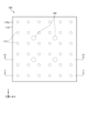
図1は、実施形態に係る加熱装置100をY軸負方向から見た側面図である。以下では、加熱装置100を加熱対象物に接触させる際に加熱対象物側に位置する面が「上面」であり、加熱対象物とは反対側に位置する面が「下面」であるものとする。なお、これに限らず、加熱装置100は、例えば上下反転して使用されてもよく、任意の姿勢で使用されてよい。 Figure 1 is a side view of the heating device 100 according to the embodiment, seen from the negative direction of the Y axis. In the following, when the heating device 100 is brought into contact with the object to be heated, the surface facing the object to be heated is referred to as the "upper surface", and the surface facing the opposite side to the object to be heated is referred to as the "lower surface". However, this is not limited to the above, and the heating device 100 may be used, for example, upside down, or in any position.

図1に示す加熱装置100は、加熱プレート110、固定プレート120、複数のヒータ130、及び支持プレート150を有する。また、加熱装置100は、複数の陽極側集合電極160と、複数の陰極側集合電極170とを有する。陽極側集合電極160と、陰極側集合電極170とは、集合電極の一例である。The heating device 100 shown in Figure 1 has a heating plate 110, a fixed plate 120, multiple heaters 130, and a support plate 150. The heating device 100 also has multiple anode side collection electrodes 160 and multiple cathode side collection electrodes 170. The anode side collection electrode 160 and the cathode side collection electrode 170 are examples of collection electrodes.

加熱プレート110は、例えば金属製の板状部材である。加熱プレート110は、加熱対象物と接触可能な上面110aを有する。すなわち、加熱プレート110の上面110aが加熱対象物を加熱する加熱面となる。上面110aは、例えば、加熱対象物の一例としての金型の加熱に用いられる。加熱プレート110の加熱面とは反対側の下面110b(反対面の一例)には、複数のヒータ130がそれぞれ挿入される複数の凹部113(図3、図5等参照)が位置している。The heating plate 110 is, for example, a plate-like member made of metal. The heating plate 110 has an upper surface 110a that can come into contact with the object to be heated. In other words, the upper surface 110a of the heating plate 110 becomes the heating surface that heats the object to be heated. The upper surface 110a is used, for example, to heat a mold as an example of the object to be heated. The lower surface 110b (an example of the opposite surface) opposite the heating surface of the heating plate 110 has multiple recesses 113 (see Figures 3, 5, etc.) into which multiple heaters 130 are respectively inserted.

複数のヒータ130は、複数の凹部113にそれぞれ挿入される。言い換えれば、複数のヒータ130は、複数の凹部113にそれぞれ位置する。これにより、複数のヒータ130は、加熱面である加熱プレート110の上面110aに対して垂直となるように配置される。このように、複数のヒータ130を加熱プレート110の加熱面に対して垂直に配置することにより、複数のヒータ130と加熱面との間の距離のばらつきが抑制されることから、加熱面の面内での均熱性を向上させることができる。また、ヒータ130は、長手方向に温度分布が生じる。これに対し、複数のヒータ130を加熱プレート110の加熱面に対して垂直に配置することにより、上面110aの中央部と外周部とで、ヒータ130の温度分布に起因する温度差が生じることを抑制することができる。The heaters 130 are inserted into the recesses 113, respectively. In other words, the heaters 130 are located in the recesses 113, respectively. As a result, the heaters 130 are arranged so as to be perpendicular to the upper surface 110a of the heating plate 110, which is the heating surface. In this way, by arranging the heaters 130 perpendicular to the heating surface of the heating plate 110, the variation in the distance between the heaters 130 and the heating surface is suppressed, and the thermal uniformity within the heating surface can be improved. In addition, the heaters 130 have a temperature distribution in the longitudinal direction. In contrast, by arranging the heaters 130 perpendicular to the heating surface of the heating plate 110, it is possible to suppress the occurrence of a temperature difference caused by the temperature distribution of the heaters 130 between the center and the outer periphery of the upper surface 110a.

ここで、ヒータ130の構成について図2を参照して説明する。図2は、実施形態に係るヒータ130の断面図である。Here, the configuration of the heater 130 will be described with reference to Figure 2. Figure 2 is a cross-sectional view of the heater 130 according to the embodiment.

図2に示すように、実施形態に係るヒータ130は、ヒータ本体131と、固定部材132と、陽極側リード電極133と、陰極側リード電極134とを有する。陽極側リード電極133と、陰極側リード電極134とは、リード電極の一例である。2, the heater 130 according to the embodiment has a heater body 131, a fixing member 132, an anode side lead electrode 133, and a cathode side lead electrode 134. The anode side lead electrode 133 and the cathode side lead electrode 134 are examples of lead electrodes.

ヒータ本体131は、セラミックヒータである。ヒータ本体131は、セラミック体の内部に発熱抵抗体131aを有する。ヒータ本体131をセラミックヒータとすることにより、金属製である加熱プレート110とヒータ本体131との間の焼き付きを抑制することができる。したがって、たとえば、ヒータ本体131が加熱プレート110に焼き付くことでヒータ130が交換できなくなるといった不具合が生じにくい。The heater body 131 is a ceramic heater. The heater body 131 has a heating resistor 131a inside the ceramic body. By using a ceramic heater for the heater body 131, it is possible to suppress burning between the metal heating plate 110 and the heater body 131. Therefore, for example, a problem such as the heater body 131 burning to the heating plate 110 and the heater 130 becoming unable to be replaced is unlikely to occur.

ヒータ本体131の長さ、すなわちセラミック体の長さは、例えば、1mm以上200mm以下程度とすることができる。また、セラミック体の外寸は、例えば、0.5mm以上100mm以下程度とすることができる。The length of the heater body 131, i.e., the length of the ceramic body, can be, for example, about 1 mm or more and 200 mm or less. The outer dimensions of the ceramic body can be, for example, about 0.5 mm or more and 100 mm or less.

ヒータ本体131の形状、すなわちセラミック体の形状は、たとえば円柱状である。なお、ヒータ本体131の形状は、円柱状に限らず、例えば楕円柱状または角柱状であってもよい。セラミック体の材料は、例えば、絶縁性を有するセラミックである。セラミック体の材料としては、例えば、酸化物セラミックス、窒化物セラミックスまたは炭化物セラミックス等を使用することができる。The shape of the heater body 131, i.e., the shape of the ceramic body, is, for example, cylindrical. The shape of the heater body 131 is not limited to a cylindrical shape, and may be, for example, an elliptical cylinder or a rectangular cylinder. The material of the ceramic body is, for example, an insulating ceramic. For example, oxide ceramics, nitride ceramics, carbide ceramics, etc. can be used as the material of the ceramic body.

発熱抵抗体131aは、電流が流れることによって発熱する部材である。発熱抵抗体131aは、一方の端部において後述する陽極側リード電極133のコイル部133aに接続される。また、発熱抵抗体131aは、他方の端部において後述する陰極側リード電極134のコイル部134aに接続される。The heating resistor 131a is a member that generates heat when a current flows through it. One end of the heating resistor 131a is connected to a coil portion 133a of the anode lead electrode 133, which will be described later. The other end of the heating resistor 131a is connected to a coil portion 134a of the cathode lead electrode 134, which will be described later.

発熱抵抗体131aは、例えば、タングステン、モリブデンなどを含む高抵抗の導体を含んでよい。発熱抵抗体131aの寸法は、例えば幅を0.1mm以上5mm以下に、厚みを0.05mm以上0.3mm以下に、全長を1mm以上500mm以下にすることができる。また、発熱抵抗体131aは、例えばタングステンカーバイドを含む導電性セラミックスであってもよい。この場合は、セラミック体と発熱抵抗体131aとの熱膨張差を低減できる。これにより、セラミック体と発熱抵抗体131aとの間の熱応力を低減できる。その結果、ヒータ本体131の耐久性を高めることができる。The heating resistor 131a may include a high resistance conductor containing, for example, tungsten, molybdenum, etc. The dimensions of the heating resistor 131a may be, for example, a width of 0.1 mm to 5 mm, a thickness of 0.05 mm to 0.3 mm, and a total length of 1 mm to 500 mm. The heating resistor 131a may also be a conductive ceramic containing, for example, tungsten carbide. In this case, the thermal expansion difference between the ceramic body and the heating resistor 131a can be reduced. This reduces the thermal stress between the ceramic body and the heating resistor 131a. As a result, the durability of the heater body 131 can be increased.

固定部材132は、ヒータ本体131の周面を囲む筒状をなしている。固定部材132は、たとえば、第1部材132aと第2部材132bとを有する。The fixing member 132 is cylindrical and surrounds the circumferential surface of the heater body 131. The fixing member 132 has, for example, a first member 132a and a second member 132b.

第1部材132aの外周面には、おねじ132cが位置している。第1部材132aの材料は、例えば、耐熱性を有する金属材料である。固定部材132の材料としては、例えば、FeまたはNi等を含有する合金を使用することができる。具体的には、固定部材132は、ステンレス鋼、Fe-Ni-Co合金またはNi系耐熱合金等を材料とすることができる。 A male screw 132c is located on the outer peripheral surface of the first member 132a. The material of the first member 132a is, for example, a heat-resistant metal material. The material of the fixing member 132 can be, for example, an alloy containing Fe or Ni. Specifically, the fixing member 132 can be made of stainless steel, an Fe-Ni-Co alloy, a Ni-based heat-resistant alloy, or the like.

第2部材132bは、第1部材132aと陰極側リード電極134のコイル部134aとの間に位置している。第2部材132bの材料は、例えば、絶縁性を有するセラミックである。第2部材132bの材料としては、例えば、アルミナまたは窒化ケイ素等であってよい。The second member 132b is located between the first member 132a and the coil portion 134a of the cathode lead electrode 134. The material of the second member 132b is, for example, an insulating ceramic. The material of the second member 132b may be, for example, alumina or silicon nitride.

陽極側リード電極133および陰極側リード電極134は、ヒータ本体131の周面に固定されている。陽極側リード電極133は、一端が後述する陽極側集合電極160を介して外部電源に接続され、他端が発熱抵抗体131aに電気的に接続される。また、陰極側リード電極134は、一端が後述する陰極側集合電極170を介して外部電源に接続され、他端が発熱抵抗体131aに電気的に接続される。The anode side lead electrode 133 and the cathode side lead electrode 134 are fixed to the peripheral surface of the heater body 131. One end of the anode side lead electrode 133 is connected to an external power source via an anode side assembly electrode 160 described later, and the other end is electrically connected to the heating resistor 131a. One end of the cathode side lead electrode 134 is connected to an external power source via a cathode side assembly electrode 170 described later, and the other end is electrically connected to the heating resistor 131a.

陽極側リード電極133および陰極側リード電極134は、例えば、ニッケル、鉄またはニッケル系耐熱合金等の金属材料を含む線材である。陽極側リード電極133および陰極側リード電極134の断面は、例えば円形状であってもよく、楕円形状、矩形状であってもよい。陽極側リード電極133および陰極側リード電極134の外径は、例えば0.5以上2.0mm以下であってもよい。The anode lead electrode 133 and the cathode lead electrode 134 are wires containing a metal material such as nickel, iron, or a nickel-based heat-resistant alloy. The cross sections of the anode lead electrode 133 and the cathode lead electrode 134 may be, for example, circular, elliptical, or rectangular. The outer diameters of the anode lead electrode 133 and the cathode lead electrode 134 may be, for example, 0.5 to 2.0 mm.

陽極側リード電極133は、コイル部133aと端子部133bとを有する。コイル部133aは、陽極側リード電極133のうち、ヒータ本体131の周面に沿って螺旋状に巻回される部分であり、発熱抵抗体131aの一方の端部に電気的に接続されている。端子部133bは、陽極側リード電極133のうち、コイル部133aからヒータ本体131の外方に引き出された部分である。端子部133bは、ヒータ本体131の後端からヒータ本体131の長手方向外方(ここでは、Z軸負方向)に延びている。The anode lead electrode 133 has a coil portion 133a and a terminal portion 133b. The coil portion 133a is a portion of the anode lead electrode 133 that is wound in a spiral shape around the circumferential surface of the heater body 131 and is electrically connected to one end of the heating resistor 131a. The terminal portion 133b is a portion of the anode lead electrode 133 that is drawn outward from the coil portion 133a of the heater body 131. The terminal portion 133b extends from the rear end of the heater body 131 outward in the longitudinal direction of the heater body 131 (here, in the negative Z-axis direction).

陰極側リード電極134は、コイル部134aと端子部134bとを有する。コイル部134aは、ヒータ本体131の周面に沿って螺旋状に巻回される部分であり、発熱抵抗体131aの他方の端部に電気的に接続されている。端子部134bは、陰極側リード電極134のうち、コイル部134aから引き出された部分である。端子部134bは、ヒータ本体131の周面からヒータ本体131の径方向外方(ここでは、Y軸正方向)に延びている。The cathode lead electrode 134 has a coil portion 134a and a terminal portion 134b. The coil portion 134a is a portion that is wound in a spiral shape along the circumferential surface of the heater body 131 and is electrically connected to the other end of the heating resistor 131a. The terminal portion 134b is a portion of the cathode lead electrode 134 that is drawn out from the coil portion 134a. The terminal portion 134b extends from the circumferential surface of the heater body 131 radially outward of the heater body 131 (here, in the positive Y-axis direction).

このように、ヒータ130のリード電極(陽極側リード電極133および陰極側リード電極134)は、ヒータ本体131の周面に沿って位置するコイル部133a,134aと、コイル部133a,134aから引き出された端子部133b,134bとを有する。このように構成されたヒータ130は、コイル部133a,134aがバネとして機能することで、応力が集中しにくい。したがって、このように構成されたヒータ130は、耐久性が高い。 Thus, the lead electrodes (anode side lead electrode 133 and cathode side lead electrode 134) of the heater 130 have coil portions 133a, 134a located along the circumferential surface of the heater body 131, and terminal portions 133b, 134b drawn out from the coil portions 133a, 134a. The heater 130 configured in this manner is less susceptible to stress concentration because the coil portions 133a, 134a function as springs. Therefore, the heater 130 configured in this manner has high durability.

なお、ここでは、陽極側リード電極133が、陰極側リード電極134よりもヒータ本体131の後端側に位置する場合の例について説明したが、陽極側リード電極133および陰極側リード電極134の位置関係は逆であってもよい。すなわち、図2に示す陽極側リード電極133の位置に設けられるリード電極は、陰極側リード電極134であってもよい。また、図2に示す陰極側リード電極134の位置に設けられるリード電極は、陽極側リード電極133であってもよい。 Note that, although an example has been described here in which the anode side lead electrode 133 is located closer to the rear end of the heater body 131 than the cathode side lead electrode 134, the positional relationship between the anode side lead electrode 133 and the cathode side lead electrode 134 may be reversed. That is, the lead electrode provided at the position of the anode side lead electrode 133 shown in FIG. 2 may be the cathode side lead electrode 134. Also, the lead electrode provided at the position of the cathode side lead electrode 134 shown in FIG. 2 may be the anode side lead electrode 133.

加熱装置100が有する複数のヒータ130は、加熱プレート110の下面110bに形成された複数の凹部113に挿入される。図3は、実施形態に係る加熱装置100をZ軸正方向から見た平面図である。The heaters 130 of the heating device 100 are inserted into recesses 113 formed in the lower surface 110b of the heating plate 110. Figure 3 is a plan view of the heating device 100 according to the embodiment, viewed from the positive direction of the Z axis.

図3には、加熱面である加熱プレート110の上面110aが矩形板状に示されるとともに、複数の凹部113の位置が破線で示されている。一例として、図3に示す複数の凹部113は、6行6列で配置されている。すなわち、実施形態に係る加熱プレート110は、合計36個の凹部113を有している。なお、複数の凹部113の配置および数は、図示の例に限定されない。 In Figure 3, the upper surface 110a of the heating plate 110, which is the heating surface, is shown as a rectangular plate, and the positions of the multiple recesses 113 are indicated by dashed lines. As an example, the multiple recesses 113 shown in Figure 3 are arranged in 6 rows and 6 columns. In other words, the heating plate 110 according to the embodiment has a total of 36 recesses 113. Note that the arrangement and number of the multiple recesses 113 are not limited to the example shown in the figure.

図1に戻り、固定プレート120について説明する。固定プレート120は、例えば金属製の板状部材であり、加熱プレート110から離隔して配置されている。固定プレート120には、複数の凹部113にそれぞれ挿入される複数のヒータ130が固定されている。固定プレート120に対するヒータ130の固定態様については、後述する。Returning to FIG. 1, the fixed plate 120 will be described. The fixed plate 120 is, for example, a plate-shaped member made of metal, and is disposed at a distance from the heating plate 110. A plurality of heaters 130 are fixed to the fixed plate 120 and are inserted into the plurality of recesses 113, respectively. The manner in which the heaters 130 are fixed to the fixed plate 120 will be described later.

支持プレート150は、固定プレート120から離れた状態で、複数の柱状部材151によって固定プレート120に固定されている。支持プレート150が固定プレート120から離れて位置することにより、各ヒータ130の端子部133b,134bを配置するための空間、言い換えれば、後述する陽極側集合電極160および陰極側集合電極170を配置するための空間を支持プレート150と固定プレート120との間に確保することが可能となる。なお、支持プレート150及び複数の柱状部材151は、必要に応じて省略されてもよい。The support plate 150 is fixed to the fixed plate 120 by a plurality of columnar members 151 while being spaced apart from the fixed plate 120. By positioning the support plate 150 away from the fixed plate 120, it is possible to secure a space between the support plate 150 and the fixed plate 120 for arranging the terminal portions 133b, 134b of each heater 130, in other words, a space for arranging the anode side assembly electrode 160 and the cathode side assembly electrode 170 described later. The support plate 150 and the plurality of columnar members 151 may be omitted as necessary.

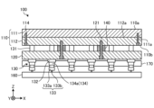
図4は、図3に示すIV-IV線における断面図である。また、図5は、図3に示すV-V線における断面図である。なお、図4及び図5では、支持プレート150及び複数の柱状部材151の図示が省略されている。 Figure 4 is a cross-sectional view taken along line IV-IV in Figure 3. Also, Figure 5 is a cross-sectional view taken along line V-V in Figure 3. Note that in Figures 4 and 5, the support plate 150 and the multiple columnar members 151 are omitted from illustration.

図4及び図5に示すように、加熱装置100は、複数のヒータ130が固定プレート120に固定されるとともに加熱プレート110の複数の凹部113にそれぞれ挿入されて構成される。As shown in Figures 4 and 5, the heating device 100 is configured by fixing a plurality of heaters 130 to a fixed plate 120 and inserting them into a plurality of recesses 113 of the heating plate 110.

加熱プレート110は、第1のプレート部材111及び第2のプレート部材112を有する。The heating plate 110 has a first plate member 111 and a second plate member 112.

第1のプレート部材111は、加熱面である加熱プレート110の上面110aを有する板状部材である。第1のプレート部材111は、例えばボルト等の固定部材114によって第2のプレート部材112に接合されている。すなわち、第1のプレート部材111の上面110aとは反対側の下面111aは、第2のプレート部材112に接合される接合面である。The first plate member 111 is a plate-like member having an upper surface 110a of the heating plate 110, which is a heating surface. The first plate member 111 is joined to the second plate member 112 by a fixing member 114, such as a bolt. In other words, the lower surface 111a of the first plate member 111, opposite to the upper surface 110a, is a joining surface that is joined to the second plate member 112.

第2のプレート部材112は、第1のプレート部材111の接合面に接合される被接合面となる上面112aと、上面112aの反対側に位置する下面110bとを有する板状部材である。下面110bには、複数の貫通孔112bが形成されており、複数の貫通孔112bの各々から第1のプレート部材111の下面111aが露出する。The second plate member 112 is a plate-like member having an upper surface 112a, which is a surface to be joined to the joining surface of the first plate member 111, and a lower surface 110b located on the opposite side of the upper surface 112a. A plurality of through holes 112b are formed in the lower surface 110b, and the lower surface 111a of the first plate member 111 is exposed from each of the plurality of through holes 112b.

複数の凹部113の各々は、複数の貫通孔112bの各々と複数の貫通孔112bの各々から露出する第1のプレート部材111の下面111aとによって形成されている。すなわち、各貫通孔112bの内壁面が各凹部113の内側面を形成し、第1のプレート部材111の下面111aが各凹部113の底面(図5に示す姿勢においては天井面)を形成している。Each of the multiple recesses 113 is formed by each of the multiple through holes 112b and the lower surface 111a of the first plate member 111 exposed from each of the multiple through holes 112b. That is, the inner wall surface of each through hole 112b forms the inner side surface of each recess 113, and the lower surface 111a of the first plate member 111 forms the bottom surface of each recess 113 (the ceiling surface in the position shown in FIG. 5).

固定プレート120は、固定プレート120と加熱プレート110との間に隙間が形成された状態で、例えばボルト等の連結部材121によって加熱プレート110に連結されることにより、加熱プレート110から離隔して配置されている。固定プレート120を加熱プレート110から離隔して配置させることにより、固定プレート120に対する複数のヒータ130の固定部分(例えば、後述の固定孔120a)の昇温を抑制することができる。一方で、固定プレート120によって加熱プレート110から奪われる熱が低減するため、加熱プレート110の昇温を促進することができる。The fixing plate 120 is connected to the heating plate 110 by a connecting member 121 such as a bolt, with a gap formed between the fixing plate 120 and the heating plate 110, and is disposed at a distance from the heating plate 110. By disposing the fixing plate 120 at a distance from the heating plate 110, it is possible to suppress the rise in temperature of the fixing portions (e.g., the fixing holes 120a described below) of the multiple heaters 130 relative to the fixing plate 120. On the other hand, the heat taken from the heating plate 110 by the fixing plate 120 is reduced, so that the rise in temperature of the heating plate 110 can be promoted.

固定プレート120は、複数の凹部113に対応する位置に複数の固定孔120aを有する。複数の固定孔120aには、複数のヒータ130がそれぞれ挿通されて固定されている。以下では、説明の便宜上、特に区別する必要がない場合には、複数の凹部113、複数の固定孔120a及び複数のヒータ130をそれぞれ単に「凹部113」、「固定孔120a」及び「ヒータ130」と呼ぶ。The fixing plate 120 has a plurality of fixing holes 120a at positions corresponding to the plurality of recesses 113. A plurality of heaters 130 are inserted and fixed into the plurality of fixing holes 120a. In the following, for convenience of explanation, unless there is a particular need to distinguish between the plurality of recesses 113, the plurality of fixing holes 120a, and the plurality of heaters 130 will be referred to simply as "recesses 113," "fixing holes 120a," and "heaters 130," respectively.

ヒータ130のヒータ本体131は、固定孔120aを貫通しており、その先端が凹部113に挿入されている。ヒータ本体131の基端部は、固定プレート120の下面よりも加熱面である加熱プレート110の上面110aから離れる方向に突出している。ヒータ本体131の基端部には、上述した陽極側リード電極133および陰極側リード電極134が位置している。加熱面である加熱プレート110の上面110aから離れる方向に突出するヒータ本体131の基端部に陽極側リード電極133および陰極側リード電極134を設けることにより、加熱面から陽極側リード電極133および陰極側リード電極134を遠ざけることができる。したがって、かかる構成によれば、陽極側リード電極133および陰極側リード電極134への熱伝達を抑制することができる。The heater body 131 of the heater 130 penetrates the fixing hole 120a, and its tip is inserted into the recess 113. The base end of the heater body 131 protrudes in a direction away from the upper surface 110a of the heating plate 110, which is the heating surface, beyond the lower surface of the fixing plate 120. The above-mentioned anode side lead electrode 133 and cathode side lead electrode 134 are located at the base end of the heater body 131. By providing the anode side lead electrode 133 and the cathode side lead electrode 134 at the base end of the heater body 131 protruding in a direction away from the upper surface 110a of the heating plate 110, which is the heating surface, the anode side lead electrode 133 and the cathode side lead electrode 134 can be kept away from the heating surface. Therefore, with this configuration, heat transfer to the anode side lead electrode 133 and the cathode side lead electrode 134 can be suppressed.

ヒータ130の固定部材132は、固定孔120aの内壁との間に隙間を空けてヒータ本体131を固定孔120aに固定する。具体的には、固定孔120aの内壁の加熱プレート110とは反対側に位置する一部には、めねじが形成されている。一方で、固定部材132は、第1部材132aの外周部におねじ132cを有する。固定部材132は、ヒータ本体131が固定孔120aに挿通される際に、おねじ132cを固定孔120aのめねじに嵌合させることで、ヒータ本体131と固定孔120aの内壁との間に隙間が形成された状態で、ヒータ本体131を固定孔120aに固定する。The fixing member 132 of the heater 130 fixes the heater body 131 to the fixing hole 120a with a gap between the fixing member 132 and the inner wall of the fixing hole 120a. Specifically, a female thread is formed on a part of the inner wall of the fixing hole 120a located on the opposite side to the heating plate 110. On the other hand, the fixing member 132 has a male thread 132c on the outer periphery of the first member 132a. When the heater body 131 is inserted into the fixing hole 120a, the fixing member 132 fixes the heater body 131 to the fixing hole 120a with a gap formed between the heater body 131 and the inner wall of the fixing hole 120a by fitting the male thread 132c into the female thread of the fixing hole 120a.

このように、ヒータ本体131が固定孔120aの内壁との間に隙間を空けて固定孔120aに固定されることにより、固定プレート120はヒータ本体131からの熱を受け難い。これにより、固定プレート120の温度上昇が抑制されることから、固定プレート120から、陽極側リード電極133および陰極側リード電極134が設けられるヒータ本体131の基端部へ向けて放射される熱が抑制される。このため、実施形態に係る加熱装置100によれば、ヒータ130における陽極側リード電極133および陰極側リード電極134の劣化を低減することができる。In this way, the heater body 131 is fixed to the fixing hole 120a with a gap between the heater body 131 and the inner wall of the fixing hole 120a, so that the fixing plate 120 is less likely to receive heat from the heater body 131. This suppresses the temperature rise of the fixing plate 120, and suppresses the heat radiated from the fixing plate 120 toward the base end of the heater body 131 where the anode side lead electrode 133 and the cathode side lead electrode 134 are provided. Therefore, according to the heating device 100 of the embodiment, deterioration of the anode side lead electrode 133 and the cathode side lead electrode 134 in the heater 130 can be reduced.

加熱プレート110と固定プレート120との間には、スペーサ部材140が配置されている。スペーサ部材140は、筒状をなし、連結部材121を挿通させている。加熱プレート110と固定プレート120との間にスペーサ部材140を設けることにより、加熱プレート110と固定プレート120とが離隔した状態を保つことができるとともに、加熱プレート110と固定プレート120との距離を保つことができる。したがって、かかる構成によれば、加熱プレート110からの伝熱に伴う固定プレート120の温度上昇を継続的に抑えることができる。A spacer member 140 is disposed between the heating plate 110 and the fixed plate 120. The spacer member 140 is cylindrical, and the connecting member 121 is inserted through it. By providing the spacer member 140 between the heating plate 110 and the fixed plate 120, the heating plate 110 and the fixed plate 120 can be kept apart, and the distance between the heating plate 110 and the fixed plate 120 can be maintained. Therefore, with this configuration, the temperature rise of the fixed plate 120 due to heat transfer from the heating plate 110 can be continuously suppressed.

スペーサ部材140の材料は、例えば、耐熱性を有するセラミックであることが好ましい。スペーサ部材140の材料としては、例えば、酸化物セラミックス、窒化物セラミックスまたは炭化物セラミックス等を使用することができる。これにより、スペーサ部材140の熱膨張及び熱収縮を低減することができることから、スペーサ部材140の消耗を低減することができる。The material of the spacer member 140 is preferably, for example, a heat-resistant ceramic. For example, oxide ceramics, nitride ceramics, or carbide ceramics can be used as the material of the spacer member 140. This reduces the thermal expansion and thermal contraction of the spacer member 140, thereby reducing wear of the spacer member 140.

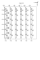
図1に戻る。陽極側集合電極160は、複数のヒータ130の陽極側リード電極133に電気的に接続されている。実施形態において、加熱装置100は、36個のヒータ130を有しており、陽極側集合電極160は、これら36個のヒータ130のうち一列に並んだ6個のヒータ130の陽極側リード電極133に電気的に接続されている。加熱装置100は、合計で6個の陽極側集合電極160を有している(図7参照)。Returning to FIG. 1, the anode side assembly electrode 160 is electrically connected to the anode side lead electrodes 133 of the multiple heaters 130. In an embodiment, the heating device 100 has 36 heaters 130, and the anode side assembly electrode 160 is electrically connected to the anode side lead electrodes 133 of six heaters 130 that are aligned in a row among these 36 heaters 130. The heating device 100 has a total of six anode side assembly electrodes 160 (see FIG. 7).

また、陰極側集合電極170は、複数のヒータ130の陰極側リード電極134に電気的に接続されている。実施形態において、加熱装置100は、36個のヒータ130を有しており、陰極側集合電極170は、これら36個のヒータ130のうち一列に並んだ6個のヒータ130の陰極側リード電極134に電気的に接続されている。加熱装置100は、合計で6個の陰極側集合電極170を有している(図9参照)。In addition, the cathode side assembly electrode 170 is electrically connected to the cathode side lead electrodes 134 of the multiple heaters 130. In the embodiment, the heating device 100 has 36 heaters 130, and the cathode side assembly electrode 170 is electrically connected to the cathode side lead electrodes 134 of six heaters 130 that are aligned in a row among these 36 heaters 130. The heating device 100 has a total of six cathode side assembly electrodes 170 (see FIG. 9).

このように、実施形態に係る加熱装置100は、加熱装置100が有する複数のヒータ130のうち2以上のヒータ130が有する2以上の陽極側リード電極133に接続された陽極側集合電極160を有する。また、実施形態に係る加熱装置100は、加熱装置100が有する複数のヒータ130のうち2以上のヒータ130が有する2以上の陰極側リード電極134に接続された陰極側集合電極170を有する。Thus, the heating device 100 according to the embodiment has an anode side assembly electrode 160 connected to two or more anode side lead electrodes 133 of two or more of the heaters 130 included in the heating device 100. The heating device 100 according to the embodiment also has a cathode side assembly electrode 170 connected to two or more cathode side lead electrodes 134 of two or more of the heaters 130 included in the heating device 100.

複数(ここでは、6個)のヒータ130で発生した熱は、リード電極を介して1つの集合電極に伝えられる。これにより、各ヒータ130で発生した熱が各ヒータ130のリード電極からバラバラに散逸することを抑制することができる。したがって、実施形態に係る加熱装置100によれば、均熱性の向上を図ることができる。The heat generated by the multiple heaters 130 (here, six) is transferred to one collective electrode via the lead electrodes. This prevents the heat generated by each heater 130 from dissipating separately from the lead electrodes of each heater 130. Therefore, the heating device 100 according to the embodiment can improve thermal uniformity.

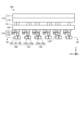
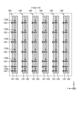
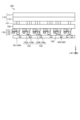
以下、陽極側集合電極160および陰極側集合電極170の構成について図6~図9を参照してより具体的に説明する。図6は、実施形態に係る加熱装置100をX軸負方向から見た側面図である。図7は、図6に示すVII-VII線矢視における断面図である。図8は、実施形態に係る加熱装置100をY軸正方向から見た側面図である。図9は、実施形態に係る複数の陰極側集合電極170をZ軸負方向から見た平面図である。 Below, the configuration of the anode side collection electrode 160 and the cathode side collection electrode 170 will be described in more detail with reference to Figures 6 to 9. Figure 6 is a side view of the heating device 100 according to the embodiment, as viewed from the negative direction of the X-axis. Figure 7 is a cross-sectional view taken along the line VII-VII shown in Figure 6. Figure 8 is a side view of the heating device 100 according to the embodiment, as viewed from the positive direction of the Y-axis. Figure 9 is a plan view of multiple cathode side collection electrodes 170 according to the embodiment, as viewed from the negative direction of the Z-axis.

図6および図7に示すように、陽極側集合電極160は、第1金属板161と、第2金属板162と、複数の固定部材163とを有する。第1金属板161および第2金属板162は、断面視矩形状の金属製の板材である。固定部材163は、第1金属板161と第2金属板162とを着脱自在に固定する。固定部材163は、たとえばボルトである。6 and 7, the anode side assembly electrode 160 has a first metal plate 161, a second metal plate 162, and a number of fixing members 163. The first metal plate 161 and the second metal plate 162 are metallic plates having a rectangular cross-sectional shape. The fixing members 163 fix the first metal plate 161 and the second metal plate 162 in a detachable manner. The fixing members 163 are, for example, bolts.

陽極側集合電極160は、第1金属板161と第2金属板162とで複数の陽極側リード電極133の端子部133bを挟み込むことにより、複数の陽極側リード電極133と電気的に接続される。具体的には、実施形態において、第1金属板161および第2金属板162は、X軸方向に沿って延在しており、X軸方向に沿って並べられた複数(ここでは、6個)の端子部133bを挟み込んでいる。The anode side assembly electrode 160 is electrically connected to the multiple anode side lead electrodes 133 by sandwiching the terminal portions 133b of the multiple anode side lead electrodes 133 between the first metal plate 161 and the second metal plate 162. Specifically, in the embodiment, the first metal plate 161 and the second metal plate 162 extend along the X-axis direction and sandwich multiple (here, six) terminal portions 133b arranged along the X-axis direction.

かかる構成とすることにより、複数の陽極側リード電極133を一直線に接続することができるため、複数の陽極側リード電極133を最短で接続することができる。また、端子部133bの長さにバラツキがある場合であっても、接続が容易である。With this configuration, the multiple anode side lead electrodes 133 can be connected in a straight line, so that the multiple anode side lead electrodes 133 can be connected in the shortest possible way. In addition, even if there is variation in the length of the terminal portion 133b, the connection is easy.

また、固定部材163による第1金属板161と第2金属板162との固定は解除可能である。このため、たとえば複数のヒータ130のうちいずれか1個が故障した場合に、故障した1個だけを交換することができる。このように、実施形態に係る加熱装置100によれば、ヒータ130の交換が容易である。 The fixing of the first metal plate 161 and the second metal plate 162 by the fixing member 163 can be released. Therefore, for example, if one of the multiple heaters 130 breaks down, it is possible to replace only the broken one. In this way, according to the heating device 100 of the embodiment, the heater 130 can be easily replaced.

図7に示すように、複数(ここでは、6個)の陽極側集合電極160は、Y軸方向に沿って並べられている。図7に示すように、加熱プレート110の加熱面である上面110aに向かって視た平面透視において、各陽極側集合電極160と端子部133bとの接続位置は、加熱プレート110の上面110aと重なっている。このように、加熱領域の範囲内において陽極側集合電極160と端子部133bとを接続することで、たとえば、加熱領域の外方において陽極側集合電極160と端子部133bとを接続する場合と比較して、各ヒータ130から加熱装置100の外方への熱の散逸を抑制することができる。したがって、実施形態に係る加熱装置100によれば、均熱性をさらに高めることができる。As shown in FIG. 7, multiple (six in this example) anode side assembly electrodes 160 are arranged along the Y-axis direction. As shown in FIG. 7, in a plan view seen toward the upper surface 110a, which is the heating surface of the heating plate 110, the connection positions of each anode side assembly electrode 160 and the terminal portion 133b overlap with the upper surface 110a of the heating plate 110. By connecting the anode side assembly electrode 160 and the terminal portion 133b within the range of the heating area in this way, it is possible to suppress the dissipation of heat from each heater 130 to the outside of the heating device 100, for example, compared to the case where the anode side assembly electrode 160 and the terminal portion 133b are connected outside the heating area. Therefore, according to the heating device 100 of the embodiment, the thermal uniformity can be further improved.

図6、図8および図9に示すように、陰極側集合電極170は、第1金属板171と、第2金属板172と、複数の固定部材173とを有する。第1金属板171および第2金属板172は、断面視矩形状の金属製の板材である。固定部材173は、第1金属板171と第2金属板172とを着脱自在に固定する。固定部材173は、たとえばボルトである。6, 8 and 9, the cathode side assembly electrode 170 has a first metal plate 171, a second metal plate 172, and a number of fixing members 173. The first metal plate 171 and the second metal plate 172 are metal plates having a rectangular cross-sectional shape. The fixing members 173 fix the first metal plate 171 and the second metal plate 172 in a detachable manner. The fixing members 173 are, for example, bolts.

陰極側集合電極170は、第1金属板171と第2金属板172とで複数の陰極側リード電極134の端子部134bを挟み込むことにより、複数の陰極側リード電極134と電気的に接続される。具体的には、実施形態において、第1金属板171および第2金属板172は、X軸方向に沿って延在しており、X軸方向に沿って並べられた複数(ここでは、6個)の端子部134bを挟み込んでいる(図8および図9参照)。The cathode side assembly electrode 170 is electrically connected to the multiple cathode side lead electrodes 134 by sandwiching the terminal portions 134b of the multiple cathode side lead electrodes 134 between the first metal plate 171 and the second metal plate 172. Specifically, in the embodiment, the first metal plate 171 and the second metal plate 172 extend along the X-axis direction and sandwich multiple (here, six) terminal portions 134b arranged along the X-axis direction (see Figures 8 and 9).

かかる構成とすることにより、複数の陰極側リード電極134を一直線に接続することができるため、複数の陰極側リード電極134を最短で接続することができる。また、端子部134bの長さにバラツキがある場合であっても、接続が容易である。With this configuration, the multiple cathode side lead electrodes 134 can be connected in a straight line, so that the multiple cathode side lead electrodes 134 can be connected in the shortest possible way. In addition, even if there is variation in the length of the terminal portion 134b, the connection is easy.

また、固定部材173による第1金属板171と第2金属板172との固定は解除可能であるため、たとえば複数のヒータ130のうちいずれか1個が故障した場合に、故障した1個だけを交換することができる。このように、実施形態に係る加熱装置100によれば、ヒータ130の交換が容易である。In addition, since the fixing of the first metal plate 171 and the second metal plate 172 by the fixing member 173 can be released, for example, if one of the heaters 130 breaks down, it is possible to replace only the broken one. In this way, according to the heating device 100 according to the embodiment, the heater 130 can be easily replaced.

図9に示すように、複数(ここでは、6個)の陰極側集合電極170は、Y軸方向に沿って並べられている。図9に示すように、加熱プレート110の加熱面である上面110aと垂直な方向から見た平面視において、各陰極側集合電極170と端子部134bとの接続位置は、加熱プレート110の上面110aと重複している。このように、加熱領域の範囲内において陰極側集合電極170と端子部134bとを接続することで、たとえば、加熱領域の外方において陰極側集合電極170と端子部134bとを接続する場合と比較して、各ヒータ130から加熱装置100の外方への熱の散逸を抑制することができる。したがって、実施形態に係る加熱装置100によれば、均熱性をさらに高めることができる。As shown in FIG. 9, multiple (six in this example) cathode side assembly electrodes 170 are arranged along the Y-axis direction. As shown in FIG. 9, in a plan view perpendicular to the upper surface 110a, which is the heating surface of the heating plate 110, the connection positions of each cathode side assembly electrode 170 and the terminal portion 134b overlap with the upper surface 110a of the heating plate 110. In this way, by connecting the cathode side assembly electrode 170 and the terminal portion 134b within the range of the heating area, it is possible to suppress the dissipation of heat from each heater 130 to the outside of the heating device 100, for example, compared to the case where the cathode side assembly electrode 170 and the terminal portion 134b are connected outside the heating area. Therefore, according to the heating device 100 of the embodiment, the thermal uniformity can be further improved.

また、実施形態に係る加熱装置100は、2つの金属板でリード電極を挟み込む構成を陽極側および陰極側の両方において採用しているため、上記構成を陽極側および陰極側の一方にのみ採用する場合と比較して、均熱性をさらに高めることができる。 In addition, the heating device 100 according to the embodiment employs a configuration in which the lead electrode is sandwiched between two metal plates on both the anode side and the cathode side, thereby further improving thermal uniformity compared to a case in which the above configuration is employed on only one of the anode side and the cathode side.

また、図7~図9に示すように、陽極側集合電極160と陰極側集合電極170とは、平行である。かかる構成とすることで、陽極側集合電極160の熱膨張または熱収縮の方向と、陰極側集合電極170の熱膨張または熱収縮の方向とが揃うため、ヒータ130に剪断方向の応力がかかり難くなる。したがって、加熱装置100によれば、複数のヒータ130の耐久性を高めることができる。 As shown in Figures 7 to 9, the anode side assembly electrode 160 and the cathode side assembly electrode 170 are parallel. With this configuration, the direction of thermal expansion or contraction of the anode side assembly electrode 160 and the direction of thermal expansion or contraction of the cathode side assembly electrode 170 are aligned, making it difficult for shear stress to be applied to the heater 130. Therefore, the heating device 100 can increase the durability of the multiple heaters 130.

(第1変形例)
図10は、第1変形例に係る陽極側集合電極160の断面図である。図10に示すように、陽極側集合電極160の第1金属板161は、第2金属板162との対向面(第1対向面の一例)に凹部161a(第1凹部の一例)を有していてもよい。また、陽極側集合電極160の第2金属板162は、第1金属板161との対向面(第2対向面の一例)に凹部162a(第2凹部の一例)を有していてもよい。凹部161a,162aは、たとえば、端子部133bの延在方向(ここでは、Z軸方向)に沿って延在する溝形状を有している。
(First Modification)
Fig. 10 is a cross-sectional view of the anode-side assembly electrode 160 according to the first modification. As shown in Fig. 10, the first metal plate 161 of the anode-side assembly electrode 160 may have a recess 161a (an example of a first recess) on a surface (an example of a first opposing surface) facing the second metal plate 162. The second metal plate 162 of the anode-side assembly electrode 160 may have a recess 162a (an example of a second recess) on a surface (an example of a second opposing surface) facing the first metal plate 161. The recesses 161a and 162a have, for example, a groove shape extending along the extension direction (here, the Z-axis direction) of the terminal portion 133b.

このように、陽極側集合電極160は、第1金属板161および第2金属板162に凹部161a,162aを有していてもよい。かかる構成とすることにより、第1金属板161および第2金属板162をバネとして機能させることができる。これにより、端子部133bを挟む力を長期間にわたって維持することができる。In this way, the anode side assembly electrode 160 may have recesses 161a, 162a in the first metal plate 161 and the second metal plate 162. With this configuration, the first metal plate 161 and the second metal plate 162 can function as springs. This makes it possible to maintain the force clamping the terminal portion 133b for a long period of time.

また、第1金属板161の凹部161aと第2金属板162の凹部162aとは対向していてもよい。かかる構成とすることにより、第1金属板161と第2金属板162とによるバネの力を各端子部133bに適切に伝えることができる。In addition, the recess 161a of the first metal plate 161 and the recess 162a of the second metal plate 162 may face each other. With this configuration, the spring force of the first metal plate 161 and the second metal plate 162 can be appropriately transmitted to each terminal portion 133b.

なお、凹部161aと凹部162aとは、必ずしも対向していることを要しない。また、陽極側集合電極160は、第1金属板161および第2金属板162の一方にのみ凹部161a,162aを有していてもよい。In addition, the recesses 161a and 162a do not necessarily need to face each other. In addition, the anode side assembly electrode 160 may have recesses 161a, 162a only on one of the first metal plate 161 and the second metal plate 162.

ここでは、陽極側集合電極160の第1金属板161および第2金属板162が凹部161a,162aを有する場合の例について説明したが、陰極側集合電極170の第1金属板171および第2金属板172も同様の凹部を有していてもよい。すなわち、陰極側集合電極170の第1金属板171は、第2金属板172との対向面に凹部を有していてもよい。また、陰極側集合電極170の第2金属板172は、第1金属板171との対向面に凹部を有していてもよい。また、第1金属板171の凹部と第2金属板172の凹部とは対向していてもよい。Here, an example has been described in which the first metal plate 161 and the second metal plate 162 of the anode side assembly electrode 160 have recesses 161a, 162a, but the first metal plate 171 and the second metal plate 172 of the cathode side assembly electrode 170 may also have similar recesses. That is, the first metal plate 171 of the cathode side assembly electrode 170 may have a recess on the surface facing the second metal plate 172. Also, the second metal plate 172 of the cathode side assembly electrode 170 may have a recess on the surface facing the first metal plate 171. Also, the recess of the first metal plate 171 and the recess of the second metal plate 172 may face each other.

(第2変形例)
図11は、第2変形例に係る陽極側集合電極160の断面図である。図11に示すように、陽極側集合電極160は、たとえば1つの金属板165を有する。金属板165は、金属板165の長手方向(ここでは、X軸方向)に沿って並べられた複数の挿通穴165aを有する。挿通穴165aは、陽極側リード電極133の端子部133bの延在方向(ここでは、Z軸方向)に沿って延在して金属板165を貫通する貫通孔である。各挿通穴165aには、陽極側リード電極133の端子部133bが挿通される。言い換えると、陽極側リード電極133は、挿通穴165aに位置している。
(Second Modification)
Fig. 11 is a cross-sectional view of an anode-side assembly electrode 160 according to a second modified example. As shown in Fig. 11, the anode-side assembly electrode 160 has, for example, one metal plate 165. The metal plate 165 has a plurality of insertion holes 165a arranged along the longitudinal direction of the metal plate 165 (here, the X-axis direction). The insertion holes 165a are through holes that extend along the extension direction of the terminal portion 133b of the anode-side lead electrode 133 (here, the Z-axis direction) and penetrate the metal plate 165. The terminal portion 133b of the anode-side lead electrode 133 is inserted into each insertion hole 165a. In other words, the anode-side lead electrode 133 is located in the insertion hole 165a.

また、金属板165は、複数の挿通穴165aごとに、挿通穴165aに連通する固定用穴165bを有していてもよい。かかる固定用穴165bには、陽極側リード電極133の端子部133bを固定するための固定部材166が挿通される。固定部材166は、たとえばボルトであり、固定用穴165bの内面にはネジ溝が形成されている。陽極側リード電極133の端子部133bは、挿通穴165aの内面と固定用穴165bに挿通された固定部材166とに挟まれる。これにより、端子部133bは、陽極側集合電極160と電気的に接続される。In addition, the metal plate 165 may have a fixing hole 165b for each of the multiple insertion holes 165a that communicates with the insertion hole 165a. A fixing member 166 for fixing the terminal portion 133b of the anode side lead electrode 133 is inserted into the fixing hole 165b. The fixing member 166 is, for example, a bolt, and a thread groove is formed on the inner surface of the fixing hole 165b. The terminal portion 133b of the anode side lead electrode 133 is sandwiched between the inner surface of the insertion hole 165a and the fixing member 166 inserted into the fixing hole 165b. As a result, the terminal portion 133b is electrically connected to the anode side assembly electrode 160.

かかる構成とすることにより、たとえば、端子部133bの太さにバラツキがある場合であっても、複数の端子部133bを陽極側集合電極160に適切に接続することができる。 By adopting such a configuration, for example, even if there is variation in the thickness of the terminal portions 133b, the multiple terminal portions 133b can be appropriately connected to the anode side collection electrode 160.

なお、端子部133bは、少なくとも金属板165と接触していればよい。このため、陽極側集合電極160の金属板165は、必ずしも固定用穴165bおよび固定部材166を備えることを要しない。この場合、たとえば、挿通穴165aの径を端子部133bよりもわずかに大きい程度とすることで、端子部133bと固定用穴165bとの接触性を高めることができる。また、挿通穴165aにろう材または、はんだ材等を充填することによって、金属板165と端子部133bとを電気的に接続してもよい。It is sufficient that the terminal portion 133b is in contact with at least the metal plate 165. Therefore, the metal plate 165 of the anode side assembly electrode 160 does not necessarily have to have the fixing hole 165b and the fixing member 166. In this case, for example, the diameter of the insertion hole 165a is made slightly larger than that of the terminal portion 133b, thereby improving the contact between the terminal portion 133b and the fixing hole 165b. In addition, the metal plate 165 and the terminal portion 133b may be electrically connected by filling the insertion hole 165a with a brazing material, a solder material, or the like.

ここでは、陽極側集合電極160が複数の挿通穴165aが形成された金属板165を有する場合の例について説明したが、陰極側集合電極170も、第2変形例に係る陽極側集合電極160と同様の構成を有していてもよい。すなわち、陰極側集合電極170は、複数の挿通穴が形成された金属板を有していてもよい。また、陰極側集合電極170は、複数の挿通穴ごとに、挿通穴に連通する固定用穴を有していてもよい。Here, an example has been described in which the anode side assembly electrode 160 has a metal plate 165 with multiple insertion holes 165a formed therein, but the cathode side assembly electrode 170 may also have a configuration similar to that of the anode side assembly electrode 160 according to the second modified example. That is, the cathode side assembly electrode 170 may have a metal plate with multiple insertion holes formed therein. In addition, the cathode side assembly electrode 170 may have a fixing hole for each of the multiple insertion holes that communicates with the insertion hole.

(第3変形例)
図12は、第3変形例に係る複数の陽極側集合電極160をX軸負方向から見た側面図である。図12に示すように、複数の陽極側集合電極160のうち少なくとも一つ(異位置集合電極の一例)は、加熱プレート110の加熱面である上面110a(図1等参照)と垂直な方向(ここでは、Z軸方向)における位置が他の陽極側集合電極160と異なっていてもよい。かかる構成とすることにより、複数の陽極側集合電極160をより高密度に配置させることができる。また、複数の陽極側集合電極160の高さ位置がずれることで、複数の陽極側集合電極160の放熱性を向上させることができる。
(Third Modification)
Fig. 12 is a side view of a plurality of anode side assembly electrodes 160 according to the third modified example, seen from the negative direction of the X-axis. As shown in Fig. 12, at least one of the plurality of anode side assembly electrodes 160 (one example of a different position assembly electrode) may be located at a different position from the other anode side assembly electrodes 160 in a direction perpendicular to the upper surface 110a (see Fig. 1, etc.), which is the heating surface of the heating plate 110 (here, the Z-axis direction). With this configuration, the plurality of anode side assembly electrodes 160 can be arranged at a higher density. In addition, by shifting the height positions of the plurality of anode side assembly electrodes 160, the heat dissipation of the plurality of anode side assembly electrodes 160 can be improved.

ここでは、複数の陽極側集合電極160の高さ位置にバラツキを有する場合の例について説明したが、加熱装置100は、複数の陰極側集合電極170の高さ位置にバラツキを有していてもよい。すなわち、複数の陰極側集合電極170のうち少なくとも一つ(異位置集合電極の一例)は、加熱プレート110の加熱面である上面110a(図1等参照)と垂直な方向(ここでは、Z軸方向)における位置が他の陰極側集合電極170と異なっていてもよい。Here, an example has been described in which there is variation in the height positions of the multiple anode side collection electrodes 160, but the heating device 100 may also have variation in the height positions of the multiple cathode side collection electrodes 170. That is, at least one of the multiple cathode side collection electrodes 170 (an example of a different position collection electrode) may be positioned differently from the other cathode side collection electrodes 170 in a direction perpendicular to the upper surface 110a (see FIG. 1, etc.), which is the heating surface of the heating plate 110 (here, the Z-axis direction).

(第4変形例)
図13は、第4変形例に係る加熱装置100をY軸負方向から見た側面図である。図13に示すように、複数の陽極側集合電極160のうち少なくとも一つ(異傾集合電極の一例)は、加熱プレート110の加熱面である上面110a(図1等参照)に対する傾きが、他の陽極側集合電極160と異なっていてもよい。かかる構成とすることにより、陽極側集合電極160の高さ位置がずれるため、複数の陽極側集合電極160の放熱性を向上させることができる。
(Fourth Modification)
Fig. 13 is a side view of the heating device 100 according to the fourth modification, seen from the negative direction of the Y axis. As shown in Fig. 13, at least one of the multiple anode side assembly electrodes 160 (one example of a different inclination assembly electrode) may have an inclination with respect to the upper surface 110a (see Fig. 1, etc.), which is the heating surface of the heating plate 110, different from that of the other anode side assembly electrodes 160. With this configuration, the height positions of the anode side assembly electrodes 160 are shifted, so that the heat dissipation performance of the multiple anode side assembly electrodes 160 can be improved.

ここでは、複数の陽極側集合電極160の傾きにバラツキを有する場合の例について説明したが、加熱装置100は、複数の陰極側集合電極170の傾きにバラツキを有していてもよい。すなわち、複数の陰極側集合電極170のうち少なくとも一つ(異傾集合電極の一例)は、加熱プレート110の加熱面である上面110a(図1等参照)に対する傾きが、他の陰極側集合電極170と傾きが異なっていてもよい。Here, an example has been described in which the inclination of the multiple anode side collection electrodes 160 varies, but the heating device 100 may also have variation in the inclination of the multiple cathode side collection electrodes 170. That is, at least one of the multiple cathode side collection electrodes 170 (an example of a different inclination collection electrode) may have a different inclination with respect to the upper surface 110a (see FIG. 1, etc.), which is the heating surface of the heating plate 110, from the other cathode side collection electrodes 170.

(第5変形例)
図14は、第5変形例に係る加熱装置100をX軸負方向から見た側面図である。図14に示すように、加熱プレート110の上面110aに向かって視た平面透視において、陽極側集合電極160および陰極側集合電極170の延在方向は、直交していてもよい。図14に示す例では、陽極側集合電極160がY軸方向に沿って延在し、陰極側集合電極170がX軸方向に沿って延在する場合の例を示している。
(Fifth Modification)
Fig. 14 is a side view of the heating device 100 according to the fifth modification, seen from the negative direction of the X-axis. As shown in Fig. 14, in a plan view seen toward the upper surface 110a of the heating plate 110, the extending directions of the anode side collection electrode 160 and the cathode side collection electrode 170 may be perpendicular to each other. In the example shown in Fig. 14, the anode side collection electrode 160 extends along the Y-axis direction, and the cathode side collection electrode 170 extends along the X-axis direction.

かかる構成とすることにより、X軸方向への熱拡散とY軸方向への熱拡散とを均一化させることができる。By adopting such a configuration, it is possible to uniformly disperse heat in the X-axis direction and the Y-axis direction.

さらなる効果や変形例は、当業者によって容易に導き出すことができる。このため、本開示のより広範な態様は、以上のように表しかつ記述した特定の詳細および代表的な実施形態に限定されるものではない。したがって、添付の請求の範囲およびその均等物によって定義される総括的な発明の概念の精神または範囲から逸脱することなく、様々な変更が可能である。Further advantages and modifications can be readily derived by those skilled in the art. Therefore, the broader aspects of the disclosure are not limited to the specific details and representative embodiments shown and described above. Thus, various modifications may be made without departing from the spirit or scope of the general inventive concept as defined by the appended claims and equivalents thereof.

36 合計
100 加熱装置
110 加熱プレート
110a 上面
110b 下面
111 第1のプレート部材
111a 下面
112 第2のプレート部材
112a 上面
112b 貫通孔
113 凹部
114 接合部材
120 固定プレート
120a 固定孔
121 連結部材
130 ヒータ
131 ヒータ本体
131a 発熱抵抗体
131a 先端
132 固定部材
132a 第1部材
132b 第2部材
133 陽極側リード電極
133a コイル部
133b 端子部
134 陰極側リード電極
134a コイル部
134b 端子部
140 スペーサ部材
150 支持プレート
151 柱状部材
160 陽極側集合電極
161 第1金属板
161a 凹部
162 第2金属板
162a 凹部
163 固定部材
165 金属板
165a 挿通穴
165b 固定用穴
166 固定部材
170 陰極側集合電極
171 第1金属板
172 第2金属板
173 固定部材
36 Total 100 Heating device 110 Heating plate 110a Upper surface 110b Lower surface 111 First plate member 111a Lower surface 112 Second plate member 112a Upper surface 112b Through hole 113 Recess 114 Joining member 120 Fixing plate 120a Fixing hole 121 Connecting member 130 Heater 131 Heater body 131a Heating resistor 131a Tip 132 Fixing member 132a First member 132b Second member 133 Anode side lead electrode 133a Coil portion 133b Terminal portion 134 Cathode side lead electrode 134a Coil portion 134b Terminal portion 140 Spacer member 150 Support plate 151 Columnar member 160 Anode side collective electrode 161 First metal plate 161a Recess 162 Second metal plate 162a Recess 163 Fixing member 165 Metal plate 165a Insertion hole 165b Fixing hole 166 Fixing member 170 Cathode-side assembly electrode 171 First metal plate 172 Second metal plate 173 Fixing member

Claims (11)

加熱プレートと、
複数のヒータと、
集合電極と、を備えており、
前記加熱プレートは、加熱面と、該加熱面の反対面に位置する複数の凹部と、を有し、
前記複数のヒータは、前記複数の凹部にそれぞれ位置しているとともに、それぞれリード電極に接続されており、
前記集合電極は、第1金属板および第2金属板を有し、2以上の前記リード電極に接続されており、
前記リード電極は、前記第1金属板および前記第2金属板に挟まれており、
前記第1金属板は、前記第2金属板との第1対向面に第1凹部を有する、加熱装置。
A heating plate;
A plurality of heaters;
a collection electrode;
The heating plate has a heating surface and a plurality of recesses located on a surface opposite the heating surface,
the heaters are located in the recesses, respectively, and are connected to lead electrodes;
the collection electrode has a first metal plate and a second metal plate, and is connected to two or more of the lead electrodes;
the lead electrode is sandwiched between the first metal plate and the second metal plate,
The first metal plate has a first recess on a first opposing surface to the second metal plate .
前記加熱面に向かって視た平面透視において、前記集合電極と前記リード電極との接続位置は、前記加熱面と重なっている、請求項1に記載の加熱装置。 The heating device according to claim 1, wherein, in a plan view seen toward the heating surface, the connection position between the assembly electrode and the lead electrode overlaps with the heating surface. 前記第2金属板は、前記第1金属板との第2対向面に第2凹部を有し、
前記第1凹部と前記第2凹部とは、対向している、請求項に記載の加熱装置。
the second metal plate has a second recess on a second opposing surface to the first metal plate,
The heating device according to claim 1 , wherein the first recess and the second recess face each other.
前記ヒータは、陽極側リード電極および陰極側リード電極を有し、
前記集合電極は、
前記第1金属板と前記第2金属板とで前記陽極側リード電極を挟み込む陽極側集合電極と、
前記第1金属板と前記第2金属板とで前記陰極側リード電極を挟み込む陰極側集合電極と
を有する、請求項に記載の加熱装置。
the heater has an anode lead electrode and a cathode lead electrode,
The collection electrode is
an anode-side assembly electrode that sandwiches the anode-side lead electrode between the first metal plate and the second metal plate;
The heating device according to claim 1 , further comprising: a cathode-side assembly electrode sandwiching the cathode-side lead electrode between the first metal plate and the second metal plate.
前記陽極側集合電極と前記陰極側集合電極とは、平行である、請求項に記載の加熱装置。 The heating device according to claim 4 , wherein the anode side collection electrode and the cathode side collection electrode are parallel to each other. 加熱プレートと、
複数のヒータと、
集合電極と、を備えており、
前記加熱プレートは、加熱面と、該加熱面の反対面に位置する複数の凹部と、を有し、
前記複数のヒータは、前記複数の凹部にそれぞれ位置しているとともに、それぞれリード電極に接続されており、
前記集合電極は、第1金属板および第2金属板を有し、2以上の前記リード電極に接続されており、
前記リード電極は、前記第1金属板および前記第2金属板に挟まれており、
前記ヒータは、陽極側リード電極および陰極側リード電極を有し、
前記集合電極は、
前記第1金属板と前記第2金属板とで前記陽極側リード電極を挟み込む陽極側集合電極と、
前記第1金属板と前記第2金属板とで前記陰極側リード電極を挟み込む陰極側集合電極と
を有し、
前記加熱面に向かって視た平面透視において、前記陽極側集合電極および前記陰極側集合電極の延在方向は、直交する、加熱装置。
A heating plate;
A plurality of heaters;
a collection electrode;
The heating plate has a heating surface and a plurality of recesses located on a surface opposite the heating surface,
the heaters are located in the recesses, respectively, and are connected to lead electrodes;
the collection electrode has a first metal plate and a second metal plate, and is connected to two or more of the lead electrodes;
the lead electrode is sandwiched between the first metal plate and the second metal plate,
the heater has an anode lead electrode and a cathode lead electrode,
The collection electrode is
an anode-side assembly electrode that sandwiches the anode-side lead electrode between the first metal plate and the second metal plate;
a cathode-side assembly electrode that sandwiches the cathode-side lead electrode between the first metal plate and the second metal plate;
having
a heating device in which, in a planar perspective seen toward the heating surface, directions in which the anode side collection electrode and the cathode side collection electrode extend perpendicular to each other .
前記集合電極は、複数の挿通穴を有し、
前記リード電極は、前記挿通穴に位置している、請求項1または請求項に記載の加熱装置。
The collection electrode has a plurality of insertion holes,
The heating device according to claim 1 or 6 , wherein the lead electrode is located in the insertion hole.
前記集合電極は、前記複数の挿通穴ごとに、前記挿通穴に連通する固定用穴を有し、
前記リード電極は、前記固定用穴に挿通された固定部材と前記挿通穴の内面とに挟まれている、請求項に記載の加熱装置。
the collection electrode has a fixing hole communicating with each of the plurality of insertion holes,
The heating device according to claim 7 , wherein the lead electrode is sandwiched between a fixing member inserted into the fixing hole and an inner surface of the insertion hole.
前記集合電極を複数有し、
前記加熱面と垂直な方向における位置が他と異なる、異位置集合電極を有する、請求項1または請求項6に記載の加熱装置。
The collecting electrode is provided in a plurality of parts.
The heating device according to claim 1 or 6, further comprising a set of differently positioned electrodes, the differently positioned electrodes being located at different positions in a direction perpendicular to the heating surface.
前記集合電極を複数有し、
前記加熱面に対し傾きが他と異なる、異傾集合電極を有する、請求項1または請求項6に記載の加熱装置。
The collecting electrode is provided in a plurality of parts.
The heating device according to claim 1 or 6 , further comprising a different inclination collective electrode having an inclination different from others with respect to the heating surface.
前記ヒータは、柱状のヒータ本体を有し、
前記リード電極は、
前記ヒータ本体の周面に沿って位置するコイル部と、
前記コイル部から引き出された端子部と
を有し、
前記集合電極は、前記リード電極の前記端子部に接続されている、請求項1または請求項6に記載の加熱装置。
The heater has a columnar heater body,
The lead electrode is
A coil portion located along a circumferential surface of the heater body;
and a terminal portion drawn out from the coil portion,
The heating device according to claim 1 or 6 , wherein the collection electrode is connected to the terminal portion of the lead electrode.
JP2023536689A 2021-07-20 2022-07-07 heating device Active JP7706552B2 (en)

Applications Claiming Priority (3)

Application Number Priority Date Filing Date Title
JP2021119499 2021-07-20
PCT/JP2022/027009 WO2023002861A1 (en) 2021-07-20 2022-07-07 Heating device

Publications (3)

Publication Number Publication Date
JPWO2023002861A1 JPWO2023002861A1 (en) 2023-01-26
JPWO2023002861A5 JPWO2023002861A5 (en) 2024-04-12
JP7706552B2 true JP7706552B2 (en) 2025-07-11

Family

ID=84979188

Family Applications (1)

Application Number Title Priority Date Filing Date
JP2023536689A Active JP7706552B2 (en) 2021-07-20 2022-07-07 heating device

Country Status (2)

Country Link
JP (1) JP7706552B2 (en)
WO (1) WO2023002861A1 (en)

Citations (4)

* Cited by examiner, † Cited by third party
Publication number Priority date Publication date Assignee Title
JP2011165507A (en) 2010-02-10 2011-08-25 Bridgestone Corp Heater unit
JP2016207595A (en) 2015-04-28 2016-12-08 日本特殊陶業株式会社 Heating device
JP2017134912A (en) 2016-01-25 2017-08-03 京セラ株式会社 Ceramic heater
JP2019503566A (en) 2016-01-28 2019-02-07 ジャーワ エレクトロニクス カンパニー リミテッド Independently controlled PTC heater and device

Family Cites Families (3)

* Cited by examiner, † Cited by third party
Publication number Priority date Publication date Assignee Title
JP2612405B2 (en) * 1992-05-11 1997-05-21 積水化成品工業株式会社 Anti-fog mirror
JP3253202B2 (en) * 1993-12-22 2002-02-04 株式会社東京測器研究所 Terminal block
JPH10125452A (en) * 1996-10-18 1998-05-15 Toshiba Corp Heater bundle

Patent Citations (4)

* Cited by examiner, † Cited by third party
Publication number Priority date Publication date Assignee Title
JP2011165507A (en) 2010-02-10 2011-08-25 Bridgestone Corp Heater unit
JP2016207595A (en) 2015-04-28 2016-12-08 日本特殊陶業株式会社 Heating device
JP2017134912A (en) 2016-01-25 2017-08-03 京セラ株式会社 Ceramic heater
JP2019503566A (en) 2016-01-28 2019-02-07 ジャーワ エレクトロニクス カンパニー リミテッド Independently controlled PTC heater and device

Also Published As

Publication number Publication date
JPWO2023002861A1 (en) 2023-01-26
WO2023002861A1 (en) 2023-01-26

Similar Documents

Publication Publication Date Title
TW575934B (en) A heating apparatus
KR20160090383A (en) Heating device
KR20190016980A (en) battery
JP7706552B2 (en) heating device
KR102645912B1 (en) retainer
KR101333227B1 (en) Electrode connecting structure for ceramic heater.
KR102630674B1 (en) battery module
JP7693006B2 (en) heating device
JP7767590B2 (en) heating device
JP2023160042A (en) heating device
US20240212964A1 (en) Monolithic heater for thermionic electron cathode
JP2023173194A (en) heating device
CN214032759U (en) Combined electrode for single crystal furnace and integrated structure of combined electrode and heating body
JP7799553B2 (en) heating device
US20060199135A1 (en) Metal heater
US20130309544A1 (en) Electrochemical cells, and related energy storage devices
JP7483951B2 (en) Heating device
JP6413476B2 (en) Power storage module
JP7783285B2 (en) heating device
WO2025164546A1 (en) Sample holder
US4524296A (en) Cathode structure for electron tube
CN219917324U (en) Battery module and battery pack
WO2022137769A1 (en) Heating device
CN217546316U (en) Heating body structure
CN116671253A (en) heating equipment

Legal Events

Date Code Title Description
A521 Request for written amendment filed

Free format text: JAPANESE INTERMEDIATE CODE: A523

Effective date: 20240118

A621 Written request for application examination

Free format text: JAPANESE INTERMEDIATE CODE: A621

Effective date: 20240118

A131 Notification of reasons for refusal

Free format text: JAPANESE INTERMEDIATE CODE: A131

Effective date: 20250204

A521 Request for written amendment filed

Free format text: JAPANESE INTERMEDIATE CODE: A523

Effective date: 20250401

TRDD Decision of grant or rejection written
A01 Written decision to grant a patent or to grant a registration (utility model)

Free format text: JAPANESE INTERMEDIATE CODE: A01

Effective date: 20250610

A61 First payment of annual fees (during grant procedure)

Free format text: JAPANESE INTERMEDIATE CODE: A61

Effective date: 20250701

R150 Certificate of patent or registration of utility model

Ref document number: 7706552

Country of ref document: JP

Free format text: JAPANESE INTERMEDIATE CODE: R150