JP7699208B2 - 3D object tracking using unverified detections registered by one or more sensors - Patents.com - Google Patents
3D object tracking using unverified detections registered by one or more sensors - Patents.com Download PDFInfo
- Publication number
- JP7699208B2 JP7699208B2 JP2023526086A JP2023526086A JP7699208B2 JP 7699208 B2 JP7699208 B2 JP 7699208B2 JP 2023526086 A JP2023526086 A JP 2023526086A JP 2023526086 A JP2023526086 A JP 2023526086A JP 7699208 B2 JP7699208 B2 JP 7699208B2
- Authority
- JP
- Japan
- Prior art keywords
- dimensional
- interest
- hypothesis
- registered
- given hypothesis
- Prior art date
- Legal status (The legal status is an assumption and is not a legal conclusion. Google has not performed a legal analysis and makes no representation as to the accuracy of the status listed.)
- Active
Links
Images


Classifications
-
- G—PHYSICS
- G01—MEASURING; TESTING
- G01S—RADIO DIRECTION-FINDING; RADIO NAVIGATION; DETERMINING DISTANCE OR VELOCITY BY USE OF RADIO WAVES; LOCATING OR PRESENCE-DETECTING BY USE OF THE REFLECTION OR RERADIATION OF RADIO WAVES; ANALOGOUS ARRANGEMENTS USING OTHER WAVES
- G01S13/00—Systems using the reflection or reradiation of radio waves, e.g. radar systems; Analogous systems using reflection or reradiation of waves whose nature or wavelength is irrelevant or unspecified
- G01S13/86—Combinations of radar systems with non-radar systems, e.g. sonar, direction finder
- G01S13/867—Combination of radar systems with cameras
-
- A—HUMAN NECESSITIES
- A63—SPORTS; GAMES; AMUSEMENTS
- A63B—APPARATUS FOR PHYSICAL TRAINING, GYMNASTICS, SWIMMING, CLIMBING, OR FENCING; BALL GAMES; TRAINING EQUIPMENT
- A63B24/00—Electric or electronic controls for exercising apparatus of preceding groups; Controlling or monitoring of exercises, sportive games, training or athletic performances
- A63B24/0021—Tracking a path or terminating locations
-
- G—PHYSICS
- G01—MEASURING; TESTING
- G01S—RADIO DIRECTION-FINDING; RADIO NAVIGATION; DETERMINING DISTANCE OR VELOCITY BY USE OF RADIO WAVES; LOCATING OR PRESENCE-DETECTING BY USE OF THE REFLECTION OR RERADIATION OF RADIO WAVES; ANALOGOUS ARRANGEMENTS USING OTHER WAVES
- G01S13/00—Systems using the reflection or reradiation of radio waves, e.g. radar systems; Analogous systems using reflection or reradiation of waves whose nature or wavelength is irrelevant or unspecified
- G01S13/66—Radar-tracking systems; Analogous systems
- G01S13/72—Radar-tracking systems; Analogous systems for two-dimensional [2D] tracking, e.g. combination of angle and range tracking, track-while-scan radar
- G01S13/723—Radar-tracking systems; Analogous systems for two-dimensional [2D] tracking, e.g. combination of angle and range tracking, track-while-scan radar by using numerical data
-
- G—PHYSICS
- G06—COMPUTING OR CALCULATING; COUNTING
- G06T—IMAGE DATA PROCESSING OR GENERATION, IN GENERAL
- G06T7/00—Image analysis
- G06T7/20—Analysis of motion
- G06T7/246—Analysis of motion using feature-based methods, e.g. the tracking of corners or segments
- G06T7/251—Analysis of motion using feature-based methods, e.g. the tracking of corners or segments involving models
-
- G—PHYSICS
- G06—COMPUTING OR CALCULATING; COUNTING
- G06T—IMAGE DATA PROCESSING OR GENERATION, IN GENERAL
- G06T7/00—Image analysis
- G06T7/20—Analysis of motion
- G06T7/292—Multi-camera tracking
-
- G—PHYSICS
- G06—COMPUTING OR CALCULATING; COUNTING
- G06T—IMAGE DATA PROCESSING OR GENERATION, IN GENERAL
- G06T7/00—Image analysis
- G06T7/70—Determining position or orientation of objects or cameras
- G06T7/77—Determining position or orientation of objects or cameras using statistical methods
-
- G—PHYSICS
- G06—COMPUTING OR CALCULATING; COUNTING
- G06V—IMAGE OR VIDEO RECOGNITION OR UNDERSTANDING
- G06V10/00—Arrangements for image or video recognition or understanding
- G06V10/20—Image preprocessing
- G06V10/255—Detecting or recognising potential candidate objects based on visual cues, e.g. shapes
-
- G—PHYSICS
- G06—COMPUTING OR CALCULATING; COUNTING
- G06V—IMAGE OR VIDEO RECOGNITION OR UNDERSTANDING
- G06V20/00—Scenes; Scene-specific elements
- G06V20/50—Context or environment of the image
- G06V20/52—Surveillance or monitoring of activities, e.g. for recognising suspicious objects
-
- G—PHYSICS
- G06—COMPUTING OR CALCULATING; COUNTING
- G06V—IMAGE OR VIDEO RECOGNITION OR UNDERSTANDING
- G06V20/00—Scenes; Scene-specific elements
- G06V20/60—Type of objects
- G06V20/64—Three-dimensional [3D] objects
- G06V20/647—Three-dimensional [3D] objects by matching two-dimensional images to three-dimensional objects
-
- A—HUMAN NECESSITIES
- A63—SPORTS; GAMES; AMUSEMENTS
- A63B—APPARATUS FOR PHYSICAL TRAINING, GYMNASTICS, SWIMMING, CLIMBING, OR FENCING; BALL GAMES; TRAINING EQUIPMENT
- A63B24/00—Electric or electronic controls for exercising apparatus of preceding groups; Controlling or monitoring of exercises, sportive games, training or athletic performances
- A63B24/0021—Tracking a path or terminating locations
- A63B2024/0028—Tracking the path of an object, e.g. a ball inside a soccer pitch
-
- G—PHYSICS
- G06—COMPUTING OR CALCULATING; COUNTING
- G06T—IMAGE DATA PROCESSING OR GENERATION, IN GENERAL
- G06T2207/00—Indexing scheme for image analysis or image enhancement
- G06T2207/10—Image acquisition modality
- G06T2207/10016—Video; Image sequence
- G06T2207/10021—Stereoscopic video; Stereoscopic image sequence
-
- G—PHYSICS
- G06—COMPUTING OR CALCULATING; COUNTING
- G06T—IMAGE DATA PROCESSING OR GENERATION, IN GENERAL
- G06T2207/00—Indexing scheme for image analysis or image enhancement
- G06T2207/10—Image acquisition modality
- G06T2207/10028—Range image; Depth image; 3D point clouds
-
- G—PHYSICS
- G06—COMPUTING OR CALCULATING; COUNTING
- G06T—IMAGE DATA PROCESSING OR GENERATION, IN GENERAL
- G06T2207/00—Indexing scheme for image analysis or image enhancement
- G06T2207/20—Special algorithmic details
- G06T2207/20084—Artificial neural networks [ANN]
-
- G—PHYSICS
- G06—COMPUTING OR CALCULATING; COUNTING
- G06T—IMAGE DATA PROCESSING OR GENERATION, IN GENERAL
- G06T2207/00—Indexing scheme for image analysis or image enhancement
- G06T2207/30—Subject of image; Context of image processing
- G06T2207/30221—Sports video; Sports image
- G06T2207/30224—Ball; Puck
-
- G—PHYSICS
- G06—COMPUTING OR CALCULATING; COUNTING
- G06T—IMAGE DATA PROCESSING OR GENERATION, IN GENERAL
- G06T2207/00—Indexing scheme for image analysis or image enhancement
- G06T2207/30—Subject of image; Context of image processing
- G06T2207/30241—Trajectory
Landscapes
- Engineering & Computer Science (AREA)
- Physics & Mathematics (AREA)
- General Physics & Mathematics (AREA)
- Theoretical Computer Science (AREA)
- Multimedia (AREA)
- Computer Vision & Pattern Recognition (AREA)
- Radar, Positioning & Navigation (AREA)
- Remote Sensing (AREA)
- Bioinformatics & Cheminformatics (AREA)
- Life Sciences & Earth Sciences (AREA)
- Bioinformatics & Computational Biology (AREA)
- Evolutionary Biology (AREA)
- Probability & Statistics with Applications (AREA)
- Computer Networks & Wireless Communication (AREA)
- Health & Medical Sciences (AREA)
- General Health & Medical Sciences (AREA)
- Physical Education & Sports Medicine (AREA)
- Image Analysis (AREA)
- Radar Systems Or Details Thereof (AREA)
- Measurement Of Optical Distance (AREA)
- Length Measuring Devices By Optical Means (AREA)
Description
本明細書は、異なるセンサ技術を採用することができる異なるセンサから取得されたデータを使用して、飛行中のゴルフボールなどの動いている物体を追跡することに関する。 This specification relates to tracking a moving object, such as a golf ball in flight, using data obtained from different sensors, which may employ different sensor technologies.
センサを用いてゴルフショットの飛行を追跡するためのシステムおよび方法は、ローンチモニタ、全飛行2次元(2D)追跡、および全飛行3次元(3D)追跡を含む。一般的に使用されるセンサの種類は、カメラ、ドップラーレーダ、およびフェーズドアレイレーダである。ローンチモニタ方法は、ゴルフクラブのスイング中、およびクラブがボールを打った後の最初の数インチのボール飛行中に観測され得るパラメータのセットの測定に基づくものである。次に、測定されたパラメータを使用して、数学および物理モデリングを使用して予想されるボール飛行を推定する。 Systems and methods for tracking the flight of a golf shot using sensors include launch monitors, full-flight two-dimensional (2D) tracking, and full-flight three-dimensional (3D) tracking. Commonly used sensor types are cameras, Doppler radar, and phased array radar. Launch monitor methods are based on measuring a set of parameters that can be observed during the swing of a golf club and during the first few inches of ball flight after the club strikes the ball. The measured parameters are then used to estimate the expected ball flight using mathematical and physical modeling.
それに対して、全飛行3D追跡システムは、ローンチパラメータから推定するのではなく、ゴルフショットの全飛行を追跡しようと試みる設計を特徴とする。さらに、全飛行2D追跡システムは、特定の角度から見たゴルフショットの形状を追跡するが、3D情報を生成するものではなく、一般に、ボールが移動した距離などの重要なパラメータを決定するために使用することができない。カメラとドップラーレーダデータとの組み合わせを使用する全飛行3D追跡は、米国特許第10596416号に記載されている。最後に、互いに同期された画像フレーム取得部を有するステレオカメラを使用する全飛行3D追跡は、物体の3D追跡のためのいくつかの状況において潜在的に使用可能であるとして記載されている。 In contrast, full-flight 3D tracking systems are characterized by a design that attempts to track the entire flight of a golf shot rather than extrapolating from launch parameters. Furthermore, full-flight 2D tracking systems track the shape of a golf shot from a particular angle, but do not generate 3D information and generally cannot be used to determine important parameters such as the distance traveled by the ball. Full-flight 3D tracking using a combination of cameras and Doppler radar data is described in U.S. Pat. No. 1,059,6416. Finally, full-flight 3D tracking using stereo cameras with mutually synchronized image frame acquisition is described as potentially usable in some situations for 3D tracking of objects.
本明細書は、カメラ、レーダ装置、またはそれらの組み合わせなどの2つ以上のセンサから取得されたデータを使用して、飛行中のゴルフボールなどの3次元(3D)空間内で動いている物体を追跡することに関する技術について説明するものである。3D物体追跡は、2つ以上のセンサによって登録された未検証物体検出を使用する。検出された物体のより多くの偽陽性を3D空間における3D追跡への入力として使用できるようにすることによって、検出された物体の偽陰性の数を最小限に抑えることができ、ひいては、センサからの距離(および/またはセンサに対する相対速度)が、物体を正確に検出するのに十分なデータをセンサが取得することを困難にする場合であっても、小さい物体(例えば、ゴルフボール)が確実に検出されるようになる。 This specification describes techniques related to tracking an object moving in three-dimensional (3D) space, such as a golf ball in flight, using data obtained from two or more sensors, such as cameras, radar devices, or a combination thereof. 3D object tracking uses unverified object detections registered by two or more sensors. By allowing more false positives of detected objects to be used as input to 3D tracking in 3D space, the number of false negatives of detected objects can be minimized, thus ensuring that small objects (e.g., golf balls) are detected even when their distance from (and/or velocity relative to) the sensor makes it difficult for the sensor to obtain enough data to accurately detect the object.
しかし、この多くの偽陽性の使用は、3D追跡システムへの3Dデータ入力の大部分(例えば、少なくとも95%、少なくとも96%、少なくとも97%、少なくとも98%、または少なくとも99%)が実際には物体の正確な検出ではないことを意味し、これは、追跡物体の未検証検出の3Dクラウドにおいて動き解析を行うための本文書に記載のシステムおよび技術がなければ、リアルタイムで3D空間において動いている実際の物体を発見する3D追跡システムの能力に過負荷をかける可能性がある。偽陽性は、実際には追跡物体ではない(例えば、潜在的なゴルフボールを識別する各カメラからのデータの90%以上が実際にはゴルフボールではない、例えば、信号内の単なるノイズまたはゴルフボールではない他の物体である)誤ったセンサ検出、ならびに実際には1つの物体ではない(例えば、異なるカメラからの物体検出のペアリング、またはカメラセンサおよびレーダ装置もしくは他のセンサからの物体検出のペアリングの50%以上が正しくない、例えば、センサのうちの1つからのデータのみが実際にはゴルフボールである、または両方のセンサからのデータがゴルフボールであるが、同じゴルフボールではない)データの誤った組み合わせを含み得ることに留意されたい。それでも、本明細書に記載されているシステムおよび技術は、入力3Dデータが物体の多くの誤検出および物体を検出するために使用されるセンサからのデータの多くの誤ペアリングを含むにもかかわらず、3D空間内で動いている物体を正確に識別することができる。 However, this use of many false positives means that a large proportion (e.g., at least 95%, at least 96%, at least 97%, at least 98%, or at least 99%) of the 3D data input to the 3D tracking system is not actually an accurate detection of an object, which may overload the ability of the 3D tracking system to find actual objects moving in 3D space in real time, absent the systems and techniques described herein for performing motion analysis on the 3D cloud of unverified detections of tracked objects. Note that false positives can include erroneous sensor detections that are not actually tracked objects (e.g., more than 90% of the data from each camera identifying a potential golf ball is not actually a golf ball, e.g., just noise in the signal or other objects that are not golf balls), as well as erroneous combinations of data that are not actually one object (e.g., more than 50% of the pairing of object detections from different cameras, or the pairing of object detections from a camera sensor and a radar device or other sensor are incorrect, e.g., only the data from one of the sensors is actually a golf ball, or the data from both sensors is a golf ball, but not the same golf ball). Nevertheless, the systems and techniques described herein can accurately identify objects moving in 3D space even though the input 3D data contains many false detections of objects and many mis-pairings of data from the sensors used to detect the objects.
一般に、本明細書に記載する主題の1つ以上の態様は、1つ以上の方法(および2つ以上のセンサを備える物体検出システムに関連するデータ処理装置に動作を実行させる命令を有形に符号化する1つ以上の非一時的なコンピュータ可読媒体)であって、登録された注目物体についてより多くの偽陽性を許容して偽陰性を最小限に抑えるように構成された物体検出システムによって登録された注目物体の3次元位置を取得することと、登録された注目物体の3次元位置に適用されるフィルタを使用して、3次元空間内で動いている物体の仮説を形成することであって、フィルタは、特定の注目物体について推定3次元速度ベクトルが、経時的に3次元空間内で動いている物体にほぼ対応する場合、登録された注目物体のうちの特定の注目物体間の関連付けを可能にすることと、物体検出システムによって登録された少なくとも1つの追加の注目物体を用いて、形成することの最中に、行われた関連付けによってさらに拡張されない仮説の適切な部分集合を削除することと、削除することの後も残存する少なくとも1つの仮説を形成することにおいて使用される登録された注目物体の3次元位置についてのデータに完全な3次元物理モデルを適用することによって、3次元空間内で動いている少なくとも1つのボールの少なくとも1つの3次元トラックを指定することと、3次元空間内で動いている少なくとも1つのボールの少なくとも1つの3次元トラックを表示するために出力することとを含む方法において具現化することができる。 In general, one or more aspects of the subject matter described herein include one or more methods (and one or more non-transitory computer-readable media tangibly encoding instructions for causing a data processing device associated with an object detection system having two or more sensors to perform operations) that include obtaining three-dimensional positions of objects of interest registered by the object detection system configured to tolerate more false positives and minimize false negatives for the registered objects of interest, and forming hypotheses of objects moving in the three-dimensional space using a filter applied to the three-dimensional positions of the registered objects of interest, the filter determining whether an estimated three-dimensional velocity vector for a particular object of interest approximately corresponds to an object moving in the three-dimensional space over time. The method may include: enabling associations between certain of the objects of interest; eliminating, during the formation, a suitable subset of hypotheses that are not further extended by the associations made, using at least one additional object of interest registered by the object detection system; specifying at least one three-dimensional track of at least one ball moving in three-dimensional space by applying a complete three-dimensional physical model to data about the three-dimensional positions of the registered objects of interest used in forming at least one hypothesis remaining after the elimination; and outputting for display at least one three-dimensional track of at least one ball moving in three-dimensional space.
この態様の他の実施形態は、対応するシステム、装置、および1つ以上のコンピュータストレージデバイス上に記録されたコンピュータプログラム製品を含み、それぞれが該方法の動作を実行するように構成される。したがって、本明細書に記載する主題の1つ以上の態様は、2つ以上のセンサ(例えば、ハイブリッドカメラ/レーダセンサ、少なくとも1つのカメラおよび少なくとも1つのレーダ装置、ステレオカメラ、種々のステレオカメラ対を形成することができる複数のカメラなど)と、注目物体を登録し、登録された注目物体についてより多くの偽陽性を許容して偽陰性を最小限に抑えるように構成された物体検出システムの1つ以上の第1のコンピュータと、1つ以上の方法に従って動作を実行するように構成された1つ以上の第2のコンピュータとを含む、1つ以上のシステムにおいて具現化され得る。前述および他の実施形態は、以下の特徴のうちの1つ以上を、単独でまたは組み合わせて、任意に含み得る。 Other embodiments of this aspect include corresponding systems, apparatus, and computer program products recorded on one or more computer storage devices, each configured to perform the operations of the method. Thus, one or more aspects of the subject matter described herein may be embodied in one or more systems including two or more sensors (e.g., a hybrid camera/radar sensor, at least one camera and at least one radar device, a stereo camera, multiple cameras that can form various stereo camera pairs, etc.), one or more first computers of an object detection system configured to register objects of interest and tolerate more false positives for the registered objects of interest to minimize false negatives, and one or more second computers configured to perform operations according to one or more methods. The foregoing and other embodiments may optionally include one or more of the following features, alone or in combination.
フィルタを使用して3次元空間内で動いている物体の仮説を形成することは、所与の仮説についての登録された検出の数が閾値未満である場合、3次元空間における第1の動きモデルであって、第1の複雑度レベルを有する第1のモデルを使用することと、所与の仮説についての登録された検出の数が閾値以上である場合、3次元空間における第2の動きモデルを使用することであって、第2のモデルは、第1のモデルの第1の複雑度レベルより高い第2の複雑度レベルを有することとを含み得る。3次元空間における第1の動きモデルは、登録された注目物体の第1の3次元位置が所与の仮説によって予測されるほぼ同じ方向に所与の仮説を拡張する場合に、第1の3次元位置を所与の仮説に関連付ける線形モデルであり得、3次元空間における第2の動きモデルは、3次元空間における動きの短期予測を行うように訓練されたリカレントニューラルネットワークモデルであり得る。 Forming hypotheses of objects moving in three-dimensional space using a filter may include using a first motion model in three-dimensional space, the first model having a first complexity level, if the number of registered detections for the given hypothesis is less than a threshold, and using a second motion model in three-dimensional space, the second model having a second complexity level higher than the first complexity level of the first model, if the number of registered detections for the given hypothesis is equal to or greater than the threshold. The first motion model in three-dimensional space may be a linear model that associates the first three-dimensional position of the registered object of interest with the given hypothesis if the first three-dimensional position extends the given hypothesis in approximately the same direction as predicted by the given hypothesis, and the second motion model in three-dimensional space may be a recurrent neural network model trained to perform short-term predictions of motion in three-dimensional space.
3次元空間内で動いている物体の仮説を形成することは、第1のモデルまたは第2のモデルを使用して、所与の仮説についての登録された検出の次の3次元位置を、所与の仮説についての登録された検出の数および閾値に従って予測することと、次のタイムスライスについて物体検出システムによって登録された注目物体の3次元位置の全てを含む空間データ構造を探索して、予測された次の3次元位置の定義済みの距離内の3次元位置の集合を見つけることと、3次元位置の集合が空集合である場合、所与の仮説についての予測された次の3次元位置を使用することと、3次元位置の集合が1つの3次元位置のみを含む場合、所与の仮説についての1つの3次元位置を使用することと、3次元位置の集合が2つ以上の3次元位置を含む場合、予測された次の3次元位置への近接度に基づいて2つ以上の3次元位置をソートして、ソートされた集合を形成することと、2より大きい定義済みの閾値数を超える、ソートされた集合内の任意のあまり近接していない3次元位置を除去することと、ソートされた集合内に残っている2つ以上の3次元位置を使用して、仮説のグループ内の2つ以上の仮説に所与の仮説を分枝させることとを含み得る。 Forming hypotheses of an object moving in three-dimensional space may include: predicting a next three-dimensional position of a registered detection for a given hypothesis using the first model or the second model according to the number of registered detections for the given hypothesis and a threshold; searching a spatial data structure including all of the three-dimensional positions of the object of interest registered by the object detection system for the next time slice to find a set of three-dimensional positions within a predefined distance of the predicted next three-dimensional position; if the set of three-dimensional positions is an empty set, using the predicted next three-dimensional position for the given hypothesis; if the set of three-dimensional positions includes only one three-dimensional position, using the one three-dimensional position for the given hypothesis; if the set of three-dimensional positions includes two or more three-dimensional positions, sorting the two or more three-dimensional positions based on their proximity to the predicted next three-dimensional position to form a sorted set; removing any less-proximate three-dimensional positions in the sorted set that exceed a predefined threshold number greater than two; and branching the given hypothesis into two or more hypotheses in the group of hypotheses using the two or more three-dimensional positions remaining in the sorted set.
3次元空間内で動いている物体の仮説を形成することは、所与の仮説についての登録された検出の数が閾値以上である場合に、極小垂直位置を有する所与の仮説におけるデータポイントを識別することと、所与の仮説におけるデータポイントの前後の推定3次元速度ベクトルのそれぞれの垂直成分をチェックすることと、それぞれの垂直成分のうちの第1の垂直成分が負であり、それぞれの垂直成分のうちの第2の垂直成分が正である場合、データポイントを地面衝突として指定することとを含み得る。 Forming hypotheses for an object moving in three-dimensional space may include identifying a data point in a given hypothesis that has a minimal vertical position if the number of registered detections for the given hypothesis is equal to or greater than a threshold, checking the vertical components of each of the estimated three-dimensional velocity vectors before and after the data point in the given hypothesis, and designating the data point as a ground collision if a first one of the respective vertical components is negative and a second one of the respective vertical components is positive.
それぞれの垂直成分は、所与の仮説におけるデータポイントの前後の推定3次元速度ベクトルの平均から得られるのものであり得、該方法は、推定3次元速度ベクトルに関連付けられたノイズレベル、データポイントの片側もしくは両側の最短予想飛行時間、またはノイズレベルおよび最短予想飛行時間の両方に基づいて、少なくとも1つの時間ウィンドウを選択することと、少なくとも1つの時間ウィンドウ内に入るデータポイントの前後の推定3次元速度ベクトルの平均を計算することとを含み得る。 Each vertical component may be obtained from an average of estimated three-dimensional velocity vectors before and after a data point in a given hypothesis, and the method may include selecting at least one time window based on a noise level associated with the estimated three-dimensional velocity vector, a shortest expected time of flight on one or both sides of the data point, or both the noise level and the shortest expected time of flight, and calculating an average of the estimated three-dimensional velocity vectors before and after the data point that falls within the at least one time window.
3次元空間内で動いている物体の仮説を形成することは、所与の仮説についての登録された検出の数が閾値以上である場合に、所与の仮説を、飛行セグメント、1つ以上のバウンドセグメント、およびロールセグメントを含む別個のセグメントに分割することであって、識別することと、チェックすることと、指定することとを含む、分割することと、第1の指定された地面衝突の前の所与の仮説の第1のセグメントを飛行セグメントとして分類することと、次の指定された地面衝突の前の第1の推定速度ベクトルと次の指定された地面衝突の後の第2の推定速度ベクトルとの間の角度が閾値角度よりも大きい場合、それぞれの次の指定された地面衝突の後の所与の仮説の次のセグメントを1つ以上のバウンドセグメントのうちの1つとして分類することと、次の指定された地面衝突の前の第1の推定速度ベクトルと次の指定された地面衝突の後の第2の推定速度ベクトルとの間の角度が閾値角度以下である場合に、次の指定された地面衝突の後の所与の仮説の次のセグメントをロールセグメントとして分類することとを含み得る。 Forming hypotheses of an object moving in three-dimensional space may include dividing the given hypothesis into separate segments including a flight segment, one or more bound segments, and a roll segment, if the number of registered detections for the given hypothesis is equal to or greater than a threshold, the dividing including identifying, checking, and designating; classifying a first segment of the given hypothesis before a first designated ground impact as a flight segment; classifying a next segment of the given hypothesis after each next designated ground impact as one of the one or more bound segments if an angle between a first estimated velocity vector before the next designated ground impact and a second estimated velocity vector after the next designated ground impact is greater than a threshold angle; and classifying a next segment of the given hypothesis after a next designated ground impact as a roll segment if an angle between a first estimated velocity vector before the next designated ground impact and a second estimated velocity vector after the next designated ground impact is less than or equal to a threshold angle.
所与の仮説は、削除することの後も残存する少なくとも1つの仮説であり得、3次元空間内で動いている少なくとも1つのボールの少なくとも1つの3次元トラックを指定することは、少なくとも飛行セグメントにおいて物体検出システムによって登録されたセンサ観測を使用してより正確な3D経路を三角測量することによって、少なくとも1つの仮説を形成することにおいて使用される登録された物体の3次元位置についてのデータを生成することと、少なくとも飛行セグメントについての生成されたデータに完全な3次元物理モデルを適用することによって、動いている少なくとも1つのボールを確認することとを含み得る。 The given hypothesis may be the at least one hypothesis remaining after the elimination, and specifying at least one three-dimensional track of the at least one ball moving in the three-dimensional space may include generating data about three-dimensional positions of registered objects used in forming the at least one hypothesis by triangulating a more accurate 3D path using sensor observations registered by the object detection system in at least the flight segment, and confirming the at least one ball moving by applying a complete three-dimensional physical model to the generated data for at least the flight segment.
取得することは、登録された注目物体の3次元位置を受信することまたは生成することを含み得るが、登録された注目物体の大部分は、個々のセンサによる誤検出および個々のセンサのそれぞれからの検出の誤った組み合わせを含む偽陽性である。個々のセンサは、3つ以上のセンサを含み得、取得することは、現在のタイムスライスについて3つ以上のセンサの各対からの検出のそれぞれの組み合わせを作成することによって3次元位置を生成することを含み得る。3つ以上のセンサは、2つのカメラおよびレーダ装置を含み得、作成することは 、2つのカメラのステレオペアリングを使用して2つのカメラによる単一の注目物体の検出を組み合わせて、単一の注目物体の第1の3次元位置を生成することと、レーダ装置および2つのカメラのうちの少なくとも一方による単一の注目物体の検出を組み合わせて、単一の注目物体の第2の3次元位置を生成することとを含み得る。さらに、3つ以上のセンサは、追加のカメラを含み得、作成することは、追加のカメラと2つのカメラの各々とのステレオペアリングを使用して、追加のカメラおよび2つのカメラによる単一の注目物体の検出を組み合わせて、単一の注目物体の第3の3次元位置および単一の注目物体の第4の3次元位置を生成することを含み得る。 The acquiring may include receiving or generating a three-dimensional position of the registered object of interest, where a majority of the registered objects of interest are false positives, including false detections by individual sensors and false combinations of detections from each of the individual sensors. The individual sensors may include three or more sensors, and the acquiring may include generating a three-dimensional position by creating a respective combination of detections from each pair of the three or more sensors for the current time slice. The three or more sensors may include two cameras and a radar device, and the creating may include combining detections of a single object of interest by the two cameras using stereo pairing of the two cameras to generate a first three-dimensional position of the single object of interest, and combining detections of a single object of interest by the radar device and at least one of the two cameras to generate a second three-dimensional position of the single object of interest. Furthermore, the three or more sensors may include an additional camera, and the creating may include combining detections of a single object of interest by the additional camera and the two cameras using stereo pairing of the additional camera with each of the two cameras to generate a third three-dimensional position of the single object of interest and a fourth three-dimensional position of the single object of interest.
本明細書に記載する主題の1つ以上の実施形態の詳細を、添付図面および以下の説明において明らかにする。本発明の他の特徴、態様、および利点は、説明、図面、および特許請求の範囲から明らかになるであろう。 The details of one or more embodiments of the subject matter described herein are set forth in the accompanying drawings and the description below. Other features, aspects, and advantages of the invention will become apparent from the description, drawings, and claims.
様々な図面における同様の参照番号および名称は、同様の要素を示す。 Like reference numbers and names in the various drawings indicate like elements.
図1Aは、2次元(2D)画像データの動きベースの前処理を実行し、その後、3D空間110を通して動いている物体の3次元(3D)物体追跡を実行するシステム100の一例を示す。追跡物体は、ゴルフボール、または、打たれる、蹴られる、もしくは投げられる別の種類の物体(例えば、野球ボール、サッカーボール、またはフットボール/ラグビーボール)であり得る。いくつかの実装形態では、3D空間110は、ゴルフ練習場、草地、または物体が打ち出され得る別のオープンエリアである。例えば、3D空間110は、1つ以上のターゲット114を含むゴルフ娯楽施設、それぞれが少なくとも1つのティーエリア112(より一般的には、打ち出しエリア112)を含むゴルフベイを含む建物、および潜在的に他の娯楽ならびに食事のオプションの一部であり得る。
1A illustrates an example of a
いくつかの実装形態では、3D空間110は、ゴルフコースなどのスポーツのための競技エリアであり、打ち出しエリア112は、ゴルフコース上の特定のホールのためのゴルフティー、またはコース上でプレー中のゴルフボールのための中間着地点であり得、ターゲット114は、ゴルフコース上の特定のホールの終端のカップ、またはコース上でプレー中のゴルフボールのための中間着地点であり得る。ゴルファーがオープンフィールド110にゴルフボールを打つことができるティーラインに沿った複数の指定されたティーエリアのうちの1つである打ち出しエリア112、またはゴルファーがスポーツスタジアムの競技場110を越えておよびその上にゴルフボールを打つことができるスポーツスタジアムのスタンド内の複数の指定されたティーエリアのうちの1つである打ち出しエリア112など、他の実装形態も可能である。
In some implementations, the
システム100は、少なくとも1つのカメラ120およびその関連するコンピュータ125を含む2つ以上のセンサ130を含む。センサ130(少なくとも1つのカメラ120およびその関連するコンピュータ125を含む)のうちの1つ以上は、追跡物体のために打ち出しエリア112の近くに配置され得るが、そうである必要はない。いくつかの実装形態では、1つ以上のセンサ130(カメラ120およびコンピュータ125を含む)は、3D空間110の片側もしくは両側に沿って、および/または打ち出しエリア112の反対側の3D空間110の他方側に配置され得る。例えば、ゴルフトーナメントでは、ショットがグリーンに向かって打たれると仮定して、カメラ120およびコンピュータ125は、ゴルファーの方に向き直った状態でグリーンの後ろに配置され得る。したがって、様々な実装形態では、センサ130は、センサ130から離れる方向に、センサ130に向かって、および/またはセンサ130の視野の中を通って移動する物体を観測および追跡することができる(図中の3点リーダーの各セットは、センサ、コンピュータ、通信チャネルなどの1つ以上の追加のインスタンスも含まれ得ることを示すことに留意されたい)。
The
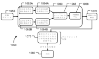
センサ130は、米国特許第10596416号に記載されているように、潜在的にハイブリッドカメラ/レーダセンサユニットを含む、カメラ(例えば、ステレオカメラ対)、レーダ装置(例えば、単一アンテナドップラーレーダ装置)、またはそれらの組み合わせを含み得る。しかし、センサ130の少なくとも1つは、カメラ120およびその関連するコンピュータ125であり、これらは通信チャネルによって接続される。図1B~図1Dは、図1Aのシステムにおいて使用され得るような、異なるセンサおよびコンピュータ構成の例を示す図である。
The
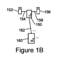
図1Bは、システムで使用される少なくとも1つの他の通信チャネルの帯域幅よりも広い第1のデータ帯域幅を有する第1の通信チャネル154、158を介して第1のコンピュータ150に接続された一対のカメラ152、156の一例を示す。例えば、第1の通信チャネル154、158は、USB(Universal Serial Bus)3.0、MIPI(Mobile Industry Processor Interface)、PCIx(Peripheral Component Interconnect eXtended)などの1つ以上の高帯域幅短距離データ通信技術が採用され得る。以下でさらに詳細に説明するように、カメラ152、156からの画像データの前処理は、1つ以上の第1のコンピュータ150においてカメラの近くで実行され得、第1のコンピュータ(単数または複数)150における前処理がデータ帯域幅を削減すると、この前処理の出力は、第1のデータ帯域幅よりも狭い第2のデータ帯域幅を有する第2の通信チャネル162を介して送信され得る。したがって、第2の通信チャネル162は、銅線イーサネットまたはワイヤレスデータ接続(例えば、WiFiおよび/または1つもしくは複数のモバイルフォン通信技術を使用する)など、1つ以上のより狭い帯域幅の、より長い距離のデータ通信技術を採用することができる。
1B shows an example of a pair of
このことは、システムが、より高い解像度のカメラ120、152、156と、これらのカメラ120、152、156からの生の画像(圧縮されていない)データに対して動作するコンピュータ125、150と共に実装されることを可能にするために、重要である。ステレオカメラ追跡またはハイブリッドカメラ/レーダ追跡のいずれを使用するかにかかわらず、より高いフレームレートを有するより高い解像度のカメラを使用することは、より高品質の3D追跡を可能にするが、データが効率的かつ効果的に処理され得る場合に限ることに留意されたい。さらに、物体追跡が非常に小さい物体に対して機能するように意図されている場合(例えば、物体が高解像度カメラ画像でも単一の画素にしか現れない場合)、従来の非可逆ビデオ圧縮技術(MPEGなど)を使用すると、小さい物体に関する貴重な情報が画像から除去される可能性があるので、物体検出は生の画像(圧縮されていない)データにアクセスする必要があり得る。
This is important to allow the system to be implemented with
これらの問題に対処するために、第1のコンピュータ(単数または複数)150は、第2の通信チャネル162を介して1つ以上の第2のコンピュータ160にセンサデータを送信するための帯域幅要件を削減するために、カメラ152、156に近い画像データに対する前処理(物体検出および任意で2D追跡を含む)を実行し得る。加えて、前処理(本文書に記載するような)は、時間および空間における測定物体位置の下流(画像キャプチャ後)仮想時刻同期を可能にし、1つ以上の第2の通信チャネル162を介して受信されたデータを使用して、3D追跡が第2のコンピュータ(単数または複数)160において実行されることを可能にする。このことにより、前処理の後、データ帯域幅が非常に狭いために長距離にわたってデータを送信することは些細なことであるので、下流処理をリモートサーバで容易に実行することが可能になる。
To address these issues, the first computer(s) 150 may perform pre-processing (including object detection and optionally 2D tracking) on image data close to the
これは、システム100が提供する柔軟性のために、システム100をセットアップするときに大きな利点を提供することができることに留意されたい。例えば、ゴルフコースの3D空間を通してゴルフボールを追跡し、ライブ送信または記録のために生成されたTV信号にゴルフボールのトレースをオーバーレイするためにシステム100を使用することができるゴルフコンペテレビ(TV)放送の場合、センサ130は、TV制作施設(3D追跡コンピュータ160が位置決めされ得る場所)から1マイル以上離れて配備され得る。(3D追跡中に識別された)ボール位置の、(ビデオデータ上へのボールの飛行経路のグラフィカル表現のトレースオーバーレイを可能にする)TVカメラによって取得されたビデオデータ内の対応する位置への変換は、既知のホモグラフィ技術を使用して実行され得ることに留意されたい。別の例として、ゴルフ娯楽施設の場合、3D追跡コンピュータ(例えば、サーバコンピュータ140、160)は、同じ施設に配置される必要はなく、このコンピュータによって実行される3D追跡(例えば、ゴルファーが位置する物理的環境のコンピュータ表現において、またはコンピュータのみに存在する仮想環境においてゴルフボールの経路を示すなど、他のデータまたはメディアを拡張するために)は、別のコンピュータに容易に転送され得る(例えば、フェイルオーバ処理)。
It should be noted that this can provide significant advantages when setting up the
種々のセンサおよびコンピュータ構成が可能である。図1Cは、各カメラ152、156が専用の第1のコンピュータ150A、150Bを有し、コンピュータ150A、150Bが、それぞれの前処理済みデータを別個の第2の通信チャネル162、164を介して第2のコンピュータ(単数または複数)160に通信する一例を示す。したがって、カメラ(または他のセンサ技術)は、第1のコンピュータリソースを共有してもよいし、または共有しなくてもよい。さらに、前処理を分割し、異なるコンピュータで実行することができる。
Various sensor and computer configurations are possible. Figure 1C shows an example in which each
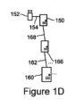
図1Dは、カメラ152が第1のデータ帯域幅を有する第1の通信チャネル154を介してコンピュータ150に結合され、第1のコンピュータ150が第3のデータ帯域幅を有する第3の通信チャネル168を介して第3のコンピュータ166に結合され、第3のコンピュータ166が第2のデータ帯域幅を有する第2の通信チャネル162を介して第2のコンピュータ160に結合される一例を示し、この場合、第2のデータ帯域幅は第1のデータ帯域幅より狭く、第3のデータ帯域幅は第1のデータ帯域幅より狭いが第2のデータ帯域幅より広い。第1のコンピュータ150は物体検出を実行し、第3のコンピュータ166は物体の2D追跡を実行し、第2のコンピュータ160は物体の仮想時刻同期および3D追跡を実行する。さらに、いくつかの実装形態では、第1のコンピュータ150は、(非常に単純な/緩い制約を使用して)2Dにおける物体検出および事前追跡を実行し、第3のコンピュータ166は、より徹底した2D追跡を実行し、第2のコンピュータ160は、物体の仮想時刻同期および3D追跡を実行する。
Figure 1D shows an example in which a
本文書の開示内容と一致する他のセンサおよびコンピュータ構成も可能である。例えば、中間の第3のコンピュータ166を使用して物体の2D追跡を実行するのではなく、第1のコンピュータ150が物体検出(2Dにおける事前追跡(非常に単純な/緩い制約を使用する)を実行するか、または物体の2D追跡を実行しない)を実行することができ、同じ第2のコンピュータ160が物体の2D追跡(2Dにおける事前追跡後のより徹底した2D追跡または全2D追跡)、仮想時刻同期、および物体の3D追跡を実行することができる。逆に、いくつかの実装形態では、1つ以上のさらなる中間コンピュータを使用することができる。例えば、システムは、4つの別個のコンピュータを使用して、物体検出、2D追跡、仮想時刻同期、および3D追跡の4つの動作のそれぞれを実行することができる。別の例として、システムは、5つの別個のコンピュータを使用して、物体検出、2Dにおける事前追跡(非常に単純な/緩い制約を使用する)、より徹底した2D追跡、仮想時刻同期、および3D追跡の5つの動作のそれぞれを実行することができる。動作のうちの少なくとも1つの動作が、第1の通信チャネルを介して少なくとも1つのカメラと通信可能に結合された第1のコンピュータで行われ、動作のうちの少なくとも1つの他の動作が、第1の通信チャネルのデータ帯域幅よりも狭いデータ帯域幅を有する第2の通信チャネルを介して第1のコンピュータと通信可能に結合された第2のコンピュータで行われるという条件で、他の構成も可能である。
Other sensor and computer configurations are possible consistent with the disclosure of this document. For example, rather than using an intermediate
種々の種類のコンピュータをシステムにおいて使用することができる。コンピュータの必須要素は、命令を実行するためのプロセッサと、命令およびデータを記憶するための1つ以上のメモリデバイスである。本明細書で使用される場合、「コンピュータ」は、サーバコンピュータ、クライアントコンピュータ、パーソナルコンピュータ、埋め込みプログラム可能回路、または専用論理回路を含み得る。図2は、第1のコンピュータ150、第2のコンピュータ160、または第3のコンピュータ166の一実装形態を表すデータ処理装置200を含むデータ処理システムの概略図である。データ処理装置200は、ネットワーク280を介して1つ以上のコンピュータ290と接続され得る。
Various types of computers can be used in the system. The essential elements of a computer are a processor for executing instructions and one or more memory devices for storing instructions and data. As used herein, a "computer" can include a server computer, a client computer, a personal computer, an embedded programmable circuit, or a special-purpose logic circuit. FIG. 2 is a schematic diagram of a data processing system including a
データ処理装置200は、アプリケーション層とオペレーティングシステムとの間に分散され得る種々のソフトウェアモジュールを含み得る。これらは、本文書に記載するように、物体検出プログラム(例えば、第1のコンピュータ150内)、2D追跡プログラム(例えば、第1のコンピュータ150および/または第3のコンピュータ166内)、仮想時刻同期プログラム(例えば、第2のコンピュータ160内)、および/または3D追跡プログラム(例えば、第2のコンピュータ160内)として動作するプログラム230を含む、実行可能および/または解釈可能なソフトウェアプログラムまたはライブラリを含み得る。使用されるソフトウェアモジュールの数は、実装形態ごとに異なり得る。また、場合によっては、例えば、2D追跡プログラム230のプログラム230は、埋め込みファームウェア内に実装され得、他の場合、例えば、時刻同期および3D追跡プログラム230のプログラム230は、1つ以上のコンピュータネットワークまたは他の適切な通信ネットワークによって接続された1つ以上のデータ処理装置上に分散されたソフトウェアモジュールとして実装され得る。
The
データ処理装置200は、1つ以上のハードウェアプロセッサ212、1つ以上の追加のデバイス214、非一時的なコンピュータ可読媒体216、通信インターフェース218、および1つ以上のユーザインターフェースデバイス220を含むハードウェアまたはファームウェアデバイスを含み得る。プロセッサ212は、非一時的なコンピュータ可読媒体216上に記憶された命令など、データ処理装置200内で実行するための命令を処理することができ、非一時的なコンピュータ可読媒体216は、追加のデバイス214のうちの1つなどのストレージデバイスを含み得る。いくつかの実装形態では、プロセッサ212は、シングルコアプロセッサまたはマルチコアプロセッサ、または2つ以上の中央処理装置(CPU)である。データ処理装置200は、その通信インターフェース218を使用して、例えばネットワーク280を介して、1つ以上のコンピュータ290と通信する。したがって、様々な実装形態では、記載されるプロセスは、シングルコアコンピューティングマシンもしくはマルチコアコンピューティングマシン上で、および/またはコンピュータクラスタ/クラウド上などで、並行してまたは連続的に実行され得る。
The
ユーザインターフェースデバイス220の例は、ディスプレイ、タッチスクリーンディスプレイ、スピーカ、マイクロフォン、触覚フィードバックデバイス、キーボード、およびマウスを含む。さらに、ユーザインターフェースデバイス(単数または複数)は、ローカルデバイス(単数または複数)220である必要はなく、データ処理装置200から離れていてもよく、例えば、1つ以上の通信ネットワーク(単数または複数)280を介してアクセス可能なユーザインターフェースデバイス(単数または複数)290であってもよい。データ処理装置200は、例えば、フロッピーディスクデバイス、ハードディスクデバイス、光ディスクデバイス、テープデバイス、およびソリッドステートメモリデバイス(例えば、RAMドライブ)のうちの1つ以上の追加のデバイス214を含み得る、非一時的なコンピュータ可読媒体216上に、本文書に記載する動作を実装する命令を記憶し得る。さらに、本文書に記載する動作を実行する命令は、1つ以上のコンピュータ290から(例えば、クラウドから)ネットワーク280を介して非一時的なコンピュータ可読媒体216にダウンロードされ得、いくつかの実装形態においては、RAMドライブは、コンピュータの電源がオンされるたびに命令がダウンロードされる揮発性メモリデバイスである。
Examples of
さらに、本開示の3D物体追跡は、本文書(および、いずれも「Motion based Pre-Processing of Two-Dimensional Image Data Prior to Three-Dimensional Object Tracking With Virtual Time Synchronization」と題された、2020年8月14日に出願された米国仮特許出願第63/065872号、および2021年8月17日に出願された米国特許出願第17/404953号)に記載されるセンサデータの前処理、2D物体追跡、および仮想時刻同期を採用することができ、したがって、本開示の3D物体追跡システムおよび技術は、一緒に実装された場合に、データ前処理、2D物体追跡、ならびに仮想時刻同期のシステムおよび技術の付随する利点を得ることができるが、いくつかの実装形態では、物体検出システムによって登録された注目物体の3次元位置を取得するためにこれらのシステムおよび技術を使用する必要はない。1つ以上の他の物体検出システムは、図7~図10Bに関連してさらに詳細に説明する3D物体追跡と共に使用され得る。 Furthermore, the 3D object tracking of the present disclosure is based on the motion-based pre-processing of two-dimensional image data prior to three-dimensional object tracking with virtual time. No. 63/065872, filed August 14, 2020, entitled "Synchronization," and U.S. Patent Application No. 17/404953, filed August 17, 2021, may be employed to pre-process sensor data, 2D object tracking, and virtual time synchronization, and thus the 3D object tracking system and techniques of the present disclosure may obtain the attendant advantages of the data pre-processing, 2D object tracking, and virtual time synchronization systems and techniques when implemented together, although in some implementations it is not necessary to use these systems and techniques to obtain the three-dimensional position of the object of interest registered by the object detection system. One or more other object detection systems may be used with the 3D object tracking, which will be described in more detail in connection with FIG. 7-FIG. 10B.
図3は、物体を検出し、2Dにおいて物体を追跡し、時刻同期のための仮想2D位置を生成し、動いている物体の3Dトラックを構築するために、異なるコンピュータで実行されるプロセスの一例を示す図である。図3のプロセスは、1つ以上の第1のコンピュータ(例えば、図1A~図1Dのコンピュータ125、150、166)で実行される前処理動作310~330と、1つ以上の第2のコンピュータ(例えば、図1A~図1Dのコンピュータ140、160)で実行される追加の処理動作360~375とを含む。前処理動作は、第2のコンピュータ(単数または複数)における追加の処理中に測定物体位置の仮想時刻同期を可能にするように、(3D追跡において使用されるデータを送信するための帯域幅要件を削減するために)ボール位置データを効果的に圧縮する物体検出および2D追跡を含み得る。
Figure 3 illustrates an example of a process performed on different computers to detect objects, track objects in 2D, generate virtual 2D positions for time synchronization, and build 3D tracks of moving objects. The process of Figure 3 includes pre-processing operations 310-330 performed on one or more first computers (e.g.,
したがって、画像フレーム300は、カメラを第1のコンピュータ(単数または複数)と結合する第1の通信チャネル305を介してカメラから(例えば、コンピュータ125、150によって)受信される(310)。この場合、画像フレーム300が受信される際に使用される第1の通信チャネル305は、第1のデータ帯域幅を有する。例えば、第1の通信チャネル305は、USB3.0、MIPI、またはPClx通信チャネル、例えば、通信チャネル(単数または複数)154、158であり得る。カメラとコンピュータとの間の帯域幅要件は、1ギガビット/秒(Gbps)を容易に超える可能性があり、例えば、60フレーム/秒(FPS)および12ビット/画素で動作する12メガピクセル(MP)カメラは、8Gbpsを超える帯域幅を必要とすることに留意されたい。
Thus, the
さらに、組み合わせて使用される複数のこのようなカメラは、10~100Gbpsの全帯域幅を必要とする場合があり、これは、イーサネット通信ハードウェアにさえ深刻な負担をかけることになる。さらに、ステレオ装置(例えば、図1Bのステレオカメラ152、156)は、カメラ間、またはカメラとサーバルームもしくはクラウドベースのコンピューティングなどのコンピュータインフラストラクチャとの間にかなりの距離を必要とすることがあり、長いケーブルおよび/またはインターネットを介した通信が必要とされる場合、高帯域幅通信をさらに困難にする。上述したように、MPEG技術などの従来のビデオ圧縮技術は、特に、小さな物体(例えば、遠くのゴルフボール)が追跡される場合に、追跡物体が従来のビデオ圧縮によって除去されるリスクがあるので、帯域幅を削減する適切な方法ではない場合がある。したがって、高帯域幅通信チャネル305が(1つ以上のカメラからのビデオフレームのために)使用されることにより、高解像度、高ビット深度、および/または非圧縮画像データが物体検出プロセスへの入力として受信される(310)ことが可能になる。
Moreover, multiple such cameras used in combination may require a total bandwidth of 10-100 Gbps, which would put a serious strain on even Ethernet communication hardware. Furthermore, stereo equipment (e.g.,
受信された画像フレームにおいて(例えば、コンピュータ125、150によって)注目位置が識別される(315)。例えば、これは、画像差分技術を使用して、以前の画像フレームから閾値量を超えて変化する1つ以上の画像データ値を有する画像フレーム内の各位置を識別することを伴い得る。さらに、他の手法も可能である。例えば、プロセスは、特定の輝度または色(例えば、ゴルフボールでは白)の画素群を探し、追跡物体の形状に一致する形状(例えば、丸いゴルフボールを見つけるための丸い形状または少なくとも楕円形状)を探し、および/またはテンプレートマッチングを使用して画像内の物体(例えば、ゴルフボール)を探索することができる。
Locations of interest are identified (315) in the received image frames (e.g., by
さらに、1つの画像フレームから別の画像フレームへ閾値量を超えて変化する1つ以上の画像データ値を有する位置を探すことは、画像差分を適用して、閾値量を超えて変化する画素または画素群を発見することを含み得る。例えば、画像差分を適用して、各画像において特定の閾値を超えて変化する画素を発見することができ、互いに隣接するそのような変化画素群を、例えば、既知の連結成分ラベリング(CCL)技術および/または連結成分分析(CCA)技術を使用して発見することができる。物体検出基準を満たすそのような画素群(および潜在的に単一画素も)は、「ブロブ」と呼ばれ、そのような各ブロブの位置およびサイズは、リストに記憶され得、各画像内の全てのブロブのリストは、2D追跡コンポーネントに送信され得る。画像を物体位置(またはブロブ)のリストに変換することは、帯域幅削減効果を有する。場合によっては、この動作の帯域幅削減は、10:1以上であり得る。しかし、本文書に記載するように、さらなる帯域幅削減を達成することができ、このことは、小さな物体が追跡される場合に大きな利益をもたらし得る。 Furthermore, finding locations having one or more image data values that change from one image frame to another by more than a threshold amount may include applying image differencing to find pixels or groups of pixels that change by more than a threshold amount. For example, image differencing may be applied to find pixels in each image that change by more than a certain threshold, and groups of such changing pixels that are adjacent to each other may be found, for example, using known connected component labeling (CCL) and/or connected component analysis (CCA) techniques. Such groups of pixels (and potentially even single pixels) that meet the object detection criteria may be called "blobs," and the location and size of each such blob may be stored in a list, and the list of all blobs in each image may be sent to the 2D tracking component. Converting the image to a list of object locations (or blobs) has a bandwidth reduction effect. In some cases, the bandwidth reduction of this operation may be 10:1 or more. However, as described herein, further bandwidth reductions may be achieved, which may be of great benefit when small objects are tracked.
小さな物体の追跡の場合、物体の特徴に基づいて小さな物体(場合によっては画像内の単一画素)を識別することが困難であるため、誤検出の重大な問題がある。したがって、(カメラ画像内の特定の位置で注目物体を検出するために)識別すること(315)は、多数の偽陽性を許容しながら、0個の偽陰性を優先するために低い閾値を用いて実装され得る。この手法は、物体追跡における偽陽性が好まれないことが多く、したがって、偽陽性の最小化と偽陰性の最小化との競合を設定するという点で、一般に直観に反した手法であることを諒解されたい。しかし、下流処理が大量の偽陽性を処理するように設計されているので、物体追跡に対する本発明の手法は偽陽性に容易に対処するものである。だが、物体検出は多くの偽陽性を許容するように設計されているので、画像データ内のまさにノイズである多くの「物体」を含む、より多くの物体が各画像フレーム300内で識別され(315)、したがって、画像を物体のリストに変換する帯域幅削減効果を部分的に相殺する。
For small object tracking, there is a significant problem of false positives due to the difficulty of identifying small objects (possibly even a single pixel in an image) based on the object's features. Thus, identifying (315) (to detect an object of interest at a particular location in a camera image) may be implemented with a low threshold to favor zero false negatives while tolerating a large number of false positives. It should be appreciated that this approach is generally counter-intuitive in that false positives in object tracking are often not favored, thus setting up a competition between minimizing false positives and minimizing false negatives. However, our approach to object tracking easily handles false positives because downstream processing is designed to handle a large number of false positives. Yet, because object detection is designed to tolerate many false positives, many more objects are identified (315) in each
画像フレームにおいて識別された位置のシーケンスが(例えば、コンピュータ125、150、160、166によって)発見される(320)。図3(および他の図)に示されるプロセスは、理解を容易にするために順次動作として示されているが、実際には、動作は、例えば、ハードウェアおよび/もしくはオペレーティングシステムベースのマルチタスクを使用して、ならびに/またはパイプライン処理技術を使用して、並行してまたは同時に行われ得ることに留意されたい。パイプライン処理は、同時処理のために使用され得、例えば、物体識別(315)は、下流コンポーネントが最初に終了するのを待つ必要なく、フレームnを2D追跡(320)にハンドオフした直後に、利用可能であれば、フレームn+1の処理を開始することができる。したがって、各コンピュータ上で実行されるプロセスが順次プロセスとして説明される場合、すなわち、物体識別プロセス、2D追跡プロセス(単数または複数)、ならびに仮想時刻同期および3D追跡プロセス(単数または複数)が順次発生する場合を除いて、各々の物体識別および2D追跡処理ステップは下流コンポーネントに送信されるデータの帯域幅を削減するので、図面に関連して本文書で提示される開示内容は、図面に示されるように、動作を順次実行することに限定されない。
A sequence of identified locations in the image frames is found (320) (e.g., by
発見された(320)シーケンスの各々は、カメラからの少なくとも3つの画像フレームにおいて識別された位置について動き基準を満たす。いくつかの実装形態では、基準は、4つ以上のフレームに関して測定され、および/または1つもしくは複数の基準が使用される(例えば、以下で説明する木開始基準)。一般に、2D追跡は、重力、バウンド、風、空気抵抗、または摩擦以外の力に影響されない、ニュートン運動における物体の移動と一致する物体移動を示す3つ以上のフレームにわたる物体(またはブロブ)のシーケンスを発見することを目指すものである。 Each of the discovered (320) sequences satisfies a motion criterion for the identified location in at least three image frames from the camera. In some implementations, the criterion is measured for four or more frames and/or one or more criteria are used (e.g., the tree initiation criterion described below). In general, 2D tracking aims to find sequences of objects (or blobs) over three or more frames that exhibit object motion consistent with object motion in Newtonian motion, unaffected by forces other than gravity, bouncing, wind, air resistance, or friction.
この物体移動の基準は、定義済みの値の範囲内にある各次元(画像内のxおよびy)における変位、速度、および/または加速度を含むように定義され得る。この値の範囲は、2Dカメラによって描写されるような、動いている物体(例えば、飛んでいるゴルフボール)の2D動きおよび加速度が、指定された境界の十分内側にある一方で、より痙攣的な動きが却下される(追跡物体を跳ね返す可能性がある既知の物体が存在しない限り)ように設定される。さらに、より大型のシステムは、実際の追跡物体(例えば、ゴルフショット)を構成するものをより細かい粒度でフィルタリングすることができる、下流処理において二次追跡ステップを採用するので、発見すること(320)は、ティーエリア112から打たれた後のゴルフボールの動きなどの実際の物体の動きのみを許可する完全な(または完全に近い)フィルタである必要はない。
This object movement criteria may be defined to include displacement, velocity, and/or acceleration in each dimension (x and y in the image) within a predefined range of values. This range of values is set such that the 2D motion and acceleration of a moving object (e.g., a flying golf ball) as depicted by a 2D camera is well inside the specified boundaries, while more jerky motion is rejected (unless there is a known object that may bounce the tracked object). Furthermore, larger systems employ a secondary tracking step in downstream processing that can filter with finer granularity what constitutes an actual tracked object (e.g., a golf shot), so the finding (320) does not need to be a perfect (or near-perfect) filter that only allows in actual object motion, such as the motion of a golf ball after being hit from the
むしろ、発見すること(320)において行われるフィルタリングを意図的に完全ではないフィルタリングにすることにより、動いている物体以外の物体が、発見されたシーケンス(注目物体として誤って識別され(315)、次いで誤って発見されて(320)シーケンスが形成されたノイズの潜在的なシーケンスを含む)に含まれるようにすることができる。言い換えれば、発見すること(320)は、偽陽性を増加させて偽陰性を最小限に抑える緩いフィルタを実装することができ、例えば、動いている全てのまたは全てに近いゴルフボールが、発見すること(320)において有効なシーケンスを形成するものとして許可される。 Rather, the filtering performed in finding (320) may be intentionally non-exhaustive, allowing objects other than the moving object to be included in the found sequence (including potential sequences of noise that may have been erroneously identified (315) as an object of interest and then erroneously found (320) to form the sequence). In other words, finding (320) may implement a loose filter that increases false positives and minimizes false negatives, e.g., all or nearly all moving golf balls are permitted to form valid sequences in finding (320).
このより緩い(疑いの範囲にとどめる)手法は、所望の物体(例えば、ゴルフボール)を不要の物体(例えば、非ゴルフボール)と区別する際に完全である必要がないことを理解した上で、はるかに単純な追跡アルゴリズムを(320)において使用することができることを意味する。追跡を定義する一連の規則は、最小限に低減され得、(非ゴルフボールを通過させる場合のように)2D追跡によって行われる誤りはいずれも、下流コンポーネントおよび処理によって除去され得る。各々が1つの起点および1つの終点を有する軌道経路全体を放出する代わりに、発見された(320)シーケンスは、「根付き木」で表され得、この場合、各頂点(木内のノード)は、観測ブロブ(x、y、および時間t)であり、各エッジは、動きが追跡されている物体の位置間の可能な移動である。図4Aに関連してさらに詳細に説明するように、各々の枝は、木の全深さなどのいくつかのメタデータをさらに有し得る。 This looser (below the doubt) approach means that a much simpler tracking algorithm can be used in (320), with the understanding that it does not need to be perfect in distinguishing desired objects (e.g., golf balls) from unwanted objects (e.g., non-golf balls). The set of rules that define the tracking can be reduced to a minimum, and any errors made by 2D tracking (such as passing non-golf balls) can be removed by downstream components and processing. Instead of emitting entire trajectory paths, each with one start and one end, the discovered (320) sequence can be represented as a "rooted tree", where each vertex (node in the tree) is an observation blob (x, y, and time t) and each edge is a possible transition between the positions of the object whose motion is being tracked. As will be described in more detail in connection with FIG. 4A, each branch may further have some metadata, such as the total depth of the tree.
しかしながら、このより緩い(疑いの範囲にとどめる/低い閾値)手法を用いても、物体検出を見逃すことが依然として起こり得る。したがって、ダミー観測を使用して、画像データ内にあるはずだが識別されていない物体を説明することができる。いくつかの実装形態では、経路を拡張することができる十分に良好なブロブが発見されない場合、2Dトラッカは、予測位置におけるダミー観測を追加することができる。ダミー観測は、有意なペナルティスコアを伴って実装され得、いくつかの実装形態では、ダミー観測は、グラフがすでに特定の深さでない限り、許可されないことになる。枝がどれだけのペナルティを有することができるかについて制限があるので、実際には、経路がどれくらいの数のダミー観測を有することができるかについて制限がある。 However, even with this looser (below doubt/low threshold) approach, it is still possible to miss an object detection. Thus, dummy observations can be used to account for objects that should be in the image data but are not identified. In some implementations, if a good enough blob is not found that the path can be extended to, the 2D tracker can add a dummy observation at the predicted location. Dummy observations can be implemented with a significant penalty score, and in some implementations, dummy observations will not be allowed unless the graph is already at a certain depth. Since there is a limit on how much penalty a branch can have, in practice there is a limit on how many dummy observations a path can have.
上述したように、発見すること(320)は、注目位置から根付き木を形成することを伴い得、各根付き木は、木の根である根ノードを有する連結非周期グラフであり、連結非周期グラフの全てのエッジは、直接的または間接的に根から生じる。図4Aは、根付き木を形成することによって動き基準を満たす物体位置のシーケンスを発見するプロセスの一例を示す。(400)において、画像フレームについて識別された次の位置集合が処理のために取得され、注目位置が現在のフレームについての集合内に残っている(405)間、この処理は継続する。例えば、ブロブのフレームが処理されるときに、新しいフレーム内の全てのブロブは、動き基準によって定義されるように、この枝内のポイントが所望の動きのようにどれだけ見えるかに応じて、ブロブがその経路の可能な連続であり得るかどうかを見るために、以前のフレームの処理中に追加された全ての木ノードに一致され得る。 As mentioned above, finding (320) may involve forming a rooted tree from the positions of interest, where each rooted tree is a connected acyclic graph with a root node that is the root of the tree, and all edges of the connected acyclic graph originate directly or indirectly from the root. FIG. 4A shows an example of a process for finding a sequence of object positions that meet the motion criteria by forming a rooted tree. At (400), the next set of positions identified for the image frame is obtained for processing, and this process continues while the position of interest remains in the set for the current frame (405). For example, when a frame of blobs is processed, every blob in the new frame may be matched to every tree node added during the processing of the previous frame to see if the blob could be a possible continuation of its path, depending on how much the points in this branch look like the desired motion, as defined by the motion criteria.
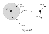
次の注目位置が集合から検索され(410)、この注目位置が木開始基準を満たすかどうかを判定するためにチェックが行われる(415)。注目位置が木開始基準を満たす場合、新しい木の根ノードが、この注目位置を使用して確立される(420)。例えば、注目位置における画像データ値が最小物体サイズより大きい場合、これは、ボールがカメラに近く、新しい木を確立すべきであることを示すために使用され得る。図4Bは、この視覚的な例を示しており、6つのブロブ460が観測されるが、これらのブロブ460のうちの4つのみが、新しい根ノード465を確立するために使用されるのに十分な大きさである。1つのブロブ観測をいくつかの木に追加することができ、全ての観測ブロブは、理論的には、新しい物体観測の開始であり得ることに留意されたい。これは、ノイズの多い環境における組み合わせ爆発につながる可能性があり、したがって、いくつかの実装形態では、新しい木を確立する前に、何らかの追加の制約(最小ブロブサイズ制約など)が課せられる。
The next attention location is retrieved from the set (410) and a check is made to determine whether this attention location meets the tree initiation criteria (415). If the attention location meets the tree initiation criteria, the root node of a new tree is established using this attention location (420). For example, if the image data value at the attention location is larger than the minimum object size, this can be used to indicate that the ball is close to the camera and a new tree should be established. FIG. 4B shows a visual example of this, where six
この例では、特定の最小サイズよりも大きい全てのブロブが、深さ0の新しい木に昇格され、最小サイズ限界は、カメラ解像度および着信ビデオのノイズレベルに基づいて設定され得る。例えば、基準は、新しい木を確立するためにブロブが少なくとも2画素(単一画素だけではない)でなければならないということであり得る。真にランダムなノイズは、画素に個々に影響を及ぼし、画像においてより大きなクラスタを生成することは非常に稀であることに留意されたい。組み合わせ爆発を回避する他の手法も可能である。例えば、ブロブ生成(すなわち、位置識別)プロセスにおけるノイズ閾値を適応的に調整することができる。
In this example, all blobs larger than a certain minimum size are promoted to a new tree of
さらに、経路がエクスポートされるのに必要な最小木深さを増加させることができ、ランダムノイズシーケンスが偶然により長いシーケンスを構築することは稀であるので、エクスポートされるデータの量が確実に制限される。制約が非常に緩いため、深さ0および深さ1を伴う多くのグラフが生成されるが、予測がより良好であるため、これらのグラフの大部分は決して深さ2に到達せず、さらに深さ3に到達するグラフはより少なくなる。したがって、木または枝は、追加され得るノードがそれ以上ない場合に破棄されるので、統計は、本開示のシステムおよび技術の利益のために有効である。
Furthermore, the minimum tree depth required for a path to be exported can be increased, ensuring that the amount of data exported is limited since it is rare for a random noise sequence to build a longer sequence by chance. Because the constraint is very loose, many graphs with
さらに、カメラが物体の打ち出しエリアの方に向き直った状態でターゲットの近くに配置される場合、すなわち、飛来してくる物体を検出する場合、画像の異なる部分に異なるサイズ閾値を適用することができる。例えば、離れたボールが見つかる部分(例えば、長方形)では最小サイズの1画素を使用することができ、他の部分では最小サイズの2画素を使用することができる。したがって、可能な物体経路の木を形成するために使用される基準は、打ち出しエリアに対するカメラの位置に基づいて決定され得る。 Furthermore, when the camera is placed near the target facing the object launch area, i.e., to detect incoming objects, different size thresholds can be applied to different parts of the image. For example, a minimum size of 1 pixel can be used in parts where the distant ball is found (e.g., rectangular), and a minimum size of 2 pixels can be used in other parts. Thus, the criteria used to form the tree of possible object paths can be determined based on the position of the camera relative to the launch area.
例えば、ある程度平坦な地面が推測され得、カメラ位置および照準が既知である場合、地面の「水平線」の下の全てのボール検出は、ボールが存在し得る最大距離(したがって、最小サイズ)の推定値に対して「サニティー」チェックされ得る。カメラからボール検出までの光線は、ある距離Dにおける地面と交差する。ボールは距離Dまたはそれより近くに位置しなければならず、そうでなければボールは地下にあることになる。「水平線」より上のランダムなボール検出については、地面との交差がないので、単純な距離ヒューリスティックはない。しかしながら、3D空間(例えば、競技場)の限界についての知識がある場合、物体が3D注目領域内になければならないことを考慮して、何らかの一般的なおよび/または角度依存の最大距離/最小物体サイズ制約が使用され得る。 For example, if a reasonably flat ground can be assumed and the camera position and aiming are known, then all ball detections below the ground "horizon" can be "sanity" checked against an estimate of the maximum distance (and therefore minimum size) at which the ball can be. The ray from the camera to the ball detection intersects the ground at some distance D. The ball must be located at or near distance D, otherwise it is underground. For random ball detections above the "horizon", there is no simple distance heuristic since there is no intersection with the ground. However, if there is knowledge of the limits of the 3D space (e.g., a playing field), some general and/or angle-dependent maximum distance/minimum object size constraints can be used, taking into account that objects must be within the 3D region of interest.
図4Aに戻ると、現在の注目位置が、以前の画像フレーム内で識別された位置について確立された根ノードの距離閾値内にあるかどうかを判定するためにチェック(425)が行われる。注目位置が距離閾値内にあれば、注目位置は、第1の深さサブノードとして、この木の根ノードの下に追加される(430)。木が1つの頂点のみから構成される場合(深さ=0)、その経路の速度を推定する方法はまだないので、頂点から妥当な距離内にある任意のブロブにマッチングされる必要があることに留意されたい。図4Cは、図4Bに続く、この視覚的な一例を示す。4つの観測ブロブ470のうち2つのブロブのみが、以前のフレームから根ノード474の距離限界472内にある。したがって、ブロブ470のうちの2つのみが、第1の深さサブノード476として根付き木に追加される。いくつかの実装形態では、距離限界は、着信センサの解像度およびフレームレート、ならびに追跡されている物体の最大予想速度(カメラの照準方向に垂直)に依存する。ゴルフボールの場合のように、追跡されている物体のサイズが事前に分かっている場合、距離限界/閾値472を決定する際に、これを考慮に入れることができる。さらに、大きいブロブは小さいブロブよりもカメラに近いと推定することができ、つまり、(追跡されている物体の予想される方向に対するカメラの配置に応じて、以前のフレームまたは現在のフレームのいずれかにおいて)より大きいブロブが存在する場合、フレーム間のより大きい移動が許容され得る。
Returning to FIG. 4A, a check (425) is made to determine whether the current location of interest is within the root node's distance threshold established for a location identified in the previous image frame. If the location of interest is within the distance threshold, the location of interest is added (430) as a first depth subnode under the root node of this tree. Note that if the tree consists of only one vertex (depth=0), there is still no way to estimate the speed of the path, so any blobs that are within a reasonable distance from the vertex need to be matched. FIG. 4C shows a visual example of this, continuing from FIG. 4B. Only two of the four observed
しかしながら、ブロブを深さ1以上の頂点に一致させる場合、経路内の次のポイントがどこにあるべきかを予測することが可能である。いくつかの実装形態では、次のブロブの予想される領域は、速度が最後のフレーム以降同じであると推定することによって計算される。図4Dは、この視覚的な一例を示す。根ノード480の位置および第1の深さサブノード482の位置に加えて、カメラの既知のフレームレートに基づいて、予測位置484が計算される。次いで、予測位置484の周りの探索エリア486(または領域)が、木に追加するブロブを探す際に使用するために決定される。距離限界/閾値472を決定するために上記で示された詳細と同様に、予測位置484の周りのエリア/領域486のサイズは、カメラの解像度と、追跡されている物体の最大予想速度(カメラの照準方向に垂直)とに基づいて決定され得、物体の最大予想速度は、物体の既知のサイズおよび異なる画像フレーム内のブロブのサイズに従って調整される可能性がある。さらに、いくつかの実装形態では、例えば、グラフの次数が十分に大きい場合、予測を作成する際にカルマンフィルタを使用することができる。
However, if we match a blob to a vertex at
予測位置に十分に近い任意のブロブは、頂点に変換され、木に追加され得る。したがって、図4Dに示すように、1つのブロブが予測位置484の領域486内にあり、したがって、このブロブは新しいサブノード488として追加される。加えて、いくつかの実装形態では、ペナルティは、木の枝上で累積され得、ペナルティは、枝をランク付けするために使用されるスコアに加算され、これは、エクスポートする最良枝を決定する際に役立ち得る。さらに、いくつかの実装形態では、ブロブの位置が予想座標から逸脱するほど、この枝に付与されるペナルティが高くなり得る。 Any blob that is close enough to the predicted location may be converted into a vertex and added to the tree. Thus, as shown in FIG. 4D, one blob is within region 486 of predicted location 484, and therefore this blob is added as a new subnode 488. Additionally, in some implementations, penalties may be accumulated on the branches of the tree, and the penalties are added to a score used to rank the branches, which may aid in determining the best branch to export. Furthermore, in some implementations, the further the blob's location deviates from the expected coordinates, the higher the penalty that may be assigned to this branch.
いくつかの実装形態では、木の枝上で累積されたペナルティは、許容されるペナルティの大きさを制限するために、およびいつ枝を破棄すべきかを決定するために使用され得る。前者のケースでは、枝が既に高いペナルティを有する場合、拡張された枝が限界を超えるような新しいノードを追加することは許されない。ペナルティが予測位置と実際の位置との間の不一致から計算される場合、これは本質的に加速度が限界内にあることを確実にする方法である。そうでない場合、ペナルティは高くなりすぎる。後者のケースでは、最後の3つのブロブを共有するいくつかの枝がある場合に、最も深く、最も小さいペナルティを有する枝を保持することができ、他の枝を破棄することができる。このタイプのペナルティベースの仮説追跡は、2D追跡に加えて、(例えば、図7~図10Bに関連してさらに詳細に説明するような)3D追跡に適用され得ることに留意されたい。 In some implementations, the penalty accumulated on a tree branch may be used to limit the magnitude of the penalty allowed and to determine when a branch should be discarded. In the former case, if a branch already has a high penalty, adding a new node that would cause the extended branch to exceed the limit is not allowed. If the penalty is calculated from the discrepancy between the predicted and actual positions, this is essentially a way to ensure that the acceleration is within the limit; otherwise, the penalty becomes too high. In the latter case, if there are several branches that share the last three blobs, the branch that is deepest and has the smallest penalty can be kept and the other branches can be discarded. Note that this type of penalty-based hypothesis tracking can be applied to 3D tracking (e.g., as described in more detail in connection with Figures 7-10B) in addition to 2D tracking.
図4Aに戻ると、チェック(435)は、現在の注目位置が、確立された木の親サブノードに使用される位置の推定速度を使用して決定された領域内にあるかどうかを決定するために行われる。現在の注目位置が領域内にある場合、注目位置は、図4Dに関連して上述したように、親サブノードの下に、第2のまたはより深い深さのサブノードとしてこの木に追加される(440)。加えて、いくつかの実装形態では、木の深さが増加すると、より高度な予測アルゴリズムが、より良好な予測を得るために使用され得る。枝内の直近のノードを2次または3次の多項式関数にフィッティングさせることによって、次のポイントがどこにあるかの良好な予測が得られ、加速度の明らかに不合理な変化を有する経路が破棄され得る。さらに、いくつかの実装形態では、観測をカルマンフィルタに提供することができ、カルマンフィルタのモデルを使用して新しい予測を生成することができる。 Returning to FIG. 4A, a check (435) is made to determine whether the current attention position is within the region determined using the estimated velocity of the position used for the parent subnode of the established tree. If the current attention position is within the region, the attention position is added to this tree as a subnode of a second or greater depth under the parent subnode (440), as described above in connection with FIG. 4D. Additionally, in some implementations, as the depth of the tree increases, more advanced prediction algorithms can be used to obtain better predictions. By fitting the immediate nodes in the branches to a second or third order polynomial function, a good prediction of where the next point will be can be obtained, and paths with clearly unreasonable changes in acceleration can be discarded. Additionally, in some implementations, the observations can be provided to a Kalman filter, and a model of the Kalman filter can be used to generate a new prediction.
また、単一の画像フレーム内の同じ注目位置を、画像フレームを通して潜在的な物体経路のトラックを維持している、ならびに新しい木の新しい根ノードを確立するために潜在的に使用されている2つ以上の根付き木に(第1の深さまたはより深い深さの)それぞれのサブノードとして追加することができることに留意されたい。さらに、単一の画像フレーム内の同じ注目位置を、木内のそれぞれの親ノードに戻る2つ以上のリンケージを有する木内のサブノードとして追加することができ、この木は、どのリンケージが根ノードに戻るかに応じて異なる深さを有する同じサブノードを含む。 Note also that the same location of interest in a single image frame can be added as a respective subnode (at a first depth or at a greater depth) to two or more rooted trees that are keeping track of potential object paths through the image frames as well as potentially being used to establish a new root node for a new tree. Furthermore, the same location of interest in a single image frame can be added as a subnode in a tree with two or more linkages back to respective parent nodes in the tree, and the tree will contain the same subnode with different depths depending on which linkage goes back to the root node.
したがって、多くの誤った経路が生成され、下流処理がこれらの誤った経路をフィルタ除去することができるとしても、潜在的な経路がいつ出力されるかについては依然として制限があるはずである。いくつかの実装形態では、シーケンスを表す根付き木が所定の木深さを超える(445)まで、シーケンスは出力のために考慮されない。したがって、識別された位置のシーケンスは、所与の実装形態に対して指定されるように、または1つもしくは複数の要因に基づいてオンザフライで決定されるように、シーケンスの木深さが所定の木深さを超えている(445)かに基づいて、シーケンスが出力のために確認される(450)まで出力されない。 Thus, even if many erroneous paths are generated and downstream processing can filter out these erroneous paths, there may still be limitations on when potential paths are output. In some implementations, a sequence is not considered for output until the rooted tree representing the sequence exceeds a predetermined tree depth (445). Thus, a sequence of identified locations is not output until the sequence is confirmed for output (450) based on whether the tree depth of the sequence exceeds a predetermined tree depth (445), as specified for a given implementation or determined on the fly based on one or more factors.
所定の木深さを有する根付き木の一部分のみが、識別された位置のシーケンスとしての出力のために確認される(450)必要があることに留意されたい。これは、根付き木において誤った経路を生成するノイズが、第1のコンピュータでの前処理段階における2D追跡から第2のコンピュータでの後処理段階に伝搬されるのを防止するのに役立つ。また、最小木深さ閾値は、一般に、環境と、物体の3Dトラックを生成するための許容可能な遅延とに依存する。いくつかの実装形態では、シーケンスの根付き木は、シーケンスが出力のために確認される(450)前に、2よりも深い木深さを有しなければならない。いくつかの実装形態では、木は、シーケンスが出力のために確認される(450)前に、3、4、5、6、または7よりも深い深さを有しなければならない。 Note that only a portion of the rooted tree with a given tree depth needs to be checked (450) for output as a sequence of identified positions. This helps to prevent noise that would generate erroneous paths in the rooted tree from propagating from the 2D tracking in the pre-processing stage at the first computer to the post-processing stage at the second computer. Also, the minimum tree depth threshold generally depends on the environment and the tolerable delay for generating 3D tracks of objects. In some implementations, the rooted tree of a sequence must have a tree depth deeper than 2 before the sequence is checked (450) for output. In some implementations, the tree must have a depth deeper than 3, 4, 5, 6, or 7 before the sequence is checked (450) for output.
例えば、いくつかの実装形態では、木の頂点(ブロブ/位置に対応する)は、木内の特定の深さ(D)にある場合、または木内の特定の深さ(D)を有する子ノードによりエクスポートされる子ノードを有する場合にのみエクスポートされる。D=5の頂点は、それ自体と根との間に5つのエッジを有する。これは、ブロブが十分に長い枝の一部であるかどうかを事前に知ることができない場合が多いので、出力が同じフレーム数Dだけ遅延される可能性があることを意味する。エクスポートされるブロブのみが可能な経路を構成するブロブであるため、説明したフィルタリング(木のノードのエクスポートを制限することによる)は、物体候補を通信するのに必要な帯域幅を劇的に削減することが証明され得る。以下の表は、必要とされる最小枝深さに基づくゴルフ用途のための帯域幅の削減の一例を示す。

この表から分かるように、全ての注目ブロブ/位置の大部分は、いずれの経路によっても接続されないか、または十分な深さの経路によって接続されないかのいずれかであり、したがって、ほとんどの注目ブロブ/位置は、前処理段階において行われる効果的なフィルタリングによって却下される。図3に戻ると、325において、シーケンスについてのデータが出力の準備ができているか否かを決定するために、すなわち、上述したように、所定の木深さよりも深い木深さを有する少なくとも1つのノードを含む木内のノードの任意のシーケンスについて、そのシーケンスのノードは出力の準備ができているか否かを決定するためにチェックが行われる。出力の準備ができている場合、位置の1つ以上のシーケンスについての出力データは、1つ以上の第2のコンピュータ(例えば、コンピュータ140、160)に(例えば、コンピュータ125、150、166によって)送信される(330)。しかしながら、いくつかの実装形態では、識別された(315)位置は、第1のコンピュータから(例えば、コンピュータ125、150によって)第2のコンピュータ(例えば、コンピュータ140、160、166)に送信され、第2のコンピュータは、画像フレーム内で識別された位置のシーケンスを発見し(320)、次いで、シーケンスデータを同じコンピュータ上または異なるコンピュータ上の別のプロセスに出力する。いずれの場合も、シーケンス出力データは、少なくとも、各シーケンス内の各位置について、タイムスタンプを有する特定の画像フレーム内の位置の2次元位置を含み、タイムスタンプは、第2のコンピュータでの仮想同期に必要である。
As can be seen from this table, the majority of all blobs/locations of interest are either not connected by any path or are not connected by paths of sufficient depth, and therefore most blobs/locations of interest are rejected by the effective filtering performed in the pre-processing stage. Returning to FIG. 3, at 325, a check is made to determine whether data for a sequence is ready for output, i.e., for any sequence of nodes in the tree that includes at least one node with a tree depth greater than a predetermined tree depth, as described above, to determine whether the nodes of that sequence are ready for output. If so, the output data for one or more sequences of locations is sent (330) (e.g., by
3D追跡の基礎の1つは三角測量である。しかしながら、2つのカメラで見られる物体の位置の三角測量では、同じ時間インスタンスからの観測がそろっている必要がある。これを達成する一般的な方法は、全てのカメラに共通の同期トリガ信号(例えば、ケーブルを介して送信される)を使用することである。しかし、この方法は、カメラが同じキャプチャフレームレートを有する場合にのみ有効である。いくつかの構成では、2つのカメラが同期している(タンデム方式で画像キャプチャをトリガする)ことを保証することは困難または不可能であり、ひいては、異なるカメラからの観測の三角測量が困難または不可能になる。この問題を解決するために、データキャプチャの時点でカメラ画像を他のセンサ(単数または複数)と実際に同期させることを試みるのではなく、タイムスタンプ情報(2D経路によって表される移動に関する情報と組み合わせて)が、第2のコンピュータにおける仮想同期のために使用される。 One of the cornerstones of 3D tracking is triangulation. However, triangulation of the position of an object seen by two cameras requires that the observations from the same time instance are aligned. A common way to achieve this is to use a common synchronization trigger signal (e.g., transmitted over a cable) for all cameras. However, this method is only effective if the cameras have the same capture frame rate. In some configurations, it is difficult or impossible to ensure that the two cameras are synchronized (triggering image capture in tandem), which in turn makes triangulation of observations from different cameras difficult or impossible. To solve this problem, rather than trying to actually synchronize the camera images with the other sensor(s) at the time of data capture, timestamp information (combined with information about the movement represented by the 2D path) is used for virtual synchronization in the second computer.
さらに、本文書に記載するシステムおよび技術は、グローバルシャッタカメラおよびローリングシャッタカメラの両方で使用可能である。ローリングシャッタとは、カメラ画像内の各行のキャプチャのタイミングが異なることを意味する。したがって、物体がセンサによって撮像されるときに、物体の位置を決定することができるが、測定時間は、画像内のどこに物体が見つかるかに依存する。いくつかの実装形態では、上端画像行と下端画像行との間に約20ミリ秒の時間差があり得る。このことはまた、両方のカメラにおける同時測定の要件が満たされない可能性があるので、三角測量の問題を生じさせる。この問題を解決するために、フレームのタイムスタンプに加えて、フレーム内の「位置」の特定の時間オフセットの相対時間を考慮に入れることによって、ローリングシャッタ情報も考慮に入れられ、そのことにより、ローリングシャッタカメラからの測定物体位置も、後処理段階の間に第2のコンピュータにおいて高品質三角測量のために使用可能になる。グローバルシャッタキャプチャの場合、このオフセットは常に0である。 Furthermore, the systems and techniques described in this document can be used with both global and rolling shutter cameras. Rolling shutter means that the timing of the capture of each row in the camera image is different. Thus, the position of the object can be determined as it is imaged by the sensor, but the measurement time depends on where the object is found in the image. In some implementations, there may be a time difference of about 20 ms between the top and bottom image rows. This also creates a problem for triangulation, since the requirement of simultaneous measurement in both cameras may not be met. To solve this problem, the rolling shutter information is also taken into account by taking into account the relative time of a specific time offset of the "position" in the frame in addition to the frame timestamp, so that the measured object position from the rolling shutter camera is also available for high quality triangulation in the second computer during the post-processing stage. For global shutter capture, this offset is always 0.
表1に関連して上述したように、トラックを最小経路長(最小木深さ)要件に適合させるために、いくつかのデータフレームが必要とされる場合があるので、全てのブロブに遅延を導入することと、すでに適合されたブロブが認識されるとすぐにそれらを通信することを可能にするより複雑なプロトコルを実装することとの間にトレードオフがある。したがって、いくつかの実装形態では、送信すること(330)は、フレームおよびブロブデータの両方の遅延ディスパッチを伴い、いくつかの実装形態では、送信すること(330)は、フレームおよびブロブデータの増分ディスパッチを伴う。 As discussed above in connection with Table 1, since several frames of data may be required to make a track conform to the minimum path length (minimum tree depth) requirement, there is a tradeoff between introducing a delay for every blob and implementing a more complex protocol that allows already conformed blobs to be communicated as soon as they are recognized. Thus, in some implementations, sending (330) involves a delayed dispatch of both frame and blob data, and in some implementations, sending (330) involves an incremental dispatch of frame and blob data.
遅延ディスパッチの場合、送信すること(330)は、所与の画像フレームについて識別されたさらなる注目位置が、後続の画像フレームにおいて識別された注目位置に基づいてシーケンスのいずれにも含まれなくなるまで、所与の画像フレームおよびシーケンスのうちの1つ以上において発見されたその注目位置についてのデータの出力を遅延させることを伴う。したがって、フレームに対するノードのエクスポートは、処理された後続フレームの数が、現在のフレーム内の任意のより多くのブロブについて到達している定義済みの木深さを除外するときに行われ得る。言い換えれば、フレームの送信は、フレーム内で識別されたさらなるブロブが、必要とされる最小木深さを有する根付き木内の経路に含まれないことが分かるまで遅延される。 In the case of delayed dispatch, sending (330) involves delaying the output of data for a location of interest found in a given image frame and one or more of the sequences until the additional location of interest identified for the given image frame is not included in any of the sequences based on the location of interest identified in the subsequent image frames. Thus, exporting of a node for a frame may occur when the number of subsequent frames processed excludes a defined tree depth that has been reached for any more blobs in the current frame. In other words, sending of the frame is delayed until it is known that the additional blobs identified in the frame are not included in a path in a rooted tree having the required minimum tree depth.
さらに、いくつかの実装形態では、動的最小木深さが使用され得る。最小木深さは、経路が少ない場合にレイテンシを最小にするために最初に低く設定され、次いで、負荷(時間単位当たりの限定経路の総出力)がある最大負荷閾値を超える場合に動的に増加され得る。これは、現在の入力データに応答して処理を調整することによって性能を向上させる一種のスロットリング効果をもたらし得る。 Furthermore, in some implementations, a dynamic minimum tree depth may be used. The minimum tree depth may be initially set low to minimize latency when there are few paths, and then dynamically increased when the load (total output of bounded paths per time unit) exceeds some maximum load threshold. This may result in a kind of throttling effect that improves performance by adjusting processing in response to current input data.
さらに、フレームデータ構造は、このフレーム内で検出され、フィルタ基準を通過したブロブのリストを含み得る。例えば、フレームデータ構造は、以下の表2に示されるデータフィールドを含み得る。


フィルタリングされていないブロブが処理ノード間で渡される場合、例えば、ブロブ検出がエッジデバイスで行われ、事前追跡および/または追跡が異なるコンピュータ上で実行される場合、異なるフレームのブロブ間の関係に関する情報が全くないので、簡略化されたフォーマットを使用することができる。例えば、フレームデータ構造は、以下の表4に示されるデータフィールドを含み得る。


増分フレームディスパッチの場合、送信すること(330)は、それぞれの画像フレームについて識別すること(315)が終了したときに画像フレームのデータを出力することと、出力される注目位置を含むシーケンスのうちの1つ以上を発見すること(325)の後にのみ各々の注目位置についてのデータを出力すること(330)とを伴う。上述したように、シーケンスは、ノードをエクスポートするために必要な木深さを有する必要があり、木が閾値深さに達すると、(何らかの他の枝によって)以前にエクスポートされていない(閾値深さを超える木ノードの)全ての親ノードが、遡及的に出力される(330)。これは、低レイテンシが必要とされる場合に使用され得るデータを送信するためのより複雑な手法である。2D追跡は、情報が利用可能になるとすぐに、処理されたフレームについての情報と、ボール候補フィルタリングを通過した全てのブロブ(すなわち、全ての識別された(315)注目位置)のリストとを有する連続ストリームを出力する。 For incremental frame dispatch, sending (330) involves outputting the image frame's data when identifying (315) is finished for each image frame, and outputting (330) data for each interest location only after finding (325) one or more of the sequences that contain the interest location to be output. As mentioned above, the sequence needs to have the tree depth required to export the node, and when the tree reaches a threshold depth, all parent nodes (of tree nodes above the threshold depth) that have not been previously exported (by some other branch) are retroactively output (330). This is a more complex approach to transmitting data that can be used when low latency is required. 2D tracking outputs a continuous stream with information about the processed frames and a list of all blobs (i.e., all identified (315) interest locations) that have passed the ball candidate filtering as soon as the information is available.
例えば、新しいフレームが処理される場合、フレームについての情報は、以下の表6に示されるデータフィールドを有するフレームデータ構造を使用して送信され得る。


使用されるデータ構造または出力タイミングにかかわらず、出力データ350は、第1のコンピュータ(単数または複数)を第2のコンピュータ(単数または複数)に結合する第2の通信チャネル355を介して、1つ以上の第1のコンピュータから(例えば、コンピュータ125、150から)(例えば、コンピュータ140、160によって)受信され(360)、出力データ350が受信される経路である第2の通信チャネル355は、第1の通信チャネル305の第1のデータ帯域幅よりも狭い第2のデータ帯域幅を有する。例えば、第2の通信チャネル355は、銅線イーサネットまたはワイヤレス通信チャネル、例えば、通信チャネル162、164であり得る。さらに、前処理の一部(例えば、発見すること320)が追加の処理動作360~375と同じ第2のコンピュータ上で(例えば、コンピュータ140、160によって)実行される実装形態では、受信データは、識別された(315)位置および関連するタイムスタンプ情報を含む。
Regardless of the data structure or output timing used, the
いずれの場合も、シーケンスが処理される準備ができていることをチェック(365)が示すまで、データを受信し続ける(360)。加えて、上述したように、動作は、例えば、構築すること(375)の間に、例えば、ハードウェアおよび/もしくはオペレーティングシステムベースのマルチタスクを使用して、ならびに/またはパイプライン処理技術を使用して、並行してまたは同時に実行され得る。したがって、受信すること(360)は、1つ以上のシーケンスを処理すること(370)が並行してまたは同時に行われる間に継続され得、各コンポーネントは、下流コンポーネントにフレームnをハンドオフした直後に、下流コンポーネントが最初に終了するのを待つ必要なく、利用可能であれば、フレームn+1の処理を開始することができ、例えば、3Dトラッカが注目位置の処理を終了していなくても、次のフレームについてステレオ三角測量を実行することができる。 In either case, data continues to be received (360) until the check (365) indicates that the sequence is ready to be processed. In addition, as described above, operations may be performed in parallel or simultaneously, e.g., during constructing (375), e.g., using hardware and/or operating system based multitasking and/or using pipelining techniques. Thus, receiving (360) may continue while processing (370) one or more sequences is performed in parallel or simultaneously, and each component may begin processing frame n+1, if available, immediately after handing off frame n to a downstream component without having to wait for the downstream component to finish first, e.g., perform stereo triangulation on the next frame even if the 3D tracker has not finished processing the focus position.
出力データ350内のシーケンス(単数または複数)は、特定の画像フレームのタイムスタンプを使用して、シーケンス(単数または複数)の特定の画像フレーム内の指定された2D位置間を補間することによって、1つ以上の第2のコンピュータによって(例えば、コンピュータ140、160によって)処理され(370)、所定の時点における仮想2D位置を生成する。出力データ350内の各注目位置(例えば、各フレーム内で発見された各ブロブ)のレコードは、フレームのタイムスタンプと、2D追跡コンポーネントによってこの注目位置に接続された以前の1つ以上の注目位置の表示との両方を含む(例えば、各ブロブは、それが属する以前の1つ以上のブロブへのポインタで記述される)。したがって、このデータ350から、各注目位置/ブロブの時間、位置および移動方向ならびに速度を決定することが可能である。
The sequence(s) in the
したがって、データ350は、早い方のタイムスタンプを有する木内の少なくとも1つの注目位置/ブロブ、および遅い方のタイムスタンプを有する少なくとも1つの注目位置/ブロブが存在する限り、経路上の任意の所与の時点で仮想「中間」位置/ブロブを生成するために補間の使用を可能にする。加えて、いくつかの実装形態では、所定の時点は、3D追跡サーバの定義済みの一定のフレームレートの複数の時点のうちの1つである。例えば、3D追跡サーバコンピュータ140、160は、定義済みの一定のフレームレートで動作し、補間を使用して、これらの時点における全てのカメラのブロブの仮想スナップショットを生成することができる。ブロブ座標は全て同じ時点を表すので、元のキャプチャが同期していなくても、ポイント間の三角測量は可能である。さらに、いくつかの実装形態では、所定の時点は、別のカメラセンサまたはレーダセンサなどの別のセンサによって指定された時間である。
Thus, the
さらに、上述したように、カメラはローリングシャッタカメラであり得、その場合、出力データ350は、各シーケンスに含まれる各注目位置に対する時間オフセット値を含み得る。この進行中のデータを使用して、処理(370)は、ローリングシャッタカメラとの仮想時刻同期のためにも機能する。図5は、ローリングシャッタカメラから取得された特定の画像フレーム内の指定された2D位置間を補間するプロセスの一例を示す図である。
Furthermore, as mentioned above, the camera may be a rolling shutter camera, in which case the
特定の画像フレーム内の指定された2D位置のうちの1つの2D位置を有する第1の位置についての第1の観測時間は、第1の位置についての第1の時間オフセット値を特定の画像フレームのうちの第1の画像フレームのタイムスタンプに加算することによって計算される(500)。例えば、第1のフレーム内の第1のブロブの時間オフセット(dt)(表3および表7において上記で詳述されるような)は、その第1のフレームのタイムスタンプ(t_sync)(表2、表3、表6、および表7において上記で詳述されるような)に加算され得る。特定の画像フレーム内の指定された2D位置のうちの別の2D位置を有する第2の位置についての第2の観測時間は、第2の位置についての第2の時間オフセット値を特定の画像フレームのうちの第2の画像フレームのタイムスタンプに加算することによって計算される(510)。例えば、第2のフレーム内の第2のブロブの時間オフセット(dt)(表3および表7において上記で詳述されるような)は、その第2のフレームのタイムスタンプ(t_sync)(表2、表3、表6、および表7において上記で詳述されるような)に加算され得る。次に、時間オフセットおよびフレームタイムスタンプから計算された第1の観測時間および第2の観測時間を使用して補間が実行される(520)。 A first observation time for a first location having a 2D location of one of the specified 2D locations in a particular image frame is calculated by adding a first time offset value for the first location to a timestamp of a first image frame of the particular image frames (500). For example, a time offset (dt) of a first blob in a first frame (as detailed above in Tables 3 and 7) may be added to a timestamp (t_sync) of that first frame (as detailed above in Tables 2, 3, 6, and 7). A second observation time for a second location having another 2D location of the specified 2D locations in a particular image frame is calculated by adding a second time offset value for the second location to a timestamp of a second image frame of the particular image frames (510). For example, the time offset (dt) of the second blob in the second frame (as detailed above in Tables 3 and 7) may be added to the timestamp (t_sync) of that second frame (as detailed above in Tables 2, 3, 6, and 7). Interpolation is then performed (520) using the first and second observation times calculated from the time offset and the frame timestamps.
図3に戻ると、仮想2D位置が生成されると、生成された仮想2D位置と、所定の時点について少なくとも1つの他のセンサから取得された位置情報とを使用して、3D空間内で動いている物体(例えば、ボール)の3Dトラックが(例えば、コンピュータ140、160によって)構築される(375)。構築すること(375)は、物体の3Dトラックの表示(例えば、即時表示)のためのものであり得るか、または構築すること(375)は、表示前のさらなる処理への入力として使用するための3Dトラックを生成し得る。例えば、3Dトラックは、ライブ送信または記録のために生成されたTV信号にゴルフボールのトレースをオーバーレイすることによって効果的に表示されるようにさらに処理され得る。別の例として、3Dトラックは、他のデータまたはメディアを拡張することによって、例えば、ゴルファーが位置する物理的環境のコンピュータ表現において、またはコンピュータにのみ存在するがシステムのユーザに表示される仮想環境において、ゴルフボールの経路を示すことによって、効果的に表示されるようにさらに処理され得る。
Returning to FIG. 3, once the virtual 2D positions have been generated, a 3D track of the object (e.g., ball) moving in 3D space is constructed (e.g., by
表示前の他のタイプのさらなる処理も可能である。例えば、3Dトラックをさらに処理して、スポーツボールの最終静止位置を決定することができ、これは、スポーツウェブサイトに供給する賭けアプリケーションまたは一般的な統計収集に有用であり得る。トレースを示すことに加えて、3Dトラックをさらに処理して、ショットの速度、スピン、キャリーおよび打ち出し角を測定することができる。3Dトラックをさらに処理して、ボールがサイトのネットを越えて隣接する建物に入ったかどうかを判定することができる。3Dトラックをさらに処理して、どのベイが進行中のアクティビティを有するかをレンジ所有者に伝え、各ベイから打ち放たれたボールの数をカウントすることもできる。 Other types of further processing before display are also possible. For example, the 3D track can be further processed to determine the final resting position of the sports ball, which may be useful for betting applications or general statistics gathering to feed sports websites. In addition to showing the trace, the 3D track can be further processed to measure the speed, spin, carry and launch angle of the shot. The 3D track can be further processed to determine whether the ball went over the site's net and into an adjacent building. The 3D track can also be further processed to tell the range owner which bays have ongoing activity and to count the number of balls hit from each bay.
図6Aは、動いている物体(例えば、ボール)の3Dトラックを構築するプロセスの一例を示す図である。3Dトラック構築は、仮想2D位置を少なくとも1つの他のセンサから取得された位置情報と組み合わせて(例えば、コンピュータ140、160によって)、注目物体の3D位置を形成すること(600)を含む。一般に、これは、異なるセンサからの観測の三角測量、それらの異なるセンサを使用して生成された物体観測データの使用、およびそれらの異なるセンサのキャリブレーションデータの使用を伴う。なお、生成された観測データは、仮想2D位置を生成することにより仮想時刻同期が行われているため、三角測量に利用可能であることに留意されたい。
Figure 6A illustrates an example process for constructing a 3D track of a moving object (e.g., a ball). 3D track construction involves combining (e.g., by
例えば、他のセンサは、仮想2D位置が生成された第1のカメラとのステレオペアとして使用される第2のカメラであり得る。上述した物体検出、2D追跡および仮想時刻同期の技術は、第2のカメラと共に使用されてもよい。これに照らして、第2のカメラのための出力データは、仮想2D位置が第1のカメラのために生成された同じ共通時点において、(複数の対応する仮想2D位置を有する)複数の検出物体を生成することができる。したがって、第2のカメラのための位置情報は、第2のカメラから取得された2つ以上の2D位置であり得、組み合わせること(600)は、第2のカメラからの2つ以上の2D位置のうちのどれを、第1のカメラからのデータのために生成された仮想2D位置と一致させるべきかを決定することを含み得る。 For example, the other sensor may be a second camera used as a stereo pair with the first camera from which the virtual 2D positions are generated. The object detection, 2D tracking and virtual time synchronization techniques described above may be used with the second camera. In light of this, the output data for the second camera may generate multiple detected objects (with multiple corresponding virtual 2D positions) at the same common time point at which the virtual 2D positions are generated for the first camera. Thus, the position information for the second camera may be two or more 2D positions obtained from the second camera, and combining (600) may include determining which of the two or more 2D positions from the second camera should be matched with the virtual 2D position generated for the data from the first camera.
さらに、組み合わせること(600)は、第2のカメラから取得された2つ以上の2D位置の全てではないが少なくとも1つを、第1のカメラから取得された仮想2D位置を有する3Dポイントを形成することができないものとして除外すること(602)を伴い得る。図6Bは、三角測量(604)の前にエピポーラ線フィルタリングを行うために第2のカメラから取得された少なくとも1つの2D位置を除外するプロセスの一例を示す。第1のカメラのために生成された仮想2D位置、第1のカメラの光学中心、第2のカメラの光学中心、第1のカメラと第2のカメラとの間のベースライン、ならびに第1のカメラおよび第2のカメラのための外部キャリブレーションデータを使用して、第2のカメラの画像平面内のエピポーラ線の少なくとも一部の周りの領域が決定される(602A)。いくつかの実装形態では、領域は、使用されているデータの誤差に基づいて決定される(602A)。 Additionally, combining (600) may involve excluding (602) at least one, but not all, of two or more 2D positions acquired from the second camera as being unable to form a 3D point with the virtual 2D position acquired from the first camera. FIG. 6B illustrates an example of a process for excluding at least one 2D position acquired from the second camera for epipolar line filtering prior to triangulation (604). Using the virtual 2D position generated for the first camera, the optical center of the first camera, the optical center of the second camera, the baseline between the first and second cameras, and external calibration data for the first and second cameras, a region around at least a portion of the epipolar line in the image plane of the second camera is determined (602A). In some implementations, the region is determined based on the error of the data being used (602A).
いくつかの実装形態では、ステレオカメラ対の第1のカメラ120と第2のカメラ130との間のベースラインは30メートル以下であり、これは、ショットが当たった場所に戻る軌道を推定することができるほど十分に早くショットを検出する能力と組み合わせて、妥当なステレオ精度を提供する。より広い視野を有するレンズを使用することにより、ショットをより早く観測することができるが、その代わりに、ボールが遠く離れている場合は、精度が低くなる。より高い解像度のカメラは、この問題をある程度緩和することができる。より短いベースラインにより、深さ精度が低くなるが、ショットをより早く観測することが可能になる。本開示に記載する仮想時刻同期を使用して、異なる対のカメラ120、130からのデータは、必要に応じて、例えば、リアルタイムで動的に組み合わせられ得ることに留意されたい。したがって、システム内の異なる対のカメラ120、130は、ステレオペアを形成することができ、したがって、異なるステレオカメラ対は、異なるベースラインおよび異なる深さ精度を有することができる。
In some implementations, the baseline between the
さらに、いくつかの実装形態では、決定された(602A)領域は、物体までの距離に対する既知の制限、例えば、カメラとティーエリア112および/またはターゲット114との間の既知の距離のために使用することができないエピポーラ線の一部に基づいて縮小される(またはさらに縮小される)(602A)。さらに、1つ以上のステレオペアとして使用される異なるカメラからのボール候補の観測を一致させるときに、他の基準を使用することができる。例えば、追加の基準は、2つのカメラ(ステレオペアとして使用される)によって観測されるそれぞれのブロブのブロブコントラストが同様であることであり得る。
Furthermore, in some implementations, the determined (602A) region is reduced (or further reduced) based on a portion of the epipolar line that cannot be used due to a known restriction on the distance to the object, e.g., a known distance between the camera and the teeing
次に、第1のカメラから取得された仮想2D位置と、第2のカメラから取得された2つ以上の2D位置のそれぞれの2D位置とのペアリングは、2つ以上の2D位置のそれぞれが第2のカメラの画像平面内のエピポーラ線の少なくとも一部の周りの領域の外側にあることに応答して、却下される(602B)。要するに、第1のカメラによって第1のカメラの2D平面内の単一ポイントとして見える3D空間内の線(この線は、第1のカメラの光学中心と直接一致しているため)は、第2のカメラによって第2のカメラの画像平面内の線(これは、エピポーラ線として知られている)として見える。第1のカメラによって観測された物体の既知の2D位置が与えられると、このエピポーラ線に沿って(ある公差値内に)入る第2のカメラによって観測される物体のみが、両方のカメラによって観測される同じ物体であり得る。さらに、システムが、物体までのどの距離を考慮すべきか(例えば、ティーエリア112までの距離に基づく距離、グリーン上に来るボールを追跡するときのグリーンまでの距離などのターゲット114までの距離、および/または現在追跡されている物体までの距離(単数または複数))に関する既知の制限を用いて設計および設定される場合、システムは、却下すること(602B)において使用するためにエピポーラ線上にハードストップ(境界)を配置することができる。したがって、明らかに境界の外にある物体(例えば、飛行機、鳥、遠くの交通からの光など)は、システムによって容易に無視され得る。
Next, pairings of the virtual 2D position acquired from the first camera with each of the two or more 2D positions acquired from the second camera are rejected in response to each of the two or more 2D positions being outside of a region around at least a portion of the epipolar line in the image plane of the second camera (602B). In essence, a line in 3D space seen by the first camera as a single point in the 2D plane of the first camera (because this line is directly coincident with the optical center of the first camera) is seen by the second camera as a line in the image plane of the second camera (known as the epipolar line). Given the known 2D position of the object observed by the first camera, only objects observed by the second camera that fall along this epipolar line (within a certain tolerance value) may be the same object observed by both cameras. Additionally, if the system is designed and configured with known limitations on what distances to objects should be considered (e.g., distance based on distance to tee
第2のカメラから取得された2D位置を除外する他の手法も可能である。例えば、上述したように、出力データは、各シーケンスにおける初期位置の後の各位置に対して、シーケンスにおける以前の位置の表示を含み得る。このデータが含まれるので(例えば、送信すること(330)が、各ブロブの位置だけでなく、経路シーケンス内の2D追跡によって接続された以前に観測されたブロブの位置も送信するので)、各注目物体(ブロブ)の可能な2D動き方向および速度を推定することができ、この推定を使用して、三角測量(604)の前に動きフィルタリングを行うことができ、例えば、ステレオ三角測量アルゴリズムは、この情報を使用して、例えば、偽陽性を除外するために左右のステレオポイントの速度ベクトルを使用することによって、互換性のないパラメータを有するブロブペアリングを却下することができる。例えば、次のフレームにある物体の位置が両方のカメラにおいて(現在の速度に基づいて)予測される場合、ブロブが実際に2つの異なる角度から同じ物体を観測したものであるときに、予測位置(三角測量されたときの)はまた、次の実際の観測に近くなる。 Other approaches to filtering out 2D positions obtained from the second camera are also possible. For example, as described above, the output data may include an indication of the previous position in the sequence for each position after the initial position in each sequence. With this data included (e.g., because transmitting (330) transmits not only the position of each blob, but also the positions of previously observed blobs connected by 2D tracking in the path sequence), the possible 2D motion direction and velocity of each object of interest (blob) can be estimated, which can be used for motion filtering before triangulation (604); for example, the stereo triangulation algorithm can use this information to reject blob pairings with incompatible parameters, for example by using the velocity vectors of the left and right stereo points to filter out false positives. For example, if the position of an object in the next frame is predicted in both cameras (based on the current velocities), the predicted position (when triangulated) will also be close to the next actual observation when the blob is actually an observation of the same object from two different angles.
したがって、除外すること(602)は、特定の画像フレーム内の指定された2D位置に基づいて仮想2D位置における物体についての2D速度を推定することであって、指定された2D位置のうちの少なくとも1つはシーケンスのうちの少なくとも1つにおける以前の位置の表示を使用して出力データ内で識別される、推定することと、第2のカメラから取得された2つ以上の2D位置における物体についての2D速度を推定することと、仮想2D位置における物体および2つ以上の2D位置における物体について推定された2D速度、ならびに内部キャリブレーションデータおよび外部キャリブレーションに基づいて、第1のカメラから取得された仮想2D位置と第2のカメラから取得された2つ以上の2D位置のそれぞれの2D位置とのペアリングを却下することとを伴い得る。 Thus, eliminating (602) may involve estimating a 2D velocity for the object at a virtual 2D position based on specified 2D positions in a particular image frame, at least one of the specified 2D positions being identified in the output data using a representation of a previous position in at least one of the sequences; estimating a 2D velocity for the object at two or more 2D positions acquired from the second camera; and rejecting pairings of the virtual 2D position acquired from the first camera with each of the two or more 2D positions acquired from the second camera based on the object at the virtual 2D position and the estimated 2D velocities for the object at the two or more 2D positions, as well as the internal calibration data and the external calibration.
当業者には理解されるように、位置/ブロブの座標は、内部キャリブレーションデータを使用して歪みがなくされ、さらに外部キャリブレーションデータを使用して互換性のある座標系に変換される必要があることに留意されたい。各カメラの光学歪みおよび真の焦点距離を見つける内部キャリブレーションが行われ得る。互いに対するカメラの方向を見つける外部キャリブレーションが行われ得る。内部キャリブレーションおよび外部キャリブレーションは、共に、「キャリブレーション」または「キャリブレーションデータ」と称され、両方のカメラによって見える物体の位置を三角測量するために使用され得る。 Note that, as will be appreciated by those skilled in the art, the coordinates of the positions/blobs need to be undistorted using internal calibration data and then transformed into a compatible coordinate system using external calibration data. An internal calibration can be performed to find the optical distortion and true focal length of each camera. An external calibration can be performed to find the orientation of the cameras relative to each other. Both internal and external calibrations are referred to as "calibration" or "calibration data" and can be used to triangulate the position of objects seen by both cameras.
さらに、他のセンサは、第2のカメラではなくレーダ装置を含み得る。例えば、米国特許第10596416号に記載されているシステムおよび技術に従って、1つ以上のレーダ装置を単一のカメラ、ステレオカメラ対、または3つ以上のカメラと組み合わせて1つ以上のハイブリッドカメラ/レーダセンサを形成して、3D物体追跡のために注目物体を登録する物体検出システムのセンサの少なくとも一部を提供することができる。動いている物体(例えば、ゴルフボール)の検出であり得るレーダ(単数または複数)からの読取値は、注目物体の3次元位置の3Dポイントクラウドに加算され得、ひいては、組み合わされたセンサの潜在的なロバスト性およびカバレージエリアに加算され得る。 Furthermore, other sensors may include radar devices rather than a second camera. For example, in accordance with the systems and techniques described in U.S. Pat. No. 1,059,6416, one or more radar devices may be combined with a single camera, a stereo camera pair, or three or more cameras to form one or more hybrid camera/radar sensors to provide at least a portion of the sensors of an object detection system that registers objects of interest for 3D object tracking. Readings from the radar(s), which may be detection of a moving object (e.g., a golf ball), may be added to a 3D point cloud of the three-dimensional location of the object of interest, which may then add to the potential robustness and coverage area of the combined sensor.
レーダからの読取値は、以下の手法を使用して3Dポイントに変換され得る。レーダからの距離測定値は、同じ時点でカメラのうちの1つによって検出された全てのボール候補と組み合わせられ得、これは、レーダを、ステレオカメラ対の1つのカメラのみによって検出されたボール候補および/またはステレオカメラ対の両方のカメラによって検出されたそれぞれのボール候補と組み合わせることを含み得る、すなわち、1つのステレオカメラおよび1つのレーダ装置は、ボール候補の3Dポイントを生成することができる3つの別個のセンサ(ステレオカメラセンサ、レーダ+左カメラセンサ、およびレーダ+右カメラセンサ)として動作し得ることに留意されたい。カメラによって報告された各ボール候補に対する角度、およびレーダによって報告された距離は、空間内の3D位置を決定する。これは、カメラで見られる各ボール候補に対して行われ、ポイントクラウドに追加する3Dポイントのアレイを生成する。これらのポイントのうちの1つのみが、レーダデータとボール観測との正確な関連付けになる(つまり、これらは共に同じ物体に由来する、真陽性であるということである)。残りの3Dポイントは、誤った関連付け(偽陽性)となる。しかしながら、3Dポイント追跡アルゴリズムは、偽陽性である3Dポイントの大部分に対してロバストであるように選択される。さらに、いくつかの実装形態では、各観測物体までの距離および角度の両方を決定することができる1つ以上のレーダセンサが、システムにおいて使用され得る。 The readings from the radar can be converted into 3D points using the following approach: The distance measurements from the radar can be combined with all ball candidates detected by one of the cameras at the same time, which may include combining the radar with ball candidates detected by only one camera of the stereo camera pair and/or with each ball candidate detected by both cameras of the stereo camera pair; note that one stereo camera and one radar device can operate as three separate sensors (stereo camera sensor, radar + left camera sensor, and radar + right camera sensor) that can generate 3D points for the ball candidates. The angles to each ball candidate reported by the cameras and the distance reported by the radar determine the 3D position in space. This is done for each ball candidate seen by the cameras, generating an array of 3D points to add to the point cloud. Only one of these points will be the correct association of the radar data with the ball observation (i.e., they are both from the same object, a true positive). The remaining 3D points will be incorrect associations (false positives). However, the 3D point tracking algorithm is selected to be robust against a large proportion of 3D points that are false positives. Additionally, in some implementations, one or more radar sensors capable of determining both the range and angle to each observed object may be used in the system.
しかし、いくつかの実装形態では、第2のセンサからの位置データが取得および/もしくは除外されるかどうか、またはどのように取得および/もしくは除外されるかにかかわらず、注目物体の3D位置は、第1のカメラから取得された仮想2D位置と、第2のカメラから取得された2つ以上の2D位置のうちの少なくとも1つの2D位置と、第1のカメラおよび第2のカメラについての内部キャリブレーションデータ(各カメラの決定された光学歪みおよび真の焦点距離)と、第1のカメラおよび第2のカメラについての外部キャリブレーションデータ(互いに対するカメラの決定方向)とを使用して三角測量され得る(604)。位置/ブロブの座標はすべて同じ時点を表すので、元のキャプチャが同期していなくても、ポイント間の三角測量(604)が可能であることに留意されたい。 However, in some implementations, regardless of whether or how position data from a second sensor is acquired and/or excluded, the 3D position of the object of interest may be triangulated using the virtual 2D position acquired from the first camera, at least one 2D position of the two or more 2D positions acquired from the second camera, internal calibration data for the first and second cameras (determined optical distortion and true focal length of each camera), and external calibration data for the first and second cameras (determined orientations of the cameras relative to each other) (604). Note that because the coordinates of the positions/blobs all represent the same point in time, triangulation between points (604) is possible even if the original captures were not synchronized.
次いで、注目物体の3D位置が、所定の時点についての注目物体の3D位置のクラウド内の注目物体の他の3D位置に追加され得る(610)。様々なタイプのデータ構造を使用することができることに留意されたい。いくつかの実装形態では、3D位置のクラウドは八分木として記憶され、このタイプのデータ構造は、3D空間内の任意のポイントが(スカラー数のコンピュータ表現の精度限界まで)表現されることを可能にする。3D位置の複数のクラウドにわたる動き解析が実行されて(620)、3D空間内で動いているボールの3Dトラックが構築され、この場合、複数のクラウドの各々は、単一の時点についてのものである。この動き解析は、仮説形成、仮説拡張、仮説分枝の間に、および/または軌道仮説が3D空間内で飛行中のゴルフボールの予想される動きに十分に対応しているかどうかをチェックする最終的な「ゴルフボール」分類として行われ得る。 The 3D position of the object of interest may then be added to other 3D positions of the object of interest in the cloud of 3D positions of the object of interest for a given time point (610). Note that various types of data structures can be used. In some implementations, the cloud of 3D positions is stored as an octree, this type of data structure allows any point in 3D space to be represented (up to the precision limit of the computer representation of scalar numbers). A motion analysis across the multiple clouds of 3D positions is performed (620) to build a 3D track of the ball moving in 3D space, where each of the multiple clouds is for a single time point. This motion analysis may be performed during hypothesis formation, hypothesis extension, hypothesis branching, and/or as a final "golf ball" classification that checks whether the trajectory hypotheses sufficiently correspond to the expected motion of the golf ball in flight in 3D space.
様々なタイプの動き解析を使用することができることに留意されたい。だが、データ350に含まれる偽陽性の数が従来の物体追跡技術の数よりも多い場合であっても、これらの偽陽性は、偽陽性が発生したカメラの2D画像平面と比較して大きい3D空間に広がる傾向があることを理解されたい。このため、3D追跡システムが3Dの動きをしている物体を識別すると、3D追跡システムが、構築されている進行中の3Dトラックと一致しない3D空間内の任意の偽陽性を容易に破棄することは簡単である。したがって、3D追跡は、3Dクラウドに入れられた偽陽性を扱うのに十分にロバストである。なぜなら、(1)偽陽性の大部分がランダムに3D空間に広がっており、(動き解析に従って)偽陽性がコヒーレントな軌道を作成し難くなる、(2)偽陽性が飛行中の実際の物体の仮説に近く、その物体の仮説に追加される場合、3D追跡は、偽陽性と一致しない飛行中のその物体の1つ以上の後の真の観測を受信したときに仮説を分枝させる(分割する)ことができ、真の観測を含む枝は偽陽性を含む枝よりも継続する可能性がはるかに高いので、これは、偽陽性を含む枝が(全てではないが)ほとんどの場合に破棄されることにつながり、(3)いくつかの実装形態では、追跡位置は、動いている実際の物体に関する精度を高めるために平滑化される(例えば、3D追跡の後、および/またはカルマンフィルタもしくはローパスフィルタを使用して)が、これはまた、仮説形成中に追加された偽陽性が実際の観測と比較してランダムな量だけ異なり、ひいては平滑化中に打ち消される傾向があるので、仮説形成中に追加された偽陽性が効果的に除去されるという効果を有するからである。加えて、偽陽性を含むがコヒーレントな動き(典型的には、ゴルフボール以外の物体の軌道)を有する仮説は、仮説が3D空間内で飛行中のゴルフボールの予想される動きに十分に対応しているかどうかをチェックする「ゴルフボール」分類(任意の平滑化の前または後のいずれか)によって依然として却下され得ることに留意されたい。
It should be noted that various types of motion analysis can be used. However, it should be understood that even if the number of false positives contained in the
さらに、プロセスは、3Dトラックの表現の生成のために3Dトラックを出力すること(630)、または3D空間において3Dトラックの表現を生成し表示すること(630)を含み得る。上述したように、これは、3Dトラックをさらに処理して、ライブ送信または記録のために生成されたTV信号にゴルフボールのトレースをオーバーレイすることによって3Dトラックを効果的に表示することを伴い得る、あるいは、これは、3Dトラックをさらに処理して、他のデータまたはメディアを拡張することによって、例えば、ゴルファーが位置する物理的環境のコンピュータ表現において、またはコンピュータにのみ存在するがシステムのユーザに表示される仮想環境、例えばマルチプレーヤゲームの参加者間で共有される仮想環境(同じ範囲に局所的にまたは世界中に散在した状態で)においてゴルフボールの経路を示すことによって、3Dトラックを効果的に表示することを伴い得る。 Further, the process may include outputting the 3D track for generation of a representation of the 3D track (630), or generating and displaying a representation of the 3D track in 3D space (630). As noted above, this may involve further processing the 3D track to effectively display the 3D track by overlaying the trace of the golf ball on a TV signal generated for live transmission or recording, or this may involve further processing the 3D track to effectively display the 3D track by augmenting it with other data or media, for example by showing the path of the golf ball in a computer representation of the physical environment in which the golfer is located, or in a virtual environment that exists only in the computer but is displayed to users of the system, for example a virtual environment shared between participants in a multiplayer game (either locally in the same area or scattered around the world).
図7は、2つ以上のセンサによって登録された未検証検出を使用して、動いている物体の3D物体追跡のプロセスの一例を示す図である。物体検出システムによって登録された注目物体の三次元(3D)位置が取得される(700)。いくつかの実装形態では、取得すること(700)は、図3~図6Bに関連して上記で説明した物体検出システムおよび技術を使用して、注目物体の3D位置を生成することを伴う。いくつかの実装形態では、取得すること(700)は、注目物体の3D位置を生成する1つ以上の他の手法を伴う。いくつかの実装形態では、取得すること(700)は、上記で説明した物体検出システムおよび技術ならびに/または他の物体検出システムおよび技術から、登録された注目物体の3D位置を受信することを伴う。 FIG. 7 illustrates an example process for 3D object tracking of a moving object using unverified detections registered by two or more sensors. A three-dimensional (3D) position of an object of interest registered by an object detection system is acquired (700). In some implementations, acquiring (700) involves generating a 3D position of the object of interest using the object detection systems and techniques described above in connection with FIGS. 3-6B. In some implementations, acquiring (700) involves one or more other techniques for generating a 3D position of the object of interest. In some implementations, acquiring (700) involves receiving a 3D position of the registered object of interest from the object detection systems and techniques described above and/or other object detection systems and techniques.
いずれの場合も、物体検出システムは、追跡アルゴリズムにおける後の段階まで、「真陽性」および「偽陽性」への検出の厳密な分類を延期するように構成され、したがって、この段階では、登録された注目物体についてかなりの量の偽陽性を許容して偽陰性を最小限に抑える。偽陽性は、個々のセンサによる誤検出(例えば、角度測定能力および距離測定能力の両方を有するフェーズドアレイレーダのように、単独で検出の3D位置を決定することができる場合、単一のセンサからの検出)と、2つ以上のカメラ、カメラおよびレーダ装置、またはステレオカメラおよびレーダ装置を含み得る、それぞれのセンサからの検出の誤った組み合わせとの両方を含み得る。いくつかの実装形態では、登録された注目物体の大部分は偽陽性である。いくつかの実装形態では、偽陽性の大部分は、(物体検出システムによって生成された)登録された注目物体の60%以上、70%以上、80%以上、90%以上、95%以上、または99%以上が偽陽性である可能性がある。 In either case, the object detection system is configured to postpone strict classification of detections into "true positives" and "false positives" until a later stage in the tracking algorithm, and thus tolerate a significant amount of false positives for registered objects of interest at this stage to minimize false negatives. False positives can include both erroneous detections from individual sensors (e.g., detections from a single sensor when the 3D location of the detection can be determined alone, such as a phased array radar with both angle and distance measurement capabilities) and erroneous combinations of detections from respective sensors, which may include two or more cameras, camera and radar devices, or stereo cameras and radar devices. In some implementations, the majority of registered objects of interest are false positives. In some implementations, the majority of false positives can be 60% or more, 70% or more, 80% or more, 90% or more, 95% or more, or 99% or more of registered objects of interest (generated by the object detection system) are false positives.
さらに、複数のセンサ130は、3D追跡アルゴリズムを過負荷にすることなく、動いているボールを検出するためのシステムのロバスト性を向上させるように使用され得る。いくつかの実装形態では、取得すること(700)は、3つ以上のセンサ130からのデータの異なる組み合わせを作成することによって、登録された注目物体の3D位置を生成することを伴う。3つ以上のセンサ130は、3つのカメラ130を含み得、現在のタイムスライスについての3つ以上のセンサの各対からの検出のそれぞれの組み合わせを作成することは、3つのカメラの2つまたは3つのステレオペアリングを使用して、3つのカメラによる単一の注目物体の検出を組み合わせて、単一の注目物体の2つまたは3つのそれぞれの3次元位置を生成することを含み得る。したがって、3つのカメラのうちの2つのカメラの任意の組み合わせを用いてステレオペアを形成することができ、3つのカメラのうちの1つのカメラが特定のタイムスライスにおいて物体を検出できない場合、3D追跡は、協働する感知3D位置を依然として有し、3つのカメラ全てが特定のタイムスライスにおいて物体を検出した場合、3つの別個の3D位置をそのタイムスライスにおける物体の3Dポイントクラウドに追加することができ、この場合、これら3つのうちの1つは他の2つよりも良好である可能性が高い。したがって、このことは、データ取得に冗長性を追加し、3D追跡を改善することができる。
Additionally,
加えて、3つ以上のセンサ130は、2つのカメラ130およびレーダ装置130を含み得、現在のタイムスライスについての3つ以上のセンサの各対からの検出のそれぞれの組み合わせを作成することは 、2つのカメラのステレオペアリングを使用して、2つのカメラによる単一の注目物体の検出を組み合わせて単一の注目物体の第1の3次元位置を生成することと、レーダ装置および2つのカメラのうちの一方による単一の注目物体の検出を組み合わせて単一の注目物体の第2の3次元位置を生成することとを含み得る。3つのカメラの場合と同様に、これも冗長性を追加し、3D追跡を改善することができる。いくつかの実装形態では、レーダ装置からのデータは、2つのそれぞれのカメラからのデータと別々に組み合わされて、3D空間内の3つの別個の3D位置を生成する。いくつかの実装形態では、3D追跡を過負荷にすることなく冗長性をさらに高めるために、より多くのセンサ(例えば、カメラおよびレーダ装置)がシステムに追加され得る。さらに、3D追跡は、入力3D位置データにおけるノイズが、各仮説を拡張するために最良の利用可能な観測を選択するシステムの能力によって少なくとも部分的に打ち消され得るという点で、この追加の冗長性によって改善され得る。
In addition, the three or
いずれの場合も、注目物体の3D位置が(例えば、リアルタイムで、バッチでなど)取得される(700)と、3D位置から作業仮説が形成され(710)、各仮説は、3D空間内で動いている物体を表す。3D空間内で動いている物体の仮説を形成すること(710)は、登録された注目物体の3D位置に適用される緩慢なフィルタを使用する。特定の注目物体についての推定3D速度ベクトルが、経時的に3次元空間内で動いている物体にほぼ対応する場合、緩慢なフィルタは、登録された注目物体のうちの特定の注目物体間の関連付けを可能にする。各速度ベクトルは、注目物体(物体が仮説形成(710)の時点で検証されていないので、ボールであるかどうかわからない)についての3D空間内の方向および(その方向における)速度の推定値であることに留意されたい。さらに、仮説は、以下でさらに詳細に説明するように、3D空間内で動いている物体の2つ以上の仮説にそれぞれ分枝される少なくともいくつかの仮説を含み得る。 In either case, once the 3D positions of the objects of interest are obtained (700) (e.g., in real-time, in batches, etc.), working hypotheses are formed (710) from the 3D positions, with each hypothesis representing an object moving in 3D space. Forming hypotheses of objects moving in 3D space (710) uses a slow filter applied to the 3D positions of the registered objects of interest. If the estimated 3D velocity vectors for a particular object of interest approximately correspond to an object moving in three-dimensional space over time, the slow filter allows for association between particular objects of interest among the registered objects of interest. Note that each velocity vector is an estimate of the direction in 3D space and the velocity (in that direction) for an object of interest (which may or may not be a ball, since the object has not been verified at the time of hypothesis formation (710)). Furthermore, the hypotheses may include at least some hypotheses that each branch into two or more hypotheses of objects moving in 3D space, as described in more detail below.
この場合の「粗さ」は、3Dトラッカが、風、空気抵抗または摩擦などの他の力を最初に考慮することなく、場合によっては重力さえ無視して、すなわち、物体の加速度がこの段階で飛行中のゴルフボールの物理特性に完全に適合するかどうかを評価することなく、ニュートン運動における物体の移動と一致する物体の移動を示す3D空間内の注目物体のシーケンスを発見しようとするという点において、2D追跡について上述したものと同様である。したがって、物体に作用する見かけの力が飛行中のゴルフボールと一致することの検証は、3D追跡の後の段階まで延期される。 The "roughness" in this case is similar to that described above for 2D tracking, in that the 3D tracker attempts to find a sequence of objects of interest in 3D space that exhibits movements of the object consistent with the object's movements in Newtonian motion, without first taking into account other forces such as wind, air resistance or friction, and possibly even ignoring gravity, i.e., without assessing whether the acceleration of the object perfectly matches the physics of a golf ball in flight at this stage. Thus, verification that the apparent forces acting on the object are consistent with a golf ball in flight is deferred until a later stage in 3D tracking.
さらに、いくつかの実装形態では、3D追跡コンポーネントは、単に協働する3Dポイントクラウドを有するだけではない。例えば、上述したように、2Dにおける事前追跡は、1つ以上のカメラセンサ130からのデータに対して行われ得、例えば、ゴルフボールは、ボールのいくつかの2Dトラックを生成するために可能な限り各カメラからの2Dデータにおいて独立して追跡され得、したがって、3D追跡プロセスに提供されるデータは、単一の物体検出に加えて物体軌道の部分セグメントを含み得る。異なるセンサ間の検出を一致させようとするときに、部分軌道(事前追跡によって形成される)は、(部分軌道が完全にオーバーラップするか否かにかかわらず)互いに対して一致させることができ、3D追跡プロセスは、3D空間内で動いている物体の仮説を形成すること(710)の一部として、3D内のポイントの代わりに(またはそれに加えて)3D内の軌道の部分セグメントを比較し、接続することができる。この手法は、誤ったボール検出の数を低減することができ、このことにより、3D追跡の1つ以上の態様が簡略化され得るが、より複雑な画像追跡プロセスも必要になり、これは場合によっては好ましくないことに留意されたい。
Furthermore, in some implementations, the 3D tracking component does not simply have a 3D point cloud to work with. For example, as described above, pre-tracking in 2D may be performed on data from one or
いくつかの実装形態では、形成すること(710)は、所与の仮説についての物体検出の数が閾値よりも多いかどうかをチェックすること(712)を伴う。所与の仮説についての登録された検出の数が閾値以下である(または単に閾値未満であり、使用される閾値に応じて等しい可能性がある)場合、3D空間における第1の動きモデルが使用され(714)、第1のモデルは第1の複雑度レベルを有する。また、所与の仮説についての登録された検出の数が閾値より多い(または、閾値以上である、使用される閾値に応じて等しい可能性がある)場合、3D空間における第2の動きモデルが使用され(716)、第2のモデルは、第1のモデルの第1の複雑度レベルより高い第2の複雑度レベルを有する。 In some implementations, forming (710) involves checking (712) whether the number of object detections for a given hypothesis is greater than a threshold. If the number of registered detections for a given hypothesis is less than or equal to the threshold (or simply less than the threshold, which may be equal depending on the threshold used), a first motion model in 3D space is used (714), the first model having a first complexity level. And if the number of registered detections for a given hypothesis is greater than the threshold (or greater than or equal to the threshold, which may be equal depending on the threshold used), a second motion model in 3D space is used (716), the second model having a second complexity level that is higher than the first complexity level of the first model.
第1のモデルは、ニュートン運動における物体を構成するものに対して非常に緩いフィルタを使用する処理の第1の段階を形成する。これは、ランダムな偽陽性がこの第1の段階において最初に仮説を容易に形成することができるので、非常に迅速であるが、広範囲にわたる仮説形成も可能にする。しかし、このため(仮説形成パイプラインに入れられる偽陽性の数と組み合わせて)、所望の動きを示す3D空間内の任意の実際の物体を見逃すことはほとんど不可能である。第2のモデルは、3D物理特性の何らかの知識(必ずしも完全な3D物理モデルではない)が第2の段階で使用されて、誤った仮説の継続的な形成を防止するという点で、第1のモデルよりも複雑である。 The first model forms the first stage of the process, which uses a very loose filter on what constitutes an object in Newtonian motion. This allows for very rapid, but also extensive, hypothesis generation, since random false positives can easily be initially hypothesised in this first stage. However, because of this (combined with the number of false positives put into the hypothesis generation pipeline), it is almost impossible to miss any real object in 3D space that exhibits the desired motion. The second model is more complex than the first model, in that some knowledge of the 3D physics (not necessarily a complete 3D physics model) is used in the second stage to prevent the continued formation of erroneous hypotheses.
この手法は、追跡パイプラインの初めに非常に厳しいフィルタリングを使用して、偽陽性を有する追跡パイプラインのさらに下流のシステムの処理能力に負担をかける、例えば、過負荷をかけることを回避する従来の3D追跡の対極にある手法であることに留意されたい。この従来の手法とは対照的に、本発明のシステムおよび技術は、物体の動きに関するより多くの情報が、そもそも形成されるべきではなかった仮説をフィルタリングする際に使用できるようになったときに、例えば、物体サイズ情報がセンサ(単数または複数)からの三角測量された距離に一致するかどうかなど、3D空間内の移動および位置に関する情報を他の情報と組み合わせるときに、フィルタリングを追跡パイプラインの後の段階(単数または複数)まで可能な限り遅延させる/延期する。すなわち、本文書に記載するように、フィルタリングが追跡パイプラインの後の部分(単数または複数)に延期され得る場合、飛行中の実際の物体を見逃すリスクを最小限に抑えながら、より高度なフィルタリング技術を効率的に使用することができる。 It should be noted that this approach is the opposite of traditional 3D tracking, which uses very stringent filtering at the beginning of the tracking pipeline to avoid taxing, e.g., overloading, the processing power of systems further downstream in the tracking pipeline with false positives. In contrast to this traditional approach, the systems and techniques of the present invention delay/defer filtering as much as possible until later stage(s) in the tracking pipeline, when more information about the object's motion becomes available for use in filtering hypotheses that should never have been formed in the first place, e.g., when combining information about movement and position in 3D space with other information, such as whether object size information matches the triangulated distance from the sensor(s). That is, when filtering can be deferred to later part(s) of the tracking pipeline, as described herein, more advanced filtering techniques can be used efficiently while minimizing the risk of missing actual objects in flight.
この手法はまた、飛行中の物体の予想されるターゲットの近くに配置されたセンサ(単数または複数)と共に使用される場合に特定の値をとり得る。なぜなら、物体は、時間が経過するにつれて、そのようなセンサ(単数または複数)の視野内で減速し、相対的なサイズも大きくなるからである。説明するように、システムは、潜在的に、システム内の単一センサであるステレオカメラ、またはシステム内の2つの別個の(および選択可能な)カメラからのデータの組み合わせを含む、カメラおよびレーダセンサの両方を採用することができる。ゴルフショットの場合、1つ以上のセンサがターゲット(例えば、ゴルフコースのグリーン)に配置されると、レーダセンサからのデータは、打球位置からターゲットに向かって飛行中のボールを追跡するのに最も有用であるが、カメラセンサからのデータは、ステレオビジョンで追跡するために使用されるレンズおよびベースラインの選択に応じて、ボールがセンサから遠くにあるときにボール軌道のこの初期部分を検出するのにあまり有用ではない。したがって、2つのカメラを広いベースラインを有するステレオビジョンシステムと組み合わせない場合、レーダは、飛行セグメントに対してより良好な追跡データを提供することができ、ステレオカメラシステムは、バウンドセグメントおよびロールセグメントに対してより良好な追跡データを提供することができる。 This approach may also be of particular value when used with a sensor or sensors placed near the expected target of the object in flight, since the object will decelerate and grow in relative size in the field of view of such sensor or sensors as time progresses. As described, the system could potentially employ both camera and radar sensors, including a stereo camera, which is the single sensor in the system, or a combination of data from two separate (and selectable) cameras in the system. For a golf shot, when one or more sensors are placed on the target (e.g., the green of a golf course), data from the radar sensor is most useful for tracking the ball in flight from the launch location toward the target, while data from the camera sensor is less useful for detecting this initial portion of the ball trajectory when the ball is far from the sensor, depending on the lens and baseline selection used for tracking with the stereo vision. Thus, when two cameras are not combined with a stereo vision system with a wide baseline, the radar may provide better tracking data for the flight segment, and the stereo camera system may provide better tracking data for the bound and roll segments.
同様に、1つ以上のセンサが打球位置(例えば、ティー)に配置される場合、レーダおよびステレオカメラシステムの両方からのデータは、ステレオシステムのベースラインが短くても、打ち出しからボールを追跡するのに有用であるが、ステレオビジョンシステムの精度はレーダシステムよりも速く低下する。ベースラインが十分に短い場合、ステレオビジョンシステムは、3D精度が非常に低いためにボールが3D空間内で検出できないときに、ボールの3Dトラックを見失う可能性が高い。しかし、ベースラインが十分に長い場合、これは回避され得、レーダデータは3D物体追跡に不要である場合がある。 Similarly, if one or more sensors are placed at the launch location (e.g., on a tee), data from both the radar and stereo camera systems can be useful for tracking the ball from launch, even if the baseline of the stereo system is short, but the accuracy of the stereo vision system degrades faster than the radar system. If the baseline is short enough, the stereo vision system is likely to lose the 3D track of the ball when the 3D accuracy is so poor that the ball cannot be detected in 3D space. However, if the baseline is long enough, this can be avoided and radar data may not be necessary for 3D object tracking.
いくつかのシステム展開は、ターゲット(例えば、グリーン)、打球位置(例えば、ティー)、およびそれらの間の1つ以上の位置(例えば、フェアウェイに沿って)においてセンサを使用することができ、特定の位置での使用のために選択されるセンサの種類(例えば、レーダ対カメラ)およびセンサ構成(例えば、2つのカメラのステレオビジョンシステムのベースライン)は、それぞれのセンサの近傍におけるゴルフショットの予想される性質に従って決定され得ることに留意されたい。3D空間におけるボールの経路のバウンドセグメントおよびロールセグメントがセンサから遠く離れている可能性がある場合、バウンドおよびロールをもっとよりよく見るために、追加のカメラが異なる光学系(より大きくズームインできる、より長い焦点距離を有するなど)と共に使用され得る。 Note that some system deployments may use sensors at the target (e.g., green), the ball launch location (e.g., tee), and one or more locations in between (e.g., along the fairway), and the type of sensor (e.g., radar vs. camera) and sensor configuration (e.g., baseline for a two-camera stereo vision system) selected for use at a particular location may be determined according to the expected nature of golf shots in the vicinity of each sensor. In cases where the bounce and roll segments of the ball's path in 3D space may be far away from the sensor, additional cameras may be used with different optics (able to zoom in further, have a longer focal length, etc.) to get a better view of the bounce and roll.
したがって、使用されるセンサ種類、構成、および配置の特定のセットは、各カメラ対間に少なくとも4フィート(約121.91cm)の間隔を有する2つ以上のカメラ、例えば、単一の三脚の水平ビームに取り付けられた2つのカメラなど、ティーの近くのハイブリッドカメラ/レーダセンサユニット(飛行セグメントについての高品質追跡データを提供するため)とターゲットの近くのステレオカメラユニット(バウンドセグメントおよびロールセグメントについての高品質追跡データを提供するため)との組み合わせなど、システムの特定の展開に合わせて調整され得、各カメラは、90度を超える視野を与える広角光学系を有し、空間が不足している状況であってもゴルフグリーン全体をカバーすることができる。4フィートのベースラインでは、測定誤差は、典型的なゴルフグリーンについて+/-3インチであり得る。さらに、ボールが完全に停止したときにコンピュータビジョンの1つ以上の層を追加することによって、精度を向上させることができる。これは、両方のカメラで観測されたボールの中心に基づいて静止位置を三角測量し、精度を高める。 Thus, the particular set of sensor types, configurations, and placements used may be tailored to the particular deployment of the system, such as two or more cameras with at least 4 feet (approximately 121.91 cm) spacing between each camera pair, such as two cameras mounted on the horizontal beam of a single tripod, a combination of a hybrid camera/radar sensor unit near the tee (to provide high quality tracking data for the flight segment) and a stereo camera unit near the target (to provide high quality tracking data for the bound and roll segments), each camera having wide-angle optics that give a field of view of more than 90 degrees, allowing coverage of the entire golf green even in situations where space is scarce. With a 4-foot baseline, the measurement error may be +/- 3 inches for a typical golf green. Additionally, accuracy may be improved by adding one or more layers of computer vision when the ball comes to a complete stop. This triangulates the resting position based on the center of the ball observed by both cameras, increasing accuracy.
さらに、いくつかの実装形態では、3D空間内の第1の動きモデルは、第1の3次元位置が所与の仮説によって予測されるほぼ同じ方向に所与の仮説を拡張するときに、登録された注目物体の第1の3D位置を所与の仮説に関連付ける線形モデルである。例えば、第1のモデルは、登録された注目物体を表す3つの3DポイントP1、P2、P3によって定義されるベクトルに対する単純なドット積チェックであり得る(潜在的に、P1およびP2の一方または両方が、アクティブな仮説によって予測される3D位置である)。ベクトルi→(i+1)(P2→P3)とベクトル(i-1)→i(P1→P2)とのドット積(または潜在的に、ベクトル(i-1)→i(P1→P2)とベクトル(i-1)→(i+1)(P1→P3)とのドット積)が正である場合、すなわち、以前の速度ベクトルと新しい速度ベクトルとの間の角度が90度未満である場合、これは、形成された仮説において特定の3DポイントP1、P2、P3を接続するために3D空間におけるニュートン運動に十分に近いと考えることができる。また、いくつかの実装形態では、以前の速度ベクトルと新しい速度ベクトルとの間の閾値角度は、展開後に所与の実装形態のために実験的に調整され得るプログラム可能パラメータである。 Furthermore, in some implementations, the first motion model in 3D space is a linear model that relates the first 3D position of the registered object of interest to a given hypothesis when the first three-dimensional position extends the given hypothesis in approximately the same direction as predicted by the given hypothesis. For example, the first model can be a simple dot product check on a vector defined by three 3D points P1, P2, P3 representing the registered object of interest (potentially, one or both of P1 and P2 are 3D positions predicted by the active hypothesis). If the dot product of vector i→(i+1) (P2→P3) with vector (i−1)→i (P1→P2) (or potentially the dot product of vector (i−1 )→i (P1→P2) with vector (i−1)→(i+1) (P1→P3)) is positive, i.e., the angle between the previous and new velocity vectors is less than 90 degrees, then this can be considered close enough to Newtonian motion in 3D space to connect the particular 3D points P1, P2, P3 in the formed hypothesis. Also, in some implementations, the threshold angle between the previous and new velocity vectors is a programmable parameter that can be experimentally tuned for a given implementation after deployment.
他のタイプの第1のモデルも可能であるが、それぞれのそのような第1のモデルは、迅速な初期仮説形成を容易にし、3D空間内で飛行中の新しい物体が検出されないリスクを最小限に抑えるので、非常に単純であるべきである。システムは、第1のモデルのみを使用して形成されたいかなる仮説も決して出力として送信されないように設計され得、したがって、仮説が飛行中の物体の検証のために出力され得る前に、第2のモデルによる仮説のある程度の拡張を必要とすることに留意されたい。さらに、仮説を形成すること(710)は、仮説を別個のセグメントに分割すること(718)を含み得、いくつかの実装形態では、分割すること(718)は、3D空間における第2の動きモデルを使用して少なくとも1回拡張された仮説に対してのみ実行される。 Although other types of first models are possible, each such first model should be very simple, as it facilitates rapid initial hypothesis formation and minimizes the risk of new objects flying in 3D space going undetected. Note that the system may be designed such that any hypothesis formed using only the first model is never sent as output, thus requiring some degree of expansion of the hypothesis with the second model before the hypothesis can be output for validation of the flying object. Furthermore, forming the hypothesis (710) may include splitting the hypothesis into separate segments (718), and in some implementations, splitting (718) is performed only for hypotheses that have been expanded at least once using the second model of motion in 3D space.
いくつかの実装形態では、3D空間における第2の動きモデルは、3次元空間における動きの短期予測を行うように訓練されたリカレントニューラルネットワーク(RNN)モデルである。いくつかの実装形態では、3D空間における第2の動きモデルは、数値最適化と組み合わされた数値積分を採用する数値物理モデルである。観測を将来の位置に直接マッピングさせる別の機械学習モデル、または現在の観測が与えられた場合にボールが将来どのように飛ぶかを記述するための1組の微分方程式(線形モデルよりも複雑である)など、他のタイプの第2のモデルも可能であり、これらの微分方程式は、解析的に解くことができる(解析物理モデル)、または数値的方法を使用して、数値最適化の裏付けとしてデータ内のノイズを除去するために1つ以上のカルマンフィルタも潜在的に使用して(ローパスフィルタリングと見なされる)、解くことができる。異なるモデルは、性能、精度およびノイズ感度に関して異なるトレードオフを有する。したがって、使用される第2のモデルの特定のタイプは、システムの特定の展開に部分的に依存し得、例えば、システムで使用されるセンサ(単数または複数)130の性質、およびそれらのセンサ(単数または複数)130が3D空間110の1つの面、2つの面、3つの面、または全ての面に位置するかどうかに依存し得る。
In some implementations, the second motion model in 3D space is a recurrent neural network (RNN) model trained to perform short-term prediction of motion in three-dimensional space. In some implementations, the second motion model in 3D space is a numerical physics model employing numerical integration combined with numerical optimization. Other types of second models are also possible, such as another machine learning model that directly maps observations to future positions, or a set of differential equations (more complex than a linear model) to describe how the ball will fly in the future given current observations, which can be solved analytically (analytical physics model) or using numerical methods, potentially also using one or more Kalman filters (considered low-pass filtering) to remove noise in the data in support of the numerical optimization. Different models have different tradeoffs in terms of performance, accuracy and noise sensitivity. Thus, the particular type of second model used may depend in part on the particular deployment of the system, for example, on the nature of the sensor(s) 130 used in the system and whether those sensor(s) 130 are located on one, two, three, or all sides of the
図8は、図7の3D物体追跡プロセスにおいて使用され得る、仮説形成のプロセスの一例を示す図である。次のタイムスライスについて物体検出システムによって登録された注目物体の3D位置が受信される(800)。3D位置は、八分木または別のデータ構造に記憶され得る。八分木データ構造は、「どのポイントがポイントyからxメートルにあるか?」などのクエリに対する迅速な回答を可能にする。一般に、受信された3D位置データは、所与のタイムスライスにおける3D空間内の未検証物体を表すポイントクラウドとして理解され得る。さらに、タイムスライスは、定義済みの時間増分、例えば、上記で参照された3D追跡サーバの定義済みの一定フレームレートにおける複数のタイムスライスのうちの1つであり得る。 Figure 8 illustrates an example of a process of hypothesis formation that may be used in the 3D object tracking process of Figure 7. 3D positions of objects of interest registered by the object detection system for the next time slice are received (800). The 3D positions may be stored in an octree or another data structure. An octree data structure allows for rapid answers to queries such as "Which point is x meters from point y?". In general, the received 3D position data may be understood as a point cloud representing an unverified object in 3D space at a given time slice. Furthermore, a time slice may be one of a number of time slices at a predefined time increment, e.g., a predefined constant frame rate of the 3D tracking server referenced above.
現在のタイムスライスの3D位置データを使用してアクティブな仮説が処理されずに残っているかどうかを判定するために、チェック(805)が行われる。各仮説は、仮説の過去および将来の軌道のモデルを含み得る。処理されずに残っている各アクティブな仮説について、所与の仮説についての登録された検出の数および閾値に従って、所与の仮説によって表される潜在的な動いている物体の次のセンサ登録を3D空間内のどこで見つけるかについて予測が行われ得る。したがって、所与の仮説についての物体検出の数が閾値よりも多いかどうかに関するチェック(810)が行われ得る(図7のチェック712と同様)。所与の仮説についての登録された検出の数が閾値以下である(または単に閾値未満であり、使用される閾値に応じて等しい可能性がある)場合、第1のモデルを使用して所与の仮説について物体の次の3D位置が予測される(815)。所与の仮説についての登録された検出の数が閾値より多い(または閾値以上であり、使用される閾値に応じて等しい可能性がある)場合、第2のモデルを使用して所与の仮説について物体の次の3D位置が予測される(820)。 A check (805) is made to determine whether any active hypotheses remain to be processed using the 3D position data of the current time slice. Each hypothesis may include a model of the hypothesis' past and future trajectories. For each active hypothesis that remains to be processed, a prediction may be made as to where in 3D space to find the next sensor registration of a potential moving object represented by the given hypothesis according to the number of registered detections for the given hypothesis and a threshold value. Thus, a check (810) may be made as to whether the number of object detections for the given hypothesis is greater than a threshold value (similar to check 712 in FIG. 7). If the number of registered detections for the given hypothesis is less than or equal to the threshold value (or may simply be less than the threshold value, which may be equal depending on the threshold value used), the first model is used to predict the next 3D position of the object for the given hypothesis (815). If the number of registered detections for the given hypothesis is greater than the threshold value (or may be greater than or equal to the threshold value, which may be equal depending on the threshold value used), the second model is used to predict the next 3D position of the object for the given hypothesis (820).
例えば、仮説の最初のいくつかの観測について、単純な線形モデルがボールの飛行におけるモデルとして使用され得る。定義済みの数の観測が行われた後、リカレントニューラルネットワーク(RNN)(または二次複雑度の適切な動き)が、ボールの飛行におけるモデルとして代わりに使用され得る。いくつかの実装形態では、定義済みの観測数は10であるが、他の数を使用してもよい。一般に、定義済みの数は、ゴルフボールが直線運動ではなく曲線運動を示し始めるために典型的に必要とされる観測の数、例えば、ボールが曲線運動を示す前のエッジ付近である、ボール飛行の約0.3秒に対応するシステム内のセンサ観測数よりも少ない値に設定される必要がある。 For example, for the first few observations of the hypothesis, a simple linear model may be used as a model of the ball's flight. After a predefined number of observations have been made, a recurrent neural network (RNN) (or a suitable motion of second order complexity) may instead be used as a model of the ball's flight. In some implementations, the predefined number of observations is 10, but other numbers may be used. In general, the predefined number should be set to a value less than the number of observations typically required for a golf ball to begin to exhibit curvilinear motion rather than linear motion, e.g., the number of sensor observations in the system corresponding to approximately 0.3 seconds into the ball's flight, near the edge before the ball exhibits curvilinear motion.
いくつかの実装形態では、RNNは、あまり複雑でない深層学習ベースのモデル、例えば、あまり広くないおよび/または深くないモデルアーキテクチャの使用を可能にする短期予測のみを行う必要があり、このことがより高速な予測につながる。RNN実装の場合、予測はモデルの最後の状態から行われ得、必要でない場合であっても、数ステップ先を予測することができる。これらの予測は、モデルの状態を更新する必要はない。より高速な予測を可能にするために、全ての仮説に対する予測をバッチで行うことができる。各バッチにおいて、複数の仮説に対する予測は、ベクトル命令、単一命令複数データ(SIMD)を使用して同時に行われ得る。 In some implementations, the RNN only needs to make short-term predictions, which allows the use of less complex deep learning-based models, e.g., less broad and/or deep model architectures, leading to faster predictions. For RNN implementations, predictions can be made from the last state of the model and can predict several steps ahead, even if not necessary. These predictions do not require updating the state of the model. To enable faster predictions, predictions for all hypotheses can be made in batches. In each batch, predictions for multiple hypotheses can be made simultaneously using vector instructions, single instruction multiple data (SIMD).
いくつかの実装形態では、第2のモデルとしてRNNを使用するのではなく、例えば、10回の観測が行われた後、より高度な物理モデルが使用され得る。この物理モデルは、ボールの抗力、揚力およびスピン減衰などの測定された空気力学的特性の数値積分を使用する従来の数値物理モデルであり得る。この物理モデルは、処理時間を短縮し、ひいては仮説についての次の3D位置の予測を高速化するために、ボール飛行の1つ以上の態様を簡略化する完全物理モデルまたは縮小物理モデルであり得る。いくつかの実装形態では、物理モデルの状態、速度およびスピンは、仮説の時間中に連続的に更新される。これは、仮説の終わりに向かって、観測された3Dポイントの部分集合を最初に選択することによって実行され得る。これらの3Dポイントはローパスフィルタリングされ、フィルタリングされたデータから3D速度および加速度ベクトルが計算され得る。次に、選択された物理モデルを使用して最適化を定式化し、ボールの3Dスピンベクトルについて解くことができる。次に、推定3D速度およびスピンベクトルに数値積分を適用して、現在のタイムスライスにおける物体の予測位置に到達することができる。 In some implementations, rather than using an RNN as the second model, after, for example, 10 observations have been made, a more advanced physics model may be used. This physics model may be a traditional numerical physics model that uses numerical integration of measured aerodynamic properties such as the ball's drag, lift and spin damping. This physics model may be a full physics model or a reduced physics model that simplifies one or more aspects of the ball's flight to reduce processing time and thus speed up the prediction of the next 3D position for the hypothesis. In some implementations, the state, velocity and spin of the physics model are continuously updated during the time of the hypothesis. This may be performed by first selecting a subset of the observed 3D points towards the end of the hypothesis. These 3D points may be low-pass filtered and 3D velocity and acceleration vectors may be calculated from the filtered data. An optimization may then be formulated using the selected physics model to solve for the 3D spin vector of the ball. Numerical integration may then be applied to the estimated 3D velocity and spin vectors to arrive at a predicted position of the object in the current time slice.
予測位置を使用することにより、現在のタイムスライスについての3D位置データのより迅速な探索が可能になり、所与の仮説を拡張するために使用され得る任意の登録された注目物体を見つけることができる。例えば、この次のタイムスライスについて物体検出システムによって登録された注目物体の3D位置の全てを含む八分木データ構造を探索して(825)、予測された次の3次元位置から定義済みの距離内にある3D位置の集合を見つけることができる。八分木は、予測位置に近いポイントについてクエリされ得、各3Dポイントは、予測位置の定義済みの距離内にあるときに、「近い」と決定され得る。(3Dクラウド内の全てのポイントをチェックする必要がないように)現在のタイムスライスについての3Dポイントクラウド内のポイント間の効率的な(より高速な)探索を可能にする八分木のようなデータ構造の使用は、3Dポイントクラウドが多くの偽陽性を含む場合であってもリアルタイムの性能を達成する重要な部分であることに留意されたい。また、K-D木などの八分木以外の空間データ構造を使用して、現在の仮説についての予測ポイントに近いポイントについてのこれらのタイプのクエリによる高速探索を可能にすることができることに留意されたい。 Using the predicted positions allows for more rapid searching of the 3D position data for the current time slice to find any registered objects of interest that can be used to extend a given hypothesis. For example, an octree data structure containing all of the 3D positions of objects of interest registered by the object detection system for this next time slice can be searched (825) to find a set of 3D positions that are within a predefined distance from the predicted next three-dimensional position. The octree can be queried for points close to the predicted position, and each 3D point can be determined to be "close" when it is within a predefined distance of the predicted position. Note that the use of a data structure such as an octree that allows for efficient (faster) searching among points in the 3D point cloud for the current time slice (so that not every point in the 3D cloud needs to be checked) is an important part of achieving real-time performance even when the 3D point cloud contains many false positives. Note also that spatial data structures other than octrees, such as K-D trees, can be used to enable fast searching with these types of queries for points close to the predicted points for the current hypothesis.
さらに、いくつかの実装形態では、各3Dポイントは、3Dポイントが(1)予測位置の定義済みの距離内にあり、かつ(2)仮説の同じ一般的な方向への移動を示すときのみ、「近い」と決定される。例えば、各仮説は、ボールが移動している現在の方向の推定値(推定速度ベクトル)を含み得、新しい方向ベクトルは、新しい潜在的な3Dポイントおよびボール方向を計算するために使用された同じアンカーポイントに基づいて計算され得、次いで、現在の推定方向と新しい方向との間の角度が90度以下(すなわち、正のドット積)である場合にのみ、3Dポイントが許可される。所与の仮説についての次の3D位置を予測するために第2のモデルが使用される場合であっても、所与の仮説への追加のために考慮される3Dポイントを制限するために、単純な線形の動きモデルが使用され得ることに留意されたい。なぜなら、これは、現在の仮説を拡張するための検討対象から不良3Dポイントを除外する迅速な方法を提供するからである。 Furthermore, in some implementations, each 3D point is determined to be "close" only if it (1) is within a predefined distance of the predicted position and (2) shows movement in the same general direction of the hypothesis. For example, each hypothesis may include an estimate of the current direction the ball is moving (estimated velocity vector), a new direction vector may be calculated based on the same anchor points used to calculate the new potential 3D point and ball direction, and then the 3D point is only allowed if the angle between the current estimated direction and the new direction is 90 degrees or less (i.e., a positive dot product). Note that even if a second model is used to predict the next 3D position for a given hypothesis, a simple linear motion model may be used to limit the 3D points considered for addition to a given hypothesis, as this provides a quick way to eliminate bad 3D points from consideration for extending the current hypothesis.
探索(825)がゼロ(0)ヒットを返す(すなわち、集合が空集合である)場合、所与の仮説について予測された3D位置を使用して(830)、現在のタイムスライスを通して所与の仮説を拡張することができ、次いで、プロセスは、処理される次のアクティブな仮説についてチェックすること(805)に戻る。探索(825)が、各タイムスライスにおける各仮説に対して許容される枝の数を制御する定義済みの閾値数(例えば、分枝数がプログラム可能である場合、2より大きい分枝閾値数)以下である、1つ(1)のヒットまたはある数(#)のヒットを返す場合、1つ以上の発見された3Dポイントは、所与の仮説を拡張する(必要に応じて仮説を分枝させる)ために使用され(835)、次いで、プロセスは、処理される次のアクティブな仮説につてチェックすること(805)に戻る。 If the search (825) returns zero (0) hits (i.e., the set is an empty set), the predicted 3D positions for the given hypothesis can be used (830) to extend the given hypothesis through the current time slice, and then the process returns to checking for the next active hypothesis to be processed (805). If the search (825) returns one (1) hit or a number (#) of hits that are less than or equal to a predefined threshold number (e.g., a branching threshold number greater than 2 if the branching number is programmable) that controls the number of branches allowed for each hypothesis in each time slice, one or more found 3D points are used (835) to extend the given hypothesis (branch the hypothesis if necessary), and then the process returns to checking for the next active hypothesis to be processed (805).
探索(825)によって返された3Dポイントの集合が、分枝閾値数(#)よりも多い数の3Dポイントを含む場合、発見された3Dポイントは、予測された次の3D位置への近接度に基づいてソートされ(840)、ソートされた集合を形成することができる。例えば、3Dポイントは、例えば、探索(825)の間に、予測位置との距離の2乗L2に従ってスコア付けされ、次いで、ランク付けされ得る(840)。定義済みの分枝閾値数を超える、ソートされた集合内のあまり近接していない3Dポイントを除去することができる(845)。次いで、所与の仮説は、ソートされた集合内に残っている2つ以上の3Dポイントを使用して、仮説のグループ内の2つ以上の仮説に分枝される(850)。次いで、プロセスは、処理される次のアクティブな仮説についてチェックすること(805)に戻る。また、初期仮説からの枝である仮説の集合をグループとして記憶することができるとしても、各仮説枝を個々に追跡し、その仮説が消滅したときに分枝ポイントに戻すことができることに留意されたい。 If the set of 3D points returned by the search (825) contains more than a branching threshold number (#), the discovered 3D points can be sorted (840) based on their proximity to the predicted next 3D location to form a sorted set. For example, the 3D points can be scored (840) according to the squared distance L2 to the predicted location during the search (825), and then ranked (840). Less-proximate 3D points in the sorted set that exceed a predefined branching threshold number can be removed (845). A given hypothesis is then branched (850) into two or more hypotheses in a group of hypotheses using two or more 3D points remaining in the sorted set. The process then returns to checking for the next active hypothesis to be processed (805). Note that even though the set of hypotheses that are branches from the initial hypothesis can be stored as a group, each hypothesis branch can be tracked individually and returned to the branching point when the hypothesis dies.
チェックされる仮説が残っている間(805)、プロセスは繰り返される。しかしながら、フローチャートは仮説ごとに順次処理であるとして示されているが、いくつかの実装形態では、仮説は並行してチェックされることを諒解されたい。したがって、予測位置に近い3Dポイントについて八分木が探索される(825)前に、全てのアクティブな仮説について予測(815、820)が行われ得る。いずれにしても、現在のタイムスライスについて物体検出システムによって登録され、既存の仮説に追加されない注目物体の全ての3D位置は、さらなる処理のために不一致3Dポイントのリストに追加され得る。加えて、いくつかの実装形態では、仮説が急速に消滅する場合(例えば、仮説が3つ以上、または4つ以上、または5つ以上の物体検出に成長する前に)、消滅した仮説で使用された3Dポイント(センサ印象に対応する)は、停滞している仮説によってセンサ印象が「奪われる」ことによって新しいボール打ち出しが見逃されるリスクを低減するために、不一致ポイントのリストに追加され得る。 The process is repeated while there are hypotheses remaining to be checked (805). However, while the flowchart is shown as a sequential process for each hypothesis, it should be appreciated that in some implementations, hypotheses are checked in parallel. Thus, predictions (815, 820) may be made for all active hypotheses before the octree is searched for 3D points close to the predicted location (825). In any case, all 3D positions of the object of interest registered by the object detection system for the current time slice that are not added to an existing hypothesis may be added to a list of unmatched 3D points for further processing. Additionally, in some implementations, if a hypothesis dies quickly (e.g., before the hypothesis grows to three or more, or four or more, or five or more object detections), the 3D points (corresponding to sensor impressions) used in the defunct hypothesis may be added to a list of unmatched points to reduce the risk of a new ball launch being missed due to the sensor impression being "stealthed" by a stagnant hypothesis.
さらに、使用される第2のモデル(例えば、RNNモデルまたは数値積分物理モデル)の性質にかかわらず、各仮説の更新は遅延され得ることに留意されたい。現在のタイムスライスにおける仮説についての作業が完了すると、第2のモデルが更新される。新しいポイントが追加された場合、そのポイントはモデルを更新するために使用される。そうでない場合、モデルの位置予測が代わりに使用される。いずれの場合も、更新を「遅延」することができる。新しいポイントが追加されると、そのポイントはモデルを更新するために直ちに使用される必要はない。これは、生の3D観測は幾分ノイズが多く、モデルを混乱させる可能性があるためである。この遅延作業は以下のように行われ得る。モデルを更新するために使用される位置は、最後に追加された位置からいくつかのフレーム数だけ遅れる。ポイントがモデルを更新するために使用されるときに、ポイントは、ポイントの前後の両方の位置によって平滑化され得る。いくつかの実装形態では、ウィンドウサイズ9が使用され、これは、モデルが更新される前に4ポイント後ろおよび4ポイント前が必要であることを意味する。そのような実装形態では、軌道の第1の部分に対して特別な処理が行われる。 Furthermore, note that regardless of the nature of the second model used (e.g., an RNN model or a numerically integrated physics model), the update of each hypothesis can be delayed. Once work on the hypothesis in the current time slice is completed, the second model is updated. If a new point is added, it is used to update the model. If not, the model's position prediction is used instead. In either case, the update can be "delayed". When a new point is added, it does not need to be used immediately to update the model. This is because raw 3D observations are somewhat noisy and can confuse the model. This delaying can be done as follows: The position used to update the model is delayed by a number of frames from the last added position. When a point is used to update the model, it can be smoothed by the positions both before and after the point. In some implementations, a window size of 9 is used, which means that 4 points behind and 4 points ahead are required before the model is updated. In such implementations, special processing is done for the first part of the trajectory.
既存の仮説に一致しない3D位置は、潜在的な新しいボールおよび新しい仮説の打ち出しを検出する(860)ために使用される。これは、現在のタイムスライスについての八分木(単数または複数)および以前のタイムスライスについての記憶された追加の八分木を使用することを伴い得る。潜在的な打ち出しの数を減少させるために(特に、同じ近傍にある打ち出しについて)、1/2メートルよりも互いに近いポイントがクラスタ化され得、ステレオカメラセンサについての再投影誤差などの最も低い測定誤差を有するポイントがクラスタ内に保持され得る。残りのポイントは八分木に追加される。いくつかの実装形態では、2つの以前のタイムスライスについての八分木も保持される。 3D positions that do not match existing hypotheses are used to detect potential new balls and new hypothesis launches (860). This may involve using the octree(s) for the current time slice and stored additional octrees for previous time slices. To reduce the number of potential launches (especially for launches that are in the same vicinity), points closer to each other than ½ meter may be clustered, and points with the lowest measurement error, such as reprojection error for a stereo camera sensor, may be retained in the cluster. The remaining points are added to the octree. In some implementations, the octrees for the two previous time slices are also retained.
いくつかの実装形態では、クラスタ化は、(各ポイントについて)閾値距離(例えば、2メートルまたは1メートル)未満離れているポイントの発見を伴う。これらのポイントはクラスタと見なされ、ポイントが2つ以上のクラスタに属する場合、2つのクラスタが1つにマージされ得る。したがって、クラスタは、近い距離にあるポイントの集合であり、したがって、これらのポイントは同じ物体に対応し得る。同じ物体についてシステム内で2つ以上の打ち出しを生成することを回避するために、各クラスタ内のポイントの集合は1つのポイントに減らされ、これを行うために使用されるメトリックは、再投影誤差であり得、最低の再投影誤差を有するポイントがクラスタを表すポイントであるように選択される。いくつかの実装形態では、新しいポイントクラウドが、識別されたクラスタを表す個々のポイントを用いて作成され、この新しいポイントクラウドは、(1)このタイムスライスについての元のポイントクラウドよりも少ないポイントを含むべきであり、(2)打ち出し(および打ち出しのみ)を検出するために使用され得る。新しいポイントクラウドは、より高速な探索を可能にしてリアルタイムの打ち出しの検出を容易にするために、八分木などの空間データ構造に記憶され得ることに留意されたい。 In some implementations, clustering involves finding points that are less than a threshold distance apart (e.g., 2 meters or 1 meter) (for each point). These points are considered as clusters, and if a point belongs to more than one cluster, the two clusters may be merged into one. Thus, a cluster is a collection of points that are close in distance, and therefore these points may correspond to the same object. To avoid generating more than one launch in the system for the same object, the collection of points in each cluster is reduced to one point, and the metric used to do this may be the reprojection error, and the point with the lowest reprojection error is selected to be the point that represents the cluster. In some implementations, a new point cloud is created with the individual points that represent the identified cluster, and this new point cloud (1) should contain fewer points than the original point cloud for this time slice, and (2) may be used to detect launches (and only launches). Note that the new point cloud may be stored in a spatial data structure, such as an octree, to enable faster searching and facilitate real-time launch detection.
打ち出しの検出(860)は、略線形である(すなわち、一直線である)移動を見つけるように設計され得る。いくつかの実装形態では、これは、全ての残りの3Dポイントにわたって反復し、八分木において2タイムスライス前から近い(例えば、5メートル以内)3Dポイントを探索することによって行われる。次に、これら2つのポイント間で線が計算される。次いで、この線は、これらの2つのポイント間のタイムスライス内のボールの位置を予測し、この予測位置の近くにある3Dポイントについて以前のタイムスライス内の八分木を探索することによって検証され得る。これらの基準の全てが満たされた場合、これらの3つのポイントを含む新しい仮説が作成される(860)。 Launch detection (860) may be designed to find movements that are approximately linear (i.e., in a straight line). In some implementations, this is done by iterating through all remaining 3D points and searching the octree for a 3D point that is close (e.g., within 5 meters) from two time slices ago. A line is then calculated between these two points. This line may then be verified by predicting the position of the ball in the time slice between these two points and searching the octree in the previous time slice for a 3D point that is near this predicted position. If all of these criteria are met, a new hypothesis is created (860) that includes these three points.
さらに、上述したように、仮説を形成すること(710)は、仮説を別個のセグメントに分割すること(718)を含み得る。3D空間におけるボールの動きの持続時間を通して、例えば、ゴルフショットの持続時間を通して、動きは、飛行、第1のバウンド、第2のバウンド、ロールなどの異なるフェーズまたはセグメントに入る。ショットがどのセグメント内にあるかに応じて、物理モデルは異なり得る。すなわち、飛行セグメントに使用される物理モデル/パラメータは、ロールセグメントに使用される物理モデル/パラメータとは異なり得、ロールセグメントに使用される物理モデル/パラメータは、スキッドセグメントに使用される物理モデル/パラメータとは異なり得る。加えて、ショットがどのセグメントにあるかに応じて使用される物理/予測モデルおよび/またはパラメータ(単数または複数)を切り替える実用的利点があり得、例えば、バウンドは、典型的には、より高いノイズを有するが、はるかに目立たないマグヌス効果を有するので、バウンドおよび飛行の両方に対して同じアルゴリズムを使用しない。 Further, as described above, forming the hypotheses (710) may include dividing the hypotheses into separate segments (718). Throughout the duration of a ball's movement in 3D space, e.g., through the duration of a golf shot, the movement goes into different phases or segments, such as flight, first bounce, second bounce, roll, etc. Depending on which segment the shot is in, the physics models may be different. That is, the physics model/parameters used for the flight segment may be different from the physics model/parameters used for the roll segment, which may be different from the physics model/parameters used for the skid segment. In addition, there may be practical advantages to switching the physics/prediction model and/or parameter(s) used depending on which segment the shot is in, e.g., not using the same algorithm for both bounce and flight, since bounce typically has higher noise but a much less noticeable Magnus effect.
物体の動きをそのようなセグメントに分割するプロセス(718)は、現在のタイムスライスについて現在アクティブな仮説に対して全ての拡張が行われた後、または各仮説が拡張された後に実行され得る。例えば、新しいポイントが仮説に追加されるたびに、このポイントが新しいセグメントを開始するか否かの決定が行われ得る。図9は、図7の3D物体追跡プロセスにおいて使用され得る、仮説形成中に仮説を別個のセグメントに分割するプロセス(718)の一例を示す図である。所与の仮説内のデータポイントが識別され(900)、そのデータポイントは極小垂直位置を有する。 The process of dividing the object motion into such segments (718) may be performed after all extensions have been made to the currently active hypotheses for the current time slice, or after each hypothesis has been extended. For example, each time a new point is added to a hypothesis, a determination may be made whether the point starts a new segment. FIG. 9 illustrates an example of a process of dividing hypotheses into separate segments during hypothesis formation (718) that may be used in the 3D object tracking process of FIG. 7. A data point within a given hypothesis is identified (900), which has a minimum vertical position.
例えば、新しい3D位置Ptx,y,zがタイムスライスtについての仮説に追加される場合、2つの以前の3D位置P(t-1)x,y,zおよびP(t-2)x,y,zに対して、Y成分P(t-1)y<P(t-2)yおよびY成分P(t-1)y<Ptyであるかどうかを調べるためにチェックが行われ得る。ここで、Y成分は、3D座標系における3Dポイントの垂直位置を指し、「Y」位置は、地表面の上/下の高さを定義する座標軸を指すことに留意されたい。したがって、3D空間におけるY位置の極小値は、地面との衝突の可能性を示す。極小垂直位置を見つけるための他の手法を使用することができるが、この手法は、決定が非常に迅速かつ容易であるという利点を有する。しかしながら、システム内のノイズ、偽陽性の数、およびボールが所与のタイムスライスにおいていずれのセンサによっても検出されない可能性があるというリスクのために(仮説において最小垂直位置として識別された3Dデータポイントは、このタイムスライスにおいて検出が登録されなかった場合に、登録された検出ではなく予測された3Dポイントであり得ることに留意されたい)、これが地面衝突を表すことを確認するために別のチェックが必要になる。 For example, if a new 3D position Pt x,y,z is added to the hypothesis for time slice t, a check may be made to see if the Y components P(t-1) y < P(t-2) y and P(t-1) y < Pt y for the two previous 3D positions P(t-1) x , y ,z and P(t-2) x,y,z. Note that the Y component here refers to the vertical position of the 3D point in the 3D coordinate system, and the "Y" position refers to the coordinate axis that defines the height above/below the ground surface. Thus, a local minimum in the Y position in 3D space indicates a possible collision with the ground. Other approaches to finding the minimum vertical position can be used, but this approach has the advantage that it is very quick and easy to determine. However, due to noise in the system, the number of false positives, and the risk that the ball may not be detected by any sensor in a given time slice (note that the 3D data point identified in the hypothesis as the minimum vertical position may be a predicted 3D point rather than a registered detection, if no detection was registered in this time slice), another check is needed to confirm that this represents a ground impact.
データポイントの前後の推定3D速度ベクトルのそれぞれの垂直成分が、所与の仮説においてチェックされる(930)。例えば、ベクトルP(t-2)x,y,z→P(t-1)x,y,zのY(垂直)成分およびベクトルP(t-1)x,y,z→Ptx,y,zのY(垂直)成分をチェックして、第1の成分が負(または反転座標軸において正、いずれの場合も、データポイントP(t-1)x,y,zの後に物体が地面に向かって進んでいることを示す符号)であり、第2の成分が正(または反転座標軸において負、いずれの場合も、データポイントP(t-1)x,y,zの後に物体が地面から離れる方向に進んでいることを示す符号)であるかどうかを調べることができる。もしそうであれば、データポイントは地面衝突事象として指定され(942)、もしそうでなければ、データポイントは地面衝突事象として指定されない(944)。 The vertical components of each of the estimated 3D velocity vectors before and after the data point are checked for a given hypothesis (930). For example, the Y (vertical) component of the vector P(t-2) x,y,z →P(t-1) x,y, z and the Y (vertical) component of the vector P(t-1) x,y, z →Ptx ,y,z can be checked to see if the first component is negative (or positive in the inverted coordinate system, in either case the sign indicates that the object is moving towards the ground after the data point P(t-1)x ,y,z) and the second component is positive (or negative in the inverted coordinate system, in either case the sign indicates that the object is moving away from the ground after the data point P(t-1)x,y ,z). If so, the data point is designated as a ground impact event (942); if not, the data point is not designated as a ground impact event (944).
いくつかの実装形態では、システム内のノイズによって引き起こされるリスクを克服するために、2つ以上の推定速度ベクトルがチェックされる。最小垂直位置データポイントの前後両方の2つ以上の推定速度が平均化され得、次いで、それぞれの速度ベクトル平均の垂直(例えば、Y)成分がチェックされ得る(930)。これは、潜在的な地面衝突の後に平均化される速度ベクトルの数より1少ない数に等しいタイムスライスの数だけ地面衝突の識別を遅延させることができるが、この遅延は、ノイズのあるデータを使用してよりロバストな地面衝突検出の対応する利点を提供する。これは、システムにおいてあまり高度でないセンサ技術の使用を容易にし、したがって、システム全体のコストを低減することができる。 In some implementations, to overcome the risks caused by noise in the system, two or more estimated velocity vectors are checked. Two or more estimated velocities both before and after the minimum vertical position data point may be averaged, and then the vertical (e.g., Y) component of each velocity vector average may be checked (930). This may delay the identification of a ground collision by a number of time slices equal to one less the number of velocity vectors averaged after a potential ground collision, but this delay provides the corresponding advantage of more robust ground collision detection using noisy data. This may facilitate the use of less advanced sensor technology in the system, thus reducing the overall system cost.
さらに、いくつかの実装形態では、推定3D速度ベクトルに関連付けられたノイズレベル、データポイントの片側または両側の最短予想飛行時間、またはノイズレベルおよび最短予想飛行時間の両方に基づいて、1つ以上の時間ウィンドウが選択され得る(910)。次いで、データポイントの前後の推定3D速度ベクトルの平均が、潜在的な地面衝突であるデータポイントの両側の少なくとも1つの時間ウィンドウ内に入る速度ベクトルを使用して計算され得る。場合によっては、単一の平均化ウィンドウが使用され、場合によっては、2つの平均化ウィンドウが使用され、データポイントの前に使用される平均化ウィンドウは、データポイントの後に使用される平均化ウィンドウとは異なる長さであり得る。 Furthermore, in some implementations, one or more time windows may be selected based on the noise level associated with the estimated 3D velocity vector, the shortest expected flight time on one or both sides of the data point, or both the noise level and the shortest expected flight time (910). An average of the estimated 3D velocity vectors before and after the data point may then be calculated using velocity vectors that fall within at least one time window on either side of the data point that is a potential ground collision. In some cases, a single averaging window is used, and in some cases, two averaging windows are used, where the averaging window used before the data point may be a different length than the averaging window used after the data point.
さらに、図では分割プロセス自体に含まれるものとして示されているが、仮説が形成されている間に時間ウィンドウ(単数または複数)を動的に(例えば、リアルタイムで)選択する(910)のではなく、選択すること(910)は、周期的に、例えば、処理ループの外側で、または所与の3D空間110に対して配置された特定のセンサ130セットを有する所与のシステム構成に対して潜在的に1回だけ行われ得、例えば、ウィンドウ(単数または複数)は、システムで使用されるセンサ(単数または複数)130の性質、およびそれらのセンサ(単数または複数)130が3D空間110の1つの面、2つの面、3つの面、または全ての面に位置するかどうかに基づいて選択され得る(910)。さらに、より高度なセンサ技術、例えば、より正確なセンサ110および/またはより高いデータキャプチャレートがシステムにおいて使用される場合、ボールがロールセグメントにあることを確認するのを助けるために1つ以上の速度ベクトルのY成分が0付近の小範囲内にあるかどうかのチェック、またはボールが飛行セグメントまたはバウンドセグメントにあることを確認するために速度ベクトルのローリング平均のY成分の変化率が地球の重力定数G付近の小範囲内にあるかどうかのチェックなど、速度の垂直成分の追加のチェックが使用され得る。
Additionally, although shown in the figure as being included in the segmentation process itself, rather than dynamically (e.g., in real-time) selecting the time window(s) (910) while hypotheses are being formed, the selection (910) may be done periodically, e.g., outside of a processing loop, or potentially only once for a given system configuration having a particular set of
いずれにしても、地面衝突が指定されると(942)、新しいセグメントが仮説に対して指定され、この新しいセグメントが以前のセグメントに関してバウンドセグメントであるか、またはロールセグメントであるかに関する決定が行われる。指定された地面衝突が、所与の仮説に対して指定された第1の地面衝突である場合(950)、この地面衝突は、仮説を2つのセグメントに分割し、地面衝突の前のセグメントは、(例えば、ゴルフショットの初期部分に対応する)飛行セグメントとして分類される(952)。次に、地面衝突後のセグメントの性質を決定するためにチェック(960)が行われ得る。いくつかの実装形態では、チェック(960)は、指定された地面衝突前の第1の推定速度ベクトル(例えば、平均速度ベクトル)と指定された地面衝突後の第2の推定速度ベクトル(例えば、平均速度ベクトル)との間の角度が閾値角度(例えば、20度)よりも大きいか否かを判定することを含む。そうである場合、地面衝突後のセグメントは、バウンドセグメントとして分類される(962)。そうでない場合、地面衝突後のセグメントは、ロールセグメントとして分類される(964)。 In any case, once a ground impact is specified (942), a new segment is specified for the hypothesis and a determination is made as to whether this new segment is a bound segment or a roll segment with respect to the previous segment. If the specified ground impact is the first ground impact specified for a given hypothesis (950), this ground impact splits the hypothesis into two segments, and the segment before the ground impact is classified as a flight segment (e.g., corresponding to the initial portion of a golf shot) (952). A check may then be made (960) to determine the nature of the segment after the ground impact. In some implementations, the check (960) includes determining whether the angle between a first estimated velocity vector (e.g., average velocity vector) before the specified ground impact and a second estimated velocity vector (e.g., average velocity vector) after the specified ground impact is greater than a threshold angle (e.g., 20 degrees). If so, the segment after the ground impact is classified as a bound segment (962). If not, the segment after the ground impact is classified as a roll segment (964).
いくつかの実装形態では、推定速度ベクトル間の閾値角度は、展開後に所与の実装形態について実験的に調整され得るプログラム可能パラメータである。いくつかの実装形態では、以前のセグメントがロールセグメントである場合、次のセグメントはバウンドセグメントではあり得ない。この論理では、「小さい」バウンドはローリングとして識別されることになるが、この情報を追跡データのコンシューマに伝搬させることではなく、以下でさらに詳細に説明するように、追跡挙動を変更することが目的である。いくつかの実装形態では、ロールセグメントは、ボールが地面に沿って移動するときのボールの回転成分に応じて、真のロールまたはスキッドであり得る。最後に、スキッドの後にロールが続くのが典型的であり、システムは、ボールが停止するまで(または少なくともボールの速度が閾値未満になるまで)ボールを追跡することができ、停止したボールの検出を破棄することができることに留意されたい。 In some implementations, the threshold angle between estimated velocity vectors is a programmable parameter that can be tuned experimentally for a given implementation after deployment. In some implementations, if the previous segment was a roll segment, the next segment cannot be a bounce segment. With this logic, a "small" bounce will be identified as rolling, but the purpose is not to propagate this information to consumers of the tracking data, but to modify the tracking behavior, as described in more detail below. In some implementations, a roll segment can be a true roll or a skid, depending on the rotational components of the ball as it moves along the ground. Finally, note that a skid is typically followed by a roll, and the system can track the ball until it stops (or at least until the ball's velocity falls below a threshold) and discard the detection of the stopped ball.
図7に戻ると、形成すること(710)の間に、物体検出システムによって登録された少なくとも1つの追加の注目物体と行われた関連付けによってさらに拡張されない仮説は、削除される(720)。例えば、仮説は、潜在的なボールがxより多くのタイムスライスについて見逃された場合に消滅としてマーク付けされ得、ここで、xは、いくつの観測が行われたかに応じて異なる値に設定される。いくつかの実装形態では、xは、10未満の観測を有する仮説に対して3に設定され、そうでない場合、20に設定される。システムおよびセンサ観測の頻度に応じて、異なる数の観測を有する仮説に対するxについて他の値を使用することができる。また、グループ内の全ての仮説が消滅している場合、グループ全体が消滅としてマーク付けされる。いずれにしても、時間の経過とともに、誤検出および/またはペアリング(例えば、潜在的に同じ物体の検出であると判定されたカメラまたはレーダのいずれかの2つのセンサからのデータから生成された3D位置)が比較的広い3D空間にわたってランダムに分散されるので、誤った仮説は比較的迅速に抹消され、空間の体積のサイズにより、空間内のゴルフボールの動きに一致する誤検出および/またはペアリングのパターンを見つける可能性は非常に低い。 Returning to FIG. 7, hypotheses that are not further extended by associations made with at least one additional object of interest registered by the object detection system during forming (710) are eliminated (720). For example, a hypothesis may be marked as extinct if the potential ball has been missed for more than x time slices, where x is set to different values depending on how many observations have been made. In some implementations, x is set to 3 for hypotheses with less than 10 observations, and 20 otherwise. Other values for x for hypotheses with different numbers of observations can be used depending on the system and frequency of sensor observations. Also, if all hypotheses in a group have been extinct, the entire group is marked as extinct. In any case, over time, false detections and/or pairings (e.g., 3D positions generated from data from two sensors, either camera or radar, that are determined to be detections of the same potential object) are randomly distributed over a relatively large 3D space, so that erroneous hypotheses are eliminated relatively quickly, and the size of the volume of the space makes it very unlikely to find a pattern of false detections and/or pairings that match the movement of a golf ball in the space.
いくつかの仮説は、削除すること(720)後も残存することになり、したがって、削除すること(720)後も残存する少なくとも1つの仮説を形成すること(710)において使用される登録された注目物体の3D位置についてのデータに完全な3次元物理モデルを適用することによって、3次元空間内で動いている少なくとも1つのボールの少なくとも1つの3Dトラックが指定される(730)。いくつかの実装形態では、各タイムスライスにおいて、最良の仮説(または定義済みの基準を満たすアクティブな仮説の集合)が、仮説サイズおよびセンサデータの1つ以上の特性(例えば、ブロブコントラスト)を見るスコアリング関数に基づいて選択され、次いで、これらの1つ以上の仮説を使用して、例えば、垂直位置の極小および極小垂直位置の前後の推定3D速度ベクトルの予想平均垂直成分に基づいて、形成すること(710)の間に実行されるセグメント化に従ってより正確な3D経路を決定した後に、動いているボールの少なくとも1つの3Dトラックを指定する(730)。 Some hypotheses will remain after the removal (720), and thus at least one 3D track of at least one ball moving in three-dimensional space is designated (730) by applying a complete three-dimensional physical model to the data on the 3D positions of the registered objects of interest used in forming (710) at least one hypothesis remaining after the removal (720). In some implementations, at each time slice, the best hypothesis (or a set of active hypotheses that meet predefined criteria) is selected based on a scoring function that looks at the hypothesis size and one or more characteristics of the sensor data (e.g., blob contrast), and then these one or more hypotheses are used to designate at least one 3D track of the moving ball (730) after determining a more accurate 3D path according to the segmentation performed during the formation (710), for example, based on a minimum in the vertical position and an expected average vertical component of the estimated 3D velocity vector before and after the minimum vertical position.
図10Aは、図7の3D物体追跡プロセスにおいて使用され得る、動いているボールの3Dトラックを指定するプロセスの一例を示す図である。少なくとも1つの仮説を形成することにおいて使用される登録された物体の3次元位置についてのデータは、少なくとも飛行セグメントにおいて物体検出システムによって登録されたセンサ観測を使用してより正確な3D経路を生成するようにセンサデータを処理することによって生成され得る(1000)。これは、センサデータを処理して、外れ値を除去し、データを平滑化し、続いて、処理されたセンサデータを再結合して、生の3D組み合わせ(仮説形成中に使用される)が生じさせ得るよりもはるかに少ないノイズを有する3D経路内の3D位置を形成することを含み得る。例えば、ステレオペアに組み合わされた2つのカメラの場合、これは、平滑化された2D観測に基づいて再び三角測量を実行することを含む。 10A illustrates an example of a process for specifying a 3D track of a moving ball that may be used in the 3D object tracking process of FIG. 7. Data for the three-dimensional position of a registered object used in forming at least one hypothesis may be generated by processing the sensor data to generate a more accurate 3D path using sensor observations registered by an object detection system in at least a flight segment (1000). This may include processing the sensor data to remove outliers and smooth the data, followed by recombining the processed sensor data to form a 3D position in the 3D path that has much less noise than the raw 3D combination (used during hypothesis formation) may produce. For example, in the case of two cameras combined in a stereo pair, this may include performing triangulation again based on the smoothed 2D observations.
次に、3D経路を解析して、これがゴルフボールであるか否かの最終決定を行う。完全な3次元物理モデルが、少なくとも飛行セグメントについての生成されたデータに適用され得る(1005)。完全な3D物理モデルは、ボールのスピンを推定することができ、スピン数が多すぎるボールは破棄され得る。(処理すること(1000)の後の)センサ観測が、適用された(1005)完全物理モデルに従って飛行中のボールと一致しないことが見出された(1010)場合、データは、出力のために却下される(1015)。(処理すること(1000)の後の)センサ観測が、適用された(1005)完全物理モデルに従って飛行中のボールと一致することが見出された(1010)場合、データは、出力のために確認される(1020)。 The 3D path is then analyzed to make a final decision as to whether this is a golf ball or not. A full three-dimensional physics model may be applied (1005) to the generated data for at least the flight segment. The full 3D physics model may estimate the spin of the ball, and balls with too much spin may be discarded. If the sensor observations (after processing (1000)) are found (1010) not to match the ball in flight according to the full physics model applied (1005), the data is rejected (1015) for output. If the sensor observations (after processing (1000)) are found (1010) to match the ball in flight according to the full physics model applied (1005), the data is confirmed (1020) for output.
さらに、いくつかの実装形態では、滑らかに移動する(各ポイント間の角度変化が小さい)経路のみが許可される。この追加の制約は、低スピン(低加速度)であるが、物体が滑らかに(ゴルフボールが移動する形)移動しない場合に必要である。さらに、経路内の個々のセグメントを許可するかまたは却下するのではなく、経路全部を許可するかまたは却下することができる。それでも、個々のポイントは、外れ値であるために却下され得る。さらに、いくつかの実装形態では、データポイントにおいて過度の数の外れ値を有する経路の部分は、不良として識別され、破棄され得る。 Furthermore, in some implementations, only paths that are smoothly moving (small angular change between each point) are allowed. This additional constraint is necessary when the object is low spin (low acceleration) but not moving smoothly (the way a golf ball moves). Furthermore, rather than allowing or rejecting individual segments within a path, the entire path can be allowed or rejected. Individual points can still be rejected for being outliers. Furthermore, in some implementations, portions of a path that have an excessive number of outliers in data points can be identified as bad and discarded.
図10Bは、図7の3D物体追跡プロセスにおいて使用され得る、動いているボールの3Dトラックを指定するプロセスの詳細な例1050を示す。この例は、ステレオペアに組み合わされた2つのカメラの場合に対応するが、プロセスは、任意の2つの適切なセンサからのデータの組み合わせに、より一般的に適用され得る。追跡ポイント1055は、仮説形成中に使用される生の3D組み合わせよりもはるかにノイズが少ない3D経路内の3D位置を形成するために、処理されたセンサデータを再結合する仮説後プロセス1060によって受け取られる。(ステレオペアにおける)左カメラからの(ボールトラックについての)データ内の2D外れ値が除去され(1062A)、(ステレオペアにおける)右カメラからの(ボールトラックについての)データ内の2D外れ値が除去される(1062B)。左カメラからの(ボールトラックについての)データ内の残りの2D位置が平滑化され(1064A)、右カメラからの(ボールトラックについての)データ内の残りの2D位置が平滑化される(1064B)。平滑化は、上述したようなローパスフィルタリングを伴い得ることに留意されたい。
Figure 10B shows a detailed example 1050 of a process for specifying a 3D track of a moving ball that can be used in the 3D object tracking process of Figure 7. This example corresponds to the case of two cameras combined in a stereo pair, but the process can be applied more generally to the combination of data from any two suitable sensors. The tracked points 1055 are received by a
オーバーラップしないデータポイントは除去される(1066)。外れ値は、2つのカメラに対して独立して除去される(1062A、1062B)ので、ボールの2つのカメラ観測のうちの1つのみが外れ値であると見なされる場合があり、これは、カメラのうちの一方は検出を有するが、他方のカメラが検出を有さないことにつながる。したがって、1つの検出のみを有するこれらの時点は除去される。次に、左右のカメラからの(ボールトラックについての)残りのデータポイントが三角測量される(1068)。このことは、3Dポイントの新しい集合を生成することができ、次いで、これを使用して、3D空間内の物体の実際の経路のより正確な表現である最終3D軌道を形成することができる(1070)。 Non-overlapping data points are removed (1066). Outliers are removed independently for the two cameras (1062A, 1062B), so that only one of the two camera observations of the ball may be considered an outlier, leading to one of the cameras having a detection while the other camera does not. Thus, those time points with only one detection are removed. The remaining data points (for the ball track) from the left and right cameras are then triangulated (1068). This can generate a new set of 3D points that can then be used to form a final 3D trajectory that is a more accurate representation of the object's actual path in 3D space (1070).
上述したように、図10Bのプロセスは、任意の2つの適切なセンサからのデータの組み合わせに、より一般的に適用され得る。一般に、所与のボールについての追跡段階が完了すると(1055)、そのボールについての全ての検出を使用して、追跡軌道を精密化することができる(1060)。したがって、軌道において後に来る位置データを使用して、軌道において前に来る位置データを精密化することができる。カメラ+レーダからのデータの場合、カメラデータは、上述したように処理され得、レーダデータは、レーダデータの品質を高めるために、ローパスフィルタリングおよび外れ値検出を使用して処理され得る。 As noted above, the process of FIG. 10B may be applied more generally to a combination of data from any two suitable sensors. In general, once the tracking phase for a given ball is completed (1055), all detections for that ball may be used to refine the tracking trajectory (1060). Thus, position data coming later in the trajectory may be used to refine position data coming earlier in the trajectory. In the case of data from a camera+radar, the camera data may be processed as described above, and the radar data may be processed using low-pass filtering and outlier detection to enhance the quality of the radar data.
さらに、最終ゴルフショット分類動作は、物体がゴルフボールであることを確認するために、物体の3D経路の少なくとも飛行セグメントにおけるスピンおよび平均角度変化を計算することができる(1075)。ゴルフボールの軌道を決定する特性は、スピンが自由飛行中のゴルフボールに及ぼす影響である。したがって、ボールの観測された(飛行)セグメントからボールのスピンレートを推定することは、ゴルフボールでない物体が不当に高いスピンレートを生成する可能性があるので、物体の軌道がゴルフボールであるか否かを決定するのに役立つ。ゴルフボールのスピンの妥当な値は、0~16000回転/分(RPM)であり、推定値の不正確さのためにいくらかのスラックが含まれる。 Additionally, the final golf shot classification operation may calculate the spin and average angular change in at least a flight segment of the object's 3D path to confirm that the object is a golf ball (1075). The characteristic that determines the trajectory of a golf ball is the effect that spin has on a golf ball in free flight. Thus, estimating the ball's spin rate from the observed (flight) segments of the ball helps determine whether the object's trajectory is a golf ball or not, since objects that are not golf balls may generate unreasonably high spin rates. Reasonable values for golf ball spin range from 0 to 16,000 revolutions per minute (RPM), with some slack for imprecision in the estimate.
さらに、ゴルフボールでない物体について推定されたスピンが非常に低い場合、これは、平均角度変化の追加のテスト(動きの滑らかさに関する)で検出され得る。ゴルフボールは、空気中で滑らかな動きを有するべきであり、したがって、それらの軌道の飛行セグメントにおいてこの滑らかな動きを有さない物体は、破棄されるべきである。3D経路内の各ポイントについて、そのポイントと以前のポイントとの間の方向ベクトルが計算され得る。次に、この方向ベクトルは、3D経路内の以前のポイントの方向ベクトルと比較され得、2つのベクトル間の角度が計算され得る。これらの角度のうちの2つ以上(例えば、飛行セグメント内の全ての角度)にわたる算術平均(平均)が計算され得(1075)、大きい平均値(例えば、10度を超える)は、物体が、ゴルフボールの予想される動きではない、ギザギザの(急速な変化の)動きを有することを示す。 Furthermore, if the estimated spin for an object that is not a golf ball is very low, this can be detected with an additional test of the average angle change (for smoothness of motion). Golf balls should have smooth motion in the air, and therefore objects that do not have this smooth motion in the flight segments of their trajectory should be discarded. For each point in the 3D path, a direction vector between that point and the previous point can be calculated. This direction vector can then be compared to the direction vector of the previous point in the 3D path, and the angle between the two vectors can be calculated. The arithmetic mean (average) over two or more of these angles (e.g., all angles in the flight segment) can be calculated (1075), with a large average value (e.g., greater than 10 degrees) indicating that the object has a jagged (rapidly changing) motion that is not the expected motion of a golf ball.
そのような場合、追跡物体はゴルフボールではないとして却下される。物体がゴルフボール(または所与の実装形態において追跡されている別の種類の物体)として許可される場合、ボールの3D経路が、別のシステム/プロセスによる処理のために、および/または表示のために(例えば、ビデオゲームもしくはTV放送のため)出力される(1080)。ポイント間の方向ベクトルの平均についての10度の閾値は一例に過ぎず、異なる実装形態では異なる閾値を使用することができることに留意されたい。一般に、自由飛行運動中の潜在的な物体が各検出ポイント間で移動する距離は短いので、データキャプチャレートが高いほど閾値を小さくすることができるため、閾値はセンサ(単数または複数)のキャプチャ周波数に依存する。いくつかの実装形態では、方向ベクトルの平均についての閾値は、展開後に所与の実装形態のために実験的に調整され得るプログラム可能パラメータである。 In such a case, the tracked object is rejected as not being a golf ball. If the object is allowed to be a golf ball (or another type of object being tracked in a given implementation), the 3D path of the ball is output (1080) for processing by another system/process and/or for display (e.g., for a video game or TV broadcast). Note that the 10 degree threshold for the average of the direction vector between points is only an example, and different implementations may use different thresholds. In general, the threshold depends on the capture frequency of the sensor(s), since the distance a potential object in free flight motion travels between each detection point is short, so the threshold can be smaller at higher data capture rates. In some implementations, the threshold for the average of the direction vector is a programmable parameter that can be experimentally tuned for a given implementation after deployment.
図10Aに戻ると、いくつかの実装形態では、処理は、別個のセグメントのそれぞれにおいて別々に実行される(1025)。この処理(1025)は、ボール確認のためのデータを生成する(1000)ために行われる処理の一部であり得る。例えば、3D追跡中に行われた経路セグメント化に基づいて、軌道がセグメント化され得、各セグメントにおいて、観測が平滑化され、外れ値が除去され得る。次いで、平滑化された観測に基づいて再び組み合わせ(例えば、三角測量)を実行して、データ内のノイズがより少ない3D経路を生成することができる。観測(例えば、対のカメラからの2D観測)は、軌道全体にわたって平滑化を行うのとは対照的に、セグメント内で平滑化されることに留意されたい。そうでなければ、バウンドポイントが「平滑化」され、そのシャープなエッジを緩やかにすることになるからである。バウンドの前後のピースに対して別々に平滑化を実行することによって、バウンドポイントのシャープなエッジが保存され、いくつかの実装形態では、各バウンドポイントについてのより正確な3D位置が、識別されたバウンドポイントの両側の3D経路に基づいて、例えば、2つの平滑化されたセグメントを外挿することによって、決定され得ることに留意されたい。すなわち、センサの有限サンプリング速度は、ボールのバウンドの正確な瞬間がキャプチャされない場合があることを意味するので、バウンド前後の(外挿された)経路セグメント間の空間における交点を探すことが、実際のバウンド位置を推定する唯一の方法であり得ることに留意されたい。 Returning to FIG. 10A, in some implementations, processing is performed separately on each of the separate segments (1025). This processing (1025) may be part of the processing performed to generate data for ball confirmation (1000). For example, based on the path segmentation performed during 3D tracking, the trajectory may be segmented, and in each segment, the observations may be smoothed and outliers removed. Then, combination (e.g., triangulation) may be performed again based on the smoothed observations to generate a 3D path with less noise in the data. Note that the observations (e.g., 2D observations from paired cameras) are smoothed within the segments as opposed to smoothing over the entire trajectory, as otherwise the bounding points would be "smoothed" and their sharp edges softened. Note that by performing smoothing separately on the pieces before and after the bounce, the sharp edges of the bounce points are preserved, and in some implementations, a more accurate 3D location for each bounce point can be determined based on the 3D path on either side of the identified bounce point, e.g., by extrapolating the two smoothed segments. Note that the finite sampling rate of the sensor means that the exact moment of the ball's bounce may not be captured, so looking for an intersection in the space between the (extrapolated) path segments before and after the bounce may be the only way to estimate the actual bounce location.
別の例として、処理すること(1025)は、データが出力のために確認された(1020)後に、別個のセグメントのそれぞれにおいて別々に実行され得る。この処理すること(1025)は、各バウンドポイントの正確な3D位置およびボールの最終静止ポイントの正確な3D位置など、3D経路内の重要なポイントを確認するために、それぞれのセグメントにおいて異なる技術を使用することができる。それぞれのセグメントで使用される異なる技術は、異なるローパスフィルタリング技術、異なるデータ平滑化技術、および/または異なるボール動きモデリング技術を含み得る。 As another example, processing (1025) may be performed separately on each of the separate segments after the data has been validated for output (1020). This processing (1025) may use different techniques on each segment to validate key points in the 3D path, such as the exact 3D location of each bounce point and the exact 3D location of the ball's final rest point. The different techniques used on each segment may include different low pass filtering techniques, different data smoothing techniques, and/or different ball motion modeling techniques.
いずれの場合も、別個のセグメントは、同じボールの軌道の一部として互いに関連付けられたままであり、出力に利用される最終経路データは、異なる識別セグメントの各々、識別セグメントの一部のみ(例えば、飛行セグメントのみ)、および/または識別セグメントの重要な識別ポイント(例えば、各バウンドポイントの3D位置およびボールの最終静止ポイントの3D位置)のデータを含み得る。 In either case, the separate segments remain associated with each other as part of the same ball trajectory, and the final path data utilized for output may include data for each of the different identified segments, only parts of the identified segments (e.g., only the flight segments), and/or key identified points of the identified segments (e.g., the 3D position of each bounce point and the 3D position of the ball's final rest point).
3D経路が、それが動いている真の物体、例えば、実際のゴルフボールショットであることを確認するために必要な全ての基準を満たすと、最終経路データが出力として送信される。再び図7を参照すると、検出されたボールの3Dトラックは、3Dトラックの表現の生成のために、または3D空間における3Dトラックの表現の生成および表示(740)のために出力される(740)。これは、3Dトラックをさらに処理して、ライブ送信または記録のために生成されたTV信号にゴルフボールのトレースをオーバーレイすることによって3Dトラックを効果的に表示することを伴い得る、あるいは、これは、3Dトラックをさらに処理して、他のデータまたはメディアを拡張することによって、例えば、ゴルファーが位置する物理的環境のコンピュータ表現において、またはコンピュータにのみ存在するがシステムのユーザに表示される仮想環境、例えばマルチプレーヤゲームの参加者間で共有される仮想環境(同じ範囲に局所的にまたは世界中に散在した状態で)においてゴルフボールの経路を示すことによって、3Dトラックを効果的に表示することを伴い得る。さらに、図7~図10Bに示されるプロセスは、理解を容易にするために順次動作として示されているが、実際には、動作は、例えば、ハードウェアおよび/もしくはオペレーティングシステムベースのマルチタスクを使用して、ならびに/またはパイプライン処理技術を使用して、並行してまたは同時に行われ得ることに留意されたい。したがって、図に関連して本文書で提示される本開示は、実行されるプロセスが特定の入出力に関して順次動作を必要とする場合を除いて、図に示されるように動作を順次実行することに限定されない。 Once the 3D path meets all the criteria necessary to confirm that it is a real object in motion, e.g., an actual golf ball shot, the final path data is sent as an output. Referring again to FIG. 7, the detected 3D track of the ball is output (740) for generation of a representation of the 3D track, or for generation and display of a representation of the 3D track in 3D space (740). This may involve further processing the 3D track to effectively display the 3D track by overlaying the trace of the golf ball on a TV signal generated for live transmission or recording, or this may involve further processing the 3D track to effectively display the 3D track by augmenting other data or media, e.g., by showing the path of the golf ball in a computer representation of the physical environment in which the golfer is located, or in a virtual environment that exists only in the computer but is displayed to users of the system, e.g., a virtual environment shared between participants of a multiplayer game (either locally in the same area or scattered around the world). Additionally, it should be noted that while the processes depicted in Figures 7-10B are shown as sequential operations for ease of understanding, in practice the operations may be performed in parallel or simultaneously, for example, using hardware and/or operating system based multitasking and/or using pipelining techniques. Thus, the disclosure presented herein in connection with the figures is not limited to performing the operations sequentially as depicted in the figures, except where the process being performed requires sequential operations with respect to certain inputs and outputs.
本明細書に記載する主題および機能動作の実施形態は、本明細書で開示される構造およびそれらの構造的均等物、またはそれらのうちの1つ以上の組み合わせを含む、デジタル電子回路、またはコンピュータソフトウェア、ファームウェア、もしくはハードウェア内で実装され得る。本明細書に記載する主題の実施形態は、データ処理装置による実行のために、またはデータ処理装置の動作を制御するために、非一時的なコンピュータ可読媒体上に符号化されたコンピュータプログラム命令の1つ以上のモジュールを使用して実装され得る。非一時的なコンピュータ可読媒体は、コンピュータシステム内のハードドライブ、または小売販路を通じて販売される光ディスク、または組み込みシステムなどの製品であり得る。非一時的なコンピュータ可読媒体は、別個に取得され、有線または無線ネットワークを介したコンピュータプログラム命令の1つ以上のモジュールの配信などによって、コンピュータプログラム命令の1つ以上のモジュールと共に後で符号化され得る。非一時的なコンピュータ可読媒体は、機械可読ストレージデバイス、機械可読ストレージ基板、メモリデバイス、またはそれらのうちの1つもしくは複数の組み合わせであり得る。 Embodiments of the subject matter and functional operations described herein may be implemented in digital electronic circuitry, or computer software, firmware, or hardware, including the structures disclosed herein and their structural equivalents, or any combination of one or more of them. Embodiments of the subject matter described herein may be implemented using one or more modules of computer program instructions encoded on a non-transitory computer-readable medium for execution by or to control the operation of a data processing device. The non-transitory computer-readable medium may be a hard drive in a computer system, or an optical disk sold through retail channels, or an article of manufacture such as an embedded system. The non-transitory computer-readable medium may be obtained separately and later encoded with one or more modules of computer program instructions, such as by delivery of one or more modules of computer program instructions over a wired or wireless network. The non-transitory computer-readable medium may be a machine-readable storage device, a machine-readable storage substrate, a memory device, or any combination of one or more of them.
「データ処理装置」という用語は、例として、プログラマブルプロセッサ、コンピュータ、または複数のプロセッサもしくはコンピュータを含む、データを処理するための全ての装置、デバイス、および機械を包含する。装置は、ハードウェアに加えて、当該コンピュータプログラムのための実行環境を作成するコード、例えば、プロセッサファームウェア、プロトコルスタック、データベース管理システム、オペレーティングシステム、ランタイム環境、またはそれらのうちの1つ以上の組み合わせを構成するコードを含み得る。さらに、装置は、ウェブサービス、分散コンピューティングインフラストラクチャおよびグリッドコンピューティングインフラストラクチャなどの種々の異なるコンピューティングモデルインフラストラクチャを採用することができる。 The term "data processing apparatus" encompasses all apparatus, devices, and machines for processing data, including, by way of example, a programmable processor, a computer, or multiple processors or computers. In addition to hardware, an apparatus may include code that creates an execution environment for the computer program, such as code constituting processor firmware, a protocol stack, a database management system, an operating system, a runtime environment, or a combination of one or more of these. Additionally, an apparatus may employ a variety of different computing model infrastructures, such as web services, distributed computing infrastructures, and grid computing infrastructures.
コンピュータプログラム(プログラム、ソフトウェア、ソフトウェアアプリケーション、スクリプト、またはコードとしても知られている)は、コンパイラ型言語もしくはインタープリタ型言語、宣言型言語もしくは手続き型言語を含む任意の適切な形態のプログラミング言語で書き込まれ、例えば、スタンドアロンプログラムとして、またはモジュール、コンポーネント、サブルーチン、もしくはコンピューティング環境での使用に適した他のユニットとして、任意の適切な形態で展開され得る。コンピュータプログラムは、ファイルシステム内のファイルに必ずしも対応しない。プログラムは、他のプログラムまたはデータ(例えば、マークアップ言語文書内に記憶されている1つ以上のスクリプト)を保持するファイルの一部、当該プログラム専用の単一ファイル、または複数の協調ファイル(例えば、1つ以上のモジュール、サブプログラム、もしくはコードの一部を記憶するファイル)内に記憶され得る。コンピュータプログラムは、1つのコンピュータ上で、または、1つの場所にある、もしくは複数の場所に分散されて通信ネットワークによって相互接続された複数のコンピュータ上で実行されるように展開され得る。 A computer program (also known as a program, software, software application, script, or code) may be written in any suitable form of programming language, including compiled or interpreted, declarative or procedural, and may be deployed in any suitable form, e.g., as a stand-alone program or as a module, component, subroutine, or other unit suitable for use in a computing environment. A computer program does not necessarily correspond to a file in a file system. A program may be stored as part of a file that holds other programs or data (e.g., one or more scripts stored in a markup language document), in a single file dedicated to the program, or in multiple cooperating files (e.g., files that store one or more modules, subprograms, or portions of code). A computer program may be deployed to run on one computer or on multiple computers at one location or distributed across multiple locations and interconnected by a communications network.
本明細書に記載するプロセスおよび論理フローは、入力データ上で操作し、出力を生成することによって機能を実行するために、1つ以上のコンピュータプログラムを実行する1つ以上のプログラマブルプロセッサによって実行され得る。さらに、プロセスおよび論理フローは、専用論理回路、例えば、FPGA(フィールド・プログラマブル・ゲート・アレイ)またはASIC(特定用途向け集積回路)によって実行され得、装置は、専用論理回路、例えば、FPGA(フィールド・プログラマブル・ゲート・アレイ)またはASIC(特定用途向け集積回路)として実装され得る。 The processes and logic flows described herein may be performed by one or more programmable processors executing one or more computer programs to perform functions by operating on input data and generating output. Additionally, the processes and logic flows may be performed by, and an apparatus may be implemented as, special purpose logic circuitry, such as an FPGA (field programmable gate array) or an ASIC (application specific integrated circuit).
コンピュータプログラムの実行に適したプロセッサは、例として、汎用マイクロプロセッサおよび専用のマイクロプロセッサの両方、および任意の種類のデジタルコンピュータの1つ以上のプロセッサを含む。一般に、プロセッサは、リードオンリメモリまたはランダムアクセスメモリまたはその両方から命令およびデータを受信する。コンピュータの必須要素は、命令を実行するためのプロセッサと、命令およびデータを記憶するための1つ以上のメモリデバイスである。一般に、コンピュータはさらに、データを記憶するための1つ以上のマスストレージデバイス(例えば、磁気ディスク、光磁気ディスク、または光ディスク)を含み得る、またはマスストレージデバイスからデータを受信するもしくはマスストレージデバイスにデータを転送する、またはその両方のためにマスストレージデバイスに動作可能に結合され得る。しかしながら、コンピュータはこのようなデバイスを有する必要はない。さらに、コンピュータは、別のデバイス、例えば、いくつか例を挙げると、モバイル電話、携帯情報端末(PDA)、モバイルオーディオもしくはビデオプレーヤ、ゲームコンソール、全地球測位システム(GPS)受信機、またはポータブルストレージデバイス(例えば、ユニバーサルシリアルバス(USB)フラッシュドライブ)に組み込まれ得る。コンピュータプログラム命令およびデータを記憶するのに適したデバイスは、例として、半導体メモリデバイス(例えば、EPROM(消去可能プログラマブルリードオンリメモリ)、EEPROM(電気的消去可能プログラマブルリードオンリメモリ)、およびフラッシュメモリデバイス)、磁気ディスク(例えば、内部ハードディスクまたはリムーバブルディスク)、光磁気ディスク、CD-ROMおよびDVD-ROMディスク、ネットワーク接続ストレージ、ならびに種々の形態のクラウドストレージを含む、全ての形態の不揮発性メモリ、媒体、およびメモリデバイスを含む。プロセッサおよびメモリは、専用論理回路によって補完され得る、または専用論理回路に組み込まれ得る。 Processors suitable for executing computer programs include, by way of example, both general-purpose and special-purpose microprocessors, and one or more processors of any kind of digital computer. Generally, a processor receives instructions and data from a read-only memory or a random access memory, or both. The essential elements of a computer are a processor for executing instructions and one or more memory devices for storing instructions and data. Generally, a computer may further include one or more mass storage devices (e.g., magnetic disks, magneto-optical disks, or optical disks) for storing data, or may be operatively coupled to a mass storage device for receiving data from or transferring data to the mass storage device, or both. However, a computer need not have such devices. Additionally, a computer may be incorporated in another device, such as a mobile phone, a personal digital assistant (PDA), a mobile audio or video player, a game console, a global positioning system (GPS) receiver, or a portable storage device (e.g., a universal serial bus (USB) flash drive), to name a few. Suitable devices for storing computer program instructions and data include, by way of example, all forms of non-volatile memory, media, and memory devices, including semiconductor memory devices (e.g., EPROM (Erasable Programmable Read Only Memory), EEPROM (Electrically Erasable Programmable Read Only Memory), and flash memory devices), magnetic disks (e.g., internal hard disks or removable disks), magneto-optical disks, CD-ROM and DVD-ROM disks, network attached storage, and various forms of cloud storage. The processor and memory may be supplemented by, or incorporated in, special purpose logic circuitry.
ユーザとの対話を提供するために、本明細書に記載する主題の実施形態は、ユーザに情報を表示するための表示装置(例えば、LCD(液晶ディスプレイ)、OLED(有機発光ダイオード)、または他のモニタ)と、ユーザがコンピュータに入力するための手段であるキーボードおよびポインティングデバイス(例えば、マウスまたはトラックボール)とを有するコンピュータ上で実装され得る。ユーザとの対話を提供するのに他の種類のデバイスも使用され得る。例えば、ユーザへのフィードバックは、感覚フィードバック、例えば、視覚フィードバック、聴覚フィードバック、または触覚フィードバックであり得、ユーザからの入力は、音響入力、音声入力、もしくは触覚入力を含む種々の形態で受信され得る。 To provide for user interaction, embodiments of the subject matter described herein may be implemented on a computer having a display device (e.g., an LCD (liquid crystal display), OLED (organic light emitting diode), or other monitor) for displaying information to the user, and a keyboard and pointing device (e.g., a mouse or trackball) by which the user provides input to the computer. Other types of devices may also be used to provide for user interaction. For example, feedback to the user may be sensory feedback, e.g., visual feedback, auditory feedback, or tactile feedback, and input from the user may be received in a variety of forms, including acoustic, speech, or tactile input.
コンピューティングシステムは、クライアントおよびサーバを含み得る。クライアントとサーバとは一般に互いに離れており、典型的には通信ネットワークを介して対話する。クライアントとサーバとの関係は、それぞれのコンピュータ上で実行され、互いにクライアント/サーバ関係を有するコンピュータプログラムによって生じる。本明細書に記載する主題の実施形態は、バックエンドコンポーネント(例えば、データサーバとして)を含む、またはミドルウェアコンポーネント(例えば、アプリケーションサーバ)を含む、またはフロントエンドコンポーネント(例えば、本明細書で説明される主題の実装形態とユーザが対話することができるグラフィカルユーザインターフェースもしくはウェブブラウザを有するクライアントコンピュータ)を含む、または1つもしくは複数のそのようなバックエンドコンポーネント、ミドルウェアコンポーネント、もしくはフロントエンドコンポーネントの任意の適切な組み合わせを含むコンピューティングシステムにおいて実装され得る。システムのコンポーネントは、デジタルデータ通信の任意の適切な形態または媒体、例えば、通信ネットワークによって相互接続され得る。通信ネットワークの例としては、ローカルエリア・ネットワーク(LAN)および広域ネットワーク(WAN)、インターネットワーク(例えば、インターネット)、およびピアツーピア・ネットワーク(例えば、アドホック・ピアツーピア・ネットワーク)が挙げられる。 A computing system may include clients and servers. Clients and servers are generally remote from each other and typically interact through a communications network. The relationship of client and server arises by virtue of computer programs running on the respective computers and having a client-server relationship to each other. Embodiments of the subject matter described herein may be implemented in a computing system that includes a back-end component (e.g., as a data server), or includes a middleware component (e.g., an application server), or includes a front-end component (e.g., a client computer having a graphical user interface or a web browser through which a user can interact with an implementation of the subject matter described herein), or includes any suitable combination of one or more such back-end, middleware, or front-end components. The components of the system may be interconnected by any suitable form or medium of digital data communication, e.g., a communications network. Examples of communications networks include local area networks (LANs) and wide area networks (WANs), internetworks (e.g., the Internet), and peer-to-peer networks (e.g., ad-hoc peer-to-peer networks).
本明細書は、多くの実装詳細を含むが、これらは、本発明または特許請求され得るものの範囲を限定するものであると解釈すべきではなく、むしろ、本発明の特定の実施形態に特有の特徴の説明として解釈すべきである。別々の実施形態の文脈において本明細書に記載する特定の特徴は、1つの実施形態において組み合わせて実装されてもよい。一方で、単一の実施形態に関連して説明されている種々の特徴は、複数の実施形態で別々に、または任意の適切な部分組み合わせで実装されてもよい。さらに、特徴は、特定の組み合わせで作用するものとして上述され、最初にそのように特許請求される場合もあるが、特許請求される組み合わせからの1つ以上の特徴は、場合によっては、組み合わせから削除可能であり、特許請求される組み合わせは、部分組み合わせまたは部分組み合わせの変形形態を対象とする場合がある。したがって、明示的に別段の定めがない限り、または当業者の知識が明確に別段の定めを示さない限り、上述の実施形態の特徴のいずれかを、上述の実施形態の他の特徴のいずれかと組み合わせることができる。 Although this specification contains many implementation details, these should not be construed as limiting the scope of the invention or what may be claimed, but rather as a description of features specific to particular embodiments of the invention. Certain features described herein in the context of separate embodiments may be implemented in combination in one embodiment. On the other hand, various features described in the context of a single embodiment may be implemented in multiple embodiments separately or in any suitable subcombination. Furthermore, although features may be described above as acting in a particular combination and initially claimed as such, one or more features from the claimed combination may, in some cases, be deleted from the combination, and the claimed combination may be directed to a subcombination or a variation of the subcombination. Thus, unless expressly specified otherwise or the knowledge of one of ordinary skill in the art clearly indicates otherwise, any feature of the above-described embodiments may be combined with any other feature of the above-described embodiments.
同様に、動作は特定の順序で図面に示されているが、所望の結果を達成するために、そのような動作が図示されている特定の順序でもしくは連続的な順序で実行されること、または全ての例示されている動作が実行されることが必要であると理解すべきではない。ある特定の状況では、マルチタスキングおよび/または並行処理が有利であり得る。さらに、上述した実施形態における種々のシステムコンポーネントの分離は、全ての実施形態においてそのような分離が必要であると理解すべきではなく、説明されるプログラムコンポーネントおよびシステムは、一般に、単一のソフトウェア製品に一緒に統合され得るか、または複数のソフトウェア製品にパッケージ化され得ることを理解されたい。 Similarly, although operations are shown in the figures in a particular order, it should not be understood that such operations need to be performed in the particular order or sequential order shown, or that all illustrated operations need to be performed, to achieve desired results. In certain circumstances, multitasking and/or parallel processing may be advantageous. Furthermore, the separation of various system components in the embodiments described above should not be understood as requiring such separation in all embodiments, and it should be understood that the program components and systems described may generally be integrated together in a single software product or packaged in multiple software products.
以上、本発明の特定の実施形態について説明した。他の実施形態は、以下の特許請求の範囲内にある。例えば、上記の説明は、ゴルフボールの動きを追跡することに焦点を当てているが、説明されるシステムおよび技術は、野球またはスキート射撃などの他の種類の物体の動き追跡、ならびにスポーツ以外の用途にも適用可能である。さらに、「動いている」物体の追跡は、いくつかの実装形態では、物体が地面からバウンドするおよび/または地面に沿って転がるときの物体の追跡を含み得る。 Specific embodiments of the present invention have been described above. Other embodiments are within the scope of the following claims. For example, while the above description focuses on tracking the movement of a golf ball, the described systems and techniques are applicable to tracking the movement of other types of objects, such as baseball or skeet shooting, as well as non-sports applications. Additionally, tracking a "moving" object may, in some implementations, include tracking the object as it bounces off the ground and/or rolls along the ground.
Claims (30)
登録された注目物体についてより多くの偽陽性を許容して偽陰性を最小限に抑えるように構成された物体検出システムによって登録された注目物体の3次元位置を取得することと、
前記登録された注目物体の3次元位置に適用されるフィルタを使用して、3次元空間であって、3次元空間内で動いている物体の仮説を形成することであって、前記フィルタは、特定の注目物体について推定3次元速度ベクトルが、経時的に3次元空間内で動いている物体にほぼ対応する場合、前記登録された注目物体のうちの特定の注目物体間の関連付けを可能にすることと、
前記物体検出システムによって登録された少なくとも1つの追加の注目物体を用いて、前記形成することの最中に、行われた関連付けによってさらに拡張されない仮説の適切な部分集合を削除することと、
前記削除すること後も残存する少なくとも1つの仮説を形成することにおいて使用される、前記登録された注目物体の3次元位置についてのデータに完全な3次元物理モデルを適用することによって、3次元空間内で動いている少なくとも1つのボールの少なくとも1つの3次元トラックを指定することと、
前記3次元空間内で動いている少なくとも1つのボールの少なくとも1つの3次元トラックを表示するために出力することと、
を含む、方法であり、
前記フィルタを使用して3次元空間内で動いている物体の仮説を形成することは、
所与の仮説についての登録された検出の数が閾値未満である場合、3次元空間における第1の動きモデルであって、前記第1の動きモデルは第1の複雑度レベルを有することと、
前記所与の仮説についての登録された検出の数が前記閾値以上である場合、3次元空間における第2の動きモデルを使用することであって、前記第2の動きモデルは、前記第1の動きモデルの第1の複雑度レベルよりも高い第2の複雑度レベルを有することと、
を含む、方法。 1. A method comprising:
Obtaining a three-dimensional position of the registered object of interest by an object detection system configured to tolerate more false positives and minimize false negatives for the registered object of interest;
forming hypotheses of objects moving in the three-dimensional space using a filter applied to the three-dimensional positions of the registered objects of interest, the filter enabling association between particular objects of interest among the registered objects of interest when an estimated three-dimensional velocity vector for the particular object of interest approximately corresponds to an object moving in the three-dimensional space over time;
eliminating a proper subset of hypotheses that are not further expanded by associations made during said forming with at least one additional object of interest registered by said object detection system;
specifying at least one three-dimensional track of at least one ball moving in three-dimensional space by applying a complete three-dimensional physical model to the data about the three-dimensional positions of the registered objects of interest used in forming at least one hypothesis remaining after the elimination;
outputting for display at least one three-dimensional track of at least one ball moving within said three-dimensional space;
A method comprising:
forming hypotheses about objects moving in three-dimensional space using said filters;
if the number of registered detections for a given hypothesis is less than a threshold, a first motion model in three-dimensional space, the first motion model having a first complexity level;
if the number of registered detections for the given hypothesis is greater than or equal to the threshold, using a second motion model in three-dimensional space, the second motion model having a second complexity level higher than the first complexity level of the first motion model;
A method comprising:
前記第1の動きモデルまたは前記第2の動きモデルを使用して、前記所与の仮説についての登録された検出の次の3次元位置を、前記所与の仮説についての登録された検出の数および閾値に従って予測することと、
次のタイムスライスについて前記物体検出システムによって登録された注目物体の3次元位置の全てを含む空間データ構造を探索して、前記予測された次の3次元位置の定義済みの距離内の3次元位置の集合を見つけることと、
前記3次元位置の集合が空集合である場合、前記所与の仮説についての予測された次の3次元位置を使用することと、
前記3次元位置の集合が1つの3次元位置のみを含む場合、前記所与の仮説についての1つの3次元位置を使用することと、
前記3次元位置の集合が2つ以上の3次元位置を含む場合、
前記予測された次の3次元位置への近接度に基づいて前記2つ以上の3次元位置をソートして、ソートされた集合を形成すること、
2より大きい定義済みの閾値数を超える、前記ソートされた集合内の任意のあまり近接していない3次元位置を除去すること、および
前記ソートされた集合内に残っている2つ以上の3次元位置を使用して、仮説のグループ内の2つ以上の仮説に前記所与の仮説を分枝させることと、
を含む、請求項1に記載の方法。 Forming a hypothesis about an object moving in three-dimensional space
predicting a next three-dimensional position of a registered detection for the given hypothesis using the first motion model or the second motion model according to a number of registered detections for the given hypothesis and a threshold value;
searching a spatial data structure including all of the 3D positions of objects of interest registered by the object detection system for a next time slice to find a set of 3D positions within a predefined distance of the predicted next 3D position;
if the set of 3D locations is an empty set, using a predicted next 3D location for the given hypothesis;
if the set of 3D locations includes only one 3D location, using the one 3D location for the given hypothesis;
If the set of three-dimensional positions includes two or more three-dimensional positions,
sorting the two or more three-dimensional locations based on their proximity to the predicted next three-dimensional location to form a sorted set;
removing any less adjacent three-dimensional positions in the sorted set that exceed a predefined threshold number greater than two; and branching the given hypothesis into two or more hypotheses in a group of hypotheses using two or more of the three-dimensional positions remaining in the sorted set.
The method of claim 1 , comprising:
極小垂直位置を有する所与の仮説におけるデータポイントを識別することと、
前記所与の仮説におけるデータポイントの前後の推定3次元速度ベクトルのそれぞれの垂直成分をチェックすることと、
前記それぞれの垂直成分のうちの第1の垂直成分が負であり、前記それぞれの垂直成分のうちの第2の垂直成分が正である場合、前記データポイントを地面衝突として指定することと、
を含む、請求項1に記載の方法。 forming a hypothesis of an object moving in three-dimensional space, if the number of registered detections for the given hypothesis is equal to or greater than the threshold,
Identifying a data point in a given hypothesis that has a minimum vertical position;
checking the vertical components of each of the estimated three-dimensional velocity vectors before and after the data point in the given hypothesis;
designating the data point as a ground hit if a first one of the respective vertical components is negative and a second one of the respective vertical components is positive;
The method of claim 1 , comprising:
前記推定3次元速度ベクトルに関連付けられたノイズレベル、前記データポイントの片側もしくは両側の最短予想飛行時間、または前記ノイズレベルおよび前記最短予想飛行時間の両方に基づいて、少なくとも1つの時間ウィンドウを選択することと、
前記少なくとも1つの時間ウィンドウ内に入るデータポイントの前後の推定3次元速度ベクトルの平均を計算することと、
を含む、請求項4に記載の方法。 Each said vertical component is obtained from an average of estimated three-dimensional velocity vectors before and after a data point in the given hypothesis, and the method comprises:
selecting at least one time window based on a noise level associated with the estimated three-dimensional velocity vector, a minimum expected time of flight on one or both sides of the data point, or both the noise level and the minimum expected time of flight;
calculating an average of estimated three-dimensional velocity vectors before and after a data point that falls within said at least one time window;
The method of claim 4 , comprising:
第1の指定された地面衝突の前の所与の仮説の第1のセグメントを前記飛行セグメントとして分類することと、
次の指定された地面衝突の前の第1の推定速度ベクトルと前記次の指定された地面衝突の後の第2の推定速度ベクトルとの間の角度が閾値角度よりも大きい場合、それぞれの次の指定された地面衝突の後の所与の仮説の次のセグメントを前記1つ以上のバウンドセグメントのうちの1つとして分類することと、
次の指定された地面衝突の前の第1の推定速度ベクトルと前記次の指定された地面衝突の後の第2の推定速度ベクトルとの間の角度が前記閾値角度以下である場合、前記次の指定された地面衝突の後の所与の仮説の次のセグメントを前記ロールセグメントとして分類することと、
を含む、請求項4に記載の方法。 Forming a hypothesis of an object moving in three-dimensional space includes dividing the given hypothesis into separate segments including a flight segment, one or more bound segments, and a roll segment if the number of registered detections for the given hypothesis is equal to or greater than the threshold, the dividing step being repeated from the identifying, checking, and designating steps.
classifying a first segment of a given hypothesis prior to a first specified ground impact as said flight segment;
classifying a next segment of a given hypothesis after each next designated ground impact as one of the one or more bounding segments if an angle between a first estimated velocity vector before the next designated ground impact and a second estimated velocity vector after the next designated ground impact is greater than a threshold angle;
classifying a next segment of a given hypothesis after the next specified ground impact as the roll segment if an angle between a first estimated velocity vector before the next specified ground impact and a second estimated velocity vector after the next specified ground impact is less than or equal to the threshold angle;
The method of claim 4 , comprising:
少なくとも前記飛行セグメントにおいて前記物体検出システムによって登録されたセンサ観測を使用してより正確な3D経路を三角測量することによって、前記少なくとも1つの仮説を形成することにおいて使用される、前記登録された物体の3次元位置についてのデータを生成することと、
少なくとも前記飛行セグメントについての生成されたデータに前記完全な3次元物理モデルを適用することによって、動いている少なくとも1つのボールを確認することと、
を含む、請求項6に記載の方法。 The given hypothesis is at least one hypothesis remaining after the eliminating, and specifying at least one three-dimensional track of at least one ball moving in the three-dimensional space includes:
generating data about three-dimensional positions of the registered objects for use in forming the at least one hypothesis by triangulating a more accurate 3D path using sensor observations registered by the object detection system during at least the flight segment;
identifying at least one ball in motion by applying the full three-dimensional physics model to the generated data for at least the flight segment;
The method of claim 6, comprising:
前記2つのカメラのステレオペアリングを使用して前記2つのカメラによる単一の注目物体の検出を組み合わせて、前記単一の注目物体の第1の3次元位置を生成することと、
前記レーダ装置および前記2つのカメラのうちの少なくとも一方による、前記単一の注目物体の検出を組み合わせて、前記単一の注目物体の第2の3次元位置を生成することと、
を含む、請求項9に記載の方法。 The three or more sensors include two cameras and a radar device, and the creating includes:
combining the detections of a single object of interest by the two cameras using stereo pairing of the two cameras to generate a first three-dimensional position of the single object of interest;
combining detections of the single object of interest by the radar device and/or the two cameras to generate a second three-dimensional position of the single object of interest;
10. The method of claim 9, comprising:
注目物体を登録し、前記登録された注目物体についてより多くの偽陽性を許容して偽陰性を最小限に抑えるように構成された物体検出システムの2つ以上のセンサおよび1つ以上の第1のコンピュータと、
動作を実行するように構成された1つ以上の第2のコンピュータであって、前記動作は、
前記物体検出システムによって登録された注目物体の3次元位置を取得することと、
前記登録された注目物体の3次元位置に適用されるフィルタを使用して、3次元空間であって、3次元空間内で動いている物体の仮説を形成することであって、前記フィルタは、特定の注目物体について推定3次元速度ベクトルが、経時的に3次元空間内で動いている物体にほぼ対応する場合、前記登録された注目物体のうちの特定の注目物体間の関連付けを可能にすることと、
前記物体検出システムによって登録された少なくとも1つの追加の注目物体を用いて、前記形成することの最中に、行われた関連付けによってさらに拡張されない仮説の適切な部分集合を削除することと、
前記削除すること後も残存する少なくとも1つの仮説を形成することにおいて使用される、前記登録された注目物体の3次元位置についてのデータに完全な3次元物理モデルを適用することによって、3次元空間内で動いている少なくとも1つのボールの少なくとも1つの3次元トラックを指定することと、
前記3次元空間内で動いている少なくとも1つのボールの少なくとも1つの3次元トラックを表示するために出力することと、
を含み、
前記フィルタを使用して3次元空間内で動いている物体の仮説を形成することは、
所与の仮説についての登録された検出の数が閾値未満である場合、3次元空間における第1の動きモデルであって、前記第1の動きモデルは第1の複雑度レベルを有することと、
前記所与の仮説についての登録された検出の数が前記閾値以上である場合、3次元空間における第2の動きモデルを使用することであって、前記第2の動きモデルは、前記第1の動きモデルの第1の複雑度レベルよりも高い第2の複雑度レベルを有することと、
を含む、第2のコンピュータと、
を備える、システム。 1. A system comprising:
two or more sensors and one or more first computers of an object detection system configured to register an object of interest and tolerate more false positives and minimize false negatives for the registered object of interest;
One or more second computers configured to perform operations, the operations including:
Obtaining a three-dimensional position of an object of interest registered by the object detection system;
forming hypotheses of objects moving in the three-dimensional space using a filter applied to the three-dimensional positions of the registered objects of interest, the filter enabling association between particular objects of interest among the registered objects of interest when an estimated three-dimensional velocity vector for the particular object of interest approximately corresponds to an object moving in the three-dimensional space over time;
eliminating a proper subset of hypotheses that are not further expanded by associations made during said forming with at least one additional object of interest registered by said object detection system;
specifying at least one three-dimensional track of at least one ball moving in three-dimensional space by applying a complete three-dimensional physical model to the data about the three-dimensional positions of the registered objects of interest used in forming at least one hypothesis remaining after the elimination;
outputting for display at least one three-dimensional track of at least one ball moving within said three-dimensional space;
Including,
forming hypotheses about objects moving in three-dimensional space using said filters;
if the number of registered detections for a given hypothesis is less than a threshold, a first motion model in three-dimensional space, the first motion model having a first complexity level;
if the number of registered detections for the given hypothesis is greater than or equal to the threshold, using a second motion model in three-dimensional space, the second motion model having a second complexity level higher than the first complexity level of the first motion model;
a second computer including:
A system comprising:
前記第1の動きモデルまたは前記第2の動きモデルを使用して、前記所与の仮説についての登録された検出の次の3次元位置を、前記所与の仮説についての登録された検出の数および閾値に従って予測することと、
次のタイムスライスについて前記物体検出システムによって登録された注目物体の3次元位置の全てを含む空間データ構造を探索して、前記予測された次の3次元位置の定義済みの距離内の3次元位置の集合を見つけることと、
前記3次元位置の集合が空集合である場合、前記所与の仮説についての予測された次の3次元位置を使用することと、
前記3次元位置の集合が1つの3次元位置のみを含む場合、前記所与の仮説についての1つの3次元位置を使用することと、
前記3次元位置の集合が2つ以上の3次元位置を含む場合、
前記予測された次の3次元位置への近接度に基づいて前記2つ以上の3次元位置をソートして、ソートされた集合を形成すること、
2より大きい定義済みの閾値数を超える、前記ソートされた集合内の任意のあまり近接していない3次元位置を除去すること、および
前記ソートされた集合内に残っている2つ以上の3次元位置を使用して、仮説のグループ内の2つ以上の仮説に前記所与の仮説を分枝させることと、
を含む、請求項12に記載のシステム。 Forming a hypothesis about an object moving in three-dimensional space
predicting a next three-dimensional position of a registered detection for the given hypothesis using the first motion model or the second motion model according to a number of registered detections for the given hypothesis and a threshold value;
searching a spatial data structure including all of the 3D positions of objects of interest registered by the object detection system for a next time slice to find a set of 3D positions within a predefined distance of the predicted next 3D position;
if the set of 3D locations is an empty set, using a predicted next 3D location for the given hypothesis;
if the set of 3D locations includes only one 3D location, using the one 3D location for the given hypothesis;
If the set of three-dimensional positions includes two or more three-dimensional positions,
sorting the two or more three-dimensional locations based on their proximity to the predicted next three-dimensional location to form a sorted set;
removing any less adjacent three-dimensional positions in the sorted set that exceed a predefined threshold number greater than two; and branching the given hypothesis into two or more hypotheses in a group of hypotheses using two or more of the three-dimensional positions remaining in the sorted set.
The system of claim 12 , comprising:
極小垂直位置を有する所与の仮説におけるデータポイントを識別することと、
前記所与の仮説におけるデータポイントの前後の推定3次元速度ベクトルのそれぞれの垂直成分をチェックすることと、
前記それぞれの垂直成分のうちの第1の垂直成分が負であり、前記それぞれの垂直成分のうちの第2の垂直成分が正である場合、前記データポイントを地面衝突として指定することと、
を含む、請求項12に記載のシステム。 forming a hypothesis of an object moving in three-dimensional space, if the number of registered detections for the given hypothesis is equal to or greater than the threshold,
Identifying a data point in a given hypothesis that has a minimum vertical position;
checking the vertical components of each of the estimated three-dimensional velocity vectors before and after the data point in the given hypothesis;
designating the data point as a ground hit if a first one of the respective vertical components is negative and a second one of the respective vertical components is positive;
The system of claim 12 , comprising:
前記推定3次元速度ベクトルに関連付けられたノイズレベル、前記データポイントの片側もしくは両側の最短予想飛行時間、または前記ノイズレベルおよび前記最短予想飛行時間の両方に基づいて、少なくとも1つの時間ウィンドウを選択することと、
前記少なくとも1つの時間ウィンドウ内に入るデータポイントの前後の推定3次元速度ベクトルの平均を計算することと、
を含む、請求項17に記載のシステム。 The respective vertical components are obtained from an average of estimated three-dimensional velocity vectors before and after the data point in the given hypothesis, and the motion is
selecting at least one time window based on a noise level associated with the estimated three-dimensional velocity vector, a minimum expected time of flight on one or both sides of the data point, or both the noise level and the minimum expected time of flight;
calculating an average of estimated three-dimensional velocity vectors before and after a data point that falls within said at least one time window;
The system of claim 17 , comprising:
第1の指定された地面衝突の前の所与の仮説の第1のセグメントを前記飛行セグメントとして分類することと、
次の指定された地面衝突の前の第1の推定速度ベクトルと前記次の指定された地面衝突の後の第2の推定速度ベクトルとの間の角度が閾値角度よりも大きい場合、それぞれの次の指定された地面衝突の後の所与の仮説の次のセグメントを前記1つ以上のバウンドセグメントのうちの1つとして分類することと、
次の指定された地面衝突の前の第1の推定速度ベクトルと前記次の指定された地面衝突の後の第2の推定速度ベクトルとの間の角度が前記閾値角度以下である場合、前記次の指定された地面衝突の後の所与の仮説の次のセグメントを前記ロールセグメントとして分類することと、
を含む、請求項17に記載のシステム。 Forming a hypothesis of an object moving in three-dimensional space includes dividing the given hypothesis into separate segments including a flight segment, one or more bound segments, and a roll segment if the number of registered detections for the given hypothesis is equal to or greater than the threshold, the dividing step being repeated from the identifying, checking, and designating steps.
classifying a first segment of a given hypothesis prior to a first specified ground impact as said flight segment;
classifying a next segment of a given hypothesis after each next designated ground impact as one of the one or more bounding segments if an angle between a first estimated velocity vector before the next designated ground impact and a second estimated velocity vector after the next designated ground impact is greater than a threshold angle;
classifying a next segment of a given hypothesis after the next specified ground impact as the roll segment if an angle between a first estimated velocity vector before the next specified ground impact and a second estimated velocity vector after the next specified ground impact is less than or equal to the threshold angle;
The system of claim 17 , comprising:
少なくとも前記飛行セグメントにおいて前記物体検出システムによって登録されたセンサ観測を使用してより正確な3D経路を三角測量することによって、前記少なくとも1つの仮説を形成することにおいて使用される、前記登録された物体の3次元位置についてのデータを生成することと、
少なくとも前記飛行セグメントについての生成されたデータに前記完全な3次元物理モデルを適用することによって、動いている少なくとも1つのボールを確認することと、
を含む、請求項19に記載のシステム。 The given hypothesis is at least one hypothesis remaining after the eliminating, and specifying at least one three-dimensional track of at least one ball moving in the three-dimensional space includes:
generating data about three-dimensional positions of the registered objects for use in forming the at least one hypothesis by triangulating a more accurate 3D path using sensor observations registered by the object detection system during at least the flight segment;
identifying at least one ball in motion by applying the full three-dimensional physics model to the generated data for at least the flight segment;
20. The system of claim 19, comprising:
前記2つのカメラのステレオペアリングを使用して前記2つのカメラによる単一の注目物体の検出を組み合わせて、前記単一の注目物体の第1の3次元位置を生成することと、
前記レーダ装置および前記2つのカメラのうちの少なくとも一方による、前記単一の注目物体の検出を組み合わせて、前記単一の注目物体の第2の3次元位置を生成することと、
を含む、請求項22に記載のシステム。 The three or more sensors include two cameras and a radar device, and the creating includes:
combining the detections of a single object of interest by the two cameras using stereo pairing of the two cameras to generate a first three-dimensional position of the single object of interest;
combining detections of the single object of interest by the radar device and/or the two cameras to generate a second three-dimensional position of the single object of interest;
23. The system of claim 22, comprising:
前記物体検出システムによって登録された注目物体の3次元位置を取得することであって、前記物体検出システムは、登録された注目物体についてより多くの偽陽性を許容して偽陰性を最小限に抑えるように構成されることと、
前記登録された注目物体の3次元位置に適用されるフィルタを使用して、3次元空間であって、3次元空間内で動いている物体の仮説を形成することであって、前記フィルタは、特定の注目物体について推定3次元速度ベクトルが、経時的に3次元空間内で動いている物体にほぼ対応する場合、前記登録された注目物体のうちの特定の注目物体間の関連付けを可能にすることと、
前記物体検出システムによって登録された少なくとも1つの追加の注目物体を用いて、前記形成することの最中に、行われた関連付けによってさらに拡張されない仮説の適切な部分集合を削除することと、
前記削除すること後も残存する少なくとも1つの仮説を形成することにおいて使用される、前記登録された注目物体の3次元位置についてのデータに完全な3次元物理モデルを適用することによって、3次元空間内で動いている少なくとも1つのボールの少なくとも1つの3次元トラックを指定することと、
前記3次元空間内で動いている少なくとも1つのボールの少なくとも1つの3次元トラックを表示するために出力することと、
を含み、
前記フィルタを使用して3次元空間内で動いている物体の仮説を形成することは、
所与の仮説についての登録された検出の数が閾値未満である場合、3次元空間における第1の動きモデルであって、前記第1の動きモデルは第1の複雑度レベルを有することと、
前記所与の仮説についての登録された検出の数が前記閾値以上である場合、3次元空間における第2の動きモデルを使用することであって、前記第2の動きモデルは、前記第1の動きモデルの第1の複雑度レベルよりも高い第2の複雑度レベルを有することと、
を含む、非一時的なコンピュータ可読媒体。 1. A non-transitory computer readable medium storing instructions for causing a data processing device associated with an object detection system comprising two or more sensors to perform operations, the operations including:
obtaining a three-dimensional position of an object of interest registered by the object detection system, the object detection system being configured to tolerate more false positives and minimize false negatives for the registered object of interest;
forming hypotheses of objects moving in the three-dimensional space using a filter applied to the three-dimensional positions of the registered objects of interest, the filter enabling association between particular objects of interest among the registered objects of interest when an estimated three-dimensional velocity vector for the particular object of interest approximately corresponds to an object moving in the three-dimensional space over time;
eliminating a proper subset of hypotheses that are not further expanded by associations made during said forming with at least one additional object of interest registered by said object detection system;
specifying at least one three-dimensional track of at least one ball moving in three-dimensional space by applying a complete three-dimensional physical model to the data about the three-dimensional positions of the registered objects of interest used in forming at least one hypothesis remaining after the elimination;
outputting for display at least one three-dimensional track of at least one ball moving within said three-dimensional space;
Including,
forming hypotheses about objects moving in three-dimensional space using said filters;
if the number of registered detections for a given hypothesis is less than a threshold, a first motion model in three-dimensional space, the first motion model having a first complexity level;
if the number of registered detections for the given hypothesis is greater than or equal to the threshold, using a second motion model in three-dimensional space, the second motion model having a second complexity level higher than the first complexity level of the first motion model;
A non-transitory computer readable medium comprising:
前記第1の動きモデルまたは前記第2の動きモデルを使用して、前記所与の仮説についての登録された検出の次の3次元位置を、前記所与の仮説についての登録された検出の数および閾値に従って予測することと、
次のタイムスライスについて前記物体検出システムによって登録された注目物体の3次元位置の全てを含む空間データ構造を探索して、前記予測された次の3次元位置の定義済みの距離内の3次元位置の集合を見つけることと、
前記3次元位置の集合が空集合である場合、前記所与の仮説についての予測された次の3次元位置を使用することと、
前記3次元位置の集合が1つの3次元位置のみを含む場合、前記所与の仮説についての1つの3次元位置を使用することと、
前記3次元位置の集合が2つ以上の3次元位置を含む場合、
前記予測された次の3次元位置への近接度に基づいて前記2つ以上の3次元位置をソートして、ソートされた集合を形成すること、
2より大きい定義済みの閾値数を超える、前記ソートされた集合内の任意のあまり近接していない3次元位置を除去すること、および
前記ソートされた集合内に残っている2つ以上の3次元位置を使用して、仮説のグループ内の2つ以上の仮説に前記所与の仮説を分枝させることと、
を含む、請求項25に記載の非一時的なコンピュータ可読媒体。 Forming a hypothesis about an object moving in three-dimensional space
predicting a next three-dimensional position of a registered detection for the given hypothesis using the first motion model or the second motion model according to a number of registered detections for the given hypothesis and a threshold value;
searching a spatial data structure including all of the 3D positions of objects of interest registered by the object detection system for a next time slice to find a set of 3D positions within a predefined distance of the predicted next 3D position;
if the set of 3D locations is an empty set, using a predicted next 3D location for the given hypothesis;
if the set of 3D locations includes only one 3D location, using the one 3D location for the given hypothesis;
If the set of three-dimensional positions includes two or more three-dimensional positions,
sorting the two or more three-dimensional locations based on their proximity to the predicted next three-dimensional location to form a sorted set;
removing any less adjacent three-dimensional positions in the sorted set that exceed a predefined threshold number greater than two; and branching the given hypothesis into two or more hypotheses in a group of hypotheses using two or more of the three-dimensional positions remaining in the sorted set.
26. The non-transitory computer readable medium of claim 25, comprising:
極小垂直位置を有する所与の仮説におけるデータポイントを識別することと、
前記所与の仮説におけるデータポイントの前後の推定3次元速度ベクトルのそれぞれの垂直成分をチェックすることと、
前記それぞれの垂直成分のうちの第1の垂直成分が負であり、前記それぞれの垂直成分のうちの第2の垂直成分が正である場合、前記データポイントを地面衝突として指定することと、
を含む、請求項25に記載の非一時的なコンピュータ可読媒体。 forming a hypothesis of an object moving in three-dimensional space, if the number of registered detections for the given hypothesis is equal to or greater than the threshold,
Identifying a data point in a given hypothesis that has a minimum vertical position;
checking the vertical components of each of the estimated three-dimensional velocity vectors before and after the data point in the given hypothesis;
designating the data point as a ground hit if a first one of the respective vertical components is negative and a second one of the respective vertical components is positive;
26. The non-transitory computer readable medium of claim 25, comprising:
前記推定3次元速度ベクトルに関連付けられたノイズレベル、前記データポイントの片側もしくは両側の最短予想飛行時間、または前記ノイズレベルおよび前記最短予想飛行時間の両方に基づいて、少なくとも1つの時間ウィンドウを選択することと、
前記少なくとも1つの時間ウィンドウ内に入るデータポイントの前後の推定3次元速度ベクトルの平均を計算することと、
を含む、請求項28に記載の非一時的なコンピュータ可読媒体。 The respective vertical components are obtained from an average of estimated three-dimensional velocity vectors before and after the data point in the given hypothesis, and the motion is
selecting at least one time window based on a noise level associated with the estimated three-dimensional velocity vector, a minimum expected time of flight on one or both sides of the data point, or both the noise level and the minimum expected time of flight;
calculating an average of estimated three-dimensional velocity vectors before and after a data point that falls within said at least one time window;
30. The non-transitory computer readable medium of claim 28, comprising:
第1の指定された地面衝突の前の所与の仮説の第1のセグメントを前記飛行セグメントとして分類することと、
次の指定された地面衝突の前の第1の推定速度ベクトルと前記次の指定された地面衝突の後の第2の推定速度ベクトルとの間の角度が閾値角度よりも大きい場合、それぞれの次の指定された地面衝突の後の所与の仮説の次のセグメントを前記1つ以上のバウンドセグメントのうちの1つとして分類することと、
次の指定された地面衝突の前の第1の推定速度ベクトルと前記次の指定された地面衝突の後の第2の推定速度ベクトルとの間の角度が前記閾値角度以下である場合、前記次の指定された地面衝突の後の所与の仮説の次のセグメントを前記ロールセグメントとして分類することと、
を含む、請求項28に記載の非一時的なコンピュータ可読媒体。 Forming a hypothesis of an object moving in three-dimensional space includes dividing the given hypothesis into separate segments including a flight segment, one or more bound segments, and a roll segment if the number of registered detections for the given hypothesis is equal to or greater than the threshold, the dividing step being repeated from the identifying, checking, and designating steps.
classifying a first segment of a given hypothesis prior to a first specified ground impact as said flight segment;
classifying a next segment of a given hypothesis after each next designated ground impact as one of the one or more bounding segments if an angle between a first estimated velocity vector before the next designated ground impact and a second estimated velocity vector after the next designated ground impact is greater than a threshold angle;
classifying a next segment of a given hypothesis after the next specified ground impact as the roll segment if an angle between a first estimated velocity vector before the next specified ground impact and a second estimated velocity vector after the next specified ground impact is less than or equal to the threshold angle;
30. The non-transitory computer readable medium of claim 28, comprising:
Applications Claiming Priority (3)
| Application Number | Priority Date | Filing Date | Title |
|---|---|---|---|
| US202063109290P | 2020-11-03 | 2020-11-03 | |
| US63/109,290 | 2020-11-03 | ||
| PCT/EP2021/079919 WO2022096353A1 (en) | 2020-11-03 | 2021-10-28 | Three-dimensional object tracking using unverified detections registered by one or more sensors |
Publications (3)
| Publication Number | Publication Date |
|---|---|
| JP2023547207A JP2023547207A (en) | 2023-11-09 |
| JP2023547207A5 JP2023547207A5 (en) | 2024-11-06 |
| JP7699208B2 true JP7699208B2 (en) | 2025-06-26 |
Family
ID=78516794
Family Applications (1)
| Application Number | Title | Priority Date | Filing Date |
|---|---|---|---|
| JP2023526086A Active JP7699208B2 (en) | 2020-11-03 | 2021-10-28 | 3D object tracking using unverified detections registered by one or more sensors - Patents.com |
Country Status (7)
| Country | Link |
|---|---|
| US (2) | US11995846B2 (en) |
| EP (1) | EP4196237A1 (en) |
| JP (1) | JP7699208B2 (en) |
| KR (1) | KR102817038B1 (en) |
| CN (1) | CN116437989A (en) |
| AU (1) | AU2021375331A1 (en) |
| WO (1) | WO2022096353A1 (en) |
Families Citing this family (31)
| Publication number | Priority date | Publication date | Assignee | Title |
|---|---|---|---|---|
| GB201818357D0 (en) * | 2018-11-12 | 2018-12-26 | Forsberg Services Ltd | Locating system |
| EP4459549A3 (en) * | 2020-08-14 | 2025-01-08 | Topgolf Sweden AB | Motion based pre-processing of two-dimensional image data prior to three-dimensional object tracking with virtual time synchronization |
| CN116437989A (en) | 2020-11-03 | 2023-07-14 | 涛普高尔夫瑞典公司 | 3D object tracking using unvalidated detections registered by one or more sensors |
| US11615540B2 (en) * | 2021-04-27 | 2023-03-28 | Maiden Ai, Inc. | Methods and systems to track a moving sports object trajectory in 3D using a single camera |
| US11856318B2 (en) | 2021-04-27 | 2023-12-26 | Maiden Ai, Inc. | Methods and systems to automatically record relevant action in a gaming environment |
| US20240257337A1 (en) * | 2021-05-31 | 2024-08-01 | Abyss Solutions Pty Ltd | Method and system for surface deformation detection |
| US12313743B2 (en) * | 2021-08-26 | 2025-05-27 | The Hong Kong University Of Science And Technology | Method and electronic device for performing 3D point cloud object detection using neural network |
| US12223017B2 (en) * | 2021-08-27 | 2025-02-11 | Rapsodo Pte. Ltd. | Self-organized learning of three-dimensional motion data |
| US12154284B2 (en) | 2021-09-24 | 2024-11-26 | Maiden Ai, Inc. | Methods and systems to track a moving sports object trajectory in 3D using multiple cameras |
| US12206977B2 (en) | 2021-12-21 | 2025-01-21 | Topgolf Sweden Ab | Predictive camera control for tracking an object in motion |
| CN114726460B (en) * | 2022-06-07 | 2022-09-20 | 华中科技大学 | Inter-well mirror image differential current type ground transceiving antenna device and communication method thereof |
| US20240017150A1 (en) * | 2022-07-14 | 2024-01-18 | Christopher Brigdale | System and method of capturing and recording video content of golf ball striking and subsequent flight |
| US20240115918A1 (en) * | 2022-10-06 | 2024-04-11 | Hitters Group, LLC. | Apparatus, methods, and systems for providing a baseball facility to allow a plurality of players to hit a baseball onto a single field |
| GB2623766A (en) * | 2022-10-25 | 2024-05-01 | State Of Play Hospitality Ltd | Tracking system |
| SE547381C2 (en) * | 2022-10-28 | 2025-07-22 | Topgolf Sweden Ab | Ball spin axis determination |
| US11986699B1 (en) | 2022-11-28 | 2024-05-21 | Pga Tour Enterprises, Llc | System and method for estimating final resting position of golf balls |
| EP4394705A1 (en) * | 2022-12-28 | 2024-07-03 | Zenseact AB | A method and device for calibrating a camera mounted on a vehicle |
| US12430921B2 (en) * | 2023-05-08 | 2025-09-30 | Nec Corporation | Optimizing multi-camera multi-entity artificial intelligence tracking systems |
| US11872464B1 (en) | 2023-06-01 | 2024-01-16 | Pga Tour, Inc. | Golf play outcome simulation modeling system |
| SE2330356A1 (en) | 2023-08-17 | 2025-02-18 | Topgolf Sweden Ab | Managing object tracking |
| CN116993783B (en) * | 2023-08-22 | 2025-12-19 | 华中科技大学 | Three-dimensional group target track matching method and device |
| US12397197B2 (en) | 2023-11-08 | 2025-08-26 | CaddyHack, Inc. | Dynamic data collection and systematic processing system |
| US12350563B1 (en) | 2023-11-22 | 2025-07-08 | Topgolf International, Inc. | Game with a fully scoreable outfield |
| US12246231B1 (en) | 2023-11-27 | 2025-03-11 | Topgolf International, Inc. | Reactive game play |
| IL309704A (en) * | 2023-12-25 | 2025-07-01 | Elta Systems Ltd | Automatic target detection and/or tracking and/or identification |
| US12418705B2 (en) | 2024-01-03 | 2025-09-16 | Pga Tour Enterprises, Llc | Platform to manipulate golf data to enable creation of broadcast production graphics |
| US12582870B2 (en) * | 2024-05-20 | 2026-03-24 | Rapsodo Pte. Ltd. | Estimating spin rate and axis of a ball using deep learning |
| US12169941B1 (en) * | 2024-06-13 | 2024-12-17 | Rapsodo Pte. Ltd. | System and method for determining a position an object crosses a target plane |
| US12432392B1 (en) | 2024-08-23 | 2025-09-30 | Pga Tour Enterprises, Llc | Golf event broadcast production system |
| WO2026072405A1 (en) | 2024-09-25 | 2026-04-02 | Topgolf International, Inc. | Bandwidth reduction in a motion tracking apparatus |
| US12403375B1 (en) | 2024-12-23 | 2025-09-02 | Pga Tour Enterprises, Llc | Golf tournament management system |
Family Cites Families (31)
| Publication number | Priority date | Publication date | Assignee | Title |
|---|---|---|---|---|
| US5938545A (en) | 1997-06-05 | 1999-08-17 | The United States Of America As Represented By The Secretary Of The Navy | Video system for determining a location of a body in flight |
| US8335345B2 (en) | 2007-03-05 | 2012-12-18 | Sportvision, Inc. | Tracking an object with multiple asynchronous cameras |
| US7756296B2 (en) * | 2007-03-27 | 2010-07-13 | Mitsubishi Electric Research Laboratories, Inc. | Method for tracking objects in videos using forward and backward tracking |
| WO2009020886A1 (en) | 2007-08-03 | 2009-02-12 | Pro Tee Systems, Inc. | Golf gaming systems and methods |
| JP5180733B2 (en) * | 2008-08-19 | 2013-04-10 | セコム株式会社 | Moving object tracking device |
| EP2345998B1 (en) | 2009-12-01 | 2019-11-20 | Honda Research Institute Europe GmbH | Multi-object tracking with a knowledge-based, autonomous adaptation of the tracking modeling level |
| EP2742485A1 (en) | 2011-08-12 | 2014-06-18 | Edh Holdings (South Africa) (Pty) Ltd. | Ball trajectory and bounce position detection |
| KR102008146B1 (en) * | 2012-12-10 | 2019-08-07 | 한국전자통신연구원 | Method for tuning trajectory model of ball and apparatus thereof |
| US9922447B2 (en) | 2013-04-30 | 2018-03-20 | Mantis Vision Ltd. | 3D registration of a plurality of 3D models |
| US9875550B2 (en) | 2013-08-28 | 2018-01-23 | Disney Enterprises, Inc. | Method and device for tracking sports players with context-conditioned motion models |
| EP3077939A1 (en) | 2013-12-03 | 2016-10-12 | Edh Us Llc | Systems and methods to track a golf ball to and on a putting green |
| JP6573361B2 (en) * | 2015-03-16 | 2019-09-11 | キヤノン株式会社 | Image processing apparatus, image processing system, image processing method, and computer program |
| US10338209B2 (en) * | 2015-04-28 | 2019-07-02 | Edh Us Llc | Systems to track a moving sports object |
| KR101912126B1 (en) * | 2016-02-04 | 2018-10-29 | 주식회사 골프존뉴딘홀딩스 | Apparatus for base-ball practice, sensing device and sensing method used to the same and control method for the same |
| US10444339B2 (en) | 2016-10-31 | 2019-10-15 | Trackman A/S | Skid and roll tracking system |
| US10989791B2 (en) * | 2016-12-05 | 2021-04-27 | Trackman A/S | Device, system, and method for tracking an object using radar data and imager data |
| ES2877049T3 (en) | 2017-01-30 | 2021-11-16 | Topgolf Sweden Ab | System and procedure for tracking three-dimensional objects using a combination of radar and image data |
| US11132533B2 (en) | 2017-06-07 | 2021-09-28 | David Scott Dreessen | Systems and methods for creating target motion, capturing motion, analyzing motion, and improving motion |
| US10803598B2 (en) | 2017-06-21 | 2020-10-13 | Pankaj Chaurasia | Ball detection and tracking device, system and method |
| US10751569B2 (en) | 2017-06-27 | 2020-08-25 | Information Systems Laboratories, Inc. | System and method for 3D optical tracking of multiple in-flight golf balls |
| US10380409B2 (en) * | 2017-11-16 | 2019-08-13 | Blast Motion Inc. | Method for estimating a 3D trajectory of a projectile from 2D camera images |
| US10521526B2 (en) | 2017-11-20 | 2019-12-31 | Nfl Players, Inc. | Hybrid method of assessing and predicting athletic performance |
| KR101931592B1 (en) | 2017-12-12 | 2019-03-13 | 주식회사 골프존 | Device for sensing a moving ball and method for computing parameters of moving ball using the same |
| US11842572B2 (en) | 2018-06-21 | 2023-12-12 | Baseline Vision Ltd. | Device, system, and method of computer vision, object tracking, image analysis, and trajectory estimation |
| US10765944B2 (en) | 2018-09-07 | 2020-09-08 | Electronic Arts Inc. | Machine learning models for implementing animation actions |
| US11285367B2 (en) | 2018-11-26 | 2022-03-29 | Trackman A/S | Method and device for simulating golf shots for a user |
| US10987566B2 (en) | 2019-02-26 | 2021-04-27 | Dish Network L.L.C. | System and methods for golf ball location monitoring |
| WO2021148943A1 (en) | 2020-01-21 | 2021-07-29 | Trackman A/S | System and method for tracking sports balls |
| US10898757B1 (en) | 2020-01-21 | 2021-01-26 | Topgolf Sweden Ab | Three dimensional object tracking using combination of radar speed data and two dimensional image data |
| US11537819B1 (en) * | 2020-04-30 | 2022-12-27 | Zoox, Inc. | Learned state covariances |
| CN116437989A (en) * | 2020-11-03 | 2023-07-14 | 涛普高尔夫瑞典公司 | 3D object tracking using unvalidated detections registered by one or more sensors |
-
2021
- 2021-10-28 CN CN202180072865.7A patent/CN116437989A/en active Pending
- 2021-10-28 KR KR1020237015000A patent/KR102817038B1/en active Active
- 2021-10-28 WO PCT/EP2021/079919 patent/WO2022096353A1/en not_active Ceased
- 2021-10-28 EP EP21802251.5A patent/EP4196237A1/en active Pending
- 2021-10-28 AU AU2021375331A patent/AU2021375331A1/en active Pending
- 2021-10-28 JP JP2023526086A patent/JP7699208B2/en active Active
- 2021-11-01 US US17/516,637 patent/US11995846B2/en active Active
-
2024
- 2024-04-22 US US18/641,880 patent/US12361570B2/en active Active
Non-Patent Citations (4)
| Title |
|---|
| Anton JANSSON,"Predicting trajectories of golf balls using recurrent neural networks",DEGREE PROJECT IN COMPUTER SCIENCE AND ENGINEERING, SECOND CYCLE, 30 CREDITS,2017年 |
| Frink J. Botha et al.,"Data fusion of radar and stereo vision for detection and tracking of moving objects",2016 Pattern Recognition Association of South Africa and Robotics and Mechatronics International Conference (PRASA-RobMech),2016年,p.1-7,DOI: 10.1109/RoboMech.2016.7813156 |
| Oliver BIRBACH et al.,"A Multiple Hypothesis Approach for a Ball Tracking System",Lecture Notes in Computer Science,2009年,p.435-444,DOI: 10.1007/978-3-642-04667-4_44 |
| Ren, Jinchang、Orwell, James、Jones, Graeme A.、Xu, Ming,"Real-Time Modeling of 3-D Soccer Ball Trajectories From Multiple Fixed Cameras",IEEE Transactions on Circuits and Systems for Video Technology,2008年,Vol.18,No.3,p.350-362,DOI: 10.1109/TCSVT.2008.918276 |
Also Published As
| Publication number | Publication date |
|---|---|
| AU2021375331A1 (en) | 2023-04-27 |
| US11995846B2 (en) | 2024-05-28 |
| JP2023547207A (en) | 2023-11-09 |
| KR20230101815A (en) | 2023-07-06 |
| EP4196237A1 (en) | 2023-06-21 |
| US20240273738A1 (en) | 2024-08-15 |
| WO2022096353A1 (en) | 2022-05-12 |
| US20220138969A1 (en) | 2022-05-05 |
| CN116437989A (en) | 2023-07-14 |
| KR102817038B1 (en) | 2025-06-04 |
| US12361570B2 (en) | 2025-07-15 |
Similar Documents
| Publication | Publication Date | Title |
|---|---|---|
| JP7699208B2 (en) | 3D object tracking using unverified detections registered by one or more sensors - Patents.com | |
| JP7357817B1 (en) | Motion-based preprocessing of 2D image data before 3D object tracking using virtual time synchronization | |
| CN114945841B (en) | Tracking of three-dimensional objects using a combination of radar speed data and two-dimensional image data | |
| US11697046B2 (en) | System and method for three dimensional object tracking using combination of radar and image data | |
| WO2022034245A1 (en) | Motion based pre-processing of two-dimensional image data prior to three-dimensional object tracking with virtual time synchronization | |
| HK40089009A (en) | Three-dimensional object tracking using unverified detections registered by one or more sensors | |
| HK40085898A (en) | Motion based pre-processing of two-dimensional image data prior to three-dimensional object tracking with virtual time synchronization | |
| HK40076387A (en) | Three dimensional object tracking using combination of radar speed data and two dimensional image data |
Legal Events
| Date | Code | Title | Description |
|---|---|---|---|
| A521 | Request for written amendment filed |
Free format text: JAPANESE INTERMEDIATE CODE: A523 Effective date: 20241025 |
|
| A621 | Written request for application examination |
Free format text: JAPANESE INTERMEDIATE CODE: A621 Effective date: 20241025 |
|
| A871 | Explanation of circumstances concerning accelerated examination |
Free format text: JAPANESE INTERMEDIATE CODE: A871 Effective date: 20241025 |
|
| A131 | Notification of reasons for refusal |
Free format text: JAPANESE INTERMEDIATE CODE: A131 Effective date: 20250121 |
|
| A521 | Request for written amendment filed |
Free format text: JAPANESE INTERMEDIATE CODE: A523 Effective date: 20250414 |
|
| TRDD | Decision of grant or rejection written | ||
| A01 | Written decision to grant a patent or to grant a registration (utility model) |
Free format text: JAPANESE INTERMEDIATE CODE: A01 Effective date: 20250527 |
|
| A61 | First payment of annual fees (during grant procedure) |
Free format text: JAPANESE INTERMEDIATE CODE: A61 Effective date: 20250616 |
|
| R150 | Certificate of patent or registration of utility model |
Ref document number: 7699208 Country of ref document: JP Free format text: JAPANESE INTERMEDIATE CODE: R150 |