JP7697384B2 - Transport device - Google Patents
Transport device Download PDFInfo
- Publication number
- JP7697384B2 JP7697384B2 JP2022014646A JP2022014646A JP7697384B2 JP 7697384 B2 JP7697384 B2 JP 7697384B2 JP 2022014646 A JP2022014646 A JP 2022014646A JP 2022014646 A JP2022014646 A JP 2022014646A JP 7697384 B2 JP7697384 B2 JP 7697384B2
- Authority
- JP
- Japan
- Prior art keywords
- arm
- ratchet pawl
- rack
- control unit
- ratchet
- Prior art date
- Legal status (The legal status is an assumption and is not a legal conclusion. Google has not performed a legal analysis and makes no representation as to the accuracy of the status listed.)
- Active
Links
Images


Classifications
-
- B—PERFORMING OPERATIONS; TRANSPORTING
- B25—HAND TOOLS; PORTABLE POWER-DRIVEN TOOLS; MANIPULATORS
- B25J—MANIPULATORS; CHAMBERS PROVIDED WITH MANIPULATION DEVICES
- B25J5/00—Manipulators mounted on wheels or on carriages
- B25J5/007—Manipulators mounted on wheels or on carriages mounted on wheels
-
- B—PERFORMING OPERATIONS; TRANSPORTING
- B66—HOISTING; LIFTING; HAULING
- B66F—HOISTING, LIFTING, HAULING OR PUSHING, NOT OTHERWISE PROVIDED FOR, e.g. DEVICES WHICH APPLY A LIFTING OR PUSHING FORCE DIRECTLY TO THE SURFACE OF A LOAD
- B66F9/00—Devices for lifting or lowering bulky or heavy goods for loading or unloading purposes
- B66F9/06—Devices for lifting or lowering bulky or heavy goods for loading or unloading purposes movable, with their loads, on wheels or the like, e.g. fork-lift trucks
- B66F9/063—Automatically guided
-
- B—PERFORMING OPERATIONS; TRANSPORTING
- B66—HOISTING; LIFTING; HAULING
- B66F—HOISTING, LIFTING, HAULING OR PUSHING, NOT OTHERWISE PROVIDED FOR, e.g. DEVICES WHICH APPLY A LIFTING OR PUSHING FORCE DIRECTLY TO THE SURFACE OF A LOAD
- B66F9/00—Devices for lifting or lowering bulky or heavy goods for loading or unloading purposes
- B66F9/06—Devices for lifting or lowering bulky or heavy goods for loading or unloading purposes movable, with their loads, on wheels or the like, e.g. fork-lift trucks
- B66F9/075—Constructional features or details
- B66F9/12—Platforms; Forks; Other load supporting or gripping members
- B66F9/18—Load gripping or retaining means
-
- B—PERFORMING OPERATIONS; TRANSPORTING
- B25—HAND TOOLS; PORTABLE POWER-DRIVEN TOOLS; MANIPULATORS
- B25J—MANIPULATORS; CHAMBERS PROVIDED WITH MANIPULATION DEVICES
- B25J15/00—Gripping heads and other end effectors
- B25J15/0019—End effectors other than grippers
-
- B—PERFORMING OPERATIONS; TRANSPORTING
- B25—HAND TOOLS; PORTABLE POWER-DRIVEN TOOLS; MANIPULATORS
- B25J—MANIPULATORS; CHAMBERS PROVIDED WITH MANIPULATION DEVICES
- B25J19/00—Accessories fitted to manipulators, e.g. for monitoring, for viewing; Safety devices combined with or specially adapted for use in connection with manipulators
-
- B—PERFORMING OPERATIONS; TRANSPORTING
- B25—HAND TOOLS; PORTABLE POWER-DRIVEN TOOLS; MANIPULATORS
- B25J—MANIPULATORS; CHAMBERS PROVIDED WITH MANIPULATION DEVICES
- B25J9/00—Program-controlled manipulators
- B25J9/16—Program controls
- B25J9/1679—Program controls characterised by the tasks executed
Landscapes
- Engineering & Computer Science (AREA)
- Mechanical Engineering (AREA)
- Transportation (AREA)
- Structural Engineering (AREA)
- Robotics (AREA)
- Civil Engineering (AREA)
- Life Sciences & Earth Sciences (AREA)
- Geology (AREA)
- Manipulator (AREA)
- Warehouses Or Storage Devices (AREA)
Description
本開示は物体を運搬する運搬装置に関する。 This disclosure relates to a transport device for transporting objects.
物体を運搬するための様々な装置が開発されている。例えば、特許文献1は、載置台から伸ばしたり引っ込めたりされる軸の先端に設けられたフックをコンテナに設けられた係合部に係合させることにより、コンテナを棚と載置台との間で移動させる荷移載装置について開示している。この荷移載装置は、フックがコンテナの係合部の下に位置するよう軸を伸ばし、その後、軸を回転させてフックを立ち上がらせることにより、フックを係合部に引っ掛ける。 Various devices for transporting objects have been developed. For example, Patent Document 1 discloses a load transfer device that moves a container between a shelf and a loading platform by engaging a hook attached to the tip of a shaft that can be extended and retracted from the loading platform with an engagement part attached to the container. This load transfer device extends the shaft so that the hook is positioned below the engagement part of the container, and then rotates the shaft to raise the hook, thereby hooking it onto the engagement part.
特許文献1に開示された技術では、フックの位置を係合部の位置に合わせるための正確な制御が必要とされるため、フックを係合部に容易に係合させることができない。 The technology disclosed in Patent Document 1 requires precise control to align the position of the hook with the position of the engagement part, so the hook cannot be easily engaged with the engagement part.
本開示は、上記した事情を背景としてなされたものであり、アームと物体とを係合させるための正確な位置合わせの制御を行う必要がなく、容易に物体を移動させることができる運搬装置を提供することを目的とする。 This disclosure has been made against the background of the above circumstances, and aims to provide a transport device that can easily move an object without the need for precise alignment control to engage the arm with the object.
上記目的を達成するための本開示の一態様は、水平方向に移動可能なアームと、前記アームの動作を制御する制御部とを有し、前記アームは、ラチェット爪を備え、前記制御部は、係合部を有する面を備える物体の当該面に沿って前記アームを移動させる運搬装置である。
このような運搬装置によれば、アームを移動させるだけで、ラチェット爪が物体の係合部に係合する。このため、アームと物体とを係合させるための正確な位置合わせの制御を行う必要がなく、容易に物体を移動させることができる。
One aspect of the present disclosure for achieving the above-mentioned objective is a transport device having an arm movable in a horizontal direction and a control unit that controls the movement of the arm, the arm having a ratchet pawl, and the control unit moving the arm along a surface of an object having an engagement portion.
According to this type of transport device, the ratchet pawl engages with the engagement portion of the object simply by moving the arm, which means that it is not necessary to perform precise positioning control for engaging the arm with the object, and the object can be moved easily.
上記の一態様において、前記アームは、前記ラチェット爪として、前記アームの前方に爪の先端が向いている第1のラチェット爪と、前記アームの後方に爪の先端が向いている第2のラチェット爪とを備えていてもよい。
このような構成によれば、第1のラチェット爪を用いて、第1の方向に物体が移動され、第2のラチェット爪を用いて、第2の方向に物体が移動される。このため、アームを使って、物体を両方向に動かすことができる。
In one aspect described above, the arm may have, as the ratchet pawl, a first ratchet pawl having a tip facing forward of the arm and a second ratchet pawl having a tip facing rearward of the arm.
In this configuration, the first ratchet pawl is used to move an object in a first direction and the second ratchet pawl is used to move an object in a second direction, such that the arm can be used to move an object in both directions.
上記の一態様において、前記第1のラチェット爪と前記第2のラチェット爪は、前記アームの周方向において互いに離れて設けられており、前記制御部は、前記アームを当該アームの周方向に回転させてもよい。
このような構成によれば、アームを回転させることで、物体の移動のために利用するラチェット爪が切り替えられる。このため、利便性が向上する。
In the above aspect, the first ratchet pawl and the second ratchet pawl may be provided spaced apart from each other in a circumferential direction of the arm, and the control unit may rotate the arm in the circumferential direction of the arm.
According to this configuration, the ratchet pawl used for moving an object can be switched by rotating the arm, thereby improving convenience.
上記の一態様において、前記第2のラチェット爪は、前記第1のラチェット爪に対して垂直に設けられていてもよい。
このような構成によれば、2つのラチェット爪を含めたアーム全体の上下方向の幅を抑えることができる。このため、アームを狭い隙間に挿入することが容易になる。
In the above aspect, the second ratchet pawl may be provided perpendicular to the first ratchet pawl.
With this configuration, the vertical width of the entire arm, including the two ratchet pawls, can be reduced, making it easier to insert the arm into narrow gaps.
上記の一態様において、前記運搬装置は載置部を有し、前記アームは前記載置部から水平方向に出し入れされ、前記ラチェット爪は、前記物体の底面に設けられた前記係合部と係合してもよい。
このような構成によれば、物体を載置部へ移動させたり、載置部から外部へと移動させたりすることができる。
In the above aspect, the transporting device may have a mounting portion, the arm may be moved in and out horizontally from the mounting portion, and the ratchet pawl may engage with the engagement portion provided on a bottom surface of the object.
With this configuration, the object can be moved onto the placement section and from the placement section to the outside.
本開示によれば、アームと物体とを係合させるための正確な位置合わせの制御を行う必要がなく、容易に物体を移動させることができる運搬装置を提供することができる。 The present disclosure provides a transport device that can easily move an object without the need for precise alignment control to engage the arm with the object.
以下、図面を参照して本発明の実施の形態について説明する。
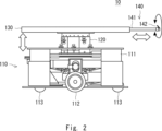
図1は、本実施形態に係る自律移動ロボット10の概略的構成を示す斜視図である。図2は、本実施形態に係る自律移動ロボット10の概略的構成を示す側面図である。図3は、本実施形態に係る自律移動ロボット10の概略的なシステム構成を示すブロック図である。
Hereinafter, an embodiment of the present invention will be described with reference to the drawings.
Fig. 1 is a perspective view showing a schematic configuration of an autonomous
本実施形態に係る自律移動ロボット10は、運搬装置の一例であり、例えば、住宅、施設、倉庫、工場、屋外などの移動環境内を自律的に移動するロボットである。本実施形態に係る自律移動ロボット10は、移動可能な移動部110と、上下方向へ伸縮する伸縮部120と、載置された物体を支持するための載置部130と、アーム140と、アーム駆動機構150と、移動部110、伸縮部120、及びアーム140の制御を含む、自律移動ロボット10の制御を行う制御部100と、無線通信部160とを備えている。
The autonomous
移動部110は、ロボット本体111と、ロボット本体111に回転可能に設けられた左右一対の駆動車輪112及び前後一対の従動車輪113、各駆動車輪112を回転駆動する一対のモータ114と、を有している。各モータ114は減速機などを介して、各駆動車輪112を回転させる。各モータ114は、制御部100からの制御信号に応じて、各駆動車輪112を回転させることで、ロボット本体111の前進移動、後進移動、及び回転を可能にする。これにより、ロボット本体111は、任意の位置に移動することができる。なお、上記移動部110の構成は一例であり、これに限定されない。例えば、移動部110の駆動車輪112及び従動車輪113の数は任意でよく、ロボット本体111を任意の位置に移動させることができれば任意の構成が適用可能である。
The moving
伸縮部120は、上下方向へ伸縮する伸縮機構である。伸縮部120は、テレスコピック型の伸縮機構として構成されていてもよい。伸縮部120の上端部には、載置部130が設けられており、伸縮部120の動作により、載置部130が上昇又は下降する。伸縮部120は、モータなどの駆動装置121を備えており、駆動装置121の駆動により伸縮する。すなわち、駆動装置121の駆動により、載置部130が上昇又は下降する。駆動装置121は、制御部100からの制御信号に応じて駆動する。なお、自律移動ロボット10において、伸縮部120の代わりに、ロボット本体111の上側に設けられた載置部130の高さを制御する公知の任意の機構が用いられてもよい。
The
載置部130は、伸縮部120の上部(先端)に設けられている。載置部130は、モータなどの駆動装置121により昇降し、本実施の形態では、載置部130は、自律移動ロボット10により運搬される物体を載せるために使用される。運搬のため、自律移動ロボット10は、物体を載置部130で支持したまま、物体とともに移動する。これにより、自律移動ロボット10は、物体を運搬する。
The
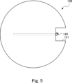
載置部130は、例えば、上面となる板材と下面となる板材とで構成されており、上面と下面との間に、アーム140及びアーム駆動機構150を収める空間を有している。本実施の形態では、この板材の形状、すなわち、載置部130の形状は、例えば平らな円盤状であるが、他の任意の形状であってもよい。なお、より詳細には、本実施の形態では、アーム140の移動の際に、アーム140のラチェット爪142a又はラチェット爪142bが載置部130にぶつからないように、載置部130にはアーム140の動線に沿って切り欠き131が設けられている(図4及び図5参照)。なお、切り欠き131は、少なくとも載置部130の上面に設けられている。
The
載置部130には、載置部130から水平方向に出し入れされるアーム140が設けられている。アーム140は、水平方向に延びる軸部141と、当該軸部141の先端に設けられたラチェット爪142a及び142bとを有する。なお、以下の説明では、ラチェット爪142aとラチェット爪142bについて特に区別することなく言及する場合、ラチェット爪142と称すこととする。また、載置部130には、制御部100からの制御信号に応じて、アーム140の水平方向(すなわち、軸部141に沿った方向、さらに換言するとアーム140の長手方向)の移動及び軸部141の回転を行うアーム駆動機構150が設けられている。アーム駆動機構150は、例えば、モータ及びリニアガイドを含み、アーム140の水平方向の移動及び軸部141の回転を行うが、アーム駆動機構150として、これらの動作を行うための公知の任意の機構が用いられてもよい。
The
このように、アーム140は、水平方向(アーム140の軸部141の方向)に移動可能であるとともに、軸部141の回転に伴いラチェット爪142が回転可能である。すなわち、軸部141を回転軸として、ラチェット爪142が回転可能である。
In this way, the
ここで、アーム140の水平方向の移動について図に示す。図4は、アーム140の先端が載置部130の水平方向の外側に突き出た状態の載置部130の平面図である。また、図5は、アーム140の先端が載置部130側に引き込まれた状態の載置部130の平面図である。なお、載置部130の切り欠き131は、図に示されるように、載置部130の外周端からアーム140の軸に沿って延びた所定の長さの切り欠きである。切り欠き131の終端の位置は、具体的には、例えば、図5に示されるように、アーム140が載置部130側に最も引き込まれた際のアーム140の先端(ラチェット爪142)の位置に相当する位置である。このように、載置部130に切り欠き131があるため、アーム140のラチェット爪142を載置部130の外周の内側まで引き込むことができる。
Here, the horizontal movement of the
なお、本実施形態では、ラチェット爪142が上側を向いた場合、切り欠き131がないとアーム140の動作に支障があるため、切り欠き131が設けられているが、アーム140の動作に支障がない場合には、切り欠き131が設けられていなくてもよい。
In this embodiment, the
アーム140は、ラチェット爪142を備えている。ラチェット爪142は、アーム140(軸部141)の延在方向に沿って設けられている。すなわち、水平面において、ラチェット爪142の爪の先端の向く方向は、アーム140(軸部141)の延在方向である。図6は、アーム140の先端に設けられたラチェット爪142を模式的に示す斜視図である。また、図7は、アーム140の先端に設けられたラチェット爪142を模式的に示す側面図である。図に示すように、本実施の形態では、より詳細には、アーム140は、アーム140(軸部141)の前方に爪の先端143aが向いているラチェット爪142aと、アーム140(軸部141)の後方に爪の先端143bが向いているラチェット爪142bとを備えている。つまり、ラチェット爪142aの爪の先端143aは、アーム140の移動方向前方に向いている。また、ラチェット爪142bの爪の先端143bは、アーム140の移動方向後方に向いている。ラチェット爪142は爪の先端(先端143a及び143b)がアーム140(軸部141)から跳ね上がるように付勢されている。本実施の形態では、一例として、ラチェット爪は、付勢部材144a、144bを用いて、そのように付勢されている。なお、付勢部材144a、144bは、具体的には、例えば、ねじりバネなどのバネである。ラチェット爪142a及びラチェット爪142bは、いずれも、爪の先端がアーム140(軸部141)に近づく方向(図6の矢印で示す方向)に自由に回転可能であるが、当該爪の先端がアーム140(軸部141)から離れる方向には、所定の角度までしか回転できない。具体的には、この所定の角度は、爪と軸部141とのなす角度あり、90度以下の任意の角度である。より詳細には、この所定の角度は、例えば10度以上から90度以下の任意の角度である。ラチェット爪142の爪の先端(先端143a及び143b)は、この所定の角度を維持するよう付勢されている。このようにラチェット爪142は、アーム140(軸部141)に対して垂直な軸を回転軸として付勢の方向とは逆方向には自由に回転可能であるが、付勢の方向には所定の回転角度までしか回転ができないように構成されている。
The
図に示すように、ラチェット爪142aとラチェット爪142bは、アーム140(軸部141)の周方向において互いに離れて設けられている。したがって、アーム140をアーム140の周方向に回転させることにより、ラチェット爪142aとラチェット爪142bのいずれかがアーム140の上方に向くように切り替えることができる。本実施の形態では、より詳細には、ラチェット爪142b(ラチェット爪142a)は、ラチェット爪142a(ラチェット爪142b)に対して垂直に設けられている。すなわち、ラチェット爪142b(ラチェット爪142a)は、周方向において、ラチェット爪142a(ラチェット爪142b)に対して90度離れて設けられている。
As shown in the figure, ratchet
このように、本実施の形態では、アーム140は、爪の向きが逆である2つのラチェット爪142を備えている。このため、第1のラチェット爪を用いて、第1の方向に物体が移動され、第2のラチェット爪を用いて、第2の方向に物体が移動される。このため、後述するように、アーム140を使って、物体を両方向に動かすことができる。
Thus, in this embodiment, the
図3を再び参照して、構成の説明を続ける。
無線通信部160は、必要に応じてサーバ又は他のロボットなどと通信するために、無線通信する回路であり、例えば、無線送受信回路及びアンテナを含む。なお、自律移動ロボット10が他の機器と通信を行わない場合には、無線通信部160が省略されてもよい。
Referring again to FIG. 3, the description of the configuration will continue.
The
制御部100は、自律移動ロボット10を制御する装置であり、プロセッサ101、メモリ102、及びインタフェース103を備える。プロセッサ101、メモリ102、及びインタフェース103は、データバスなどを介して相互に接続されている。
The
インタフェース103は、移動部110、伸縮部120、アーム駆動機構150、無線通信部160などの他の装置と通信するために使用される入出力回路である。
The
メモリ102は、例えば、揮発性メモリ及び不揮発性メモリの組み合わせによって構成される。メモリ102は、プロセッサ101により実行される、1以上の命令を含むソフトウェア(コンピュータプログラム)、及び自律移動ロボット10の各種処理に用いるデータなどを格納するために使用される。
The
プロセッサ101は、メモリ102からソフトウェア(コンピュータプログラム)を読み出して実行することで、制御部100の後述する処理を行う。
The
プロセッサ101は、例えば、マイクロプロセッサ、MPU(Micro Processor Unit)、又はCPU(Central Processing Unit)などであってもよい。プロセッサ101は、複数のプロセッサを含んでもよい。
このように、制御部100は、コンピュータとして機能する装置である。
The
In this manner, the
プログラムは、コンピュータに読み込まれた場合に、実施形態で説明された1又はそれ以上の機能をコンピュータに行わせるための命令群(又はソフトウェアコード)を含む。プログラムは、非一時的なコンピュータ可読媒体又は実体のある記憶媒体に格納されてもよい。限定ではなく例として、コンピュータ可読媒体又は実体のある記憶媒体は、random-access memory(RAM)、read-only memory(ROM)、フラッシュメモリ、solid-state drive(SSD)又はその他のメモリ技術、CD-ROM、digital versatile disc(DVD)、Blu-ray(登録商標)ディスク又はその他の光ディスクストレージ、磁気カセット、磁気テープ、磁気ディスクストレージ又はその他の磁気ストレージデバイスを含む。プログラムは、一時的なコンピュータ可読媒体又は通信媒体上で送信されてもよい。限定ではなく例として、一時的なコンピュータ可読媒体又は通信媒体は、電気的、光学的、音響的、またはその他の形式の伝搬信号を含む。 The program includes instructions (or software code) that, when loaded into a computer, cause the computer to perform one or more functions described in the embodiments. The program may be stored on a non-transitory computer-readable medium or a tangible storage medium. By way of example and not limitation, computer-readable media or tangible storage media include random-access memory (RAM), read-only memory (ROM), flash memory, solid-state drive (SSD) or other memory technology, CD-ROM, digital versatile disc (DVD), Blu-ray (registered trademark) disk or other optical disk storage, magnetic cassette, magnetic tape, magnetic disk storage or other magnetic storage device. The program may be transmitted on a transitory computer-readable medium or communication medium. By way of example and not limitation, transitory computer-readable media or communication media include electrical, optical, acoustic, or other forms of propagated signals.
次に、制御部100の処理について説明する。
制御部100は、自律移動ロボット10の動作を制御する。すなわち、制御部100は、移動部110、伸縮部120、及びアーム140の動作を制御する。制御部100は、移動部110の各モータ114に制御信号を送信することで、各駆動車輪112の回転を制御し、ロボット本体111を任意の位置に移動させることができる。また、制御部100は、伸縮部120の駆動装置121に対して制御信号を送信することで、載置部130の高さを制御することができる。また、制御部100は、アーム駆動機構150に対して制御信号を送信することで、アーム140の水平方向の移動及びラチェット爪142の回転を制御することができる。
このように、制御部100は、ラチェット爪142の水平方向の直線運動を制御する。本実施の形態では、特に、制御部100は、係合部を有する面を備える物体の当該面に沿ってアーム140を移動させる。また、制御部100は、アーム140を当該アーム140の周方向に回転させることで、軸部141を回転軸としたラチェット爪142の回転を制御する。
Next, the processing of the
The
In this manner, the
制御部100は、駆動車輪112に設けられた回転センサにより検出された駆動車輪112の回転情報などに基づいて、フィードバック制御、ロバスト制御等の周知の制御を行うことで、自律移動ロボット10の移動を制御してもよい。また、制御部100は、自律移動ロボット10に設けられたカメラや超音波センサなどの距離センサにより検出された距離情報、移動環境の地図情報などの情報に基づいて、移動部110を制御することで、自律移動ロボット10を自律的に移動させてもよい。
The
ここで、自律移動ロボット10が運搬対象とする物体について具体的に説明する。図8は、ラック80と、ラック80に収納された運搬対象の物体90とを示す模式図である。なお、図8では、ラック80の正面に位置する自律移動ロボット10も図示されている。また、図9は、物体90の正面、底面、及び側面を示す斜視図である。図8に示すように、自律移動ロボット10は、ラック80の物体90を載置部130に移す際、又は、載置部130に置かれた物体90をラック80に移す際、ラック80に近接した位置に移動する。より詳細には、例えば、自律移動ロボット10は、ラック80の正面、かつ、ラック80の対のレール81a、81bの中間地点に移動する。
Here, the object to be transported by the autonomous
ラック80は、物体90の両サイドを支持する対のレール81a、81bを有する。対のレール81a、81bは、同じ高さに平行に設けられている。ラック80に収納された物体90は、物体90の一方のサイドがレール81aにより支持され、他方のサイドがレール81bに支持される。レール81a、81bは、いずれも、ラック80の正面から背面にわたって設けられている。
The
物体90の両サイドには、例えば、図9に示すように、つば91が設けられており、つば91がレール81a、81bに下から支持されることにより、ラック80において物体90が支持される。なお、つば91は、物体90の両サイドに正面から背面にわたって設けられている。図9に示した例では、つば91は、物体90のサイドの上部に設けられているが、例えば下部に設けられてもよく、必ずしも上部でなくてもよい。また、物体90の底面をレール81a、81bが支持する場合には、必ずしもつば91が物体90に設けられていなくてもよい。
For example, as shown in FIG. 9,
このように、ラック80は、物体90の両サイドをレール81a、81bにより下から支持する。そして、物体90は、レール81a、81bに沿って、ラック80内で、前後方向に移動可能である。すなわち、物体90をラック80の背面に向かって押し込むことにより、物体90はラック80に収納される。逆に、物体90をラック80の正面に向かって引き出すことにより、物体90をラック80から取り出すことができる。
In this way, the
図9に示すように、物体90の底面には、アーム140のラチェット爪142を引っ掛けるための係合部92が所定の位置に形成されている。係合部92は、ラチェット爪142の先端が引っ掛かる構造であればよく、具体的には、溝であってもよいし突起であってもよい。また、係合部92として用いられる突起は、物体90の面の強度を上げるために設けられたリブであってもよい。また、図9に示した例では、物体90に設けられている係合部92は一つであるが、所定の方向(つば91の方向、すなわち、ラック80内での物体90の移動方向)に並んだ複数の係合部92が物体90の面に設けられていてもよい。なお、物体90は、例えば、直方体形状の容器(箱)であるが、これに限らず任意の物体でもよい。容器としての物体90の中には、他の任意の物体を収納することができる。
9, an
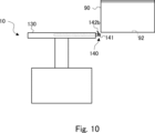
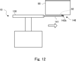
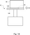
自律移動ロボット10の制御部100は、アーム140を操作することにより、ラック80から載置部130へ物体90を移動させ、又は、載置部130からラック80へ物体90を移動させる。図10から図14は、ラック80に収納された物体90を載置部130に載せる動作を示す模式図である。
The
図10に示すように、まず、制御部100は、アーム140の後方に爪の先端143bが向いているラチェット爪142bが上を向くように、アーム140の軸部141を回転させる。このように、本実施の形態では、アーム140を回転させることで、物体90の移動のために利用するラチェット爪142が切り替えられる。このため、容易に切り換えが行うことができ、利便性が高い。
As shown in FIG. 10, first, the
次に、図11及び図12に示すように、制御部100は、アーム140を載置部130から所定の長さ分だけ送り出す。このとき、図に示されるように、ラチェット爪142bの爪は、物体90の底面により押し下げられるが、付勢部材144bの付勢によって、物体90の底面に接触しながら移動する。制御部100の制御によって、ラチェット爪142bは、物体90の底面の係合部92を超えた位置まで移動する(図12参照)。
Next, as shown in Figures 11 and 12, the
なお、上述した通り、ラチェット爪142aとラチェット爪142bは、周方向において、互いに90度離れて設けられている。このため、ラチェット爪142bが上を向いている間、ラチェット爪142aは、水平方向を向いている。すなわち、ラチェット爪142aは、下を向いていないので、2つのラチェット爪142を含めたアーム140全体の上下方向の幅を抑えることができる。このため、アーム140を狭い隙間に挿入することが容易になる。すなわち、運搬対象の物体90の底面側の狭い空間(例えば、運搬対象の物体90の一段下に収納されている物体90と運搬対象の物体90との狭い隙間)にアーム140を挿入することが容易に実現される。
As described above, ratchet
次に、図13及び図14に示すように、制御部100は、アーム140の先端(ラチェット爪142b)を載置部130に向けて戻す。このとき、係合部92にラチェット爪142bが引っ掛かる(図13参照)。そして、係合部92にラチェット爪142bが引っ掛かると、アーム140の移動にともなって物体90がラック80から引き出され、ラック80から載置部130上へと移動する(図14参照)。このように、本実施の形態では、アーム140を移動させるだけで、ラチェット爪142が物体90の係合部92に係合する。このため、アーム140と物体90とを係合させるための正確な位置合わせの制御を行う必要がなく、容易に物体を移動させることができる。
Next, as shown in FIG. 13 and FIG. 14, the
これに対し、制御部100は、逆の制御を行うことにより、載置部130上の物体90をラック80に収納する。すなわち、制御部100は、載置部130上に載置された物体90の係合部92に引っ掛かったアーム140の先端をラック80に向けて移動することにより、すなわち、係合部92にラチェット爪142aが入った状態でアーム140を載置部130から所定の長さ分だけ送り出すことにより、載置部130上の物体90をラック80に収納することができる。このときも、アーム140を移動させるだけで、ラチェット爪142aが物体90の係合部92に係合する。このため、アーム140と物体90とを係合させるための正確な位置合わせの制御を行う必要がなく、容易に物体を移動させることができる。なお、制御部100は、アーム140の移動に先だって、アーム140の前方に爪の先端143aが向いているラチェット爪142aが上を向くように、アーム140の軸部141を回転させる。
In response to this, the
なお、載置部130とラック80との間で物体を移動する際、載置部130の高さは、物体の移動に適した高さに予め調整されている。すなわち、制御部100は、予め載置部130の高さが所定の高さとなるように制御する。具体的には、制御部100は、載置部130の高さが、ラック80における物体の収納位置の高さに対応する高さとなるよう制御する。つまり、ラック80から載置部130への物体の移動の場合には、制御部100は、載置部130の上面の高さが、ラック80に収納された状態の物体90の底面の高さと対応する高さ(すなわち、同じ高さ)になるように、載置部130の高さを調整する。また、載置部130からラック80への物体90の移動の場合には、制御部100は、載置部130上の物体90のつば91の高さがレール81a、81bの高さとなるように載置部130の高さを調整する。
When an object is moved between the
ところで、上述の通り、物体90の係合部92の数は、複数であってもよい。すなわち、ラック80内での物体90の移動方向に並んだ複数の係合部92が物体90に設けられていてもよい。この場合、制御部100による次のような制御により物体90の移動が実現される。ラック80に収納された物体90を載置部130に移動させる場合、制御部100は、ラチェット爪142bが上を向くようにアーム140を回転させた後、アーム140を載置部130から送り出す制御とアーム140を載置部130に向けて戻す制御とを繰り返せばよい。これにより、複数の係合部92を順番に利用して、少しずつ、物体90がラック80から引き出されることとなる。同様に、載置部130上の物体90をラック80に移動させる場合、制御部100は、ラチェット爪142aが上を向くようにアーム140を回転させた後、アーム140を載置部130に引き込む方向に移動させる制御とアーム140を載置部130から送り出す制御とを繰り返せばよい。これにより、複数の係合部92を順番に利用して、少しずつ、物体90がラック80に押し入れられることとなる。
However, as described above, the number of
図15は、自律移動ロボット10によるラック80から載置部130への物体90の移動動作の流れの一例を示すフローチャートである。なお、自律移動ロボット10は、ラック80の正面の所定位置に予め移動しているものとする。
Figure 15 is a flow chart showing an example of the flow of the movement operation of the autonomous
ステップS100において、制御部100は、ラチェット爪142bが上を向くように、アーム140の軸部141を回転させる。
In step S100, the
次に、ステップS101において、制御部100は、アーム140を送り出す。これにより、ラチェット爪142bは、係合部92を超えた位置、又は、係合部92の位置へと移動する。
Next, in step S101, the
次に、ステップS102において、制御部100は、アーム140(ラチェット爪142b)を戻す。このとき、係合部92にラチェット爪142bが引っ掛かり、アーム140の移動にともなって物体90が載置部130上へと移動する。
Next, in step S102, the
以上の動作により、ラック80から載置部130への物体90の移動が行われる。ただし、上述のように、物体の底面に係合部92が複数設けられている場合には、制御部100は、上述したステップS101からステップS102を繰り返すこととなる。載置部130の上に物体を載せた後、制御部100は、目的地に移動するよう移動部110を制御してもよい。
The above operation moves the
図16は、自律移動ロボット10による載置部130からラック80への物体90の移動動作の流れの一例を示すフローチャートである。なお、自律移動ロボット10は、ラックの正面の所定位置に予め移動しているものとする。
Figure 16 is a flow chart showing an example of the flow of the movement operation of the autonomous
ステップS200において、制御部100は、ラチェット爪142aが上を向くように、アーム140の軸部141を回転させる。
In step S200, the
次に、ステップS201において、制御部100は、アーム140(ラチェット爪142a)を引き込む方向に移動させる。これにより、ラチェット爪142aは、係合部92を超えた位置、又は、係合部92の位置へと移動する。
Next, in step S201, the
次に、ステップS202において、制御部100は、アーム140を送り出す。このとき、係合部92にラチェット爪142aが引っ掛かり、アーム140の移動にともなって物体90がラック80へと移動する。
Next, in step S202, the
次に、ステップS203において、制御部100は、アーム140(ラチェット爪142a)を戻す。このとき、係合部92からラチェット爪142aが外れるため、アーム140だけが戻ることとなる。
Next, in step S203, the
以上の動作により、載置部130からラック80への物体90の移動が行われる。ただし、上述のように、物体の底面に係合部92が複数設けられている場合には、制御部100は、上述したステップS201からステップS202を繰り返すこととなる。
By the above operation, the
以上、実施の形態について説明した。上述したように、本実施の形態にかかる自律移動ロボット10は、ラチェット爪142が設けられたアーム140を備えている。このため、アーム140を移動させるだけで、ラチェット爪142が物体90の係合部92に係合する。したがって、本実施の形態によれば、アーム140と物体90とを係合させるための正確な位置合わせの制御を行う必要がなく、容易に物体を移動させることができる。
The above describes the embodiment. As described above, the autonomous
なお、本発明は上記実施の形態に限られたものではなく、趣旨を逸脱しない範囲で適宜変更することが可能である。例えば、上述した例では、係合部92が物体90の底面に設けられ、制御部100は、物体90の底面に沿ってアーム140を移動させた。しかしながら、係合部92が物体90の他の面(例えば、側面など)に設けられてもよい。この場合、ラチェット爪142を係合部92と係合させるために、制御部100は、係合部92を有する面に沿ってアーム140を移動させればよい。また、上述した例では、アーム140は、2つのラチェット爪142を備え、2方向への物体の移動を可能にしたが、いずれか一方向だけの移動で十分である場合には、アーム140は1つのラチェット爪142を備えればよい。
The present invention is not limited to the above embodiment, and can be modified as appropriate without departing from the spirit of the present invention. For example, in the above example, the engaging
10 自律移動ロボット
80 ラック
90 物体
92 係合部
100 制御部
101 プロセッサ
102 メモリ
103 インタフェース
110 移動部
111 ロボット本体
112 駆動車輪
113 従動車輪
114 モータ
120 伸縮部
121 駆動装置
130 載置部
140 アーム
141 軸部
142 ラチェット爪
150 アーム駆動機構
160 無線通信部
10 Autonomous
Claims (3)
前記アームの動作を制御する制御部と
を有し、
前記アームは、当該アームの前方に爪の先端が向いている第1のラチェット爪と、当該アームの後方に爪の先端が向いている第2のラチェット爪とを備え、
前記第1のラチェット爪と前記第2のラチェット爪は、前記アームの周方向において互いに離れて設けられており、
前記制御部は、前記アームを当該アームの周方向に回転させ、
前記制御部は、係合部を有する面を備える物体の当該面に沿って前記アームを移動させる
運搬装置。 An arm that is movable in a horizontal direction;
A control unit for controlling the operation of the arm,
The arm includes a first ratchet pawl having a tip facing forward of the arm and a second ratchet pawl having a tip facing rearward of the arm,
The first ratchet pawl and the second ratchet pawl are spaced apart from each other in a circumferential direction of the arm,
The control unit rotates the arm in a circumferential direction of the arm,
The control unit moves the arm along a surface of an object having an engagement portion.
請求項1に記載の運搬装置。 2. The transport device of claim 1, wherein the second ratchet pawl is disposed perpendicular to the first ratchet pawl.
請求項1又は2に記載の運搬装置。 The transport device according to claim 1 or 2, wherein the transport device has a mounting portion, the arm is moved in and out horizontally from the mounting portion, and the ratchet pawl engages with the engagement portion provided on a bottom surface of the object.
Priority Applications (3)
| Application Number | Priority Date | Filing Date | Title |
|---|---|---|---|
| JP2022014646A JP7697384B2 (en) | 2022-02-02 | 2022-02-02 | Transport device |
| US18/161,376 US12351442B2 (en) | 2022-02-02 | 2023-01-30 | Conveyance apparatus |
| CN202310125958.2A CN116533205B (en) | 2022-02-02 | 2023-02-01 | Transport device |
Applications Claiming Priority (1)
| Application Number | Priority Date | Filing Date | Title |
|---|---|---|---|
| JP2022014646A JP7697384B2 (en) | 2022-02-02 | 2022-02-02 | Transport device |
Publications (2)
| Publication Number | Publication Date |
|---|---|
| JP2023112751A JP2023112751A (en) | 2023-08-15 |
| JP7697384B2 true JP7697384B2 (en) | 2025-06-24 |
Family
ID=87431517
Family Applications (1)
| Application Number | Title | Priority Date | Filing Date |
|---|---|---|---|
| JP2022014646A Active JP7697384B2 (en) | 2022-02-02 | 2022-02-02 | Transport device |
Country Status (3)
| Country | Link |
|---|---|
| US (1) | US12351442B2 (en) |
| JP (1) | JP7697384B2 (en) |
| CN (1) | CN116533205B (en) |
Families Citing this family (1)
| Publication number | Priority date | Publication date | Assignee | Title |
|---|---|---|---|---|
| WO2026070287A1 (en) * | 2024-09-24 | 2026-04-02 | 京セラドキュメントソリューションズ株式会社 | Unmanned transport vehicle |
Citations (1)
| Publication number | Priority date | Publication date | Assignee | Title |
|---|---|---|---|---|
| JP2015178141A (en) | 2014-03-19 | 2015-10-08 | トヨタ自動車株式会社 | transfer robot and transfer method |
Family Cites Families (14)
| Publication number | Priority date | Publication date | Assignee | Title |
|---|---|---|---|---|
| JPS6313908U (en) | 1986-07-10 | 1988-01-29 | ||
| JPH05286522A (en) * | 1992-04-14 | 1993-11-02 | Matsushita Electric Ind Co Ltd | Part feeding device |
| JP2782304B2 (en) * | 1992-11-11 | 1998-07-30 | 株式会社日立製作所 | Bucket transfer method |
| JPH0769453A (en) | 1993-07-09 | 1995-03-14 | Sankyu Inc | Method of loading or unloading storage freight to or from container and device thereof |
| JP2962153B2 (en) * | 1994-08-08 | 1999-10-12 | 株式会社ダイフク | Transfer equipment |
| JPH1129207A (en) * | 1997-07-11 | 1999-02-02 | Kongo Co Ltd | Load transferring device |
| JP2925520B2 (en) * | 1997-08-12 | 1999-07-28 | 株式会社タイガーマシン製作所 | Dolly storage processing device in multi-stage storage |
| CN101891046B (en) * | 2010-07-22 | 2011-09-07 | 无锡西埃尔斯机械有限公司 | Built-in mobile pallet of container |
| JP5717797B2 (en) * | 2013-06-26 | 2015-05-13 | ファナック株式会社 | Robot hand for conveying article, robot and robot system provided with robot hand, and control method of robot hand |
| CN105775544B (en) * | 2016-05-11 | 2018-05-11 | 深圳普智联科机器人技术有限公司 | Warehousing system and discharging of goods method with easy positioning function |
| CN107458994B (en) * | 2017-09-18 | 2023-05-30 | 广东顺威精密塑料股份有限公司 | A longitudinal double-station semi-automatic stacker |
| CN114873116B (en) * | 2017-11-03 | 2024-09-24 | 拉布拉多系统公司 | Indoor automatic robot system for object picking, placing and transporting |
| US10913641B2 (en) * | 2018-06-08 | 2021-02-09 | Attabotics Inc. | Storage units and robotic storage/retrieval vehicles for a three-dimensional storage system |
| JP7388289B2 (en) * | 2020-05-15 | 2023-11-29 | 株式会社豊田自動織機 | loading equipment |
-
2022
- 2022-02-02 JP JP2022014646A patent/JP7697384B2/en active Active
-
2023
- 2023-01-30 US US18/161,376 patent/US12351442B2/en active Active
- 2023-02-01 CN CN202310125958.2A patent/CN116533205B/en active Active
Patent Citations (1)
| Publication number | Priority date | Publication date | Assignee | Title |
|---|---|---|---|---|
| JP2015178141A (en) | 2014-03-19 | 2015-10-08 | トヨタ自動車株式会社 | transfer robot and transfer method |
Also Published As
| Publication number | Publication date |
|---|---|
| CN116533205A (en) | 2023-08-04 |
| JP2023112751A (en) | 2023-08-15 |
| US12351442B2 (en) | 2025-07-08 |
| CN116533205B (en) | 2026-01-09 |
| US20230242387A1 (en) | 2023-08-03 |
Similar Documents
| Publication | Publication Date | Title |
|---|---|---|
| JP7552414B2 (en) | TRANSPORT SYSTEM AND TRANSPORT METHOD | |
| JP7571597B2 (en) | Conveying System | |
| JP7563212B2 (en) | TRANSPORT SYSTEM AND TRANSPORT METHOD | |
| JP7444014B2 (en) | Transportation system and transportation method | |
| JP7476819B2 (en) | TRANSPORT SYSTEM AND TRANSPORT METHOD | |
| US12129115B2 (en) | Transport system and transport method | |
| JP7697384B2 (en) | Transport device | |
| JP2022124324A (en) | Transport system | |
| US12251819B2 (en) | Transport system with protruding portions | |
| US20220258658A1 (en) | Transport system and transport method | |
| CN114852909A (en) | Conveyance system, control method, and storage medium | |
| CN114104145A (en) | Conveyance system, conveyance method, and program | |
| JP7524882B2 (en) | CONTROL SYSTEM, CONTROL METHOD, AND PROGRAM | |
| JP2024172377A (en) | Transport System | |
| JP7750261B2 (en) | Transport System |
Legal Events
| Date | Code | Title | Description |
|---|---|---|---|
| A621 | Written request for application examination |
Free format text: JAPANESE INTERMEDIATE CODE: A621 Effective date: 20231124 |
|
| A977 | Report on retrieval |
Free format text: JAPANESE INTERMEDIATE CODE: A971007 Effective date: 20240624 |
|
| A131 | Notification of reasons for refusal |
Free format text: JAPANESE INTERMEDIATE CODE: A131 Effective date: 20240625 |
|
| A521 | Request for written amendment filed |
Free format text: JAPANESE INTERMEDIATE CODE: A523 Effective date: 20240821 |
|
| A131 | Notification of reasons for refusal |
Free format text: JAPANESE INTERMEDIATE CODE: A131 Effective date: 20241210 |
|
| A521 | Request for written amendment filed |
Free format text: JAPANESE INTERMEDIATE CODE: A523 Effective date: 20250205 |
|
| TRDD | Decision of grant or rejection written | ||
| A01 | Written decision to grant a patent or to grant a registration (utility model) |
Free format text: JAPANESE INTERMEDIATE CODE: A01 Effective date: 20250513 |
|
| A61 | First payment of annual fees (during grant procedure) |
Free format text: JAPANESE INTERMEDIATE CODE: A61 Effective date: 20250526 |
|
| R150 | Certificate of patent or registration of utility model |
Ref document number: 7697384 Country of ref document: JP Free format text: JAPANESE INTERMEDIATE CODE: R150 |