JP7689435B2 - Work vehicles - Google Patents
Work vehicles Download PDFInfo
- Publication number
- JP7689435B2 JP7689435B2 JP2021056920A JP2021056920A JP7689435B2 JP 7689435 B2 JP7689435 B2 JP 7689435B2 JP 2021056920 A JP2021056920 A JP 2021056920A JP 2021056920 A JP2021056920 A JP 2021056920A JP 7689435 B2 JP7689435 B2 JP 7689435B2
- Authority
- JP
- Japan
- Prior art keywords
- pressure
- accumulator
- time
- pressure oil
- supply circuit
- Prior art date
- Legal status (The legal status is an assumption and is not a legal conclusion. Google has not performed a legal analysis and makes no representation as to the accuracy of the status listed.)
- Active
Links
Images


Landscapes
- Valves And Accessory Devices For Braking Systems (AREA)
- Operation Control Of Excavators (AREA)
- Component Parts Of Construction Machinery (AREA)
Description
本発明は、油圧駆動式の装置に圧油を供給する圧油供給回路上にアキュムレータが設けられた作業車両に関する。 The present invention relates to a work vehicle in which an accumulator is provided on a pressure oil supply circuit that supplies pressure oil to a hydraulically driven device.
作業車両や乗用車といった自動車などの車両用のブレーキ制御システムには、ブレーキ装置に作動液を供給するポンプが故障したり、ポンプを駆動するエンジンやモータが停止したりした場合であってもブレーキ装置が作動できるように、ポンプから吐出された作動液を蓄えておくアキュムレータが備わっている。アキュムレータは、異常が発生して性能が低下すると十分なエネルギーを蓄圧することができなくなってしまう。そのため、アキュムレータの異常を迅速に判定することが求められる。 Brake control systems for vehicles, such as automobiles, including work vehicles and passenger cars, are equipped with accumulators that store hydraulic fluid discharged from the pump so that the brake system can operate even if the pump that supplies hydraulic fluid to the brake system breaks down or the engine or motor that drives the pump stops. If an abnormality occurs in the accumulator and its performance deteriorates, it will no longer be able to store sufficient energy. For this reason, it is necessary to quickly determine whether there is an abnormality in the accumulator.
例えば、特許文献1には、ポンプを駆動するモータと、アキュムレータの作動液圧であるアキュムレータ圧を検出するアキュムレータ圧センサと、検出されたアキュムレータ圧が所定の圧力範囲となるようモータの作動を制御するアキュムレータ圧制御部と、判定の基準となる継続上限時間を設定し、アキュムレータ圧が所定の圧力以下となる状態が設定した継続上限時間以上継続した場合に、アキュムレータ圧が異常であると判定する低圧異常判定部と、を備えたアキュムレータ圧異常判定装置が開示されている。
For example,
ホイールローダなどの作業車両では、1つの油圧ポンプから吐出された圧油を複数の油圧回路に供給することがある。この場合、複数の油圧回路のうち、ブレーキ装置に係る圧油供給回路やステアリング装置に係る圧油供給回路のように作業車両の安全に関わる油圧回路に対しては、優先して圧油を供給する必要がある。そこで、油圧ポンプの吐出側の管路上には優先弁が設けられており、回路圧が予め設定された圧力範囲である場合には、優先すべき圧油供給回路の側に圧油が供給される。 In work vehicles such as wheel loaders, pressure oil discharged from a single hydraulic pump may be supplied to multiple hydraulic circuits. In this case, it is necessary to give priority to supplying pressure oil to hydraulic circuits related to the safety of the work vehicle, such as the pressure oil supply circuit related to the brake device and the pressure oil supply circuit related to the steering device. Therefore, a priority valve is provided in the pipe on the discharge side of the hydraulic pump, and when the circuit pressure is within a preset pressure range, pressure oil is supplied to the pressure oil supply circuit that should be given priority.
したがって、作業車両では、優先すべき圧油供給回路上にアキュムレータが設けられている場合、エンジンが稼働している間は常に、アキュムレータに優先して圧油が供給される。したがって、特許文献1に記載のアキュムレータ圧異常判定装置を作業車両のブレーキシステムに採用した場合、アキュムレータ圧が所定の圧力以下となる状態が設定した継続上限時間以上継続しにくく、アキュムレータの異常を正確に判定することができない。そのため、アキュムレータの蓄圧性能が低下していても、オペレータは、エンジンが稼働している間はアキュムレータの異常に気づくことが難しい。
Therefore, in a work vehicle, if an accumulator is provided on a prioritized pressurized oil supply circuit, pressurized oil is always supplied to the accumulator with priority while the engine is running. Therefore, when the accumulator pressure abnormality determination device described in
アキュムレータの蓄圧性能が低下した状態で作業車両を稼働させ続けると、ブレーキ装置を作動させた際に、アキュムレータに蓄圧されているエネルギーの残量が急激に減ってすぐにゼロに近づいてしまう。そのため、常に油圧ポンプから圧油をアキュムレータに供給する必要があり、油圧ポンプを含む各種機器の作動頻度が増加して負荷が大きくなることから、各種機器が短時間で故障したり、燃費が悪化したりしてしまう。 If a work vehicle continues to operate with the accumulator's pressure storage performance degraded, when the brake device is activated, the remaining amount of energy stored in the accumulator will rapidly decrease and quickly approach zero. This means that it is necessary to constantly supply pressurized oil from the hydraulic pump to the accumulator, which increases the frequency of operation of various equipment, including the hydraulic pump, and places a heavy load on the equipment, causing the equipment to break down in a short period of time and worsening fuel efficiency.
そこで、本発明の目的は、アキュムレータの蓄圧性能の低下を迅速に判定することが可能な作業車両を提供することにある。 The object of the present invention is to provide a work vehicle that can quickly determine a decrease in the pressure storage performance of the accumulator.
上記の目的を達成するために、本発明は、エンジンにより駆動されて圧油を吐出する油圧ポンプと、前記油圧ポンプに対して並列に接続された第1圧油供給回路および第2圧油供給回路と、前記油圧ポンプから吐出された圧油を前記第2圧油供給回路よりも優先して前記第1圧油供給回路に流す優先弁と、前記第1圧油供給回路上に設けられて前記油圧ポンプから吐出された圧油を蓄圧するアキュムレータと、前記アキュムレータの圧力を検出するアキュムレータ圧センサと、前記アキュムレータの蓄圧性能の異常を判定する異常判定装置と、を備えた作業車両において、前記異常判定装置は、前記アキュムレータ圧センサで検出された前記アキュムレータの圧力の変動に基づく特徴パラメータにより、前記アキュムレータの蓄圧性能が正常または異常であるかを判定することを特徴とする。 In order to achieve the above object, the present invention provides a work vehicle including a hydraulic pump driven by an engine to discharge pressurized oil, a first pressure oil supply circuit and a second pressure oil supply circuit connected in parallel to the hydraulic pump, a priority valve that causes the pressure oil discharged from the hydraulic pump to flow to the first pressure oil supply circuit in preference to the second pressure oil supply circuit, an accumulator provided on the first pressure oil supply circuit to accumulate the pressure oil discharged from the hydraulic pump, an accumulator pressure sensor that detects the pressure of the accumulator, and an abnormality determination device that determines an abnormality in the pressure accumulation performance of the accumulator, the abnormality determination device being characterized in that the abnormality determination device determines whether the pressure accumulation performance of the accumulator is normal or abnormal based on a characteristic parameter based on fluctuations in the pressure of the accumulator detected by the accumulator pressure sensor.
本発明によれば、アキュムレータの蓄圧性能の低下を迅速に判定することができる。上記した以外の課題、構成及び効果は、以下の実施形態の説明により明らかにされる。 According to the present invention, it is possible to quickly determine the deterioration of the pressure storage performance of the accumulator. Problems, configurations, and effects other than those described above will become clear from the description of the following embodiment.
以下、本発明の各実施形態に係る作業車両の一態様として、例えば土砂や鉱物といった作業対象物を掘削してダンプトラックなどの積込み先に積み込む荷役作業を行うホイールローダについて説明する。 Below, we will explain a wheel loader, which performs loading and unloading work by digging up work objects such as soil and minerals and loading them onto a loading destination such as a dump truck, as one type of work vehicle according to each embodiment of the present invention.
<ホイールローダ1の構成>
まず、ホイールローダ1の構成について、図1を参照して説明する。
<Configuration of
First, the configuration of a
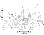
図1は、本発明の各実施形態に係るホイールローダ1の一構成例を示す外観側面図である。
Figure 1 is an external side view showing one configuration example of a
ホイールローダ1は、車体が中心付近で中折れすることにより操舵されるアーティキュレート式の作業車両である。具体的には、車体の前部となる前フレーム1Aと車体の後部となる後フレーム1Bとが、センタジョイント10によって左右方向に回動自在に連結されており、前フレーム1Aが後フレーム1Bに対して左右方向に屈曲する。
The
車体には4つの車輪11が設けられており、2つの車輪11が前輪11Aとして前フレーム1Aの左右両側に、残り2つの車輪11が後輪11Bとして後フレーム1Bの左右両側に、それぞれ設けられている。なお、図1では、4つの車輪11のうち、左側に設けられた前輪11Aおよび後輪11Bのみを示している。また、車体に設けられる複数の車輪11の具体的な数については、特に制限はない。
The vehicle body is provided with four
前フレーム1Aの前部には、荷役作業を行うための油圧駆動式の作業装置2が取り付けられている。作業装置2は、前フレーム1Aに上下方向に回動可能に取り付けられたリフトアーム21と、リフトアーム21を駆動する油圧シリンダとしての2つのリフトアームシリンダ22と、リフトアーム21の先端部に上下方向に回動可能に取り付けられたバケット23と、バケット23を駆動する油圧シリンダとしてのバケットシリンダ24と、リフトアーム21に回動可能に連結されてバケット23とバケットシリンダ24とのリンク機構を構成するベルクランク25と、を有している。なお、2つのリフトアームシリンダ22は車体の左右方向に並んで配置されているが、図1では、左側に配置されたリフトアームシリンダ22のみを破線で示している。
A hydraulically driven
リフトアーム21は、2つのリフトアームシリンダ22のそれぞれのボトム室に圧油が供給されてロッド220が伸びると、前フレーム1Aに対して上方向に回動する。他方、リフトアーム21は、2つのリフトアームシリンダ22のロッド室に圧油が供給されてロッド220が縮むと、前フレーム1Aに対して下方向に回動する。
When pressure oil is supplied to the bottom chambers of the two
バケット23は、バケットシリンダ24のボトム室に圧油が供給されてロッド240が伸びると、リフトアーム21に対して上方向に回動する(チルト動作)。他方、バケット23は、バケットシリンダ24のロッド室に圧油が供給されてロッド240が縮むと、リフトアーム21に対して下方向に回動する(ダンプ動作)。これにより、バケット23は、土砂や鉱物などの作業対象物を掬って排出(放土)することができる。
When pressure oil is supplied to the bottom chamber of the
後フレーム1Bには、オペレータが搭乗する運転室12と、エンジン30(図2参照)などのホイールローダ1の駆動に必要な各機器を内部に収容する機械室13と、車体が傾倒しないように作業装置2とのバランスを保つためのカウンタウェイト14と、が設けられている。後フレーム1Bにおいて、運転室12は前部に、カウンタウェイト14は後部に、機械室13は運転室12とカウンタウェイト14との間に、それぞれ配置されている。
The
次に、ホイールローダ1のブレーキ制御システムについて、実施形態ごとに説明する。
Next, the brake control system for the
<第1実施形態>
本発明の第1実施形態に係るブレーキ制御システム3について、図2~5を参照して説明する。
First Embodiment
A brake control system 3 according to a first embodiment of the present invention will be described with reference to FIGS.
(ブレーキ制御システムの概略構成)
まず、ブレーキ制御システム3の概略構成について、図2および図3を参照して説明する。
(Schematic configuration of brake control system)
First, the schematic configuration of the brake control system 3 will be described with reference to FIGS.
図2は、第1実施形態に係るブレーキ制御システム3の一構成例を示すシステム構成図である。図3は、ブレーキ装置33が作動していない場合におけるアキュムレータ圧Pの時間変化を示すグラフである。
Figure 2 is a system configuration diagram showing an example of the configuration of the brake control system 3 according to the first embodiment. Figure 3 is a graph showing the change in accumulator pressure P over time when the
ホイールローダ1のブレーキ制御システム3は、エンジン30により駆動されて圧油を吐出する油圧ポンプ31と、油圧ポンプ31から吐出された圧油を蓄圧するアキュムレータ32と、油圧ポンプ31あるいはアキュムレータ32から供給された圧油により駆動されて4つの車輪11(図1参照)のそれぞれにブレーキ力(制動力)を付与するブレーキ装置33と、ブレーキ装置33に制御圧力を供給するブレーキ弁34と、アキュムレータ32から油圧ポンプ31側への圧油の逆流を防止する逆止弁35と、を含んで構成される。
The brake control system 3 of the
油圧ポンプ31から吐出された圧油は、第1圧油供給回路としてのブレーキ回路301を介してブレーキ装置33に供給される。すなわち、ブレーキ装置33は、第1圧油供給回路を介して供給された圧油により駆動する油圧駆動装置に相当する。ブレーキ回路301上において、ブレーキ弁34は油圧ポンプ31とブレーキ装置33との間に、アキュムレータ32は油圧ポンプ31とブレーキ弁34との間に、逆止弁35は油圧ポンプ31とアキュムレータ32との間に、それぞれ配置されている。
The pressure oil discharged from the
また、ブレーキ回路301上には、アキュムレータ32の圧力P(以下、単に「アキュムレータ圧P」とする)を検出するアキュムレータ圧センサ32Aと、ブレーキ装置33のブレーキ圧(制動圧)を検出するブレーキ圧センサ33Aと、ブレーキ装置33が作動した際に点灯するブレーキランプのスイッチとしての圧力スイッチ33Bと、が設けられている。
Also provided on the
ブレーキ圧センサ33Aは、所定のブレーキ圧を検出することによってブレーキ装置33の作動を検出することができ、圧力スイッチ33Bは、ブレーキランプを点灯させる側に切り換わることによってブレーキ装置33の作動を検出することができる。したがって、ブレーキ圧センサ33Aおよび圧力スイッチ33Bはいずれも、ブレーキ装置33の作動を検出する作動センサに相当する。なお、作動センサには、ブレーキ弁34に内蔵されたポテンショメータを適用することも可能である。
The
油圧ポンプ31には、ブレーキ回路301の他に、第2圧油供給回路としてのファン回路302が接続されている。すなわち、ブレーキ回路301とファン回路302とは、油圧ポンプ31に対して並列に接続されており、油圧ポンプ31から吐出された圧油は、ブレーキ回路301およびファン回路302の両回路に導かれる。ファン回路302は、機械室13(図1参照)内に設置された冷却ファンを駆動するための回路であり、油圧ポンプ31から吐出された圧油を油圧モータに供給する。ファン回路302の回路圧Ppは、回路圧センサ302Aにより検出される。
In addition to the
ブレーキ回路301は、走行するホイールローダ1の安全に関わる回路であるため、油圧ポンプ31から吐出された圧油をファン回路302よりも優先してブレーキ回路301に流す必要がある。そのため、油圧ポンプ31とブレーキ回路301およびファン回路302との間には優先弁36が設けられている。
Because the
優先弁36は、油圧ポンプ31から吐出された圧油をファン回路302に導く第1弁361と、アキュムレータ圧Pがリリーフ圧以上となった場合に油圧ポンプ31から吐出された圧油をタンク31Bに戻す第2弁362と、を有する。
The
第1弁361には、所定の圧力範囲に設定された付勢力が作用している。アキュムレータ圧Pが所定の圧力以下の場合(アキュムレータ圧Pが所定の圧力範囲を下回る場合)には、第1弁361は、付勢力の作用により閉状態で維持され、油圧ポンプ31から吐出された圧油はブレーキ回路301側に導かれる。一方、アキュムレータ圧Pが所定の圧力よりも大きい場合(アキュムレータ圧Pが所定の圧力範囲を上回る場合)には、第1弁361は、付勢力に抗して開状態に切り換わり、油圧ポンプ31から吐出された圧油はファン回路302側に導かれる。
A biasing force set to a predetermined pressure range acts on the
ここで、「所定の圧力範囲」とは、アキュムレータ32に圧油が蓄圧される場合の圧力範囲であり、図3に示す最低作動圧力P1から最高作動圧力P2へ上昇する圧力範囲(P1→P2)である。アキュムレータ32は、最低作動圧力P1と最高作動圧力P2との間の範囲で作動して、油圧ポンプ31から吐出された圧油の蓄圧とアキュムレータ32に蓄圧された圧油の吐出(消費)とを繰り返す。
The "predetermined pressure range" here refers to the pressure range in which pressure oil is stored in the
具体的には、アキュムレータ32は、アキュムレータ圧Pが最低作動圧力P1以下に下がると(P≦P1)蓄圧を開始し、アキュムレータ圧Pが最高作動圧力P2まで上昇すると(P≧P2)蓄圧を終了する。続いて、圧油で十分に満たされた状態のアキュムレータ32は、続いて、蓄圧された圧油の吐出を開始し、アキュムレータ圧Pが最低作動圧力P1まで低下すると(P≦P1)圧油の吐出を終了する。
Specifically, the
したがって、「最低作動圧力P1」は、アキュムレータ32が作動して蓄圧を開始する最低の圧力として、かつ、アキュムレータ32が圧油の吐出を終了する最低の圧力として設定された圧力である。また、「最高作動圧力P2」は、アキュムレータ32が蓄圧を終了する最高の圧力として、かつ、アキュムレータ32が圧油の吐出を開始する最高の圧力として設定された圧力である。
Therefore, the "minimum operating pressure P1" is the pressure set as the lowest pressure at which the
よって、油圧ポンプ31から吐出された圧油は、アキュムレータ圧Pが最低作動圧力P1に低下した場合に優先弁36によってブレーキ回路301側に導かれ、アキュムレータ圧Pが最高作動圧力P2よりも高くなった場合、すなわちアキュムレータ32に圧油を供給する必要がなくなった場合に優先弁36によってファン回路302側に導かれることになる。
Therefore, the pressurized oil discharged from the
図3において実線で示すように、アキュムレータ32の蓄圧性能が正常である場合には、アキュムレータ32は、時間T1で圧油を蓄圧し、時間T2で圧油を吐出する。換言すれば、アキュムレータ圧Pは、時間T1で最低作動圧力P1から最高作動圧力P2まで上昇し、時間T2で最高作動圧力P2から最低作動圧力P1まで低下する。
As shown by the solid line in Figure 3, when the pressure storage performance of the
なお、以下の説明では、アキュムレータ圧Pが上昇する時間を単に「上昇時間」とし、アキュムレータ圧Pが低下する時間を単に「低下時間」とする場合がある。また、アキュムレータ32の蓄圧性能が正常である場合の上昇時間T1を「第1時間T1」とし、アキュムレータ32の蓄圧性能が正常である場合の低下時間T2を「第2時間T2」とする。
In the following description, the time when the accumulator pressure P rises may be simply referred to as the "rise time", and the time when the accumulator pressure P falls may be simply referred to as the "fall time". In addition, the rise time T1 when the pressure accumulation performance of the
アキュムレータ32の蓄圧性能が低下して異常である場合には、図3において一点鎖線で示すように、アキュムレータ32は、第1時間T1よりも短い時間で最低作動圧力P1から最高作動圧力P2まで上昇し、第2時間T2よりも短い時間で最高作動圧力P2から最低作動圧力P1まで低下する。
When the pressure accumulation performance of the
図3において、一点鎖線で示すグラフの傾きは、実線で示すグラフの傾きよりも急であることが分かる。特に、アキュムレータ32が圧油を吐出する側、すなわち、最高作動圧力P2から最低作動圧力P1まで低下する側における一点鎖線で示すグラフの傾きが、実線で示すグラフの傾きよりも大きい。図3では、正常なアキュムレータ32が、蓄圧を開始してから圧油の吐出を終了する作動サイクル(第1時間T1+第2時間T2)を1サイクル行っている間に、異常なアキュムレータ32は、約2サイクル行うことになる。
In FIG. 3, it can be seen that the slope of the graph indicated by the dashed dotted line is steeper than the slope of the graph indicated by the solid line. In particular, the slope of the graph indicated by the dashed dotted line on the side where the
なお、図3では、ブレーキ装置33が作動していない場合におけるアキュムレータ圧Pの時間変化を示しているが、ブレーキ装置33が作動している場合(図10参照)においても同様に、正常なアキュムレータ32が1サイクル行っている間に、異常なアキュムレータ32は複数サイクル(図10では、約3サイクル)行うことになる。
Note that Figure 3 shows the change in accumulator pressure P over time when the
このように、アキュムレータ32の蓄圧性能が異常である場合、アキュムレータ32の作動回数が正常である場合の作動回数よりも増加し、油圧ポンプ31を含む各種機器の作動頻度が増加して負荷が大きくなる。そこで、ホイールローダ1のブレーキ制御システム3は、図2に示すように、アキュムレータ32の蓄圧性能の異常を判定する異常判定装置5を備えている。
In this way, when the pressure accumulation performance of the
異常判定装置5には、アキュムレータ圧センサ32Aで検出されたアキュムレータ圧Pや回路圧センサ302Aで検出された回路圧Ppに関するデータ、および圧力スイッチ33Bから出力された作動信号などが入力される。また、異常判定装置5には、異常判定装置5における判定結果を報知する報知装置の一態様としてのモニタ4が電気的に接続されている。
The
(異常判定装置5の構成)
次に、異常判定装置5の構成について、図4を参照して説明する。
(Configuration of Abnormality Determination Device 5)
Next, the configuration of the
図4は、異常判定装置5が有する機能を示す機能ブロック図である。
Figure 4 is a functional block diagram showing the functions of the
異常判定装置5は、CPU、RAM、ROM、HDD、入力I/F、および出力I/Fがバスを介して互いに接続されて構成される。そして、圧力スイッチ33Bなどの各種の操作装置やアキュムレータ圧センサ32Aなどの各種のセンサが入力I/Fに接続され、モニタ4などが出力I/Fに接続されている。
The
このようなハードウェア構成において、ROMやHDD若しくは光学ディスク等の記録媒体に格納された制御プログラム(ソフトウェア)をCPUが読み出してRAM上に展開し、展開された制御プログラムを実行することにより、制御プログラムとハードウェアとが協働して、異常判定装置5の機能を実現する。
In such a hardware configuration, the CPU reads out a control program (software) stored in a recording medium such as a ROM, HDD, or optical disk, expands it on the RAM, and executes the expanded control program, whereby the control program and the hardware work together to realize the functions of the
なお、本実施形態では、異常判定装置5をソフトウェアとハードウェアとの組み合わせによって構成されるコンピュータとして説明しているが、これに限らず、例えば他のコンピュータの構成の一例として、ホイールローダ1の側で実行される制御プログラムの機能を実現する集積回路を用いてもよい。
In this embodiment, the
異常判定装置5は、データ取得部51と、時間計測部52と、時間比較部53と、性能判定部54と、記憶部55と、を含む。
The
データ取得部51は、アキュムレータ圧センサ32Aで検出されたアキュムレータ圧Pに関するデータを取得する。
The
時間計測部52は、アキュムレータ圧Pの上昇時間Trを計測する。具体的には、時間計測部52は、データ取得部51で取得されたアキュムレータ圧Pが最低作動圧力P1以下となった場合に(P≦P1)上昇時間Trの計測を開始し、データ取得部51で取得されたアキュムレータ圧Pが最高作動圧力P2以上となった場合に(P≧P2)上昇時間Trの計測を終了する。
The
時間比較部53は、時間計測部52で計測された上昇時間Trと第1時間T1とを比較する。また、本実施形態では、時間比較部53は、時間計測部52で計測された上昇時間Trと第1時間T1よりも長い時間に設定された時間閾値Tth(Tth>T1)とを比較する。第1時間T1および時間閾値Tthはいずれも、メモリとしての記憶部55に記憶されている。
The
性能判定部54は、アキュムレータ圧センサ32Aで検出されたアキュムレータ圧Pの変動に基づく特徴パラメータにより、アキュムレータ32の蓄圧性能が正常または異常であるかを判定する。本実施形態では、「特徴パラメータ」は、アキュムレータ圧Pの上昇時間である。
The
具体的には、性能判定部54は、時間比較部53において上昇時間Trが第1時間T1以上時間閾値Tth未満であると判定された場合には(T1≦Tr<Tth)、アキュムレータ32の蓄圧性能は正常であると判定し、モニタ4に対してアキュムレータ32の正常を示す信号としての正常信号を出力する。
Specifically, when the
一方、性能判定部54は、時間比較部53において上昇時間Trが第1時間T1未満であると判定された場合には(Tr<T1)、アキュムレータ32の蓄圧性能は異常であると判定し、モニタ4に対してアキュムレータ32の異常を示す信号としての異常信号を出力する。
On the other hand, if the
また、本実施形態では、性能判定部54は、時間比較部53において上昇時間Trが時間閾値Tth以上であると判定された場合には(Tr≧Tth)、ブレーキ回路301上におけるアキュムレータ32以外での異常であると判定し、モニタ4に対してアキュムレータ32以外の異常を示す信号としての回路異常信号を出力する。
In addition, in this embodiment, when the
(異常判定装置5内での処理)
次に、異常判定装置5で実行される具体的な処理の流れについて、図5を参照して説明する。
(Processing in the abnormality determination device 5)
Next, a specific flow of processing executed by the
図5は、異常判定装置5で実行される処理の流れを示すフローチャートである。
Figure 5 is a flowchart showing the flow of processing executed by the
異常判定装置5は、まず、データ取得部51が、アキュムレータ圧センサ32Aで検出されるアキュムレータ圧Pを取得する(ステップS501)。次に、ステップS501において取得されたアキュムレータ圧Pが最低作動圧力P1以下である(P≦P1)場合(ステップS502/YES)、時間計測部52は、上昇時間Trの計測を開始する(ステップS503)。なお、ステップS502においてアキュムレータ圧Pが最低作動圧力P1より大きい場合には(ステップS502/NO)、アキュムレータ圧Pが最低作動圧力P1以下になるまでステップS503へ進まない。
In the
続いて、データ取得部51は、アキュムレータ圧センサ32Aで検出されるアキュムレータ圧Pを再取得する(ステップS504)。そして、ステップS504において再取得されたアキュムレータ圧Pが最高作動圧力P2以上である(P≧P2)場合には(ステップS505/YES)、時間計測部52は上昇時間Trの計測を終了する(ステップS506)。
Next, the
他方、ステップS505においてアキュムレータ圧Pが最高作動圧力P2よりも小さい(P<P2)場合には(ステップS505/NO)、アキュムレータ圧Pが最高作動圧力P2以上になるまでステップS506へ進まない。 On the other hand, if the accumulator pressure P is less than the maximum operating pressure P2 (P<P2) in step S505 (step S505/NO), the process does not proceed to step S506 until the accumulator pressure P becomes equal to or greater than the maximum operating pressure P2.
次に、時間比較部53は、時間計測部52で計測された上昇時間Trと記憶部55に記憶されている第1時間T1および時間閾値Tthとを比較し、上昇時間Trが第1時間T1以上であって時間閾値Tth未満であるか否かを判定する(ステップS507)。
Next, the
ステップS507において上昇時間Trが第1時間T1以上であって時間閾値Tth未満である(T1≦Tr<Tth)と判定された場合(ステップS507/YES)、性能判定部54は、アキュムレータ32の蓄圧性能が正常であると判定し、モニタ4に対して正常信号を出力し(ステップS508)、異常判定装置5における処理が終了する。
If it is determined in step S507 that the rise time Tr is equal to or longer than the first time T1 and is less than the time threshold value Tth (T1≦Tr<Tth) (step S507/YES), the
一方、ステップS507において上昇時間Trが第1時間T1以上であって時間閾値Tth未満でないと判定された場合(ステップS507/NO)、時間比較部53は、さらに、上昇時間Trが第1時間T1未満であるか否かを判定する(ステップS509)。
On the other hand, if it is determined in step S507 that the rise time Tr is equal to or greater than the first time T1 and is not less than the time threshold Tth (step S507/NO), the
ステップS509において上昇時間Trが第1時間T1未満である(Tr<T1)と判定された場合(ステップS509/YES)、性能判定部54は、アキュムレータ32の蓄圧性能が異常であると判定し、モニタ4に対して異常信号を出力し(ステップS510)、異常判定装置5における処理が終了する。
If it is determined in step S509 that the rise time Tr is less than the first time T1 (Tr<T1) (step S509/YES), the
ステップS509において上昇時間Trが第1時間T1未満でない、すなわち上昇時間Trが時間閾値Tth以上である(Tr≧Tth)と判定された場合(ステップS509/NO)、性能判定部54は、ブレーキ回路301におけるアキュムレータ32以外の箇所が異常であると判定し、モニタ4に対して回路異常信号を出力し(ステップS511)、異常判定装置5における処理が終了する。
If it is determined in step S509 that the rise time Tr is not less than the first time T1, i.e., that the rise time Tr is equal to or greater than the time threshold value Tth (Tr≧Tth) (step S509/NO), the
このように、異常判定装置5は、アキュムレータ32の蓄圧性能が低下した場合に、その影響を直接的に受けやすいアキュムレータ圧Pの変動を特徴づける上昇時間Trに基づいてアキュムレータ32の蓄圧性能を判定しているため、アキュムレータ32の蓄圧性能の低下を迅速に判定することができる。そして、異常判定装置5がアキュムレータ32の蓄圧性能の低下を素早く判定してモニタ4に異常を表示するため、アキュムレータ32の作動頻度の増加を回避し、ブレーキ回路301上の各機器の劣化や燃費の悪化を抑制することができる。
In this way, the
また、本実施形態では、異常判定装置5は、上昇時間Trが時間閾値Tth以上である(Tr≧Tth)場合には、アキュムレータ32の蓄圧性能の異常と区別してブレーキ回路301におけるアキュムレータ32以外の箇所の異常であると判定しているため、アキュムレータ32の蓄圧性能の異常判定をより精度よく行うことができる。
In addition, in this embodiment, when the rise time Tr is equal to or greater than the time threshold value Tth (Tr≧Tth), the
<第2実施形態>
次に、本発明の第2実施形態に係る異常判定装置5について、図6を参照して説明する。
Second Embodiment
Next, an
図6は、第2実施形態に係る異常判定装置5で実行される処理の流れを示すフローチャートである。なお、本実施形態では、異常判定装置5の機能構成は、第1実施形態に係る異常判定装置5の機能構成と同様であるため、機能ブロック図を省略し、図6に示すフローチャートのみで説明する。図6において、第1実施形態に係る異常判定装置5について説明したものと共通する構成要素については、同一の符号を付してその説明を省略する。
Figure 6 is a flowchart showing the flow of processing executed by the
第1実施形態では、アキュムレータ圧Pの上昇時間Trを特徴パラメータとしていたのに対し、本実施形態では、アキュムレータ圧Pの低下時間Tdを特徴パラメータとする。すなわち、本実施形態に係る異常判定装置5は、アキュムレータ32の圧油の吐出に掛かる時間である低下時間Tdに基づいて、アキュムレータ32の蓄圧性能が正常または異常であるかを判定する。
In the first embodiment, the rise time Tr of the accumulator pressure P is used as the characteristic parameter, whereas in this embodiment, the fall time Td of the accumulator pressure P is used as the characteristic parameter. In other words, the
異常判定装置5は、ステップS501で取得されたアキュムレータ圧Pが最高作動圧力P2以上である(P≧P2)場合に(ステップS521/YES)、時間計測部52は、低下時間Tdの計測を開始する(ステップS522)。ステップS521において、アキュムレータ圧Pが最高作動圧力P2未満である(P<P2)場合には(ステップS521/NO)、アキュムレータ圧Pが最高作動圧力P2以上になるまでステップS522へ進まない。
When the accumulator pressure P acquired in step S501 is equal to or greater than the maximum operating pressure P2 (P≧P2) (step S521/YES), the
次に、ステップS522の後のステップS504において再取得されたアキュムレータ圧Pが最低作動圧力P1以下となった(P≦P1)場合には(ステップS523/YES)、時間計測部52は、低下時間Tdの計測を終了する(ステップS524)。
Next, if the accumulator pressure P reacquired in step S504 after step S522 becomes equal to or lower than the minimum operating pressure P1 (P≦P1) (step S523/YES), the
他方、ステップS523においてアキュムレータ圧Pが最低作動圧力P1よりも大きい(P>P1)場合には(ステップS523/NO)、アキュムレータ圧Pが最低作動圧力P1以下になるまでステップS524へ進まない。 On the other hand, if the accumulator pressure P is greater than the minimum operating pressure P1 (P>P1) in step S523 (step S523/NO), the process does not proceed to step S524 until the accumulator pressure P becomes equal to or lower than the minimum operating pressure P1.
そして、時間比較部53は、時間計測部52で計測された低下時間Tdと記憶部55に記憶されている第2時間T2とを比較し、低下時間Tdが第2時間T2以上であるか否かを判定する(ステップS525)。
Then, the
ステップS525において低下時間Tdが第2時間T2以上である(Td≧T2)と判定された場合(ステップS525/YES)、性能判定部54は、アキュムレータ32の蓄圧性能が正常であると判定し、モニタ4に対して正常信号を出力し(ステップS508)、異常判定装置5における処理が終了する。
If it is determined in step S525 that the drop time Td is equal to or greater than the second time T2 (Td≧T2) (step S525/YES), the
他方、ステップS525において低下時間Tdが第2時間T2未満である(Td<T2)と判定された場合(ステップS525/NO)、性能判定部54は、アキュムレータ32の蓄圧性能が異常であると判定し、モニタ4に対して異常信号を出力し(ステップS510)、異常判定装置5における処理が終了する。
On the other hand, if it is determined in step S525 that the drop time Td is less than the second time T2 (Td<T2) (step S525/NO), the
本実施形態においても、第1実施形態における作用および効果と同様の作用および効果を奏することができる。 This embodiment also provides the same effects and advantages as the first embodiment.
<第3実施形態>
次に、本発明の第3実施形態に係る異常判定装置5について、図7を参照して説明する。
Third Embodiment
Next, an
図7は、第3実施形態に係る異常判定装置5で実行される処理の流れを示すフローチャートである。なお、本実施形態においても、異常判定装置5の機能構成は、第1実施形態に係る異常判定装置5の機能構成と同様であるため、機能ブロック図を省略し、図7に示すフローチャートのみで説明する。図7において、第1および第2実施形態に係る異常判定装置5について説明したものと共通する構成要素については、同一の符号を付してその説明を省略する。
Figure 7 is a flowchart showing the flow of processing executed by the
第1実施形態では、アキュムレータ圧Pの上昇時間Trを特徴パラメータとし、第2実施形態では、アキュムレータ圧Pの低下時間Tdを特徴パラメータとしていたのに対し、本実施形態では、アキュムレータ圧Pの上昇時間Trおよび低下時間Tdの両方を特徴パラメータとする。すなわち、本実施形態に係る異常判定装置5は、アキュムレータ32の蓄圧に掛かる時間である上昇時間Trおよび圧油の吐出に掛かる時間である低下時間Tdに基づいて、アキュムレータ32の蓄圧性能が正常または異常であるかを判定する。
In the first embodiment, the rise time Tr of the accumulator pressure P is the characteristic parameter, and in the second embodiment, the fall time Td of the accumulator pressure P is the characteristic parameter, whereas in this embodiment, both the rise time Tr and fall time Td of the accumulator pressure P are the characteristic parameters. That is, the
異常判定装置5は、まず、第1実施形態におけるステップS501からステップS505までの処理を行う。ステップS505においてアキュムレータ圧Pが最高作動圧力P2以上である(P≧P2)場合には(ステップS505/YES)、時間計測部52は、上昇時間Trの計測を終了すると共に、低下時間Tdの計測を開始する(ステップS526)。
The
次に、データ取得部51は、アキュムレータ圧センサ32Aで検出されるアキュムレータ圧Pを再取得する(ステップS527)。そして、ステップS527において再取得されたアキュムレータ圧Pが最低作動圧力P1以下であった(P≦P1)場合に(ステップS528/YES)、時間計測部52は、低下時間Tdの計測を終了する(ステップS529)。
Next, the
続いて、時間比較部53は、時間計測部52において計測された上昇時間Trが第1時間T1以上であって時間閾値Tth未満であるか否かを判定すると共に、時間計測部52において計測された低下時間Tdが第2時間T2以上であるか否かを判定する(ステップS530)。
Next, the
ステップS530において、上昇時間Trが第1時間T1以上であって時間閾値Tth未満であり(T1≦Tr<Tth)、かつ、低下時間Tdが第2時間T2以上である(Td≧T2)と判定された場合(ステップS530/YES)、性能判定部54は、アキュムレータ32の蓄圧性能が正常であると判定し、モニタ4に対して正常信号を出力し(ステップS508)、異常判定装置5における処理が終了する。
In step S530, if it is determined that the rise time Tr is equal to or greater than the first time T1 and less than the time threshold value Tth (T1≦Tr<Tth) and the fall time Td is equal to or greater than the second time T2 (Td≧T2) (step S530/YES), the
一方、ステップS530において、上昇時間Trが第1時間T1以上であって時間閾値Tth未満であり、かつ、低下時間Tdが第2時間T2以上であると判定されなかった場合(ステップS530/NO)、時間比較部53は、さらに、上昇時間Trが第1時間T1未満であるか否かを判定すると共に、低下時間Tdが第2時間T2未満であるか否かを判定する(ステップS531)。
On the other hand, in step S530, if it is not determined that the rise time Tr is equal to or greater than the first time T1 and less than the time threshold Tth, and the fall time Td is equal to or greater than the second time T2 (step S530/NO), the
ステップS531において、上昇時間Trが第1時間T1未満であり(Tr<T1)、あるいは、低下時間Tdが第2時間T2未満である(Td<T2)と判定された場合(ステップS531/YES)、性能判定部54は、アキュムレータ32の蓄圧性能が異常であると判定し、モニタ4に対して異常信号を出力し(ステップS510)、異常判定装置5における処理が終了する。
In step S531, if it is determined that the rise time Tr is less than the first time T1 (Tr<T1) or the fall time Td is less than the second time T2 (Td<T2) (step S531/YES), the
ステップS531において上昇時間Trが第1時間T1未満でない、または、低下時間Tdが第2時間T2未満でないと判定された場合、すなわち上昇時間Trが時間閾値Tth以上である(Tr≧Tth)と判定された場合(ステップS531/NO)、性能判定部54は、ブレーキ回路301におけるアキュムレータ32以外の箇所が異常であると判定し、モニタ4に対して回路異常信号を出力し(ステップS511)、異常判定装置5における処理が終了する。
If it is determined in step S531 that the rise time Tr is not less than the first time T1 or that the fall time Td is not less than the second time T2, i.e., that the rise time Tr is equal to or greater than the time threshold value Tth (Tr≧Tth) (step S531/NO), the
本実施形態においても、第1実施形態における作用および効果と同様の作用および効果を奏することができる。 This embodiment also provides the same effects and advantages as the first embodiment.
<第4実施形態>
次に、本発明の第4実施形態に係る異常判定装置5Aについて、図8および図9を参照して説明する。
Fourth Embodiment
Next, an
図8は、第4実施形態に係る異常判定装置5Aが有する機能を示す機能ブロック図である。図9は、第4実施形態に係る異常判定装置5Aで実行される処理の流れを示すフローチャートである。図8および図9において、第1~第3実施形態に係る異常判定装置5について説明したものと共通する構成要素については、同一の符号を付してその説明を省略する。
Figure 8 is a functional block diagram showing the functions of the
本実施形態に係る異常判定装置5Aは、図8に示すように、データ取得部51Aと、時間計測部52と、動作状態判定部56と、時間比較部53Aと、性能判定部54と、記憶部55と、を含む。
As shown in FIG. 8, the
データ取得部51Aは、アキュムレータ圧センサ32Aで検出されたアキュムレータ圧Pに加えて、回路圧センサ302Aで検出されたファン回路302の回路圧Ppを取得する。
The
動作状態判定部56は、データ取得部51Aで取得された回路圧Ppが最低作動圧力P1よりも低いか否かを判定する。ここで、動作状態判定部56において回路圧Ppが最低作動圧力P1よりも低い(Pp<P1)と判定される場合とは、優先弁36の第1弁361が開状態に切り替わり、油圧ポンプ31から吐出された圧油がアキュムレータ32へ供給されない状態、換言すれば、油圧ポンプ31から吐出された圧油の全流量が優先弁36によってファン回路302に供給される状態に該当する。したがって、アキュムレータ32は圧油を吐出している状態であるため、異常判定装置5Aは、低下時間Tdに基づいたアキュムレータ32の蓄圧性能の正常または異常判定を精度よく行うことができる。
The operation
図9に示すように、まず、データ取得部51Aは、回路圧センサ302Aで検出された回路圧Ppを取得する(ステップS532)。次に、ステップS532において取得された回路圧Ppが最低作動圧力P1未満である(Pp<P1)場合に(ステップS533/YES)、ステップS501に進み、その後は、第2実施形態に係る異常判定装置5で実行される処理の流れと同様である。
As shown in FIG. 9, first, the
他方、ステップS532において回路圧Ppが最低作動圧力P1以上である(Pp≧P1)と判定された場合には(ステップS533/NO)、回路圧Ppが最低作動圧力P1未満となるまでステップS501へ進まない。 On the other hand, if it is determined in step S532 that the circuit pressure Pp is equal to or greater than the minimum operating pressure P1 (Pp ≥ P1) (step S533/NO), the process does not proceed to step S501 until the circuit pressure Pp becomes less than the minimum operating pressure P1.
本実施形態においても、第1実施形態における作用および効果と同様の作用および効果を奏することができる。 This embodiment also provides the same effects and advantages as the first embodiment.
<第5実施形態>
次に、本発明の第5実施形態に係る異常判定装置5Bについて、図10~12を参照して説明する。
Fifth Embodiment
Next, an
図10は、ブレーキ装置33が作動している場合におけるアキュムレータ圧Pの時間変化を示すグラフである。図11は、第5実施形態に係る異常判定装置5Bが有する機能を示す機能ブロック図である。図12は、第5実施形態に係る異常判定装置5Bで実行される処理の流れを示すフローチャートである。図10~12において、第1~第4実施形態に係る異常判定装置5,5Aについて説明したものと共通する構成要素については、同一の符号を付してその説明を省略する。
Figure 10 is a graph showing the change in accumulator pressure P over time when the
本実施形態に係る異常判定装置5Bは、ブレーキ装置33が作動した場合を考慮して、アキュムレータ32の蓄圧性能が正常または異常であるかを判定する。ブレーキ装置33が作動するとアキュムレータ圧Pは一気に低下するため、図10に示すように、アキュムレータ圧Pの時間変化を示すグラフは、低下側において階段状に下がっていく。
The
アキュムレータ32の蓄圧性能が正常である場合、ブレーキ装置33が1回作動するとアキュムレータ圧Pの低下時間はt1となり、ブレーキ装置33が2回作動するとアキュムレータ圧Pの低下時間はt2となり、ブレーキ装置33が3回作動するとアキュムレータ圧Pの低下時間はt3となる。
If the pressure storage performance of the
これらの低下時間t1,t2,t3は、アキュムレータ32の蓄圧性能が正常であってブレーキ装置33が作動していないときの低下時間である第2時間T2から、ブレーキ装置33を1回作動させたときにアキュムレータ圧Pが低下する時間tdにブレーキ装置33の作動回数Nを乗算したものを減算することにより算出される(t1=T2―td×1,t2=T2―td×2,t3=T2―td×3)。したがって、ブレーキ装置33の作動回数が増えるほど低下時間は短くなる(t1>t2>t3)。すなわち、アキュムレータ32の蓄圧性能が正常であって、ブレーキ装置33が作動している場合におけるアキュムレータ圧Pの低下時間t1,t2,t3は、ブレーキ装置33の作動回数に応じた第2時間T2となる。
These drop times t1, t2, and t3 are calculated by subtracting the time td by which the accumulator pressure P drops when the
また、図10において一点鎖線で示すように、ブレーキ装置33が作動した場合であっても、ブレーキ装置33が作動していない場合と同様に、アキュムレータ32の蓄圧性能が低下している状態では、アキュムレータ32の蓄圧性能が正常である状態(図10において実線で示す)に比べてアキュムレータ圧Pの時間変化が細かくなっており、アキュムレータ32の作動頻度が多くなっている。
In addition, as shown by the dashed line in FIG. 10, even when the
また、アキュムレータ32の蓄圧性能が低下している場合、ブレーキ装置33が作動したときのアキュムレータ圧Pの低下量ΔPが、アキュムレータ32の蓄圧性能が正常な場合における低下量(図10に示すP3からP4を減算した分)より大きくなる。
In addition, when the pressure accumulation performance of the
異常判定装置5Bは、図11に示すように、データ取得部51Bと、時間計測部52と、作動回数カウント部57と、時間比較部53Bと、性能判定部54と、記憶部55Bと、を含む。
As shown in FIG. 11, the
データ取得部51Bは、アキュムレータ圧センサ32Aで検出されたアキュムレータ圧Pに加えて、圧力スイッチ33Bから出力された作動信号を取得する。
The
作動回数カウント部57は、データ取得部51Bにおいて取得された作動信号に基づいてブレーキ装置33の作動回数をカウントする。なお、本実施形態では、作動回数カウント部57は、圧力スイッチ33Bから出力される作動信号(ブレーキランプの点灯信号)に基づいてブレーキ装置33の作動回数をカウントしているが、これに限らず、ブレーキ圧センサ33Aやブレーキ弁34に内蔵されたポテンショメータからのデータ信号に基づいてブレーキ装置33の作動回数をカウントしてもよい。
The
記憶部55Bには、ブレーキ装置33の作動回数N1,N2,N3・・・に応じた第2時間t1,t2,t3・・・がそれぞれ記憶されている。時間比較部53Bは、時間計測部52において計測された低下時間Tdとブレーキ装置33の作動回数N1,N2,N3・・・に応じた第2時間t1,t2,t3・・・とを比較する。
The
図12に示すように、異常判定装置5Bは、ステップS502においてアキュムレータ圧Pが最高作動圧力P2以上となった(P≧P2)場合に(ステップS502/YES)、時間計測部52が低下時間Tdの計測を開始すると共に、作動回数カウント部57がブレーキ装置33の作動回数Nのカウントを開始する(ステップS534)。
As shown in FIG. 12, when the accumulator pressure P becomes equal to or greater than the maximum operating pressure P2 (P≧P2) in step S502 (step S502/YES), the
続いて、ステップS504で再取得されたアキュムレータ圧Pが最低作動圧力P1以下となった(P≦P1)場合に(ステップS505/YES)、時間計測部52が低下時間Tdの計測を終了すると共に、作動回数カウント部57がブレーキ装置33の作動回数Nのカウントを終了する(ステップS535)。
Next, when the accumulator pressure P reacquired in step S504 becomes equal to or lower than the minimum operating pressure P1 (P≦P1) (step S505/YES), the
そして、時間比較部53Bは、作動回数カウント部57でカウントされた作動回数NがN1(=1回)以下であって、かつ、時間計測部52で計測された低下時間Tdが作動回数N1に応じた第2時間t1以上であるか否かを判定する(ステップS536)。
Then, the
ステップS536において、作動回数NがN1以下であって(N≦N1)、かつ、低下時間Tdが作動回数N1に応じた第2時間t1以上である(Td≧t1)と判定された場合(ステップS536/YES)、性能判定部54は、アキュムレータ32の蓄圧性能が正常であると判定してモニタ4に対して正常信号を出力し(ステップS508)、異常判定装置5Bにおける処理が終了する。
In step S536, if it is determined that the number of activations N is equal to or less than N1 (N≦N1) and the drop time Td is equal to or greater than the second time t1 corresponding to the number of activations N1 (Td≧t1) (step S536/YES), the
一方、ステップS536において、作動回数NがN1以下でない(N>N1)、あるいは、低下時間Tdが作動回数N1に応じた第2時間t1未満である(Td<t1)と判定された場合(ステップS536/NO)、時間比較部53Bは、さらに、作動回数NがN2(=2回)以下であって、かつ、低下時間Tdが作動回数N2に応じた第2時間t2以上であるか否かを判定する(ステップS537)。
On the other hand, if it is determined in step S536 that the number of activations N is not equal to or less than N1 (N>N1) or that the drop time Td is less than the second time t1 corresponding to the number of activations N1 (Td<t1) (step S536/NO), the
ステップS537において、作動回数NがN2以下であって(N≦N2)、かつ、低下時間Tdが作動回数N2に応じた第2時間t2以上である(Td≧t2)と判定された場合(ステップS537/YES)、ステップS508に進み、性能判定部54は、アキュムレータ32の蓄圧性能が正常であると判定してモニタ4に対して正常信号を出力する。
In step S537, if it is determined that the number of activations N is equal to or less than N2 (N≦N2) and the drop time Td is equal to or greater than the second time t2 corresponding to the number of activations N2 (Td≧t2) (step S537/YES), the process proceeds to step S508, where the
ステップS537において、作動回数NがN2以下でない(N>N2)、かつ、低下時間Tdが作動回数N2に応じた第2時間t2未満である(Td<t2)と判定された場合(ステップS537/NO)、性能判定部54は、アキュムレータ32の蓄圧性能が異常であると判定してモニタ4に対して異常信号を出力し(ステップS510)、異常判定装置5Bにおける処理が終了する。
In step S537, if it is determined that the number of activations N is not equal to or less than N2 (N>N2) and the drop time Td is less than the second time t2 corresponding to the number of activations N2 (Td<t2) (step S537/NO), the
本実施形態においても、第1実施形態における作用および効果と同様の作用および効果を奏することができる。 This embodiment also provides the same effects and advantages as the first embodiment.
<第6実施形態>
次に、本発明の第6実施形態に係る異常判定装置5Cについて、図13および図14を参照して説明する。
Sixth Embodiment
Next, an
図13は、第6実施形態に係る異常判定装置5Cが有する機能を示す機能ブロック図である。図14は、第6実施形態に係る異常判定装置5Cで実行される処理の流れを示すフローチャートである。図13および図14において、第1~第5実施形態に係る異常判定装置5,5A,5Bについて説明したものと共通する構成要素については、同一の符号を付してその説明を省略する。
Figure 13 is a functional block diagram showing the functions of the
本実施形態に係る異常判定装置5Cは、第5実施形態に係る異常判定装置5Bと同様に、ブレーキ装置33が作動した場合を考慮して、アキュムレータ32の蓄圧性能が正常または異常であるかを判定する。
The
前述したように、アキュムレータ32の蓄圧性能が低下している場合、ブレーキ装置33が作動したときのアキュムレータ圧Pの低下量ΔPが、アキュムレータ32の蓄圧性能が正常な場合における低下量(図10に示すP3からP4を減算した分)より大きくなる。そこで、本実施形態に係る異常判定装置5Cでは、特徴パラメータをブレーキ装置33が作動した際のアキュムレータ圧Pの低下量ΔPとする。
As described above, when the pressure accumulation performance of the
図13に示すように、異常判定装置5Cは、データ取得部51Cと、低下量算出部58と、低下量比較部59と、性能判定部54Cと、記憶部55Cと、を含む。
As shown in FIG. 13, the
データ取得部51Cは、アキュムレータ圧センサ32Aで検出されたアキュムレータ圧Pに加えて、圧力スイッチ33Bから出力された作動信号(ブレーキ作動信号)を取得する。
The
低下量算出部58は、データ取得部51Cで取得されたアキュムレータ圧Pおよびブレーキ作動信号に基づいて、アキュムレータ圧Pの低下量ΔPを算出する。
The reduction
低下量比較部59は、低下量算出部58において算出された低下量ΔPとアキュムレータ32の蓄圧性能が正常である場合の低下量ΔP1(=P3―P4)とを比較する。なお、低下量ΔP1は、記憶部55Cに予め記憶されている。
The decrease
性能判定部54Cは、低下量比較部59において低下量ΔPがΔP1以下である(ΔP≦ΔP1)と判定された場合、アキュムレータ32の蓄圧性能が正常であると判定し、モニタ4に対して正常信号を出力する。一方、性能判定部54Cは、低下量比較部59において低下量ΔPがΔP1よりも大きい(ΔP>ΔP1)と判定された場合、アキュムレータ32の蓄圧性能が異常であると判定し、モニタ4に対して異常信号を出力する。
When the decrease
図14に示すように、異常判定装置5Cは、まず、データ取得部51Cがアキュムレータ圧センサ32Aで検出されるアキュムレータ圧Pを取得する(ステップS501)。次に、データ取得部51Cが圧力スイッチ33Bからのブレーキ作動信号を取得すると(ステップS538/YES)、その直前(データ取得部51Cがブレーキ作動信号を取得する直前)のアキュムレータ圧Pを記録する(ステップS539)。なお、ステップS538において圧力スイッチ33Bからブレーキ作動信号が出力されなかった場合には(ステップS538/NO)、ステップS501に戻って処理を繰り返す。
As shown in FIG. 14, in the
続いて、圧力スイッチ33Bからブレーキ作動信号が出力されなくなると(ステップS538A/YES)、データ取得部51Cは、引き続きアキュムレータ圧Pを再取得する(ステップS540)。一方、ステップS538Aにおいて圧力スイッチ33Bからブレーキ作動信号が出力されている場合には(ステップS538A/NO)、ブレーキ作動信号が出力されなくなるまでステップS540に進まない。
Next, when the brake activation signal is no longer output from the
そして、低下量算出部58は、ステップS539において記録されたアキュムレータ圧PとステップS540で取得されたアキュムレータ圧Pとから、アキュムレータ圧Pの低下量ΔPを算出する(ステップS541)。
Then, the reduction
続いて、低下量比較部59は、ステップS541において算出された低下量ΔPがアキュムレータ32の蓄圧性能が正常である場合における低下量ΔP1以下であるか否かを判定する(ステップS542)。
Next, the decrease
ステップS542において低下量ΔPが低下量ΔP1以下である(ΔP≦ΔP1)と判定された場合(ステップS542/YES)、性能判定部54Cは、アキュムレータ32の蓄圧性能が正常であると判定してモニタ4に対して正常信号を出力し(ステップS508)、異常判定装置5Cにおける処理が終了する。
If it is determined in step S542 that the decrease amount ΔP is equal to or less than the decrease amount ΔP1 (ΔP≦ΔP1) (step S542/YES), the
一方、ステップS542において低下量ΔPが低下量ΔP1より大きい(ΔP>ΔP1)と判定された場合(ステップS542/NO)、性能判定部54Cは、アキュムレータ32の蓄圧性能が異常であると判定してモニタ4に対して異常信号を出力し(ステップS510)、異常判定装置5Cにおける処理が終了する。
On the other hand, if it is determined in step S542 that the decrease amount ΔP is greater than the decrease amount ΔP1 (ΔP>ΔP1) (step S542/NO), the
本実施形態においても、第1実施形態における作用および効果と同様の作用および効果を奏することができる。 This embodiment also provides the same effects and advantages as the first embodiment.
以上、本発明の実施形態について説明した。なお、本発明は上記した実施形態に限定されるものではなく、様々な変形例が含まれる。例えば、上記した実施形態は本発明を分かりやすく説明するために詳細に説明したものであり、必ずしも説明した全ての構成を備えるものに限定されるものではない。また、本実施形態の構成の一部を他の実施形態の構成に置き換えることが可能であり、また、本実施形態の構成に他の実施形態の構成を加えることも可能である。またさらに、本実施形態の構成の一部について、他の構成の追加・削除・置換をすることが可能である。 The above describes an embodiment of the present invention. Note that the present invention is not limited to the above embodiment, and various modified examples are included. For example, the above embodiment has been described in detail to clearly explain the present invention, and is not necessarily limited to having all of the configurations described. It is also possible to replace part of the configuration of this embodiment with the configuration of another embodiment, and it is also possible to add the configuration of another embodiment to the configuration of this embodiment. Furthermore, it is also possible to add, delete, or replace part of the configuration of this embodiment with other configurations.
例えば、上記実施形態では、作業車両の一態様としてホイールローダ1を例に挙げて説明したが、これに限らず、優先弁36を備えた作業車両であれば本発明を適用することが可能である。
For example, in the above embodiment, a
また、上記実施形態では、第1油圧供給回路を介して供給された圧油により駆動される油圧駆動装置としてブレーキ装置33を例に挙げて説明したが、これに限らず、例えばステアリング装置などであってもよい。
In the above embodiment, the
1:ホイールローダ(作業車両)
5,5A,5B,5C:異常判定装置
30:エンジン
31:油圧ポンプ
32:アキュムレータ
32A:アキュムレータ圧センサ
36:優先弁
301:ブレーキ回路(第1圧油供給回路)
302:ファン回路(第2圧油供給回路)
P:アキュムレータ圧
P1:最低作動圧力
P2:最高作動圧力
Tr:上昇時間(特徴パラメータ)
Td:低下時間(特徴パラメータ)
T1:第1時間
T2,t1,t2,t3:第2時間
ΔP:低下量(特徴パラメータ)
1: Wheel loader (work vehicle)
5, 5A, 5B, 5C: Abnormality determination device 30: Engine 31: Hydraulic pump 32:
302: Fan circuit (second pressure oil supply circuit)
P: accumulator pressure P1: minimum operating pressure P2: maximum operating pressure Tr: rise time (characteristic parameter)
Td: Decay time (characteristic parameter)
T1: first time T2, t1, t2, t3: second time ΔP: decrease amount (characteristic parameter)
Claims (4)
前記油圧ポンプに対して並列に接続された第1圧油供給回路および第2圧油供給回路と、
前記油圧ポンプから吐出された圧油を前記第2圧油供給回路よりも優先して前記第1圧油供給回路に流す優先弁と、
前記第1圧油供給回路上に設けられて前記油圧ポンプから吐出された圧油を蓄圧するアキュムレータと、
前記アキュムレータの圧力を検出するアキュムレータ圧センサと、
前記アキュムレータの蓄圧性能の異常を判定する異常判定装置と、
を備えた作業車両において、
前記異常判定装置は、
前記アキュムレータ圧センサで検出された前記アキュムレータの圧力の変動に基づく特徴パラメータにより、前記アキュムレータの蓄圧性能が正常または異常であるかを判定し、
前記アキュムレータの圧力が、前記アキュムレータが作動して蓄圧を開始する最低の圧力として設定された最低作動圧力から前記アキュムレータが蓄圧を終了する最高の圧力として設定された最高作動圧力に上昇するまでの上昇時間を前記特徴パラメータとし、
前記アキュムレータ圧センサで検出された前記アキュムレータの圧力に基づいて前記上昇時間を計測し、
計測された前記上昇時間が前記アキュムレータの蓄圧性能が正常である場合の前記上昇時間である第1時間よりも短い場合に、前記アキュムレータの蓄圧性能が異常であると判定し、
計測された前記上昇時間が前記第1時間よりも長い時間に設定された時間閾値以上である場合には、前記第1圧油供給回路上における前記アキュムレータ以外の異常であると判定する
ことを特徴とする作業車両。 A hydraulic pump driven by the engine to discharge pressure oil;
a first pressure oil supply circuit and a second pressure oil supply circuit connected in parallel to the hydraulic pump;
a priority valve that causes the pressure oil discharged from the hydraulic pump to flow to the first pressure oil supply circuit in preference to the second pressure oil supply circuit;
an accumulator provided on the first pressure oil supply circuit and configured to accumulate pressure oil discharged from the hydraulic pump;
an accumulator pressure sensor that detects the pressure of the accumulator;
an abnormality determination device that determines an abnormality in the pressure accumulation performance of the accumulator;
In a work vehicle equipped with
The abnormality determination device includes:
determining whether a pressure accumulation performance of the accumulator is normal or abnormal based on a characteristic parameter based on a fluctuation in the pressure of the accumulator detected by the accumulator pressure sensor;
the characteristic parameter is a rise time of the pressure of the accumulator from a minimum operating pressure set as a minimum pressure at which the accumulator operates and starts accumulating pressure to a maximum operating pressure set as a maximum pressure at which the accumulator ends accumulating pressure;
measuring the rise time based on the pressure of the accumulator detected by the accumulator pressure sensor;
When the measured rise time is shorter than a first time, which is the rise time when the pressure accumulation performance of the accumulator is normal, it is determined that the pressure accumulation performance of the accumulator is abnormal;
a work vehicle comprising: a pressure sensor configured to detect an abnormality in a pressure range of the first pressure oil supply circuit and an accumulator configured to detect an abnormality in the pressure range of the first pressure oil supply circuit;
前記油圧ポンプに対して並列に接続された第1圧油供給回路および第2圧油供給回路と、
前記油圧ポンプから吐出された圧油を前記第2圧油供給回路よりも優先して前記第1圧油供給回路に流す優先弁と、
前記第1圧油供給回路上に設けられて前記油圧ポンプから吐出された圧油を蓄圧するアキュムレータと、
前記アキュムレータの圧力を検出するアキュムレータ圧センサと、
前記アキュムレータの蓄圧性能の異常を判定する異常判定装置と、
を備えた作業車両において、
前記第2圧油供給回路の圧力を検出する回路圧センサを有し、
前記異常判定装置は、
前記アキュムレータ圧センサで検出された前記アキュムレータの圧力の変動に基づく特徴パラメータにより、前記アキュムレータの蓄圧性能が正常または異常であるかを判定し、
前記アキュムレータの圧力が、前記アキュムレータが作動して圧油の吐出を開始する最高の圧力として設定された最高作動圧力から前記アキュムレータが圧油の吐出を終了する最低の圧力として設定された最低作動圧力に低下するまでの低下時間を前記特徴パラメータとし、
前記アキュムレータ圧センサで検出された前記アキュムレータの圧力に基づいて前記低下時間を計測し、
計測された前記低下時間が前記アキュムレータの蓄圧性能が正常である場合の前記低下時間である第2時間よりも短い場合に、前記アキュムレータの蓄圧性能が異常であると判定し、
前記回路圧センサで検出された前記第2圧油供給回路の圧力が前記最低作動圧力よりも低い場合に、前記低下時間に基づいて前記アキュムレータの蓄圧性能が正常または異常であるかを判定する
ことを特徴とする作業車両。 A hydraulic pump driven by the engine to discharge pressure oil;
a first pressure oil supply circuit and a second pressure oil supply circuit connected in parallel to the hydraulic pump;
a priority valve that causes the pressure oil discharged from the hydraulic pump to flow to the first pressure oil supply circuit in preference to the second pressure oil supply circuit;
an accumulator provided on the first pressure oil supply circuit and configured to accumulate pressure oil discharged from the hydraulic pump;
an accumulator pressure sensor that detects the pressure of the accumulator;
an abnormality determination device that determines an abnormality in the pressure accumulation performance of the accumulator;
In a work vehicle equipped with
a circuit pressure sensor for detecting a pressure in the second pressure oil supply circuit,
The abnormality determination device includes:
determining whether a pressure accumulation performance of the accumulator is normal or abnormal based on a characteristic parameter based on a fluctuation in the pressure of the accumulator detected by the accumulator pressure sensor;
the characteristic parameter is a time period during which the pressure of the accumulator decreases from a maximum operating pressure set as the maximum pressure at which the accumulator operates and starts discharging pressure oil to a minimum operating pressure set as the minimum pressure at which the accumulator stops discharging pressure oil,
measuring the decrease time based on the pressure of the accumulator detected by the accumulator pressure sensor;
When the measured decrease time is shorter than a second time, which is the decrease time when the pressure accumulation performance of the accumulator is normal, it is determined that the pressure accumulation performance of the accumulator is abnormal;
a pressure drop time period during which the pressure in the accumulator is normal or abnormal is determined based on the decrease time period when the pressure in the second pressure oil supply circuit detected by the circuit pressure sensor is lower than the minimum operating pressure .
前記第1圧油供給回路を介して供給された圧油により駆動する油圧駆動装置と、
前記油圧駆動装置の作動を検出し、前記油圧駆動装置が作動されたことを示す作動信号を前記異常判定装置に対して出力する作動センサと、を有し、
前記異常判定装置は、
前記作動センサから出力された前記作動信号に基づいて前記油圧駆動装置の作動回数をカウントし、
計測された前記低下時間が、カウントされた前記油圧駆動装置の前記作動回数に応じた前記第2時間よりも短い場合に、前記アキュムレータの蓄圧性能が異常であると判定する
ことを特徴とする作業車両。 The work vehicle according to claim 2,
a hydraulic drive device that is driven by pressure oil supplied via the first pressure oil supply circuit;
an operation sensor that detects operation of the hydraulic drive system and outputs an operation signal indicating that the hydraulic drive system has been operated to the abnormality determination device;
The abnormality determination device includes:
Counting the number of operations of the hydraulic drive device based on the operation signal output from the operation sensor;
a pressure storage performance of the accumulator being determined to be abnormal if the measured decrease time is shorter than a second time corresponding to the counted number of operations of the hydraulic drive device .
前記油圧ポンプに対して並列に接続された第1圧油供給回路および第2圧油供給回路と、
前記油圧ポンプから吐出された圧油を前記第2圧油供給回路よりも優先して前記第1圧油供給回路に流す優先弁と、
前記第1圧油供給回路上に設けられて前記油圧ポンプから吐出された圧油を蓄圧するアキュムレータと、
前記アキュムレータの圧力を検出するアキュムレータ圧センサと、
前記アキュムレータの蓄圧性能の異常を判定する異常判定装置と、
を備えた作業車両において、
前記第1圧油供給回路を介して供給された圧油により駆動する油圧駆動装置と、
前記油圧駆動装置の作動を検出し、前記油圧駆動装置が作動されたことを示す作動信号を前記異常判定装置に対して出力する作動センサと、を有し、
前記異常判定装置は、
前記アキュムレータ圧センサで検出された前記アキュムレータの圧力の変動に基づく特徴パラメータにより、前記アキュムレータの蓄圧性能が正常または異常であるかを判定し、
前記油圧駆動装置が作動した際の前記アキュムレータの圧力の低下量を前記特徴パラメータとし、
前記作動センサから出力された前記作動信号および前記アキュムレータ圧センサで検出された前記アキュムレータの圧力に基づいて前記低下量を算出し、
算出された前記低下量が、前記アキュムレータの蓄圧性能が正常である場合の前記低下量よりも多い場合に、前記アキュムレータの蓄圧性能が異常であると判定する
ことを特徴とする作業車両。 A hydraulic pump driven by the engine to discharge pressure oil;
a first pressure oil supply circuit and a second pressure oil supply circuit connected in parallel to the hydraulic pump;
a priority valve that causes the pressure oil discharged from the hydraulic pump to flow to the first pressure oil supply circuit in preference to the second pressure oil supply circuit;
an accumulator provided on the first pressure oil supply circuit and configured to accumulate pressure oil discharged from the hydraulic pump;
an accumulator pressure sensor that detects the pressure of the accumulator;
an abnormality determination device that determines an abnormality in the pressure accumulation performance of the accumulator;
In a work vehicle equipped with
a hydraulic drive device that is driven by pressure oil supplied via the first pressure oil supply circuit;
an operation sensor that detects operation of the hydraulic drive system and outputs an operation signal indicating that the hydraulic drive system has been operated to the abnormality determination device;
The abnormality determination device includes:
determining whether a pressure accumulation performance of the accumulator is normal or abnormal based on a characteristic parameter based on a fluctuation in the pressure of the accumulator detected by the accumulator pressure sensor;
The characteristic parameter is a pressure drop amount of the accumulator when the hydraulic drive device is operated,
calculating the amount of decrease based on the actuation signal output from the actuation sensor and the pressure of the accumulator detected by the accumulator pressure sensor;
A work vehicle comprising: a pressure storage performance control unit that determines that the pressure storage performance of the accumulator is abnormal when the calculated amount of decrease is greater than the amount of decrease when the pressure storage performance of the accumulator is normal .
Priority Applications (1)
| Application Number | Priority Date | Filing Date | Title |
|---|---|---|---|
| JP2021056920A JP7689435B2 (en) | 2021-03-30 | 2021-03-30 | Work vehicles |
Applications Claiming Priority (1)
| Application Number | Priority Date | Filing Date | Title |
|---|---|---|---|
| JP2021056920A JP7689435B2 (en) | 2021-03-30 | 2021-03-30 | Work vehicles |
Publications (3)
| Publication Number | Publication Date |
|---|---|
| JP2022154063A JP2022154063A (en) | 2022-10-13 |
| JP2022154063A5 JP2022154063A5 (en) | 2024-03-25 |
| JP7689435B2 true JP7689435B2 (en) | 2025-06-06 |
Family
ID=83557225
Family Applications (1)
| Application Number | Title | Priority Date | Filing Date |
|---|---|---|---|
| JP2021056920A Active JP7689435B2 (en) | 2021-03-30 | 2021-03-30 | Work vehicles |
Country Status (1)
| Country | Link |
|---|---|
| JP (1) | JP7689435B2 (en) |
Families Citing this family (1)
| Publication number | Priority date | Publication date | Assignee | Title |
|---|---|---|---|---|
| JP2024111514A (en) * | 2023-02-06 | 2024-08-19 | 株式会社小松製作所 | Working machine, working machine system, and working machine control method |
Citations (1)
| Publication number | Priority date | Publication date | Assignee | Title |
|---|---|---|---|---|
| JP2002114497A (en) | 2000-10-04 | 2002-04-16 | Toyota Industries Corp | Replenishment abnormality diagnostic device, accumulation abnormality diagnostic device, fluid type operation controller, hydraulic operation controller and brake device, for industrial vehicle |
Family Cites Families (2)
| Publication number | Priority date | Publication date | Assignee | Title |
|---|---|---|---|---|
| JP6842393B2 (en) * | 2017-09-11 | 2021-03-17 | 日立建機株式会社 | Pressure oil energy recovery device for work machines |
| JP6982561B2 (en) * | 2018-11-29 | 2021-12-17 | 日立建機株式会社 | Construction machinery |
-
2021
- 2021-03-30 JP JP2021056920A patent/JP7689435B2/en active Active
Patent Citations (1)
| Publication number | Priority date | Publication date | Assignee | Title |
|---|---|---|---|---|
| JP2002114497A (en) | 2000-10-04 | 2002-04-16 | Toyota Industries Corp | Replenishment abnormality diagnostic device, accumulation abnormality diagnostic device, fluid type operation controller, hydraulic operation controller and brake device, for industrial vehicle |
Also Published As
| Publication number | Publication date |
|---|---|
| JP2022154063A (en) | 2022-10-13 |
Similar Documents
| Publication | Publication Date | Title |
|---|---|---|
| EP3290265B1 (en) | Method and system for operating a tipper | |
| CN101932463B (en) | Suspension system | |
| US8428823B2 (en) | Steering control device and steering control method for working vehicle | |
| JP7076396B2 (en) | Work machine | |
| CN103946505B (en) | Cooling fan controller | |
| EP2886724A2 (en) | System and method for controlling a work vehicle based on a monitored tip condition of the vehicle | |
| WO1997037117A1 (en) | Vehicle running control device | |
| JP5565273B2 (en) | Industrial vehicle | |
| EP3064398B1 (en) | Method and system for operating a tipper | |
| CN110337545B (en) | Hydraulic oil energy recovery device for work machinery | |
| JP7689435B2 (en) | Work vehicles | |
| EP3967880B1 (en) | Hydraulic actuator control device for dump truck | |
| US8548692B2 (en) | Travel vibration suppressing device of work vehicle | |
| EP3064783A1 (en) | Method and system for generating an alert relating to a hydraulic actuation system | |
| US20210123216A1 (en) | Loading vehicle | |
| JP2009264455A (en) | Accumulator gas pressure drop detecting method and device | |
| KR102627826B1 (en) | work vehicle | |
| JP5079674B2 (en) | Electric drive work machine | |
| JP4550698B2 (en) | Dump truck hydraulic drive | |
| JP7221756B2 (en) | work vehicle | |
| JP2000241306A (en) | Pump fault-diagnosing device | |
| US12297848B2 (en) | Working equipment with capabilities of preventing buckling of hydraulic cylinder | |
| JP4478538B2 (en) | Capacity control method and capacity control device of hydraulic pump for work machine of work vehicle | |
| JP2606281B2 (en) | Control fluid pressure generator | |
| KR102649503B1 (en) | work vehicle |
Legal Events
| Date | Code | Title | Description |
|---|---|---|---|
| A521 | Request for written amendment filed |
Free format text: JAPANESE INTERMEDIATE CODE: A523 Effective date: 20240314 |
|
| A621 | Written request for application examination |
Free format text: JAPANESE INTERMEDIATE CODE: A621 Effective date: 20240314 |
|
| TRDD | Decision of grant or rejection written | ||
| A01 | Written decision to grant a patent or to grant a registration (utility model) |
Free format text: JAPANESE INTERMEDIATE CODE: A01 Effective date: 20250513 |
|
| A61 | First payment of annual fees (during grant procedure) |
Free format text: JAPANESE INTERMEDIATE CODE: A61 Effective date: 20250527 |
|
| R150 | Certificate of patent or registration of utility model |
Ref document number: 7689435 Country of ref document: JP Free format text: JAPANESE INTERMEDIATE CODE: R150 |