JP7689433B2 - User equipment, base station and method - Google Patents
User equipment, base station and method Download PDFInfo
- Publication number
- JP7689433B2 JP7689433B2 JP2021048512A JP2021048512A JP7689433B2 JP 7689433 B2 JP7689433 B2 JP 7689433B2 JP 2021048512 A JP2021048512 A JP 2021048512A JP 2021048512 A JP2021048512 A JP 2021048512A JP 7689433 B2 JP7689433 B2 JP 7689433B2
- Authority
- JP
- Japan
- Prior art keywords
- network
- rrc
- base station
- information
- state
- Prior art date
- Legal status (The legal status is an assumption and is not a legal conclusion. Google has not performed a legal analysis and makes no representation as to the accuracy of the status listed.)
- Active
Links
Images


Classifications
-
- H—ELECTRICITY
- H04—ELECTRIC COMMUNICATION TECHNIQUE
- H04W—WIRELESS COMMUNICATION NETWORKS
- H04W76/00—Connection management
- H04W76/20—Manipulation of established connections
- H04W76/27—Transitions between radio resource control [RRC] states
-
- H—ELECTRICITY
- H04—ELECTRIC COMMUNICATION TECHNIQUE
- H04W—WIRELESS COMMUNICATION NETWORKS
- H04W48/00—Access restriction; Network selection; Access point selection
- H04W48/18—Selecting a network or a communication service
-
- H—ELECTRICITY
- H04—ELECTRIC COMMUNICATION TECHNIQUE
- H04W—WIRELESS COMMUNICATION NETWORKS
- H04W68/00—User notification, e.g. alerting and paging, for incoming communication, change of service or the like
- H04W68/12—Inter-network notification
-
- H—ELECTRICITY
- H04—ELECTRIC COMMUNICATION TECHNIQUE
- H04W—WIRELESS COMMUNICATION NETWORKS
- H04W36/00—Hand-off or reselection arrangements
- H04W36/14—Reselecting a network or an air interface
- H04W36/142—Reselecting a network or an air interface over the same radio air interface technology
Landscapes
- Engineering & Computer Science (AREA)
- Computer Networks & Wireless Communication (AREA)
- Signal Processing (AREA)
- Computer Security & Cryptography (AREA)
- Mobile Radio Communication Systems (AREA)
Description
本開示は、ユーザ機器、基地局及び方法に関する。 The present disclosure relates to user equipment, base stations and methods.
3GPP(3rd Generation Partnership Project)のRelease 17では、複数のSIM(Subscriber Identity Module)カードを搭載したデバイス向けに、複数の通信事業者のネットワークからの着信情報(例えば、音声又はデータ)を監視する機能を策定するためのワークアイテムが立ち上がっている。 In Release 17 of the 3GPP (3rd Generation Partnership Project), a work item has been launched to develop a function for monitoring incoming information (e.g., voice or data) from multiple carrier networks for devices equipped with multiple SIM (Subscriber Identity Module) cards.
例えば、非特許文献1によれば、ユーザ機器(User Equipment:UE)がネットワークAにおいてRRC(Radio Resource Control)接続状態である場合でも、ネットワークAにおける通信にギャップを設定することにより上記UEがネットワークBにおけるページングを監視する技術が、検討されている。当該技術は、短時間スイッチング(short-time switching)と呼ばれる。
For example, according to Non-Patent
さらに、非特許文献1によれば、ネットワークBにおいて優先度の高い着信があった場合に、一時的にネットワークAから離脱することをUEがネットワークAに通知する技術も、検討されている。これにより、ネットワークAとUEとの間でのRRC状態の不一致が抑制され得る。当該技術は、長時間スイッチング(long-time switching)と呼ばれる。
Furthermore, according to Non-Patent
さらに、非特許文献2には、ネットワーク応答なしの離脱通知のために、離脱時にUEが遷移すべきRRC状態をRRCシグナリングを介して事前構成することが、記載されている。また、非特許文献3には、一時停止(即ち、離脱)の際に、UE ASSISTANCE INFORMATIONメッセージを使用して、一時停止(即ち、離脱)の原因や、好ましいRRC状態(例えば、RRCアイドル又はRRC非アクティブ(inactive))等の情報をネットワークに送信することが、記載されている。 Furthermore, Non-Patent Document 2 describes that the RRC state to which the UE should transition upon detachment is pre-configured via RRC signaling in order to notify of detachment without a network response. Non-Patent Document 3 also describes that upon suspension (i.e., detachment), information such as the cause of the suspension (i.e., detachment) and the preferred RRC state (e.g., RRC idle or RRC inactive) is transmitted to the network using a UE ASSISTION INFORMATION message.
非特許文献2には、離脱時にUEが遷移すべきRRC状態を事前に構成することが記載されているが、無駄なシグナリングなしで確実にそれを実現する具体的な手法が示されていない、という課題を発明者は見出した。さらに、非特許文献3によれば、UEは、ネットワークの切替の際に上記好ましいRRC状態の情報をネットワークに送信し、当該ネットワークでの当該情報の受信を確認し、その後上記切替を行うことになるので、ネットワークの切替に長い時間がかかり得る、という課題を発明者は見出した。 Non-Patent Document 2 describes configuring in advance the RRC state to which the UE should transition when disconnecting, but the inventors have found a problem in that it does not show a specific method for reliably achieving this without unnecessary signaling. Furthermore, according to Non-Patent Document 3, the UE transmits information about the above-mentioned preferable RRC state to the network when switching networks, confirms that the information has been received by the network, and then performs the above-mentioned switching, so the inventors have found a problem in that it may take a long time to switch networks.
本開示の目的は、ユーザ機器によるモバイルネットワークの迅速な切替を無駄なシグナリングなしで確実に実現することを可能にするユーザ機器、基地局及び方法を提供することにある。 The objective of the present disclosure is to provide a user equipment, a base station, and a method that enable a user equipment to reliably achieve rapid switching of a mobile network without unnecessary signaling.
本開示の一態様に係るユーザ機器は、第1のモバイルネットワークから第2のモバイルネットワークへの切替時に上記ユーザ機器が遷移するRRC状態を示す状態遷移情報を取得する情報取得部と、上記第2のモバイルネットワークにおける上記ユーザ機器の登録に応じて、上記状態遷移情報を含むUE Assistance Informationメッセージを上記第1のモバイルネットワークの基地局へ送信する通信処理部と、を備える。 A user equipment according to one aspect of the present disclosure includes an information acquisition unit that acquires state transition information indicating an RRC state to which the user equipment transitions when switching from a first mobile network to a second mobile network, and a communication processing unit that transmits a UE Assistance Information message including the state transition information to a base station of the first mobile network in response to registration of the user equipment in the second mobile network.
本開示の一態様に係る第1のモバイルネットワークの基地局は、上記第1のモバイルネットワークから第2のモバイルネットワークへの切替時にユーザ機器が遷移するRRC状態を示す状態遷移情報を含むUE Assistance Informationメッセージであって、上記第2のモバイルネットワークにおける上記ユーザ機器の登録に応じて上記ユーザ機器により送信される当該UE Assistance Informationメッセージを、上記ユーザ機器から受信する通信処理部と、上記状態遷移情報を取得する情報取得部と、を備える。 A base station of a first mobile network according to one aspect of the present disclosure includes a communication processing unit that receives from the user equipment a UE Assistance Information message including state transition information indicating an RRC state to which the user equipment transitions when switching from the first mobile network to a second mobile network, the UE Assistance Information message being transmitted by the user equipment in response to registration of the user equipment in the second mobile network, and an information acquisition unit that acquires the state transition information.
本開示の一態様に係るユーザ機器により行われる方法は、第1のモバイルネットワークから第2のモバイルネットワークへの切替時に上記ユーザ機器が遷移するRRC状態を示す状態遷移情報を取得することと、上記第2のモバイルネットワークにおける上記ユーザ機器の登録に応じて、上記状態遷移情報を含むUE Assistance Informationメッセージを上記第1のモバイルネットワークの基地局へ送信することと、を含む。 A method performed by a user equipment according to one aspect of the present disclosure includes obtaining state transition information indicating an RRC state to which the user equipment transitions when switching from a first mobile network to a second mobile network, and transmitting a UE Assistance Information message including the state transition information to a base station of the first mobile network in response to registration of the user equipment in the second mobile network.
本開示の一態様に係る第1のモバイルネットワークの基地局により行われる方法は、上記第1のモバイルネットワークから第2のモバイルネットワークへの切替時にユーザ機器が遷移するRRC状態を示す状態遷移情報を含むUE Assistance Informationメッセージであって、上記第2のモバイルネットワークにおける上記ユーザ機器の登録に応じて上記ユーザ機器により送信される当該UE Assistance Informationメッセージを、上記ユーザ機器から受信することと、上記状態遷移情報を取得することと、を含む。 A method performed by a base station of a first mobile network according to one aspect of the present disclosure includes receiving, from the user equipment, a UE Assistance Information message including state transition information indicating an RRC state to which the user equipment transitions when switching from the first mobile network to a second mobile network, the UE Assistance Information message being transmitted by the user equipment in response to registration of the user equipment in the second mobile network, and acquiring the state transition information.
本開示によれば、ユーザ機器によるモバイルネットワークの迅速な切替を無駄なシグナリングなしで確実に実現することが可能になる。なお、本開示により、当該効果の代わりに、又は当該効果とともに、他の効果が奏されてもよい。 According to the present disclosure, it is possible to reliably achieve rapid switching of mobile networks by user equipment without unnecessary signaling. Note that the present disclosure may achieve other effects instead of or in addition to the above effect.
以下、添付の図面を参照して本開示の実施形態を詳細に説明する。なお、本明細書及び図面において、同様に説明されることが可能な要素については、同一の符号を付することにより重複説明が省略され得る。 Hereinafter, an embodiment of the present disclosure will be described in detail with reference to the attached drawings. In this specification and drawings, elements that can be described in the same way may be designated by the same reference numerals to avoid redundant description.
説明は、以下の順序で行われる。
1.システムの構成
2.基地局の構成
3.ユーザ機器の構成
4.動作例
5.変形例
The explanation will be given in the following order:
1. System Configuration 2. Base Station Configuration 3. User Equipment Configuration 4. Operation Example 5. Modification
<1.システムの構成>
図1及び図2を参照して、本開示の実施形態に係るシステム1の構成の例を説明する。図1を参照すると、システム1は、基地局100、ユーザ機器(UE)200及びコアネットワーク30を含む。コアネットワーク30は、ネットワークノード300を含む。
1. System Configuration
An example of the configuration of a
例えば、システム1は、3GPP(Third Generation Partnership Project)の技術仕様(Technical Specification:TS)に準拠したシステムである。より具体的には、例えば、システム1は、5G又はNR(New Radio)のTSに準拠したシステムである。当然ながら、システム1は、この例に限定されない。
For example,
(1)基地局100
基地局100は、無線アクセスネットワーク(Radio Access Network:RAN)のノードであり、基地局100のカバレッジエリア10内に位置するUE(例えば、UE200)と通信する。
(1)
The
例えば、基地局100は、RANのプロトコルスタックを使用してUE(例えば、UE200)と通信する。例えば、当該プロトコルスタックは、RRC(Radio Resource Control)、SDAP(Service Data Adaptation Protocol)、PDCP(Packet Data Convergence Protocol)、RLC(Radio Link Control)、MAC(Medium Access Control)、及び、物理(Physical:PHY)レイヤのプロトコルを含む。あるいは、上記プロトコルスタックは、これらのプロトコルの全てを含まず、これらのプロトコルの一部を含んでもよい。
For example, the
例えば、基地局100は、gNBである。gNBは、UEに対するNRユーザプレーン及び制御プレーンプロトコル終端(NR user plane and control plane protocol terminations towards the UE)を提供し、NGインターフェースを介して5GC(5G Core Network)に接続されるノードである。あるいは、基地局100は、en-gNBであってもよい。en-gNBは、UEに対するNRユーザプレーン及び制御プレーンプロトコル終端を提供し、EN-DC(E-UTRA-NR Dual Connectivity)においてセカンダリノードとして動作するノードである。
For example, the
基地局100は、複数のノードを含んでもよい。当該複数のノードは、上記プロトコルスタックに含まれる上位レイヤ(higher layer)をホストする第1のノードと、当該プロトコルスタックに含まれる下位レイヤ(lower layer)をホストする第2のノードとを含んでもよい。上記上位レイヤは、RRC、SDAP及びPDCPを含んでもよく、上記下位レイヤは、RLC、MAC、及びPHYレイヤを含んでもよい。上記第1のノードは、CU(central unit)であってもよく、上記第2のノードは、DU(Distributed Unit)であってもよい。なお、上記複数のノードは、PHYレイヤの下位の処理を行う第3のノードを含んでもよく、上記第2のノードは、PHYレイヤの上位の処理を行ってもよい。当該第3のノードは、RU(Radio Unit)であってもよい。
The
あるいは、基地局100は、上記複数のノードのうちの1つであってもよく、上記複数のノードのうちの他のユニットと接続されていてもよい。
Alternatively, the
基地局100は、IAB(Integrated Access and Backhaul)ドナー又はIABノードであってもよい。
The
(2)UE200
UE200は、基地局と通信する。例えば、UE200は、基地局100のカバレッジエリア10内に位置する場合に、基地局100と通信する。
(2) UE 200
The UE 200 communicates with a base station. For example, when the UE 200 is located within a
例えば、UE200は、上記プロトコルスタックを使用して基地局(例えば、基地局100)と通信する。 For example, UE 200 communicates with a base station (e.g., base station 100) using the above protocol stack.
とりわけ、UE200は、2つ以上のSIMカードを搭載可能である。即ち、UE200は、マルチSIM UE又はマルチSIMデバイスである。UE200は、上記2つ以上のSIMカードにそれぞれ対応する2つ以上のモバイルネットワークにおいて通信することができる。モバイルネットワークは、単にネットワークと呼ばれ得る。 In particular, UE200 can be equipped with two or more SIM cards. That is, UE200 is a multi-SIM UE or a multi-SIM device. UE200 can communicate in two or more mobile networks corresponding to the two or more SIM cards. A mobile network may simply be referred to as a network.
例えば、UE200は、上記2つ以上のSIMカードのうちの1つに対応するモバイルネットワークであって、基地局100及びネットワークノード300を含む当該モバイルネットワーク(以下、「第1のモバイルネットワーク」と呼ぶ)において通信することができる。さらに、UE200は、上記2つ以上のSIMカードのうちの他の1つに対応するモバイルネットワーク(以下、「第2のモバイルネットワーク」と呼ぶ)において通信することができる。
For example, UE200 can communicate in a mobile network (hereinafter referred to as a "first mobile network") that corresponds to one of the two or more SIM cards and includes
図2の例を参照すると、例えば、UE200は、基地局100及びネットワークノード300を含む第1のモバイルネットワークと、基地局40及びネットワークノード50を含む第2のモバイルネットワークとにおいて通信することができる。一例として、UE200は、上記第1のモバイルネットワークではRRC接続状態であり、上記第2のモバイルネットワークではRRCアイドル状態又はRRC非アクティブ状態であり得る。このような場合に、例えば、UE200は、上記第1のモバイルネットワークにおいて基地局100と通信している間に、上記第2のモバイルネットワークにおいて基地局40により送信されるページングメッセージを受信し得る。
Referring to the example of FIG. 2, for example,
(3)ネットワークノード300
ネットワークノード300は、コアネットワーク30のネットワーク機能である。例えば、ネットワークノード300は、AMF(Access and Mobility Management Function)である。
(3)
The
<2.基地局の構成>
図3及び図4を参照して、本開示の実施形態に係る基地局100の構成の例を説明する。
2. Base station configuration
An example of the configuration of the
(1)機能構成
まず、図3を参照して、本開示の実施形態に係る基地局100の機能構成の例を説明する。図3を参照すると、基地局100は、無線通信部110、ネットワーク通信部120、記憶部130及び処理部140を備える。
(1) Functional Configuration First, an example of a functional configuration of the
無線通信部110は、信号を無線で送受信する。例えば、無線通信部110は、UEからの信号を受信し、UEへの信号を送信する。
The
ネットワーク通信部120は、ネットワークから信号を受信し、ネットワークへ信号を送信する。
The
記憶部130は、様々な情報を記憶する。
The
処理部140は、基地局100の様々な機能を提供する。処理部140は、情報取得部141、通信処理部143及び制御部145を含む。なお、処理部140は、これらの構成要素以外の他の構成要素をさらに含み得る。即ち、処理部140は、これらの構成要素の動作以外の動作も行い得る。情報取得部141、通信処理部143及び制御部145の具体的な動作は、後に詳細に説明する。
The
例えば、処理部140(通信処理部143)は、無線通信部110を介してUE(例えば、UE200)と通信する。例えば、処理部140は、ネットワーク通信部120を介して他のノード(例えば、コアネットワーク30内のネットワークノード300又は他の基地局)と通信する。
For example, the processing unit 140 (communication processing unit 143) communicates with a UE (e.g., UE 200) via the
(2)ハードウェア構成
次に、図4を参照して、本開示の実施形態に係る基地局100のハードウェア構成の例を説明する。図4を参照すると、基地局100は、アンテナ181、RF回路183、ネットワークインターフェース185、プロセッサ187、メモリ189及びストレージ191を備える。
(2) Hardware Configuration Next, an example of a hardware configuration of the
アンテナ181は、信号を電波に変換し、当該電波を空間に放射する。また、アンテナ181は、空間における電波を受信し、当該電波を信号に変換する。アンテナ181は、送信アンテナ及び受信アンテナを含んでもよく、又は、送受信用の単一のアンテナであってもよい。アンテナ181は、指向性アンテナであってもよく、複数のアンテナ素子を含んでもよい。
The
RF回路183は、アンテナ181を介して送受信される信号のアナログ処理を行う。RF回路183は、高周波フィルタ、増幅器、変調器及びローパスフィルタ等を含んでもよい。
The
ネットワークインターフェース185は、例えばネットワークアダプタであり、ネットワークへ信号を送信し、ネットワークから信号を受信する。
The
プロセッサ187は、アンテナ181及びRF回路183を介して送受信される信号のデジタル処理を行う。当該デジタル処理は、RANのプロトコルスタックの処理を含む。プロセッサ187は、ネットワークインターフェース185を介して送受信される信号の処理も行う。プロセッサ187は、複数のプロセッサを含んでもよく、又は、単一のプロセッサであってもよい。当該複数のプロセッサは、上記デジタル処理を行うベースバンドプロセッサと、他の処理を行う1つ以上のプロセッサとを含んでもよい。
The
メモリ189は、プロセッサ187により実行されるプログラム、当該プログラムに関するパラメータ、及び、その他の様々な情報を記憶する。メモリ189は、ROM(Read Only Memory)、EPROM(Erasable Programmable Read Only Memory)、EEPROM(Electrically Erasable Programmable Read Only Memory)、RAM(Random Access Memory)及びフラッシュメモリの少なくとも1つを含んでもよい。メモリ189の全部又は一部は、プロセッサ187内に含まれていてもよい。
ストレージ191は、様々な情報を記憶する。ストレージ191は、SSD(Solid State Drive)及びHDD(Hard Disc Drive)の少なくとも1つを含んでもよい。
無線通信部110は、アンテナ181及びRF回路183により実装されてもよい。ネットワーク通信部120は、ネットワークインターフェース185により実装されてもよい。記憶部130は、ストレージ191により実装されてもよい。処理部140は、プロセッサ187及びメモリ189により実装されてもよい
The
処理部140の一部又は全部は、仮想化されていてもよい。換言すると、処理部140の一部又は全部は、仮想マシンとして実装されてもよい。この場合に、処理部140の一部又は全部は、プロセッサ及びメモリ等を含む物理マシン(即ち、ハードウェア)及びハイパーバイザ上で仮想マシンとして動作してもよい。
A part or all of the
以上のハードウェア構成を考慮すると、基地局100は、プログラムを記憶するメモリ(即ち、メモリ189)と、当該プログラムを実行可能な1つ以上のプロセッサ(即ち、プロセッサ187)とを備えてもよく、当該1つ以上のプロセッサは、上記プログラムを実行して、処理部140の動作を行ってもよい。上記プログラムは、処理部140の動作をプロセッサに実行させるためのプログラムであってもよい。
Considering the above hardware configuration, the
<3.ユーザ機器の構成>
図5及び図6を参照して、本開示の実施形態に係るUE200の構成の例を説明する。
3. Configuration of user device
An example of the configuration of the
(1)機能構成
まず、図5を参照して、本開示の実施形態に係るUE200の機能構成の例を説明する。図5を参照すると、UE200は、無線通信部210、記憶部220及び処理部230を備える。
(1) Functional Configuration First, an example of a functional configuration of the
無線通信部210は、信号を無線で送受信する。例えば、無線通信部210は、基地局からの信号を受信し、基地局への信号を送信する。例えば、無線通信部210は、他のUEからの信号を受信し、他のUEへの信号を送信する。
The
記憶部220は、様々な情報を記憶する。
The
処理部230は、UE200の様々な機能を提供する。処理部230は、情報取得部231、通信処理部233及び制御部235を含む。なお、処理部230は、これらの構成要素以外の他の構成要素をさらに含み得る。即ち、処理部230は、これらの構成要素の動作以外の動作も行い得る。情報取得部231、通信処理部233及び制御部235の具体的な動作は、後に詳細に説明する。
The
例えば、処理部230(通信処理部233)は、無線通信部210を介して基地局(例えば、基地局100又は基地局40)又は他のUEと通信する。
For example, the processing unit 230 (communication processing unit 233) communicates with a base station (e.g.,
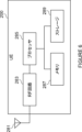
(2)ハードウェア構成
次に、図6を参照して、本開示の実施形態に係るUE200のハードウェア構成の例を説明する。図6を参照すると、UE200は、アンテナ281、RF回路283、プロセッサ285、メモリ287及びストレージ289を備える。
(2) Hardware Configuration Next, an example of a hardware configuration of the
アンテナ281は、信号を電波に変換し、当該電波を空間に放射する。また、アンテナ281は、空間における電波を受信し、当該電波を信号に変換する。アンテナ281は、送信アンテナ及び受信アンテナを含んでもよく、又は、送受信用の単一のアンテナであってもよい。アンテナ281は、指向性アンテナであってもよく、複数のアンテナ素子を含んでもよい。
The
RF回路283は、アンテナ281を介して送受信される信号のアナログ処理を行う。RF回路283は、高周波フィルタ、増幅器、変調器及びローパスフィルタ等を含んでもよい。
The
プロセッサ285は、アンテナ281及びRF回路283を介して送受信される信号のデジタル処理を行う。当該デジタル処理は、RANのプロトコルスタックの処理を含む。プロセッサ285は、複数のプロセッサを含んでもよく、又は、単一のプロセッサであってもよい。当該複数のプロセッサは、上記デジタル処理を行うベースバンドプロセッサと、他の処理を行う1つ以上のプロセッサとを含んでもよい。
The
メモリ287は、プロセッサ285により実行されるプログラム、当該プログラムに関するパラメータ、及び、その他の様々な情報を記憶する。メモリ287は、ROM、EPROM、EEPROM、RAM及びフラッシュメモリの少なくとも1つを含んでもよい。メモリ287の全部又は一部は、プロセッサ285内に含まれていてもよい。
ストレージ289は、様々な情報を記憶する。ストレージ289は、SSD及びHDDの少なくとも1つを含んでもよい。
無線通信部210は、アンテナ281及びRF回路283により実装されてもよい。記憶部220は、ストレージ289により実装されてもよい。処理部230は、プロセッサ285及びメモリ287により実装されてもよい。
The
処理部230は、プロセッサ285及びメモリ287を含むSoC(System on Chip)により実装されてもよい。当該SoCは、RF回路283を含んでもよく、無線通信部210も、当該SoCにより実装されてもよい。
The
以上のハードウェア構成を考慮すると、UE200は、プログラムを記憶するメモリ(即ち、メモリ287)と、当該プログラムを実行可能な1つ以上のプロセッサ(即ち、プロセッサ285)とを備えてもよく、当該1つ以上のプロセッサは、上記プログラムを実行して、処理部230の動作を行ってもよい。上記プログラムは、処理部230の動作をプロセッサに実行させるためのプログラムであってもよい。
Considering the above hardware configuration, UE200 may include a memory (i.e., memory 287) that stores a program, and one or more processors (i.e., processor 285) that can execute the program, and the one or more processors may execute the program to perform the operations of
<4.動作例>
図7を参照して、本開示の実施形態に係る基地局100及びUE200の動作の例を説明する。
<4. Operation example>
With reference to FIG. 7, an example of the operation of the
(1)状態遷移情報の送受信
UE200(情報取得部231)は、第1のモバイルネットワークから第2のモバイルネットワークへの切替時にUE200が遷移するRRC状態を示す状態遷移情報を取得する。UE200(通信処理部233)は、上記第2のモバイルネットワークにおけるUE200の登録に応じて、上記状態遷移情報を含むUE Assistance Informationメッセージを上記第1のモバイルネットワークの基地局100へ送信する。
(1) Transmission and Reception of State Transition Information The UE 200 (information acquisition unit 231) acquires state transition information indicating an RRC state to which the
基地局100(通信処理部143)は、上記状態遷移情報を含む上記UE Assistance InformationメッセージをUE200から受信する。基地局100(情報取得部141)は、上記状態遷移情報を取得する。
The base station 100 (communication processing unit 143) receives the UE Assistance Information message including the state transition information from the
上記状態遷移情報により示される上記RRC状態は、基地局100及びUE200の各々において、上記切替後のUE200のRRC状態として設定される。
The RRC state indicated by the state transition information is set in each of the
-RRC状態
上記RRC状態は、RRCアイドル状態又はRRC非アクティブ状態である。
- RRC State The RRC state is an RRC idle state or an RRC inactive state.
上述したように、上記RRC状態は、上記切替時にUE200が遷移するRRC状態である。UE200は、上記切替時に、自主的にRRC接続をリリースするので、上記RRC状態は、UE200によるRRC接続の自主的なリリースに応じてUE200が遷移するRRC状態とも言える。 As described above, the RRC state is the RRC state to which UE200 transitions at the time of the switching. Since UE200 autonomously releases the RRC connection at the time of the switching, the RRC state can also be said to be the RRC state to which UE200 transitions in response to the autonomous release of the RRC connection by UE200.
-状態遷移情報の送信の構成
例えば、基地局100(情報取得部141)は、上記状態遷移情報を送信するようにUE200を構成する構成情報を取得する。基地局100(通信処理部143)は、上記構成情報を含むRRC ReconfigurationメッセージをUE200へ送信する。例えば、基地局100は、UE200がマルチSIMのケイパビリティを有するので、上記構成情報をUE200へ送信する。
- Configuration of transmission of state transition information For example, the base station 100 (information acquisition unit 141) acquires configuration information for configuring the
例えば、UE200(通信処理部233)は、上記構成情報を含む上記RRC Reconfigurationメッセージを基地局100から受信する。UE200(情報取得部231)は、上記構成情報を取得する。例えば、UE200(通信処理部233)は、上記構成情報を受信することを条件に、上記状態遷移情報を基地局100へ送信する。
For example, UE200 (communication processing unit 233) receives the RRC Reconfiguration message including the above configuration information from
-送信タイミング
上述したように、UE200(通信処理部233)は、上記第2のモバイルネットワークにおけるUE200の登録に応じて、上記状態遷移情報を含む上記UE Assistance Informationメッセージを基地局100へ送信する。より具体的には、UE200(通信処理部233)は、上記登録の完了に応じて、上記UE Assistance Informationメッセージを基地局100へ送信する。
- Transmission Timing As described above, in response to the registration of the
例えば、UE200(通信処理部233)は、上記第2のモバイルネットワークへのアタッチ時に、又は、上記第2のモバイルネットワークにおける位置登録時に、上記登録を行う。 For example, UE200 (communication processing unit 233) performs the above registration when attaching to the second mobile network or when registering the location in the second mobile network.
例えば、UE200(通信処理部233)は、上記第2のモバイルネットワークにおける上記登録のための手続きとして、REGISTRATION REQUESTメッセージを基地局40を介してネットワークノード50へ送信し、REGISTRATION ACCEPTメッセージを基地局40を介してネットワークノード50から受信する。上記REGISTRATION REQUESTメッセージ及び上記REGISTRATION ACCEPTメッセージは、NAS(Non-Access Stratum)メッセージである。
For example, UE 200 (communication processing unit 233) transmits a REGISTRATION REQUEST message to network
以上のように、上記状態遷移情報が送受信される。これにより、例えば、UE200による上記第2のモバイルネットワークへの迅速な切替を無駄なシグナリングなしで確実に実現することが可能になる。より具体的には、上記状態遷移情報は、上記第2のモバイルネットワークにおける上記登録後に基地局100において必要になるので、上記状態遷移情報は、必要になってはじめて送信される。即ち、上記状態遷移情報は必要なしに送信されないので、無断なシグナリングが回避される。また、上記状態遷移情報は、上記第2のモバイルネットワークにおける上記登録に応じて基地局100へ送信されるので、基地局100は、上記第2のモバイルネットワークにおけるUE200へのページングの発生前に、上記状態遷移情報を取得できる。そのため、UE200は、上記第2のモバイルネットワークへの迅速な切替を確実に行うことができる。また、UE200は、UE ASSISTANCE INFORMATIONメッセージを使用することにより、上記第2のモバイルネットワークにおける上記登録に応じて自主的に上記状態遷移情報を基地局100へ送信することができる。
As described above, the state transition information is transmitted and received. This makes it possible, for example, to reliably realize rapid switching to the second mobile network by the
(2)ネットワークの切替
例えば、UE200(通信処理部233)は、上記切替の通知のためのメッセージを上記第1のモバイルネットワークへ送信する。
(2) Switching of Networks For example, the UE 200 (the communication processing unit 233) transmits a message for notifying the switching to the first mobile network.
-メッセージ
例えば、上記メッセージは、上記切替の通知のためのRRCメッセージである。この場合に、UE200(通信処理部233)は、上記メッセージを基地局100へ送信する。基地局100(通信処理部143)は、上記メッセージをUE200から受信する。
- Message For example, the message is an RRC message for notifying the switching. In this case, the UE 200 (communication processing unit 233) transmits the message to the
-RRC状態の遷移
例えば、UE200(通信処理部233)は、上記切替の通知のための上記メッセージに対応する確認応答(Acknowledge:ACK)の受信に応じて、UE200を上記RRC状態(例えば、RRCアイドル又はRRC非アクティブ)に遷移させる。例えば、当該ACKは、レイヤ2のプロトコルであるRLCレイヤのACKであってもよく、レイヤ2のプロトコルであるMACレイヤのHARQ(hybrid automatic repeat request)のACKであってもよい。これにより、例えば、上記メッセージの受信が最低限確認され、且つ、迅速な切替が行われる。
- Transition of RRC state For example, the UE 200 (communication processing unit 233) transitions the
一方、例えば、基地局100(通信処理部143)は、上記メッセージの受信に応じて、基地局100においてUE200を上記RRC状態に遷移させる。即ち、基地局100において維持されているUE200のRRC状態が、上記状態遷移情報により示される上記RRC状態となる。
On the other hand, for example, in response to receiving the message, the base station 100 (communication processing unit 143) transitions the
このような切替により、UE200は、上記第1のモバイルネットワークにおいてRRC接続状態であっても、上記第2のモバイルネットワークにおける通信を行うことが可能になる。また、上記状態遷移情報により、上記第1のネットワーク(とりわけ基地局100)とUE200との間でのRRC状態の不一致が抑制され得る。
By this switching, the
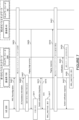
(3)処理の流れ
図7を参照して、本開示の実施形態に係る処理の例を説明する。
(3) Processing Flow An example of processing according to an embodiment of the present disclosure will be described with reference to FIG.
UE200と基地局100との間で、RRC Reconfiguration手続きが行われる(S401)。例えば、基地局100は、状態遷移情報を送信するようにUE200を構成する構成情報を含むRRC ReconfigurationメッセージをUE200へ送信する。
An RRC Reconfiguration procedure is performed between
UE200は、第2のモバイルネットワークにおける登録のための手続きを行う(S403)。 UE200 performs procedures for registration in the second mobile network (S403).
UE200は、上記登録に応じて、上記第1のモバイルネットワークから上記第2のモバイルネットワークへの切替時にUE200が遷移するRRC状態を示す状態遷移情報を含むUE Assistance Informationメッセージを基地局100へ送信する(S405)。基地局100は、当該UE Assistance Informationメッセージを受信し、上記状態遷移情報を取得する。UE200及び基地局100は、上記RRC状態を、ネットワークの切替後のUE200のRRC状態として設定する(S407)。例えば、上記RRC状態は、RRC非アクティブである。
In response to the registration, the
UE200は、ページングメッセージを基地局40から受信する(S409)。当該ページングメッセージは、UE200の識別情報と、対応する優先度の情報とを含む。例えば、当該情報は、高い優先度を示す。UE200は、上記第1のモバイルネットワークから上記第2のモバイルネットワークへの切替を判定する(S411)。例えば、UE200は、当該切替を行うと判定する。 UE200 receives a paging message from base station 40 (S409). The paging message includes identification information of UE200 and corresponding priority information. For example, the information indicates high priority. UE200 determines to switch from the first mobile network to the second mobile network (S411). For example, UE200 determines to perform the switch.
UE200は、上記切替の通知のためのメッセージを基地局100へ送信する(S413)。例えば、当該メッセージは、長時間スイッチングのためのRRCメッセージである。UE200は、上記メッセージに対応するACK(例えば、RLC ACK、又は、HARQ ACK)を受信し(S415)、上記RRC状態(例えば、RRC非アクティブ)に遷移する(S417)。
UE200 transmits a message to notify the
UE200は、ページング応答を基地局40へ送信する(S419)。その後、UE200は、上記第2のモバイルネットワークにおける通信を開始する(S421)。 UE200 transmits a paging response to base station 40 (S419). Then, UE200 starts communication in the second mobile network (S421).
基地局100は、UE200からの上記メッセージの受信(S413)に応じて、ネットワークノード300に上記切替を通知し(S423)、ネットワークノード300は、UE200とのデータの送受信を停止する(S425)。基地局100は、上記メッセージへの応答をUE200へ送信し(S427)、基地局100においてUE200をRRC非アクティブに遷移させる(S429)。
In response to receiving the message from UE 200 (S413),
とりわけ、ステップS417~S421の処理と、ステップS423~S429の処理とは、並列で行われてもよい。 In particular, the processes in steps S417 to S421 and the processes in steps S423 to S429 may be performed in parallel.
<5.変形例>
図8を参照して、本開示の実施形態に係る第1~第4の変形例を説明する。なお、これらの変形例の2つ以上が組み合わせられてもよい。
5. Modifications
First to fourth modified examples according to the embodiment of the present disclosure will be described with reference to Fig. 8. Note that two or more of these modified examples may be combined.
(1)第1の変形例
本開示の実施形態の上述した例では、UE200(通信処理部233)は、上記第1のモバイルネットワークから上記第2のモバイルネットワークへの上記切替の通知のためのメッセージを上記第1のモバイルネットワークへ送信する。上記メッセージは、上記切替の通知のためのRRCメッセージである。しかし、本開示の実施形態に係る上記メッセージは、この例に限定されない。
(1) First Modification In the above-described example of the embodiment of the present disclosure, the UE 200 (communication processing unit 233) transmits a message for notifying the switching from the first mobile network to the second mobile network to the first mobile network. The message is an RRC message for notifying the switching. However, the message according to the embodiment of the present disclosure is not limited to this example.
本開示の実施形態の第1の変形例では、上記メッセージは、上記切替の通知のためのNASメッセージであってもよい。この場合に、UE200(通信処理部233)は、上記第1のモバイルネットワークのコアネットワーク30内のネットワークノード300へ上記メッセージを送信してもよい。
In a first modified example of the embodiment of the present disclosure, the message may be a NAS message for notifying the switching. In this case, the UE 200 (communication processing unit 233) may transmit the message to a
-処理の流れ
図8を参照して、本開示の実施形態の第1の変形例に係る処理の例を説明する。なお、ここでは、図8の例と図7の例との相違点のみを説明し、重複する説明を省略する。
- Processing flow An example of processing according to the first modified example of the embodiment of the present disclosure will be described with reference to Fig. 8. Note that only the differences between the example of Fig. 8 and the example of Fig. 7 will be described here, and overlapping descriptions will be omitted.
UE200は、上記切替の通知のためのメッセージを、基地局100を介してネットワークノード300へ送信する(S513)。例えば、当該メッセージは、長時間スイッチングのためのNASメッセージである。
ネットワークノード300は、UE200からの上記メッセージの受信(S513)に応じて、UE200とのデータの送受信を停止し(S523)、上記メッセージへの応答をUE200へ送信する(S525)。さらに、ネットワークノード300は、基地局100に上記切替を通知する(S527)。
In response to receiving the above message from UE 200 (S513),
基地局100は、RRC ReleaseメッセージをUE200へ送信し(S529)、基地局100においてUE200をRRC非アクティブに遷移させる(S531)。
The
とりわけ、ステップS417~S421の処理と、ステップS523~S531の処理とは、並列で行われてもよい。 In particular, the processes in steps S417 to S421 and the processes in steps S523 to S531 may be performed in parallel.
(2)第2の変形例
本開示の実施形態の上述した例では、UE200(通信処理部233)は、上記第2のモバイルネットワークにおけるUE200の上記登録に応じて、上記状態遷移情報を含む上記UE Assistance Informationメッセージを基地局100へ送信する。しかし、本開示の実施形態に係る上記状態遷移情報の送信は、この例のみに限定されない。
(2) Second Modification In the above-described example of the embodiment of the present disclosure, the UE 200 (the communication processing unit 233) transmits the UE Assistance Information message including the state transition information to the
本開示の実施形態の第2の変形例では、基地局100(通信処理部143)は、上記UE Assistance Informationメッセージの送信のための複数の契機のうちの少なくとも1つを示す契機情報をUE200へ送信してもよい。一例として、基地局100(通信処理部143)は、当該契機情報を含むRRC ReconfigurationメッセージをUE200へ送信してもよい。
In a second modified example of the embodiment of the present disclosure, the base station 100 (communication processing unit 143) may transmit trigger information indicating at least one of multiple triggers for transmitting the UE Assistance Information message to the
UE200(通信処理部233)は、上記契機情報を基地局100から受信してもよい。一例として、UE200(通信処理部233)は、上記契機情報を含むRRC Reconfigurationメッセージを基地局100から受信してもよい。UE200(通信処理部233)は、上記契機情報により示される少なくとも1つの契機に応じて、上記UE Assistance Informationメッセージを基地局100へ送信してもよい。
UE200 (communication processing unit 233) may receive the trigger information from
上記複数の契機は、上記第2のモバイルネットワークにおけるUE200の上記登録を含んでもよい。 The multiple triggers may include the registration of UE200 in the second mobile network.
これにより、例えば、上記第2のモバイルネットワークにおける登録以外の契機でも、UE200が上記状態遷移情報を基地局100へ送信することが可能になる。
This allows the
(3)第3の変形例
本開示の実施形態の上述した例では、上記第1のモバイルネットワークから上記第2のモバイルネットワークへの切替の際に、UE200は、上記状態遷移情報により示されるRRC状態に遷移する。しかし、本開示の実施形態に係る遷移は、この例のみに限定されない。
(3) Third Modification In the above-described example of the embodiment of the present disclosure, when switching from the first mobile network to the second mobile network, the
本開示の実施形態の第3の変形例では、UE200が、上記状態遷移情報を基地局100へ送信しない場合には、UE200は、上記切替の際に、RRCアイドルに遷移してもよい。これにより、例えば、上記状態遷移情報の送信がない場合でも、上記第2のネットワークへの迅速な切替が可能になる。
In a third modification of the embodiment of the present disclosure, the
(4)第4の変形例
本開示の実施形態の上述した例では、システム1は、5G又はNRのTSに準拠したシステムである。しかし、本開示の実施形態に係るシステム1は、この例に限定されない。
(4) Fourth Modification In the above-described example of the embodiment of the present disclosure, the
本開示の実施形態の第4の変形例では、システム1は、3GPPの他のTSに準拠したシステムであってもよい。一例として、システム1は、LTE(Long Term Evolution)、LTE-A(LTE Advanced)又は4GのTSに準拠したシステムであってもよく、基地局100は、eNB(evolved Node B)であってもよい。あるいは、基地局100は、ng-eNBであってもよい。別の例として、システム1は、3GのTSに準拠したシステムであってもよく、基地局100は、NodeBであってもよい。さらに別の例として、システム1は、次世代(例えば、6G)のTSに準拠したシステムであってもよい。
In a fourth variant of the embodiment of the present disclosure, the
あるいは、システム1は、移動体通信についての他の標準化団体のTSに準拠したシステムであってもよい。
Alternatively,
以上、本開示の実施形態を説明したが、本開示は当該実施形態に限定されるものではない。当該実施形態は例示にすぎないということ、及び、本開示のスコープ及び精神から逸脱することなく様々な変形が可能であるということは、当業者に理解されるであろう。 Although the embodiments of the present disclosure have been described above, the present disclosure is not limited to these embodiments. It will be understood by those skilled in the art that the embodiments are merely examples, and that various modifications are possible without departing from the scope and spirit of the present disclosure.
例えば、本明細書に記載されている処理におけるステップは、必ずしもフローチャート又はシーケンス図に記載された順序に沿って時系列に実行されなくてよい。例えば、処理におけるステップは、フローチャート又はシーケンス図として記載した順序と異なる順序で実行されても、並列的に実行されてもよい。また、処理におけるステップの一部が削除されてもよく、さらなるステップが処理に追加されてもよい。 For example, the steps in the processes described herein do not necessarily have to be performed chronologically in the order depicted in the flowcharts or sequence diagrams. For example, the steps in the processes may be performed in an order different from that depicted in the flowcharts or sequence diagrams, or may be performed in parallel. Also, some of the steps in the processes may be deleted, and additional steps may be added to the processes.
例えば、本明細書において説明した装置の1つ以上の構成要素の動作を含む方法が提供されてもよく、上記構成要素の動作をコンピュータに実行させるためのプログラムが提供されてもよい。また、当該プログラムを記録したコンピュータに読み取り可能な非遷移的実体的記録媒体が提供されてもよい。当然ながら、このような方法、プログラム、及びコンピュータに読み取り可能な非遷移的実体的記録媒体(non-transitory tangible computer-readable storage medium)も、本開示に含まれる。 For example, a method including the operation of one or more components of the apparatus described in this specification may be provided, and a program for causing a computer to execute the operation of the components may be provided. Also, a non-transitory tangible computer-readable storage medium having the program recorded thereon may be provided. Naturally, such methods, programs, and non-transitory tangible computer-readable storage medium are also included in the present disclosure.
例えば、本開示において、ユーザ機器(UE)は、移動局(mobile station)、移動端末、移動装置、移動ユニット、加入者局(subscriber station)、加入者端末、加入者装置、加入者ユニット、ワイヤレス局、ワイヤレス端末、ワイヤレス装置、ワイヤレスユニット、リモート局、リモート端末、リモート装置、又はリモートユニット等の別の名称で呼ばれてもよい。 For example, in this disclosure, user equipment (UE) may be referred to by other names such as a mobile station, mobile terminal, mobile device, mobile unit, subscriber station, subscriber terminal, subscriber device, subscriber unit, wireless station, wireless terminal, wireless device, wireless unit, remote station, remote terminal, remote device, or remote unit.
例えば、本開示において、「送信する(transmit)」は、送信に使用されるプロトコルスタック内の少なくとも1つのレイヤの処理を行うことを意味してもよく、又は、無線又は有線で信号を物理的に送信することを意味してもよい。あるいは、「送信する」は、上記少なくとも1つのレイヤの処理を行うことと、無線又は有線で信号を物理的に送信することとの組合せを意味してもよい。同様に、「受信する(receive)」は、受信に使用されるプロトコルスタック内の少なくとも1つのレイヤの処理を行うことを意味してもよく、又は、無線又は有線で信号を物理的に受信することを意味してもよい。あるいは、「受信する」は、上記少なくとも1つのレイヤの処理を行うことと、無線又は有線で信号を物理的に受信することとの組合せを意味してもよい。上記少なくとも1つのレイヤは、少なくとも1つのプロトコルと言い換えられてもよい。 For example, in the present disclosure, "transmit" may mean performing processing of at least one layer in a protocol stack used for transmission, or may mean physically transmitting a signal wirelessly or via a wire. Alternatively, "transmit" may mean a combination of performing processing of at least one layer and physically transmitting a signal wirelessly or via a wire. Similarly, "receive" may mean performing processing of at least one layer in a protocol stack used for reception, or may mean physically receiving a signal wirelessly or via a wire. Alternatively, "receive" may mean a combination of performing processing of at least one layer and physically receiving a signal wirelessly or via a wire. The at least one layer may be rephrased as at least one protocol.
例えば、本開示において、「取得する(obtain/acquire)」は、記憶されている情報の中から情報を取得することを意味してもよく、他のノードから受信した情報の中から情報を取得することを意味してもよく、又は、情報を生成することにより当該情報を取得することを意味してもよい。 For example, in this disclosure, "obtain/acquire" may mean obtaining information from stored information, obtaining information from information received from other nodes, or obtaining information by generating the information.
例えば、本開示において、「~を含む(include)」及び「~を備える(comprise)」は、列挙する項目のみを含むことを意味せず、列挙する項目のみを含んでもよいし、列挙する項目に加えてさらなる項目を含んでもよいことを意味する。 For example, in this disclosure, "include" and "comprise" do not mean including only the items listed, but may include only the items listed, or may include additional items in addition to the items listed.
例えば、本開示において、「又は(or)」は、排他的論理和を意味せず、論理和を意味する。 For example, in this disclosure, "or" does not mean exclusive or, but means logical or.
なお、上述した実施形態に含まれる技術的特徴は、以下のような特徴として表現されてもよい。当然ながら、本開示は以下のような特徴に限定されない。 The technical features included in the above-described embodiment may be expressed as the following features. Of course, the present disclosure is not limited to the following features.
(特徴1)
ユーザ機器(200)であって、
第1のモバイルネットワークから第2のモバイルネットワークへの切替時に前記ユーザ機器が遷移するRRC(Radio Resource Control)状態を示す状態遷移情報を取得する情報取得部(231)と、
前記第2のモバイルネットワークにおける前記ユーザ機器の登録に応じて、前記状態遷移情報を含むUE Assistance Informationメッセージを前記第1のモバイルネットワークの基地局(100)へ送信する通信処理部(233)と、
を備えるユーザ機器。
(Feature 1)
A user equipment (200),
An information acquisition unit (231) that acquires state transition information indicating an RRC (Radio Resource Control) state to which the user equipment transitions when switching from a first mobile network to a second mobile network;
a communication processing unit (233) for transmitting a UE Assistance Information message including the state transition information to a base station (100) of the first mobile network in response to registration of the user equipment in the second mobile network;
A user equipment comprising:
(特徴2)
前記RRC状態は、RRCアイドル状態又はRRC非アクティブ状態である、特徴1に記載のユーザ機器。
(Feature 2)
2. The user equipment of
(特徴3)
前記通信処理部は、前記状態遷移情報を送信するように前記ユーザ機器を構成する構成情報を含むRRC Reconfigurationメッセージを前記基地局から受信する、特徴1又は2に記載のユーザ機器。
(Feature 3)
3. The user equipment according to
(特徴4)
前記通信処理部は、前記切替の通知のためのメッセージを前記第1のモバイルネットワークへ送信する、特徴1~3のいずれか1項に記載のユーザ機器。
(Feature 4)
The user equipment according to any one of
(特徴5)
前記メッセージは、前記切替の通知のためのRRCメッセージであり、
前記通信処理部は、前記メッセージを前記基地局へ送信する、
特徴4に記載のユーザ機器。
(Feature 5)
The message is an RRC message for notifying the switching,
The communication processing unit transmits the message to the base station.
5. The user equipment according to feature 4.
(特徴6)
前記メッセージは、前記切替の通知のためのNAS(Non-Access Stratum)メッセージであり、
前記通信処理部は、前記第1のモバイルネットワークのコアネットワーク(30)内のネットワークノード(300)へ前記メッセージを送信する、
特徴4に記載のユーザ機器。
(Feature 6)
The message is a Non-Access Stratum (NAS) message for notifying the switching,
The communication processing unit transmits the message to a network node (300) in a core network (30) of the first mobile network.
5. The user equipment according to feature 4.
(特徴7)
前記切替の通知のための前記メッセージに対応する確認応答(Acknowledge)の受信に応じて、前記ユーザ機器を前記RRC状態に遷移させる制御部(235)、をさらに備える、特徴4~6のいずれか1項に記載のユーザ機器。
(Feature 7)
In response to reception of an acknowledgement (Acknowledge) corresponding to the message for notifying of the switching, the user equipment transitions to the RRC state.
(特徴8)
前記通信処理部は、前記UE Assistance Informationメッセージの送信のための複数の契機のうちの少なくとも1つを示す契機情報を前記基地局から受信し、
前記通信処理部は、前記契機情報により示される少なくとも1つの契機に応じて、前記UE Assistance Informationメッセージを前記基地局へ送信し、
前記複数の契機は、前記第2のモバイルネットワークにおける前記ユーザ機器の前記登録を含む、
特徴1~7のいずれか1項に記載のユーザ機器。
(Feature 8)
The communication processing unit receives, from the base station, trigger information indicating at least one of a plurality of triggers for transmitting the UE Assistance Information message;
The communication processing unit transmits the UE Assistance Information message to the base station in response to at least one trigger indicated by the trigger information;
the plurality of triggers including the registration of the user equipment in the second mobile network;
8. The user equipment according to any one of
(特徴9)
前記ユーザ機器は、2つ以上のSIM(Subscriber Identity Module)カードを搭載可能であり、
前記第1のモバイルネットワークは、前記2つ以上のSIMカードのうちの1つに対応し、
前記第2のモバイルネットワークは、前記2つ以上のSIMカードのうちの他の1つに対応する、
特徴1~8のいずれか1項に記載のユーザ機器。
(Feature 9)
The user equipment can be equipped with two or more SIM (Subscriber Identity Module) cards;
the first mobile network corresponds to one of the two or more SIM cards;
the second mobile network corresponds to another one of the two or more SIM cards;
9. The user equipment according to any one of
(特徴10)
第1のモバイルネットワークの基地局(100)であって、
前記第1のモバイルネットワークから第2のモバイルネットワークへの切替時にユーザ機器(200)が遷移するRRC(Radio Resource Control)状態を示す状態遷移情報を含むUE Assistance Informationメッセージであって、前記第2のモバイルネットワークにおける前記ユーザ機器の登録に応じて前記ユーザ機器により送信される当該UE Assistance Informationメッセージを、前記ユーザ機器から受信する通信処理部(143)と、
前記状態遷移情報を取得する情報取得部(141)と、
を備える基地局。
(Feature 10)
A base station (100) of a first mobile network, comprising:
a communication processing unit (143) for receiving, from the user equipment, a UE Assistance Information message including state transition information indicating an RRC (Radio Resource Control) state to which the user equipment (200) transitions when switching from the first mobile network to a second mobile network, the UE Assistance Information message being transmitted by the user equipment in response to registration of the user equipment in the second mobile network;
An information acquisition unit (141) for acquiring the state transition information;
A base station comprising:
(特徴11)
前記通信処理部は、前記状態遷移情報を送信するように前記ユーザ機器を構成する構成情報を含むRRC Reconfigurationメッセージを前記ユーザ機器へ送信する、特徴10に記載の基地局。
(Feature 11)
11. The base station according to
(特徴12)
前記通信処理部は、前記切替の通知のためのメッセージを前記ユーザ機器から受信し、
前記切替の通知のための前記メッセージの受信に応じて、前記基地局において前記ユーザ機器を前記RRC状態に遷移させる制御部(145)、をさらに備える、
特徴10又は11に記載の基地局。
(Feature 12)
The communication processing unit receives a message for notifying the switching from the user equipment,
A control unit (145) for transitioning the user equipment to the RRC state in the base station in response to receiving the message for notifying the switching.
12. The base station according to feature 10 or 11.
(特徴13)
前記通信処理部は、前記UE Assistance Informationメッセージの送信のための複数の契機のうちの少なくとも1つを示す契機情報を前記ユーザ機器へ送信し、
前記複数の契機は、前記第2のモバイルネットワークにおける前記ユーザ機器の前記登録を含む、
特徴10~12のいずれか1項に記載の基地局。
(Feature 13)
The communication processing unit transmits, to the user equipment, trigger information indicating at least one of a plurality of triggers for transmitting the UE Assistance Information message;
the plurality of triggers including the registration of the user equipment in the second mobile network.
13. The base station according to any one of
(特徴14)
ユーザ機器(200)により行われる方法であって、
第1のモバイルネットワークから第2のモバイルネットワークへの切替時に前記ユーザ機器が遷移するRRC(Radio Resource Control)状態を示す状態遷移情報を取得することと、
前記第2のモバイルネットワークにおける前記ユーザ機器の登録に応じて、前記状態遷移情報を含むUE Assistance Informationメッセージを前記第1のモバイルネットワークの基地局(100)へ送信することと、
を含む方法。
(Feature 14)
A method performed by a user equipment (200), comprising:
acquiring state transition information indicating a Radio Resource Control (RRC) state to which the user equipment transitions when switching from a first mobile network to a second mobile network;
sending a UE Assistance Information message to a base station (100) of the first mobile network, the UE Assistance Information message including the state transition information in response to registration of the user equipment in the second mobile network;
The method includes:
(特徴15)
第1のモバイルネットワークの基地局(100)により行われる方法であって、
前記第1のモバイルネットワークから第2のモバイルネットワークへの切替時にユーザ機器(200)が遷移するRRC(Radio Resource Control)状態を示す状態遷移情報を含むUE Assistance Informationメッセージであって、前記第2のモバイルネットワークにおける前記ユーザ機器の登録に応じて前記ユーザ機器により送信される当該UE Assistance Informationメッセージを、前記ユーザ機器から受信することと、
前記状態遷移情報を取得することと、
を含む方法。
(Feature 15)
A method performed by a base station (100) of a first mobile network, comprising:
receiving, from the user equipment, a UE Assistance Information message including state transition information indicating a Radio Resource Control (RRC) state to which the user equipment (200) transitions when switching from the first mobile network to a second mobile network, the UE Assistance Information message being transmitted by the user equipment in response to registration of the user equipment in the second mobile network;
acquiring the state transition information;
The method includes:
(特徴16)
第1のモバイルネットワークから第2のモバイルネットワークへの切替時にユーザ機器(200)が遷移するRRC(Radio Resource Control)状態を示す状態遷移情報を取得することと、
前記第2のモバイルネットワークにおける前記ユーザ機器の登録に応じて、前記状態遷移情報を含むUE Assistance Informationメッセージを前記第1のモバイルネットワークの基地局(100)へ送信することと、
をコンピュータに実行させるプログラム。
(Feature 16)
Obtaining state transition information indicating a Radio Resource Control (RRC) state to which a user equipment (200) transitions when switching from a first mobile network to a second mobile network;
sending a UE Assistance Information message to a base station (100) of the first mobile network, the UE Assistance Information message including the state transition information in response to registration of the user equipment in the second mobile network;
A program that causes a computer to execute the following.
(特徴17)
第1のモバイルネットワークから第2のモバイルネットワークへの切替時にユーザ機器(200)が遷移するRRC(Radio Resource Control)状態を示す状態遷移情報を含むUE Assistance Informationメッセージであって、前記第2のモバイルネットワークにおける前記ユーザ機器の登録に応じて前記ユーザ機器により送信される当該UE Assistance Informationメッセージを、前記ユーザ機器から受信することと、
前記状態遷移情報を取得することと、
をコンピュータに実行させるプログラム。
(Feature 17)
receiving, from the user equipment, a UE Assistance Information message including state transition information indicating a Radio Resource Control (RRC) state to which the user equipment (200) transitions when switching from a first mobile network to a second mobile network, the UE Assistance Information message being transmitted by the user equipment in response to registration of the user equipment in the second mobile network;
acquiring the state transition information;
A program that causes a computer to execute the following.
(特徴18)
第1のモバイルネットワークから第2のモバイルネットワークへの切替時にユーザ機器(200)が遷移するRRC(Radio Resource Control)状態を示す状態遷移情報を取得することと、
前記第2のモバイルネットワークにおける前記ユーザ機器の登録に応じて、前記状態遷移情報を含むUE Assistance Informationメッセージを前記第1のモバイルネットワークの基地局(100)へ送信することと、
をコンピュータに実行させるプログラムを記録したコンピュータに読み取り可能な非遷移的実体的記録媒体。
(Feature 18)
Obtaining state transition information indicating a Radio Resource Control (RRC) state to which a user equipment (200) transitions when switching from a first mobile network to a second mobile network;
sending a UE Assistance Information message to a base station (100) of the first mobile network, the UE Assistance Information message including the state transition information in response to registration of the user equipment in the second mobile network;
A non-transitory tangible recording medium readable by a computer on which a program for causing a computer to execute the above is recorded.
(特徴19)
第1のモバイルネットワークから第2のモバイルネットワークへの切替時にユーザ機器(200)が遷移するRRC(Radio Resource Control)状態を示す状態遷移情報を含むUE Assistance Informationメッセージであって、前記第2のモバイルネットワークにおける前記ユーザ機器の登録に応じて前記ユーザ機器により送信される当該UE Assistance Informationメッセージを、前記ユーザ機器から受信することと、
前記状態遷移情報を取得することと、
をコンピュータに実行させるプログラムを記録したコンピュータに読み取り可能な非遷移的実体的記録媒体。
(Feature 19)
receiving, from the user equipment, a UE Assistance Information message including state transition information indicating a Radio Resource Control (RRC) state to which the user equipment (200) transitions when switching from a first mobile network to a second mobile network, the UE Assistance Information message being transmitted by the user equipment in response to registration of the user equipment in the second mobile network;
acquiring the state transition information;
A non-transitory tangible recording medium readable by a computer on which a program for causing a computer to execute the above is recorded.
1 システム
10 カバレッジエリア
30 コアネットワーク
40 基地局
50 ネットワークノード
100 基地局
141 情報取得部
143 通信処理部
145 制御部
200 ユーザ機器
231 情報取得部
233 通信処理部
235 制御部
300 ネットワークノード
REFERENCE SIGNS
Claims (9)
前記装置のRRC(Radio Resource Control)状態であって、RRCアイドル状態又はRRC非アクティブ状態である前記RRC状態を示すために用いられる第2の情報を含むUE Assistance Informationメッセージを送信するように前記装置を構成する第1の情報を含むRRC Reconfigurationメッセージを第1のネットワークから受信する通信処理部(233)
を備え、
前記通信処理部は、前記第1のネットワークにおいてRRCコネクテッド状態での前記第1のネットワークから第2のネットワークへの切替の前に、前記第1の情報に基づいて、前記第2の情報を含む前記UE Assistance Informationメッセージを前記第1のネットワークへ送信する、
装置。 An apparatus (200), comprising:
a communication processing unit (233) for receiving from a first network an RRC Reconfiguration message including first information for configuring the device to transmit a UE Assistance Information message including second information used to indicate an RRC state of the device, the RRC state being an RRC idle state or an RRC inactive state;
Equipped with
The communication processing unit transmits the UE Assistance Information message including the second information to the first network based on the first information before switching from the first network to the second network in an RRC connected state in the first network.
Device.
前記第2のネットワークは、前記装置の前記2つ以上のSIMのうちの他の1つに対応するネットワークである、
請求項2に記載の装置。 the first network is a network corresponding to one of two or more SIMs of the device;
the second network is a network corresponding to another of the two or more SIMs of the device;
3. The apparatus of claim 2 .
装置のRRC(Radio Resource Control)状態であって、RRCアイドル状態又はRRC非アクティブ状態である前記RRC状態を示すために用いられる第2の情報を含むUE Assistance Informationメッセージを送信するように前記装置を構成する第1の情報を含むRRC Reconfigurationメッセージを前記装置へ送信する通信処理部(143)
を備え、
前記通信処理部は、前記第1のネットワークにおいてRRCコネクテッド状態での前記第1のネットワークから第2のネットワークへの切替の前に前記第1の情報に基づいて送信される前記UE Assistance Informationメッセージであって、前記第2の情報を含む当該UE Assistance Informationメッセージを、前記装置から受信する、
基地局。 A base station (100) in a first network,
a communication processing unit (143) for transmitting to the device an RRC Reconfiguration message including first information for configuring the device to transmit a UE Assistance Information message including second information used to indicate an RRC state of the device, the RRC state being an RRC idle state or an RRC inactive state;
Equipped with
The communication processing unit receives from the device the UE Assistance Information message, the UE Assistance Information message including the second information, the UE Assistance Information message being transmitted based on the first information before switching from the first network to the second network in an RRC connected state in the first network.
Base station.
前記第2のネットワークは、前記装置の前記2つ以上のSIMのうちの他の1つに対応するネットワークである、
請求項5に記載の基地局。 the first network is a network corresponding to one of two or more SIMs of the device;
the second network is a network corresponding to another of the two or more SIMs of the device;
The base station according to claim 5 .
前記装置のRRC(Radio Resource Control)状態であって、RRCアイドル状態又はRRC非アクティブ状態である前記RRC状態を示すために用いられる第2の情報を含むUE Assistance Informationメッセージを送信するように前記装置を構成する第1の情報を含むRRC Reconfigurationメッセージを第1のネットワークから受信することと、
前記第1のネットワークにおいてRRCコネクテッド状態での前記第1のネットワークから第2のネットワークへの切替の前に、前記第1の情報に基づいて、前記第2の情報を含む前記UE Assistance Informationメッセージを前記第1のネットワークへ送信することと、
を含む方法。 A method performed by an apparatus (200), comprising:
receiving from a first network a Radio Resource Control (RRC) Reconfiguration message including first information for configuring the device to transmit a UE Assistance Information message including second information used to indicate a Radio Resource Control (RRC) state of the device, the RRC state being an RRC idle state or an RRC inactive state;
sending, to the first network, a UE Assistance Information message including the second information based on the first information, before switching from the first network to a second network in an RRC connected state in the first network;
The method includes:
前記第2のネットワークは、前記装置の前記2つ以上のSIMのうちの他の1つに対応するネットワークである、
請求項8に記載の方法。
the first network is a network corresponding to one of two or more SIMs of the device;
the second network is a network corresponding to another of the two or more SIMs of the device;
The method according to claim 8 .
Priority Applications (6)
| Application Number | Priority Date | Filing Date | Title |
|---|---|---|---|
| JP2021048512A JP7689433B2 (en) | 2021-03-23 | 2021-03-23 | User equipment, base station and method |
| BR112023019177A BR112023019177A2 (en) | 2021-03-23 | 2022-03-16 | DEVICE AND METHOD |
| CN202280024092.XA CN117099411A (en) | 2021-03-23 | 2022-03-16 | Device and method |
| EP22775361.3A EP4319306A4 (en) | 2021-03-23 | 2022-03-16 | DEVICE AND METHOD |
| PCT/JP2022/012078 WO2022202573A1 (en) | 2021-03-23 | 2022-03-16 | Device and method |
| US18/471,394 US20240015836A1 (en) | 2021-03-23 | 2023-09-21 | Apparatus, base station and method |
Applications Claiming Priority (1)
| Application Number | Priority Date | Filing Date | Title |
|---|---|---|---|
| JP2021048512A JP7689433B2 (en) | 2021-03-23 | 2021-03-23 | User equipment, base station and method |
Publications (3)
| Publication Number | Publication Date |
|---|---|
| JP2022147321A JP2022147321A (en) | 2022-10-06 |
| JP2022147321A5 JP2022147321A5 (en) | 2024-02-27 |
| JP7689433B2 true JP7689433B2 (en) | 2025-06-06 |
Family
ID=83397176
Family Applications (1)
| Application Number | Title | Priority Date | Filing Date |
|---|---|---|---|
| JP2021048512A Active JP7689433B2 (en) | 2021-03-23 | 2021-03-23 | User equipment, base station and method |
Country Status (6)
| Country | Link |
|---|---|
| US (1) | US20240015836A1 (en) |
| EP (1) | EP4319306A4 (en) |
| JP (1) | JP7689433B2 (en) |
| CN (1) | CN117099411A (en) |
| BR (1) | BR112023019177A2 (en) |
| WO (1) | WO2022202573A1 (en) |
Families Citing this family (1)
| Publication number | Priority date | Publication date | Assignee | Title |
|---|---|---|---|---|
| US20230362625A1 (en) * | 2022-05-09 | 2023-11-09 | Qualcomm Incorporated | Updated artificial intelligence or machine learning capabilities reporting |
Citations (3)
| Publication number | Priority date | Publication date | Assignee | Title |
|---|---|---|---|---|
| WO2013047835A1 (en) | 2011-09-30 | 2013-04-04 | 日本電気株式会社 | Wireless communication system, wireless terminal, wireless station, network device, and information collection method |
| JP2014082799A (en) | 2012-01-05 | 2014-05-08 | Kotatsu Kokusai Denshi Kofun Yugenkoshi | Power saving method and related communication device |
| US20200260311A1 (en) | 2019-02-13 | 2020-08-13 | Samsung Electronics Co., Ltd. | Method and apparatus for supporting carrier aggregation in wireless communication system |
Family Cites Families (1)
| Publication number | Priority date | Publication date | Assignee | Title |
|---|---|---|---|---|
| JP7392343B2 (en) | 2019-09-19 | 2023-12-06 | 株式会社リコー | Display control device, display control system, display control method, and program |
-
2021
- 2021-03-23 JP JP2021048512A patent/JP7689433B2/en active Active
-
2022
- 2022-03-16 EP EP22775361.3A patent/EP4319306A4/en active Pending
- 2022-03-16 WO PCT/JP2022/012078 patent/WO2022202573A1/en not_active Ceased
- 2022-03-16 BR BR112023019177A patent/BR112023019177A2/en unknown
- 2022-03-16 CN CN202280024092.XA patent/CN117099411A/en active Pending
-
2023
- 2023-09-21 US US18/471,394 patent/US20240015836A1/en active Pending
Patent Citations (3)
| Publication number | Priority date | Publication date | Assignee | Title |
|---|---|---|---|---|
| WO2013047835A1 (en) | 2011-09-30 | 2013-04-04 | 日本電気株式会社 | Wireless communication system, wireless terminal, wireless station, network device, and information collection method |
| JP2014082799A (en) | 2012-01-05 | 2014-05-08 | Kotatsu Kokusai Denshi Kofun Yugenkoshi | Power saving method and related communication device |
| US20200260311A1 (en) | 2019-02-13 | 2020-08-13 | Samsung Electronics Co., Ltd. | Method and apparatus for supporting carrier aggregation in wireless communication system |
Non-Patent Citations (3)
| Title |
|---|
| Apple Inc,Methods for MUSIM Network Switching [online],3GPP TSG-RAN WG2 Meeting #113e R2-2100850, [検索日 2022.06.02],インターネット <URL: https://www.3gpp.org/ftp/TSG_RAN/WG2_RL2/TSGR2_113-e/Docs/R2-2100850.zip>,2021年01月15日 |
| vivo,[AT113-e][242][NR][Multi-SIM] NAS vs. RRC signalling for paging collision and network switching (vivo),3GPP TSG-RAN WG2 Meeting #113-e R2-2101981, [検索日 2022.06.02],インターネット <URL: https:// www.3gpp.org/ftp/TSG_RAN/WG2_RL2/TSGR2_113-e/Docs/R2-2101981.zip>,2021年02月10日 |
| vivo,[post112-e][256][Multi-SIM] Network switching details (vivo) [online],3GPP TSG-RAN WG2 Meeting #113-e R2-2100474, [検索日 2024.11.26],インターネット <URL: https://www.3gpp.org/ftp/TSG_RAN/WG2_RL2/TSGR2_113-e/Docs/R2-2100474.zip>,2021年01月15日 |
Also Published As
| Publication number | Publication date |
|---|---|
| US20240015836A1 (en) | 2024-01-11 |
| EP4319306A4 (en) | 2024-10-02 |
| CN117099411A (en) | 2023-11-21 |
| BR112023019177A2 (en) | 2023-11-28 |
| WO2022202573A1 (en) | 2022-09-29 |
| EP4319306A1 (en) | 2024-02-07 |
| JP2022147321A (en) | 2022-10-06 |
Similar Documents
| Publication | Publication Date | Title |
|---|---|---|
| RU2767981C2 (en) | Information processing method and corresponding device | |
| CN111149419B (en) | Method and apparatus for NR PDCP reservation upon RRC resumption/pause | |
| CN107708104B (en) | Method and device for changing secondary base station | |
| US12245316B2 (en) | Resuming SCG, synchronization aspects | |
| KR102779014B1 (en) | Handover to Dual Connectivity | |
| US20230354297A1 (en) | User equipment, base station and method | |
| US10827403B2 (en) | Data transmission method, user equipment, base station, and system | |
| JP7689433B2 (en) | User equipment, base station and method | |
| CN106060850B (en) | Voice scheduling method and device | |
| US12193090B2 (en) | First base station, second base station, method, program, and recording medium | |
| US20230354265A1 (en) | User equipment, network node, and base station | |
| WO2022202574A1 (en) | Device and method | |
| JP7692045B2 (en) | Apparatus and method | |
| CN118251928A (en) | First device, second device, and method | |
| CN117204117A (en) | Methods, devices and computer storage media for communications | |
| JP7667864B2 (en) | Apparatus and method | |
| US20230354264A1 (en) | Base station, user equipment, and network node | |
| US12543233B2 (en) | Wireless communication apparatus, wireless communication system, and processing method | |
| US20240090070A1 (en) | Communication apparatus, and communication method | |
| WO2024019062A1 (en) | Communication device, base station, and communication method | |
| CN119654910A (en) | Pre-configured mobility with handover preparation information at DU | |
| WO2022153747A1 (en) | User device, base station, and network node | |
| CN117796040A (en) | Device and method |
Legal Events
| Date | Code | Title | Description |
|---|---|---|---|
| A711 | Notification of change in applicant |
Free format text: JAPANESE INTERMEDIATE CODE: A711 Effective date: 20221207 |
|
| A521 | Request for written amendment filed |
Free format text: JAPANESE INTERMEDIATE CODE: A523 Effective date: 20240216 |
|
| A621 | Written request for application examination |
Free format text: JAPANESE INTERMEDIATE CODE: A621 Effective date: 20240216 |
|
| A131 | Notification of reasons for refusal |
Free format text: JAPANESE INTERMEDIATE CODE: A131 Effective date: 20241203 |
|
| A521 | Request for written amendment filed |
Free format text: JAPANESE INTERMEDIATE CODE: A523 Effective date: 20250122 |
|
| TRDD | Decision of grant or rejection written | ||
| A01 | Written decision to grant a patent or to grant a registration (utility model) |
Free format text: JAPANESE INTERMEDIATE CODE: A01 Effective date: 20250430 |
|
| A61 | First payment of annual fees (during grant procedure) |
Free format text: JAPANESE INTERMEDIATE CODE: A61 Effective date: 20250527 |
|
| R150 | Certificate of patent or registration of utility model |
Ref document number: 7689433 Country of ref document: JP Free format text: JAPANESE INTERMEDIATE CODE: R150 |