JP7686898B1 - Combustion System - Google Patents
Combustion System Download PDFInfo
- Publication number
- JP7686898B1 JP7686898B1 JP2025025582A JP2025025582A JP7686898B1 JP 7686898 B1 JP7686898 B1 JP 7686898B1 JP 2025025582 A JP2025025582 A JP 2025025582A JP 2025025582 A JP2025025582 A JP 2025025582A JP 7686898 B1 JP7686898 B1 JP 7686898B1
- Authority
- JP
- Japan
- Prior art keywords
- liquefied fuel
- furnace
- fuel
- combustion
- injection nozzle
- Prior art date
- Legal status (The legal status is an assumption and is not a legal conclusion. Google has not performed a legal analysis and makes no representation as to the accuracy of the status listed.)
- Active
Links
Images


Classifications
-
- F—MECHANICAL ENGINEERING; LIGHTING; HEATING; WEAPONS; BLASTING
- F23—COMBUSTION APPARATUS; COMBUSTION PROCESSES
- F23D—BURNERS
- F23D11/00—Burners using a direct spraying action of liquid droplets or vaporised liquid into the combustion space
- F23D11/10—Burners using a direct spraying action of liquid droplets or vaporised liquid into the combustion space the spraying being induced by a gaseous medium, e.g. water vapour
-
- F—MECHANICAL ENGINEERING; LIGHTING; HEATING; WEAPONS; BLASTING
- F23—COMBUSTION APPARATUS; COMBUSTION PROCESSES
- F23D—BURNERS
- F23D11/00—Burners using a direct spraying action of liquid droplets or vaporised liquid into the combustion space
- F23D11/24—Burners using a direct spraying action of liquid droplets or vaporised liquid into the combustion space by pressurisation of the fuel before a nozzle through which it is sprayed by a substantial pressure reduction into a space
-
- F—MECHANICAL ENGINEERING; LIGHTING; HEATING; WEAPONS; BLASTING
- F23—COMBUSTION APPARATUS; COMBUSTION PROCESSES
- F23D—BURNERS
- F23D11/00—Burners using a direct spraying action of liquid droplets or vaporised liquid into the combustion space
- F23D11/36—Details
- F23D11/38—Nozzles; Cleaning devices therefor
-
- F—MECHANICAL ENGINEERING; LIGHTING; HEATING; WEAPONS; BLASTING
- F23—COMBUSTION APPARATUS; COMBUSTION PROCESSES
- F23K—FEEDING FUEL TO COMBUSTION APPARATUS
- F23K5/00—Feeding or distributing other fuel to combustion apparatus
- F23K5/02—Liquid fuel
-
- F—MECHANICAL ENGINEERING; LIGHTING; HEATING; WEAPONS; BLASTING
- F23—COMBUSTION APPARATUS; COMBUSTION PROCESSES
- F23N—REGULATING OR CONTROLLING COMBUSTION
- F23N1/00—Regulating fuel supply
-
- Y—GENERAL TAGGING OF NEW TECHNOLOGICAL DEVELOPMENTS; GENERAL TAGGING OF CROSS-SECTIONAL TECHNOLOGIES SPANNING OVER SEVERAL SECTIONS OF THE IPC; TECHNICAL SUBJECTS COVERED BY FORMER USPC CROSS-REFERENCE ART COLLECTIONS [XRACs] AND DIGESTS
- Y02—TECHNOLOGIES OR APPLICATIONS FOR MITIGATION OR ADAPTATION AGAINST CLIMATE CHANGE
- Y02T—CLIMATE CHANGE MITIGATION TECHNOLOGIES RELATED TO TRANSPORTATION
- Y02T10/00—Road transport of goods or passengers
- Y02T10/10—Internal combustion engine [ICE] based vehicles
- Y02T10/30—Use of alternative fuels, e.g. biofuels
Landscapes
- Engineering & Computer Science (AREA)
- Chemical & Material Sciences (AREA)
- Combustion & Propulsion (AREA)
- Mechanical Engineering (AREA)
- General Engineering & Computer Science (AREA)
- Feeding And Controlling Fuel (AREA)
- Combustion Of Fluid Fuel (AREA)
- Air Supply (AREA)
- Chimneys And Flues (AREA)
- Nozzles (AREA)
Abstract
【課題】液体アンモニアを燃料とすることが可能なボイラを備える燃焼システムを提供する。【解決手段】燃焼システムは、火炉壁を含む火炉と、液体アンモニアを火炉の内部に噴射する噴射ノズルと、燃焼ガス通路とを有するボイラと、燃焼ガス通路の下流に設けられた脱硝装置とを備える。噴射ノズルは、液体アンモニアを液状のまま微粒化して火炉の内部に噴射できるように構成されている。【選択図】図6[Problem] To provide a combustion system equipped with a boiler capable of using liquid ammonia as fuel. [Solution] The combustion system comprises a furnace including a furnace wall, a boiler having an injection nozzle for injecting liquid ammonia into the interior of the furnace and a combustion gas passage, and a denitrification device provided downstream of the combustion gas passage. The injection nozzle is configured so that the liquid ammonia can be atomized while still in liquid form and injected into the interior of the furnace. [Selected Figure] Figure 6
Description
本開示は、燃焼システムに関する。 This disclosure relates to a combustion system.
従来、液体燃料を蒸気で微粒化して噴射する2流体噴射ノズルが知られている。例えば、特許文献1では、液体燃料として油が用いられており、2流体噴射ノズルの先端部で油と蒸気が混合されて噴射される。 Two-fluid injection nozzles that atomize liquid fuel with steam and inject it are known in the past. For example, in Patent Document 1, oil is used as the liquid fuel, and the oil and steam are mixed at the tip of the two-fluid injection nozzle and injected.
本開示の目的は、液体アンモニアを燃料とすることが可能なボイラを備える燃焼システムを提供することである。 The object of the present disclosure is to provide a combustion system having a boiler capable of using liquid ammonia as fuel.
本開示の少なくとも一実施形態に係る燃焼システムは、
火炉壁を含む火炉と、液体アンモニアを前記火炉の内部に噴射する噴射ノズルと、燃焼ガス通路とを有するボイラと、
前記燃焼ガス通路の下流に設けられた脱硝装置と、
を備え、
前記噴射ノズルは、液体アンモニアを液状のまま微粒化して前記火炉の内部に噴射できるように構成されている。
A combustion system according to at least one embodiment of the present disclosure includes:
A boiler having a furnace including a furnace wall, an injection nozzle for injecting liquid ammonia into the inside of the furnace, and a combustion gas passage;
a denitration device provided downstream of the combustion gas passage;
Equipped with
The injection nozzle is configured so as to atomize liquid ammonia while keeping it in a liquid state and inject it into the interior of the furnace.
本開示の少なくとも一実施形態に係る燃焼システムは、
火炉壁を含む火炉と、液体アンモニアを前記火炉の内部に噴射する噴射ノズルと、燃焼ガス通路とを有するボイラと、
前記燃焼ガス通路の下流に設けられた脱硝装置と、
を備え、
前記噴射ノズルは、液体アンモニアを水蒸気と混合させて前記火炉の内部に噴射できるように構成されている。
A combustion system according to at least one embodiment of the present disclosure includes:
A boiler having a furnace including a furnace wall, an injection nozzle for injecting liquid ammonia into the inside of the furnace, and a combustion gas passage;
a denitration device provided downstream of the combustion gas passage;
Equipped with
The injection nozzle is configured to mix liquid ammonia with water vapor and inject the mixture into the interior of the furnace.
本開示の少なくとも一実施形態に係る燃焼システムは、
火炉壁を含む火炉と、
石油コークス燃料、その他の石油残渣、重油、軽油、重質油、その他の石油類、工場廃液、石炭、バイオマス燃料、天然ガス、石油ガス、製鉄プロセスで発生する副生ガス、の何れか1つ又はこれらの各種燃料を組み合わせた燃料を前記火炉の内部に噴射する第一噴射ノズルと、
液体アンモニアを前記火炉の内部に噴射する第二噴射ノズルと、
燃焼ガス通路と、
を有するボイラと、
前記燃焼ガス通路の下流に設けられた脱硝装置と、
を備え、
前記第二噴射ノズルは、液体アンモニアを液状のまま微粒化して前記火炉の内部に噴射できるように構成されている。
A combustion system according to at least one embodiment of the present disclosure includes:
a furnace including a furnace wall;
a first injection nozzle for injecting fuel into the furnace, the fuel being any one of petroleum coke fuel, other petroleum residues, heavy oil, light oil, heavy oil, other petroleum products, industrial wastewater, coal, biomass fuel, natural gas, petroleum gas, by-product gas generated in a steelmaking process, or a combination of these various fuels;
A second injection nozzle that injects liquid ammonia into the furnace;
A combustion gas passage;
A boiler having
a denitration device provided downstream of the combustion gas passage;
Equipped with
The second injection nozzle is configured to atomize liquid ammonia while keeping it in a liquid state and inject it into the inside of the furnace.
本開示によれば、液体アンモニアを燃料とすることができる燃焼システムを提供できる。 The present disclosure provides a combustion system that can use liquid ammonia as fuel.
以下に、本開示に係る一実施形態について、図面を参照して説明する。なお、この実施形態により本発明が限定されるものではなく、また、実施形態が複数ある場合には、各実施形態を組み合わせて構成するものも含むものである。以降の説明で、上や上方とは鉛直方向上側を示し、下や下方とは鉛直方向下側を示すものであり、鉛直方向は厳密ではなく誤差を含むものである。
また、実施形態として記載されている又は図面に示されている構成部品の寸法、材質、形状、その相対的配置等は、本開示の範囲をこれに限定する趣旨ではなく、単なる説明例にすぎない。
例えば、「ある方向に」、「ある方向に沿って」、「平行」、「直交」、「中心」、「同心」或いは「同軸」等の相対的或いは絶対的な配置を表す表現は、厳密にそのような配置を表すのみならず、公差、若しくは、同じ機能が得られる程度の角度や距離をもって相対的に変位している状態も表すものとする。
例えば、「同一」、「等しい」及び「均質」等の物事が等しい状態であることを表す表現は、厳密に等しい状態を表すのみならず、公差、若しくは、同じ機能が得られる程度の差が存在している状態も表すものとする。
例えば、四角形状や円筒形状等の形状を表す表現は、幾何学的に厳密な意味での四角形状や円筒形状等の形状を表すのみならず、同じ効果が得られる範囲で、凹凸部や面取り部等を含む形状も表すものとする。
一方、一の構成要素を「備える」、「含む」、又は、「有する」という表現は、他の構成要素の存在を除外する排他的な表現ではない。
なお、同様の構成については同じ符号を付し説明を省略することがある。
An embodiment of the present disclosure will be described below with reference to the drawings. Note that the present invention is not limited to this embodiment, and when there are multiple embodiments, the present invention also includes a configuration in which each embodiment is combined. In the following description, up and above refer to the upper side in the vertical direction, and down and below refer to the lower side in the vertical direction, and the vertical direction is not precise and includes an error.
Furthermore, the dimensions, materials, shapes, relative arrangements, and the like of the components described as the embodiments or shown in the drawings are merely illustrative examples and are not intended to limit the scope of the present disclosure.
For example, expressions expressing relative or absolute configuration, such as "in a certain direction,""along a certain direction,""parallel,""orthogonal,""center,""concentric," or "coaxial," not only express such a configuration strictly, but also express a state in which there is a relative displacement with a tolerance or an angle or distance to the extent that the same function is obtained.
For example, expressions indicating that things are in an equal state, such as "identical,""equal," and "homogeneous," not only indicate a state of strict equality, but also indicate a state in which there is a tolerance or a difference to the extent that the same function is obtained.
For example, expressions describing shapes such as a rectangular shape or a cylindrical shape do not only refer to rectangular shapes, cylindrical shapes, etc. in the strict geometric sense, but also refer to shapes that include uneven portions, chamfered portions, etc., to the extent that the same effect is obtained.
On the other hand, the expressions "comprise", "include", or "have" a certain element are not exclusive expressions excluding the presence of other elements.
In addition, the same components are denoted by the same reference numerals and the description thereof may be omitted.
<1.燃焼システム1の全体的な構成>
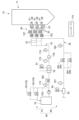
図1は、本実施形態の固体燃料と液化燃料を主燃料とするボイラを備える燃焼システムを表す概略構成図である。液化燃料は、大気圧下の常温において気相となる燃料である。本明細書でいう常温は35℃である。液化燃料は、例えば石油(軽質油や液化石油ガス)、液化天然ガス、ジメチルエーテル、および液体アンモニアなどである。以下の説明では特段の説明がない限り、液化燃料は液体アンモニアを指すものとする。
1. Overall configuration of combustion system 1
1 is a schematic diagram showing a combustion system including a boiler using solid fuel and liquefied fuel as main fuels according to the present embodiment. The liquefied fuel is a fuel that is in a gas phase at room temperature under atmospheric pressure. The room temperature in this specification is 35° C. The liquefied fuel is, for example, petroleum (light oil or liquefied petroleum gas), liquefied natural gas, dimethyl ether, and liquid ammonia. In the following description, unless otherwise specified, the liquefied fuel refers to liquid ammonia.
本実施形態の燃焼システム1が備えるボイラ10は、固体燃料を粉砕した微粉燃料と、液化燃料とをバーナにより燃焼させ、この燃焼により発生した熱を給水や蒸気と熱交換して過熱蒸気を生成することが可能なボイラである。固体燃料としては、バイオマス燃料や石炭などが使用される。
The
ボイラ10は、火炉11と燃焼装置20、50と燃焼ガス通路12を有している。火炉11は、四角筒の中空形状をなして鉛直方向に沿って設置されている。火炉11の内壁面を構成する火炉壁101は、複数の伝熱管と、伝熱管同士を接続するフィンとで構成され、微粉燃料の燃焼により発生した熱を、伝熱管の内部を流通する水や蒸気と熱交換して回収すると共に、火炉壁101の温度上昇を抑制している。
The
燃焼装置20、50は、火炉11の下部領域に設置されている。本実施形態では、燃焼装置20は、微粉燃料を火炉11の内部に噴射するように構成される。また、燃焼装置50は、液化燃料をアトマイズ流体(噴霧媒体)により微粒化して火炉11の内部に噴射するように構成される。本実施形態のアトマイズ流体はアトマイズ蒸気である。
The
燃焼装置20は、火炉壁101に装着された複数のバーナ21を有し、燃焼装置50は、複数のバーナ51を有している。各々のバーナ21の先端部には、微粉燃料を火炉11内に噴射するように構成された噴射ノズル(図示外)が設けられる。また、各々のバーナ51の先端部には、液化燃料をアトマイズ流体により微粒化して火炉11内に噴射するように構成された2流体噴射ノズル59(図4参照)が設けられる。
バーナ21、51は、火炉11の周方向に沿って均等間隔で配設されたもの(例えば、四角形の火炉11の各コーナ部に設置された4個)を1セットとして、鉛直方向に沿って複数段配置されている。図1の例では、1セットのバーナ21が2段、1セットのバーナ51が4段配置される。なお、図1では、図示の都合上、1セットのバーナのうちの2個のみを記載し、各セットに符合21、51を付している。火炉の形状やバーナの段数、一つの段におけるバーナの数、バーナの配置などは、この実施形態に限定されるものではない。
The
The
燃焼装置20のバーナ21は、それぞれ、複数の微粉燃料供給管22A、22B(以下、一括して「微粉燃料供給管22」と記載する場合がある。)を介して、複数のミル(粉砕機)31A、31B(以下、一括して「ミル31」と記載する場合がある。)に連結されている。ミル31は、例えば、内部に粉砕テーブル(図示省略)が駆動回転可能に支持されていて、粉砕テーブルの上方に複数の粉砕ローラ(図示省略)が粉砕テーブルの回転に連動回転可能に支持されて構成されている竪型ローラミルである。粉砕ローラと粉砕テーブルが協働して粉砕された固体燃料は、ミル31に供給される一次空気(搬送用ガス、酸化性ガス)により、ミル31が備える分級機(図示省略)に搬送される。分級機では、バーナ21での燃焼に適した粒径以下の微粉燃料と、該粒径より大きな粗粉燃料とに分級される。微粉燃料は、分級機を通過して、一次空気と共に微粉燃料供給管22を介してバーナ21に供給される。分級機を通過しなかった粗粉燃料は、ミル31の内部で、自重により粉砕テーブル上に落下し、再粉砕される。
The
燃焼装置50のバーナ51は、供給ユニット90に連結されている。供給ユニット90は、燃焼装置50にアトマイズ流体を供給するように構成された2流体噴射ノズル用のアトマイズ流体供給ユニット60(以下、単に「アトマイズ流体供給ユニット60」と記載する場合がある。)と、燃焼装置50に液化燃料を供給するように構成された2流体噴射ノズル用の液化燃料供給ユニット70(以下、単に「液化燃料供給ユニット70」と記載する場合がある。)とを含む。ボイラ10における燃焼負荷に応じて定まるバーナ51での液化燃料の要求噴射流量を、コントローラ110が取得する。コントローラ110が要求噴射流量に応じた制御指令を供給ユニット90に送ることで、アトマイズ流体供給ユニット60と液化燃料供給ユニット70はそれぞれ、アトマイズ流体と液化燃料の供給量を調整することができる。供給ユニット90の構成の詳細は後述する。
なお、液化燃料の要求噴射流量は、各バーナ51の2流体噴射ノズル59(図4参照)1個当たりの液化燃料の要求噴射流量である。
The
The required injection flow rate of the liquefied fuel is the required injection flow rate of the liquefied fuel per one two-fluid injection nozzle 59 (see FIG. 4) of each
バーナ21、51の装着位置における火炉11の炉外側には、エアレジスタ23が設けられており、このエアレジスタ23には風道(空気ダクト)24の一端部が連結されている。風道24の他端部には、押込通風機(FDF:Forced Draft Fan)32が連結されている。押込通風機32から供給された空気は、風道24に設置された空気予熱器42で加熱され(詳細は後述する)、エアレジスタ23を介してバーナ21に二次空気(燃焼用空気、酸化性ガス)として供給され、火炉11の内部に投入される。
An
燃焼ガス通路12は、火炉11の鉛直方向上部に連結されている。燃焼ガス通路12には、燃焼ガスの熱を回収するための熱交換器として、過熱器102A、102B、102C(以下、一括して「過熱器102」と記載する場合がある。)、再熱器103A、103B(以下、一括して「再熱器103」と記載する場合がある。)、節炭器104が設けられており、火炉11で発生した燃焼ガスと各熱交換器の内部を流通する給水や蒸気との間で熱交換が行われる。なお、各熱交換器の配置や形状は、図1に記載した形態に限定されない。
The
燃焼ガス通路12の下流側には、熱交換器で熱回収された燃焼ガスが排出される煙道13が連結されている。煙道13には、風道24との間に空気予熱器(エアヒータ)42が設けられており、風道24を流れる空気と、煙道13を流れる燃焼ガスとの間で熱交換を行い、ミル31に供給する一次空気やバーナ21に供給する二次空気を加熱することで、水や蒸気との熱交換後の燃焼ガスから、さらに熱回収を行う。
The
また、煙道13には、空気予熱器42よりも上流側の位置に、脱硝装置43が設けられていてもよい。脱硝装置43は、アンモニア、尿素水等の窒素酸化物を還元する作用を有する還元剤を、煙道13内を流通する燃焼ガスに供給し、還元剤が供給された燃焼ガス中の窒素酸化物(NOx)と還元剤との反応を、脱硝装置43内に設置された脱硝触媒の触媒作用により促進させることで、燃焼ガス中の窒素酸化物を除去、低減するものである。
煙道13の空気予熱器42より下流側には、ガスダクト41が連結されている。ガスダクト41には、燃焼ガス中の灰などを除去する電気集じん機などの集じん装置44や硫黄酸化物を除去する脱硫装置46などの環境装置、また、それらの環境装置に排ガスを導くための誘引通風機(IDF:Induced Draft Fan)45が設けられている。ガスダクト41の下流端部は、煙突47に連結されており、環境装置で処理された燃焼ガスが、排ガスとして系外に排出される。
Further, a
A
ボイラ10において、複数のミル31が駆動すると、粉砕、分級された微粉燃料が、一次空気と共に微粉燃料供給管22を介してバーナ21に供給される。また、アトマイズ流体供給ユニット60と液化燃料供給ユニット70からそれぞれアトマイズ流体と液化燃料がバーナ51に供給される。さらに、空気予熱器42で加熱された二次空気が、風道24からエアレジスタ23を介してバーナ21、51に供給される。
バーナ21は、微粉燃料と一次空気とが混合した微粉燃料混合気を火炉11に吹き込むと共に、二次空気を火炉11に吹き込む。火炉11に吹き込まれた微粉燃料混合気が着火し、二次空気と反応することで火炎を形成する。バーナ51は、アトマイズ流体によって微粒化された液化燃料と共に二次空気を火炉11に吹き込む。火炉11に吹き込まれた液化燃料は、気化して燃料ガスになり、二次空気と反応して燃焼する。
微粉燃料と燃料ガスの燃焼により生じる高温の燃焼ガスは、火炉11内を上昇し、燃焼ガス通路12に流入する。
なお、液化燃料が火炉11に吹き込まれるタイミングは、微粉燃料の燃焼によって火炉11内の温度が一定温度まで上昇した後であってもよい。例えば、ボイラ10の起動時に微粉燃料の専焼が行われたのち、液化燃料が火炉11に吹き込まれ、液化燃料が気化した燃料ガスと微粉燃料との混焼が行われてもよい。さらにその後、微粉燃料の吹き込みを停止し、液化燃料の専焼が行われてもよい。
また、本実施形態では、酸化性ガス(一次空気、二次空気)として空気を用いるが、空気よりも酸素割合が多いものや逆に少ないものであってもよく、供給される燃料量に対する酸素量の比率を適正な範囲に調整することで、火炉11において安定した燃焼が実現される。
In the
The
High-temperature combustion gas generated by the combustion of the pulverized fuel and the fuel gas rises within the
The timing for injecting the liquefied fuel into the
In addition, in this embodiment, air is used as the oxidizing gas (primary air, secondary air), but the oxidizing gas may have a higher or lower oxygen content than air, and stable combustion in the
燃焼ガス通路12に流入した燃焼ガスは、燃焼ガス通路12の内部に配置された過熱器102、再熱器103、節炭器104で水や蒸気と熱交換した後、煙道13に排出され、脱硝装置43で窒素酸化物が除去され、空気予熱器42で一次空気及び二次空気と熱交換した後、さらにガスダクト41に排出され、集じん装置44で灰などが除去され、脱硫装置46で硫黄酸化物が除去された後、煙突47から系外に排出される。なお、燃焼ガス通路12における各熱交換器及び煙道13からガスダクト41における各装置の配置は、燃焼ガス流れに対して、必ずしも上述の記載順に配置されなくともよい。
The combustion gas that flows into the
上述した実施形態では、本開示のボイラを、燃料に固体燃料と液化燃料を使用するボイラとして説明した。ボイラに使用される固体燃料としては、石炭、バイオマス燃料、石油コークス(PC:Petroleum Coke)燃料、石油残渣などが使用される。
なお、液化燃料と組み合わせるボイラの燃料としては、固体燃料に限らず、重油、軽油、重質油などの石油類や工場廃液などの液体燃料も使用することができる。また、天然ガスや各種石油ガス、製鉄プロセスなどで発生する副生ガスなどの気体燃料も使用することができる。
さらに、これらの各種燃料を組み合わせて使用する混焼ボイラにも適用することができる。
In the above-described embodiment, the boiler of the present disclosure has been described as a boiler that uses solid fuel and liquefied fuel as fuel. The solid fuel used in the boiler may be coal, biomass fuel, petroleum coke (PC) fuel, petroleum residue, or the like.
The fuel for the boiler combined with liquefied fuel is not limited to solid fuel, but can also be liquid fuel such as petroleum such as heavy oil, light oil, and heavy oil, and industrial waste liquid. In addition, gaseous fuels such as natural gas, various petroleum gases, and by-product gases generated in the steelmaking process can also be used.
Furthermore, the present invention can be applied to a multi-fuel boiler that uses a combination of these various fuels.
<2.液化燃料供給ユニット70の構成>
図2を参照し、上述した供給ユニット90の構成要素である液化燃料供給ユニット70の構成を例示する。図2は、本開示の一実施形態に係る供給ユニットの概念的な構成図である。なお、図2では、図面を見やすくする都合、燃焼装置20(図1参照)の図示を省略している。
2. Configuration of the liquefied
With reference to Fig. 2, a configuration of a liquefied
液化燃料供給ユニット70は、液化燃料を貯留する貯留部79と、貯留部79に貯留される液化燃料をバーナ51の2流体噴射ノズル59に供給するため液化燃料供給ライン75と、液化燃料供給ライン75に設けられた加熱器76と、液化燃料供給ライン75に設けられた液化燃料調整部78とを備える。
The liquefied
貯留部79は、液化燃料の一例である液体アンモニアを貯留する。液化燃料供給ライン75の下流端は、複数のバーナ51がそれぞれ備える2流体噴射ノズル59の構成要素である液化燃料供給路57に接続される。液化燃料供給ライン75の上流側部分には、供給される液化燃料の一部を貯留部79に戻すための戻し路752が設けられる。加熱器76は、液化燃料を気化させない程度の一定温度まで加熱するように構成される。加熱器76の熱源は、一例として、燃焼システム1において生成される蒸気の一部である補助蒸気である。加熱器76による加熱により、火炉11に吹き込まれる液化燃料は気化し易く、火炉11における失火を抑制することができる。なお、加熱器76によって加熱された液化燃料の温度を計測するための温度計175の計測結果に基づき、補助蒸気の流路に設けられた調整弁81が調整され、加熱器76における液化燃料の加熱量が調整される。本例ではこの調整がコントローラ110によって実行される。
The
液化燃料調整部78は、上述した液化燃料の要求噴射流量に応じて液化燃料の供給圧力と流量を調整するように構成される。
本実施形態の液化燃料調整部78は、戻し路752において並列に設けられた容量の異なる複数の制御弁781と液化燃料供給ライン75に設けられた制御弁782である。制御弁781は例えば圧力調整弁であり、制御弁782は例えば流量調整弁である。本例では、液化燃料供給ライン75の戻し路752との分岐点の下流側に設けられた圧力計173及び液体燃料供給路57との分岐点の上流側に設けられた流量計176のそれぞれの計測結果に基づき、複数の制御弁781と制御弁782はコントローラ110によって制御される。より具体的な一例として、コントローラ110は、要求噴射流量に相当する流量の液化燃料がバーナ51に供給されるよう、圧力計173と流量計176のそれぞれの計測結果に基づき複数の制御弁781と制御弁782をそれぞれ制御する。
The liquefied
The liquefied
なお、他の実施形態では、液化燃料供給ユニット70は、貯留部79を備えなくてもよい。例えば、液化燃料供給ライン75は、液化燃料を貯留する大型タンクローリなどの船舶や液化燃料を製造する設備とパイプラインにより接続されてもよい。
In other embodiments, the liquefied
<3.アトマイズ流体供給ユニット60の構成>
図2を参照し、上述した供給ユニット90の構成要素であるアトマイズ流体供給ユニット60の構成を例示する。アトマイズ流体供給ユニット60は、バーナ51の2流体噴射ノズル59にアトマイズ流体を供給するためのアトマイズ流体供給ライン55と、アトマイズ流体供給ライン55に設けられた減温器53と、アトマイズ流体供給ライン55に設けられたアトマイズ流体調整部58とを備える。アトマイズ流体供給ライン55は、複数のバーナ51がそれぞれ備える2流体噴射ノズル59の構成要素であるアトマイズ流体供給路52に接続される。
3. Configuration of the atomized
2, the configuration of an atomized
減温器53は、アトマイズ流体よりも温度の低い冷却媒体を用いてアトマイズ流体を一定温度まで減温させるように構成される。本実施形態では、アトマイズ流体は蒸気であり、減温器53で、スプレイ水を混合してアトマイズ流体を減温させる。例えば、スプレイ水管に設けられたスプレイ水調整弁54が、減温器53よりも下流側に設けられた温度計161の計測結果に基づきコントローラ110により制御される。
The
アトマイズ流体調整部58は、上述した液化燃料の要求噴射流量に応じて、アトマイズ流体の供給圧力を調整するように構成される。
本実施形態のアトマイズ流体調整部58は、減温器53よりも下流側において並列に設けられた容量の異なる複数の制御弁581である。本例では、アトマイズ流体調整部58よりも下流側に設けられた圧力計182の計測結果に基づき、複数の制御弁581は制御される。より詳細には一例として、コントローラ110は、液化燃料の要求噴射流量に対応する圧力のアトマイズ流体がバーナ51に供給されるよう、圧力計182の計測結果に基づき複数の制御弁581をそれぞれ制御する。
The atomized
The atomized
<4.2流体噴射ノズル59における液化燃料の流量制御>
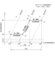
図3を参照し、2流体噴射ノズル59における液化燃料の流量制御の詳細を例示する。図3は、本開示の一実施形態に係る2流体噴射ノズルから噴射される液化燃料の流量と液化燃料の供給圧力との関係を概念的に示すグラフである。
図3のグラフの横軸は、2流体噴射ノズル59から噴射される液化燃料流量(Q)を示す。
同グラフの縦軸は液化燃料の供給圧力(Pf)を示す。縦軸にあるPf0とPf1は、それぞれ、バーナ51において安定した燃焼を実現するための液化燃料のバーナ下限圧力とバーナ上限圧力である。また、PfVは、バーナ51へ液化燃料を安定して供給するための供給下限圧力であり、加熱器76によって加熱された液化燃料の温度における液化燃料の蒸気圧に応じた値である。
<4. Flow rate control of liquefied fuel in two-
3, a detailed example of flow rate control of the liquefied fuel in the two-
The horizontal axis of the graph in FIG. 3 represents the flow rate (Q) of the liquefied fuel injected from the two-
The vertical axis of the graph indicates the supply pressure (Pf) of the liquefied fuel. Pf 0 and Pf 1 on the vertical axis are the burner lower limit pressure and the burner upper limit pressure, respectively, of the liquefied fuel for realizing stable combustion in the
同グラフにおいて概念的に描かれるグラフ線Aは、アトマイズ流体の供給圧力(Pa)がPa1であるときの、流量と液化燃料の供給圧力との関係を示す。また、グラフ線B、Cは、アトマイズ流体の供給圧力(Pa)がそれぞれPa2、Pa3であるときの、流量と液化燃料の供給圧力との関係を示す。なお、アトマイズ流体の供給圧力(Pa)について、以下の式(1)が成立している。
Pa1>Pa2>Pa3 ・・・(1)
なお、必ずしもアトマイズ供給圧力(Pa)が3つの圧力である必要はなく更に多くの圧力や少ない圧力で制御することも可能である。また、Paの最小圧力がゼロすなわちアトマイズ流体が供給されない場合でも良い。
Graph line A, which is conceptually drawn in the graph, shows the relationship between the flow rate and the supply pressure of the liquefied fuel when the supply pressure (Pa) of the atomized fluid is Pa1. Graph lines B and C show the relationship between the flow rate and the supply pressure of the liquefied fuel when the supply pressure (Pa) of the atomized fluid is Pa2 and Pa3, respectively. Note that the following formula (1) is established for the supply pressure (Pa) of the atomized fluid.
Pa1>Pa2>Pa3...(1)
The atomizing supply pressure (Pa) does not necessarily have to be three pressures, and it is possible to control with more or less pressures. Also, it is acceptable for the minimum pressure of Pa to be zero, that is, for no atomizing fluid to be supplied.
本実施形態では、液体燃料の供給圧力とアトマイズ流体の供給圧力を変更することで、2流体噴射ノズル59から噴射される液化燃料の流量が調整される。以下ではその詳細を、グラフの点J1で示される状態から点J4で示される状態まで液化燃料の流量が下がる場合を例に説明する。
In this embodiment, the flow rate of the liquefied fuel injected from the two-
はじめに、液化燃料調整部78が液化燃料の供給圧力(Pf)をPf1に維持しつつ、アトマイズ流体調整部58がアトマイズ流体の供給圧力(Pa)をPa3からPa2まで上げる。これにより、液化燃料の流量Qは、Q4からQ3まで低下する(点J2)。このとき、液化燃料の供給圧力が維持されるので、液化燃料の流動は安定化しやすい。
その後、アトマイズ流体調整部58がアトマイズ流体の供給圧力をPa2に維持しつつ、液化燃料調整部78が液化燃料の供給圧力をPf1からPfdまで下げる(Pfdは後述のPfVよりも大きい)。これにより、液化燃料の流量が低下する(点J3)。
さらに、液化燃料調整部78が液化燃料の供給圧力をPfdに維持しつつ、アトマイズ流体調整部58がアトマイズ流体の供給圧力をPa2からPa1まで上げる。これにより、液化燃料の流量が低下する(点J4)。
First, the liquefied
Thereafter, while the atomized
Furthermore, the liquefied
液化燃料の供給圧力(Pf)とアトマイズ流体の供給圧力(Pa)の双方を変更することで液化燃料の流量を制御する利点は、以下の通りである。
液化燃料の噴射量は液化燃料の供給圧力と相関する。従って、例えば2流体噴射ノズル59における液化燃料の要求噴射流量が低下することに応じて液化燃料の流量を下げるべく、アトマイズ流体の供給圧力(Pa)を例えばPa3に維持して、液化燃料の供給圧力(Pf)のみを下げた場合、液化燃料の供給圧力(Pf)は、供給下限圧力であるPfVを下回り易い。結果として、液化燃料の供給圧力が液化燃料の蒸気圧以下となり、例えば液化燃料供給ライン75または2流体噴射ノズル59などにおいてベーパロックが生じ、液化燃料の流動が不安定になるおそれがある。これは、比較的沸点の高い油ではなく、比較的沸点の低い液体アンモニアなどが液化燃料として用いられる場合に特に生じやすい。
この点、上記構成によれば、液化燃料の要求噴射流量に応じてアトマイズ流体調整部58によりアトマイズ流体の供給圧力(Pa)を調整することで、液化燃料の供給圧力を液化燃料の蒸気圧以上に維持する場合であっても、液化燃料の噴射流量を広範囲で調整できる。これにより、液化燃料の供給圧力が液化燃料の蒸気圧以下まで低下することに起因した上述のベーパロックの発生が抑制される。従って、液化燃料の供給経路や2流体噴射ノズル59における液化燃料の流動を安定化させることができる。
The advantages of controlling the flow rate of the liquefied fuel by changing both the supply pressure (Pf) of the liquefied fuel and the supply pressure (Pa) of the atomizing fluid are as follows.
The injection amount of the liquefied fuel correlates with the supply pressure of the liquefied fuel. Therefore, for example, in order to reduce the flow rate of the liquefied fuel in response to a decrease in the required injection flow rate of the liquefied fuel in the two-
In this regard, according to the above configuration, the atomized
また、以下に示す利点も得られる。
すなわち、アトマイズ流体の供給圧力(Pa)が例えばPa2に維持されて、液化燃料の供給圧力(Pf)が調整される場合、Pfが最大可変域(PfV≦Pf≦Pf1)で調整されたとしても、流量の変更量はΔQ0で示される範囲にとどまり、液化燃料の流量調整幅は狭い。この点、液化燃料の供給圧力(Pf)とアトマイズ流体の供給圧力(Pa)の双方を変更することで流量を調整すると、Pfが最大可変域よりも狭い範囲(Pfd≦Pf≦Pf1)で調整されても、流量の変更量はΔQ1で示される範囲で調整でき、液化燃料の流量調整幅を広げることができる。
In addition, the following advantages are obtained:
That is, when the supply pressure (Pa) of the atomized fluid is maintained at, for example, Pa2 and the supply pressure (Pf) of the liquefied fuel is adjusted, even if Pf is adjusted within the maximum variable range ( PfV ≦Pf≦ Pf1 ), the amount of change in the flow rate remains within the range indicated by ΔQ0 , and the flow rate adjustment range of the liquefied fuel is narrow. In this regard, when the flow rate is adjusted by changing both the supply pressure (Pf) of the liquefied fuel and the supply pressure (Pa) of the atomized fluid, even if Pf is adjusted within a range narrower than the maximum variable range ( Pfd ≦Pf≦ Pf1 ), the amount of change in the flow rate can be adjusted within the range indicated by ΔQ1 , and the flow rate adjustment range of the liquefied fuel can be expanded.
なお、点J1で示される状態から点J4で示される状態までの流量の変更手順は、上記の説明に限定されない。他の実施形態では、アトマイズ流体の供給圧力をPa3からPa1まで上げてから、液化燃料の供給圧力をPf1からPfdまで下げてもよい。この場合であっても、上記の利点を享受することができる。
また、液化燃料の要求噴射流量に応じて、流量は、点J1で示される状態から点J2で示される状態に変化した後に、点J1で示す状態に戻ってもよい。同様に、流量は、点J2で示される状態と点J3で示される状態との間、または、点J3で示される状態と点J4で示される状態との間で変更されてもよい。
以下の説明では、点J1から点J2までの流量に対応する液化燃料の要求噴射流量の範囲と、点J3から点J4までの流量に対応する液化燃料の要求噴射流量の範囲を、いずれも「第1範囲」と記載する場合がある。また、点J2から点J3までの流量に対応する液化燃料の要求噴射流量の範囲を「第2範囲」と記載する場合がある。
The procedure for changing the flow rate from the state indicated by point J1 to the state indicated by point J4 is not limited to the above description. In another embodiment, the supply pressure of the atomized fluid may be increased from Pa3 to Pa1, and then the supply pressure of the liquefied fuel may be decreased from Pf1 to Pfd . Even in this case, the above-mentioned advantages can be obtained.
Also, depending on the required injection flow rate of the liquefied fuel, the flow rate may change from the state indicated by point J1 to the state indicated by point J2, and then return to the state indicated by point J1. Similarly, the flow rate may be changed between the state indicated by point J2 and the state indicated by point J3, or between the state indicated by point J3 and the state indicated by point J4.
In the following description, the range of the required injection flow rate of the liquefied fuel corresponding to the flow rate from point J1 to point J2 and the range of the required injection flow rate of the liquefied fuel corresponding to the flow rate from point J3 to point J4 may both be referred to as a "first range." Furthermore, the range of the required injection flow rate of the liquefied fuel corresponding to the flow rate from point J2 to point J3 may be referred to as a "second range."
本実施形態では、液化燃料の要求噴射流量の第1範囲において、コントローラ110は、アトマイズ流体調整部58によりアトマイズ流体の供給圧力を液化燃料の要求噴射流量に応じて変化させる。また、液化燃料の要求噴射流量の第2範囲において、コントローラ110は、液化燃料調整部78により液化燃料の供給圧力を要求噴射流量に応じて変化させる。
上記構成によれば、コントローラ110がアトマイズ流体調整部58と液化燃料調整部78を同時に制御することが抑制されるので、コントローラ110による液化燃料の噴射流量の制御が簡易になる。また、アトマイズ流体調整部58と液化燃料調整部78による制御が相互に干渉することが抑制されるので、制御される液化燃料の流量も安定化する。
In this embodiment, in a first range of the required injection flow rate of the liquefied fuel, the
According to the above configuration, the
また、本実施形態では、コントローラ110は、第1範囲において、液化燃料調整部78により、液化燃料の供給圧力が一定となるよう(図3の例では供給圧力がPf1またはPfdになるよう)、液化燃料の供給流量(供給量)を制御する。つまり、液化燃料の供給圧力が一定になるよう、複数の制御弁781(図2参照)の開度がコントローラ110によって制御される。
上記構成によれば、アトマイズ流体の供給圧力が調整されるときに液化燃料の供給圧力が一定に維持されるので、液化燃料とアトマイズ流体とが混合されるときの液化燃料の圧力変動を安定化させることができる。よって、2流体噴射ノズル59は液化燃料を安定的に噴射することができる。
In this embodiment, the
According to the above-mentioned configuration, since the supply pressure of the liquefied fuel is maintained constant when the supply pressure of the atomized fluid is adjusted, it is possible to stabilize the pressure fluctuation of the liquefied fuel when the liquefied fuel and the atomized fluid are mixed. Therefore, the two-
また、本実施形態では、第1範囲は、要求噴射流量の低流量範囲と、低流量範囲よりも高流量な高流量範囲とを含む。低流量範囲は、点J3と点J4の間における流量に対応する要求噴射流量の範囲であり、高流量範囲は、点J1と点J2の間における流量に対応する要求噴射流量の範囲である。また、第2範囲は、低流量範囲と高流量範囲の間となる中流量範囲である。
上記構成によれば、液化燃料の要求噴射流量の可変域のうち、要求される頻度が比較的高い中流量範囲においては、コントローラ110は、液化燃料の供給圧力を変化させる。従って、要求される頻度が比較的高い中流量範囲において、液化燃料の流量をより高精度に調整することができる。
In this embodiment, the first range includes a low flow rate range of the required injection flow rate and a high flow rate range that is higher than the low flow rate range. The low flow rate range is the range of the required injection flow rate corresponding to the flow rate between points J3 and J4, and the high flow rate range is the range of the required injection flow rate corresponding to the flow rate between points J1 and J2. The second range is a medium flow rate range between the low flow rate range and the high flow rate range.
According to the above configuration, in the medium flow rate range where the required injection flow rate of the liquefied fuel is required relatively frequently among the variable range of the required injection flow rate of the liquefied fuel, the
また、本実施形態では、上述したように、アトマイズ流体調整部58(図2参照)は、並列に設けられた容量の異なる複数の制御弁581を備える。そして、コントローラ110は、複数の制御弁581のそれぞれの開度を制御することでアトマイズ流体の供給圧力を制御し、液化燃料の流量を制御する。
上記構成によれば、容量の比較的大きな制御弁581でアトマイズ流体の供給圧力の大まかな調整がなされ、容量の比較的小さな制御弁581で供給圧力の細かな調整がなされる。よって、要求噴射流量の調整範囲が広範囲になる場合であっても、該調整範囲に対応するアトマイズ流体の供給圧力の範囲内において、アトマイズ流体の供給圧力を高精度に制御することができる。
In this embodiment, as described above, the atomized fluid adjusting unit 58 (see FIG. 2) includes a plurality of
According to the above configuration, the supply pressure of the atomized fluid is roughly adjusted by the
また、本実施形態では、上述したように、液化燃料調整部78は、並列に設けられた容量の異なる複数の制御弁781を備える(図2参照)。そして、コントローラ110は、複数の制御弁781のそれぞれの開度を制御することで液化燃料の供給圧力を制御し、液化燃料の流量を制御する。
上記構成によれば、容量の比較的大きな制御弁781で液化燃料の供給圧力の大まかな調整がなされ、容量の比較的小さな制御弁781で供給圧力の細かな調整がなされる。よって、広範な液化燃料の流量範囲に対応する液化燃料の供給圧力範囲内において、液化燃料の供給圧力を高精度に制御することができる。そして、本実施形態では、液化燃料の供給圧力の高精度な制御を、要求頻度の高い第2範囲において行うことができる。
In this embodiment, as described above, the liquefied
According to the above configuration, the supply pressure of the liquefied fuel is roughly adjusted by the
また、本実施形態では、液化燃料供給ユニット70の構成要素である貯留部79は、液体アンモニアを貯留する液体アンモニア貯留部として機能する。つまり、2流体噴射ノズル59に供給される液化燃料として液体アンモニアが採用される。これにより、カーボンニュートラルに寄与し、環境負荷を低減することができる。
In addition, in this embodiment, the
<5.バーナ51の概要の例示>
図4を参照し、バーナ51の構成の概要を例示する。図4は本開示の一実施形態に係るバーナの概略的な構成図である。バーナ51の構成要素である2流体噴射ノズル59は、少なくとも1つ以上の第1噴射孔591と、少なくとも1つ以上の第2噴射孔592とを含む。第1噴射孔591と第2噴射孔592はそれぞれ、液化燃料とアトマイズ流体の混合流体を噴射するように構成される。言い換えると、第1噴射孔591と第2噴射孔592のそれぞれから、アトマイズ流体によって微粒化された液化燃料が噴射される。
本実施形態では、液化燃料とアトマイズ流体が供給される供給路が、第1噴射孔591と第2噴射孔592とで独立している。以下ではこの供給路の詳細を説明する。
5. Example of Outline of
Referring to Fig. 4, an outline of the configuration of the
In this embodiment, the supply passages through which the liquefied fuel and the atomizing fluid are supplied are independent for the
液化燃料の供給路は、一例として以下の通りである。
2流体噴射ノズル59は、上述した液化燃料供給ライン75に接続される液化燃料供給路57を含む。この液化燃料供給路57は、第1噴射孔591及び第2噴射孔592にそれぞれ液化燃料を導くための第1液化燃料供給路571及び第2液化燃料供給路572を有する。また、液化燃料供給路57には、第1液化燃料供給路571と第2液化燃料供給路572とのそれぞれにおける液化燃料の供給を独立して変更するように構成された複数の液化燃料弁157が設けられる。そして、複数の液化燃料弁157は、第1液化燃料供給路571に設けられた第1液化燃料開閉弁157Aと、第2液化燃料供給路572に設けられた第2液化燃料開閉弁157Bとを有する。第1液化燃料開閉弁157Aと第2液化燃料開閉弁157Bが、コントローラ110によって制御されることで、第1噴射孔591と第2噴射孔592のそれぞれに向けた液化燃料の供給が独立して行われる。
An example of the supply path for the liquefied fuel is as follows.
The two-
アトマイズ流体の供給路は、一例として以下の通りである。
2流体噴射ノズル59は、上述したアトマイズ流体供給ライン55に接続されるアトマイズ流体供給路52を含む。このアトマイズ流体供給路52は、第1噴射孔591及び第2噴射孔592にそれぞれアトマイズ流体を導くための第1アトマイズ流体供給路521及び第2アトマイズ流体供給路522を有する。また、アトマイズ流体供給路52には、第1アトマイズ流体供給路521と第2アトマイズ流体供給路522とのそれぞれにおけるアトマイズ流体の供給を独立して変更するように構成された複数のアトマイズ流体弁152が設けられる。そして、複数のアトマイズ流体弁152は、第1アトマイズ流体供給路521に設けられた第1アトマイズ流体弁152Aと、第2アトマイズ流体供給路522に設けられた第2アトマイズ流体弁152Bとを有する。第1アトマイズ流体弁152Aと第2アトマイズ流体弁152Bが、コントローラ110によって制御されることで、第1噴射孔591と第2噴射孔592のそれぞれに向けたアトマイズ流体の供給が独立して行われる。
An example of the supply path of the atomizing fluid is as follows.
The two-
本実施形態では、アトマイズ流体供給路52と液化燃料供給路57は、2流体噴射ノズル59における軸線を基準とした周方向において、互いにずれた位置に設けられる。より詳細には、第1アトマイズ流体供給路521、第2アトマイズ流体供給路522、第1液化燃料供給路571、及び第2液化燃料供給路572は、周方向において互いにずれた位置に設けられる(図6の右側図を参照)。2流体噴射ノズル59の軸線からこれら4つの供給路までの径方向距離は、同じであってもよいし、異なってもよい。
In this embodiment, the atomized
上記構成によれば、アトマイズ流体供給路52と液化燃料供給路57とが周方向に離隔することで、アトマイズ流体供給路52を流れるアトマイズ流体から液化燃料供給路57を流れる液化燃料への入熱が抑制される。より具体的には、第1液化燃料供給路571と第2液化燃料供給路572とのそれぞれにおける液化燃料が、第1アトマイズ流体供給路521と第2アトマイズ流体供給路522とのそれぞれにおけるアトマイズ流体から周方向に離隔することで、アトマイズ流体から液化燃料への入熱が抑制される。よって、液化燃料が気化することによる、2流体噴射ノズル59の内部におけるベーパロックを抑制できる。
According to the above configuration, the atomized
また、本実施形態では、図4で示されるアトマイズ流体供給路52と液化燃料供給路57との間が熱的に絶縁されている。より具体的には、第1液化燃料供給路571または第2液化燃料供給路572のいずれかと、第1アトマイズ流体供給路521または第2アトマイズ流体供給路522のいずれかとの間が熱的に絶縁されている。熱的な絶縁は、アトマイズ流体から液化燃料への熱伝達が、2流体噴射ノズル59の軸線方向における少なくとも一部において阻止されることである。本実施形態では、これら4つの供給路が互いに熱的に絶縁されており、より詳細には、断熱材88が設けられることで熱的に絶縁されている(図6参照)。2流体噴射ノズル59の軸線方向において、断熱材88の長さは、2流体噴射ノズル59の全長の半分以上であることが好ましく、4分の3以上であるとさらに好ましい。
なお、他の実施形態では、熱的な絶縁は、アトマイズ流体供給路52と液化燃料供給路57と間に冷却空気の流路が配置されることで実現されてもよい。
In this embodiment, the atomized
In other embodiments, thermal insulation may be achieved by arranging a cooling air flow path between the atomizing
上記構成によれば、アトマイズ流体供給路52を流れるアトマイズ流体と液化燃料供給路57を流れる液化燃料が熱的に絶縁される。より具体的には、第1液化燃料供給路571または第2液化燃料供給路572の少なくとも一方における液化燃料と、第1アトマイズ流体供給路521または第2アトマイズ流体供給路522の少なくとも一方におけるアトマイズ流体とが熱的に絶縁される。これにより、アトマイズ流体から液化燃料への入熱がさらに抑制されるので、2流体噴射ノズル59におけるベーパロックをさらに抑制できる。
According to the above configuration, the atomized fluid flowing through the atomized
また、本実施形態では、上述した貯留部79が液化燃料供給ライン75を介して液化燃料供給路57に接続される。本実施形態の貯留部79は、液化燃料としての液体アンモニアを貯留する液体アンモニア貯留部である。図3の例では、第1液化燃料供給路571と第2液化燃料供給路572が単一の貯留部79に接続されているが、これら2つの供給路に対応して2つの貯留部79が設けられてもよい。
上記構成によれば、カーボンニュートラルに寄与し、環境負荷を低減することができる。
In this embodiment, the above-mentioned
The above configuration contributes to carbon neutrality and reduces the environmental impact.
上述のように、液化燃料弁157とアトマイズ流体弁152は、コントローラ110によって制御される。より詳細には、第1液化燃料開閉弁157A、第2液化燃料開閉弁157B、第1アトマイズ流体弁152A、及び第2アトマイズ流体弁152Bは、それぞれコントローラ110によって独立して制御される。これにより、液体アンモニアとアトマイズ流体の供給あり/なしの制御が、第1噴射孔591と第2噴射孔592のそれぞれにおいて独立して制御される。
As described above, the liquefied
上記構成によれば、第1噴射孔591と第2噴射孔592のそれぞれにおいて、液化燃料の流量可変域が拡大する。つまり、第1液化燃料供給路571と第2液化燃料供給路572のそれぞれの液化燃料の流量可変域を過剰に広く設定しなくても、第1液化燃料供給路571と第2液化燃料供給路572のそれぞれにおける液化燃料の供給あり/なしの選択により、燃焼システム1の全体としての広範囲な液化燃料の流量可変域を実現できる。よって、液化燃料供給路57や2流体噴射ノズル59の内部でのベーパロックのリスクを抑制しつつ、燃焼システム1での液化燃料の広い流量可変域を実現できる。
According to the above configuration, the flow rate variable range of the liquefied fuel is expanded in each of the
本実施形態では、液化燃料の要求噴射流量が比較的少ない場合には、第1噴射孔591と第2噴射孔592のうち第1噴射孔591のみが作動するよう、液化燃料弁157とアトマイズ流体弁152は制御される。そして、液化燃料の要求噴射流量が、第1噴射孔591における液化燃料の噴射量の上限を上回るとき、第1噴射孔591に加えて第2噴射孔592が作動するよう、液化燃料弁157とアトマイズ流体弁152は制御される。
より具体的には、要求噴射流量が液化燃料の流量可変域の第1設定範囲に含まれるとき、コントローラ110は、第1液化燃料開閉弁157Aと第2液化燃料開閉弁157Bのうち第1液化燃料開閉弁157Aのみを開く。このとき、第1アトマイズ流体弁152Aと第2アトマイズ流体弁152Bのうち第1アトマイズ流体弁152Aのみが開いてもよい。
そして、液化燃料の要求噴射流量が、第1設定範囲よりも高流量な第2設定範囲に含まれる場合、コントローラ110は、第1液化燃料開閉弁157Aに加えて、第2液化燃料開閉弁157Bをさらに開く。このとき、第1アトマイズ流体弁152Aに加えて第2アトマイズ流体弁152Bが開いてもよい。
In this embodiment, when the required injection flow rate of liquefied fuel is relatively small, the liquefied
More specifically, when the required injection flow rate is included in a first set range of the flow rate variable range of the liquefied fuel, the
When the required injection flow rate of the liquefied fuel is included in a second setting range that is higher than the first setting range, the
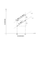
図5は、上記の制御が行われた場合の、液化燃料の供給圧力と噴射流量との関係を概念的に示すグラフである。グラフの横軸は、液化燃料の供給圧力(Pf)を示し、Pfdと、Pf1は図3を用いて既述した通りである。同グラフの縦軸は、第1噴射孔591と第2噴射孔592から噴射される液化燃料の合計流量を示す。なお、同グラフでは、アトマイズ流体の供給圧力はPa2である。
グラフで示される直線L1は、第1液化燃料開閉弁157Aのみを開いたときの流量特性を示す。従って、グラフで示す寸法R1が第1設定範囲に相当する。そして、第1設定範囲は、図3を用いて既述した第2範囲に相当する。
グラフで示される直線L2は、第1液化燃料開閉弁157Aに加えて、第2液化燃料開閉弁157Bをさらに開いたときの流量特性を示す。従って、寸法R2が第2設定範囲に相当する。
5 is a graph conceptually showing the relationship between the supply pressure of the liquefied fuel and the injection flow rate when the above control is performed. The horizontal axis of the graph indicates the supply pressure (Pf) of the liquefied fuel, where Pfd and Pf1 are as described above with reference to FIG. 3. The vertical axis of the graph indicates the total flow rate of the liquefied fuel injected from the
A straight line L1 shown in the graph indicates the flow rate characteristics when only the first liquefied fuel on-off
A straight line L2 shown in the graph indicates the flow rate characteristics when the second liquefied fuel on-off
上記構成によれば、燃焼システム1における液化燃料の要求噴射流量が第1設定範囲内にあるときは、第1液化燃料供給路571と第2液化燃料供給路572とのうち第1液化燃料供給路571のみが使用される。また、液化燃料の要求噴射流量が第1設定範囲よりも高流量な第2設定範囲内にあるときに、第1液化燃料供給路571に加えて第2液化燃料供給路572も併せて使用される。よって、第1液化燃料供給路571と第2液化燃料供給路572のそれぞれにおける液化燃料の供給あり/なしの選択により、燃焼システム1の全体としての広範囲な液化燃料の流量可変域を実現できる。つまり、液化燃料供給路57や2流体噴射ノズル59の内部でのベーパロックのリスクを抑制しつつ、燃焼システム1での液化燃料の広い流量可変域を実現できる。
According to the above configuration, when the required injection flow rate of the liquefied fuel in the combustion system 1 is within the first set range, only the first liquefied
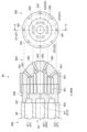
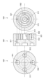
<6.2流体噴射ノズル59の構成の詳細>
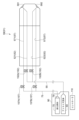
図6、図7を参照し、2流体噴射ノズル59の構成の詳細を例示する。図6は、本開示の一実施形態に係る2流体噴射ノズルの概略的な説明図である。図7は、本開示の一実施形態に係るバックプレートの概略的な説明図である。
本開示の一実施形態に係る2流体噴射ノズル59は、液化燃料供給路57及びアトマイズ流体供給路52が設けられるバーナガン560と、第1噴射孔591及び第2噴射孔592が設けられるスプレイプレート590と、バーナガン560及びスプレイプレート590を連結するバックプレート550とを備える。
<6.2 Details of the Configuration of the
6 and 7, the detailed configuration of the two-
A two-
本実施形態のバーナガン560では、液化燃料供給路57とアトマイズ流体供給路52との間は断熱材88によって熱的に遮断されている。
本実施形態のスプレイプレート590では、複数の第1噴射孔591が、2流体噴射ノズル59の軸線を基準とした周方向に沿って配置される。各々の第1噴射孔591の上流側には、供給される液化燃料とアトマイズ流体とが混合される混合室601が形成される。また、2流体噴射ノズル59の軸方向視において複数の第1噴射孔591よりも内側には、複数の第2噴射孔592が周方向に沿って配置されている。各々の第2噴射孔592の上流側には、供給される液化燃料とアトマイズ流体とが混合される混合室602が形成される。
In the
In the
本実施形態のバックプレート550は、第1液化燃料供給路571、第1アトマイズ流体供給路521、第2液化燃料供給路572、及び第2アトマイズ流体供給路522と、第1噴射孔591及び第2噴射孔592との流路(混合室601、602)を接続する。
具体的には、バックプレート550は、第1液化燃料供給路571に連結される第1液化燃料連結路501と、第1アトマイズ流体供給路521に連結される第1アトマイズ流体連結路511と、第2液化燃料供給路572に連結される第2液化燃料連結路502と、第2アトマイズ流体供給路522に連結される第2アトマイズ流体連結路512とを備える。本実施形態では、これらの連結路は、バックプレート550の先端側(噴射側)と基端側とで非対称な形状を呈する。具体的には、これらの連結路の基端側は、2流体噴射ノズル59の軸線方向に対して平行または傾斜する円柱状の流路を画定する一方で、先端側の各連結路は、軸線方向視において円環状の流路を画定する。
The
Specifically, the
上記構成によれば、バックプレート550の先端側と後端側での非対称になっている複雑な流路であっても、円滑に漏洩なく、液化燃料とアトマイズ流体とを流すことができる。
The above configuration allows the liquefied fuel and atomized fluid to flow smoothly and without leakage, even in a complex flow path that is asymmetric between the front and rear ends of the
<7.供給方法の例示>
図8を参照し、液化燃料とアトマイズ流体を2流体噴射ノズル59に供給する方法を説明する。図8は、本開示の一実施形態に係る液化燃料とアトマイズ流体を供給する方法を示すフローチャートである。以下の説明では、「ステップ」を「S」と略記する場合がある。本例の供給方法は、一例としてコントローラ110によって実行される。
<7. Examples of supply methods>
A method of supplying liquefied fuel and atomized fluid to the two-
はじめに、コントローラ110は、ボイラ10の燃焼負荷を取得する(S11)。これにより、コントローラ110は、燃焼負荷に応じた液化燃料の要求噴射流量を取得する。
次いで、コントローラ110は、取得した要求噴射流量に応じた液化燃料の供給圧力とアトマイズ流体の供給圧力を取得し、これらの供給圧力が実現されるよう、液化燃料調整部78とアトマイズ流体調整部58を制御する。本ステップの制御は、図3を用いて既述した通りである。例えば、液化燃料の要求噴射流量が第1範囲に含まれる場合には、コントローラ110はアトマイズ流体調整部58を制御してアトマイズ流体の供給圧力を変化させる。
本実施形態ではこのとき、液化燃料の供給圧力が一定になるよう、コントローラ110は液化燃料調整部78を制御する。上記構成によれば、液化燃料の流動は安定化する。
First, the
Next, the
At this time, in this embodiment, the
次いで、コントローラ110は、S11の実行に伴い取得された液化燃料の要求噴射流量が第1設定範囲に含まれるか否かを判定する(S15)。要求噴射流量が第1設定範囲に含まれる場合には(S15:YES)、コントローラ110は、第1噴射孔591と第2噴射孔592のうち第1噴射孔591のみが作動するよう、第1液化燃料開閉弁157Aと第1アトマイズ流体弁152Aを開く(S17)。一方、要求噴射流量が第2設定範囲に含まれる場合(S15:NO)、第1噴射孔591に加えて第2噴射孔592が作動するよう、コントローラ110は、第1液化燃料開閉弁157Aと第1アトマイズ流体弁152Aに加えて、第2液化燃料開閉弁157Bと第2アトマイズ流体弁152Bを開く(S19)。
つまり、要求噴射流量に応じてS17またはS19のいずれかが実行されることで、第1液化燃料供給路571と第2液化燃料供給路572のそれぞれにおける液化燃料の供給が独立して変更される。
S17またはS19の実行後、コントローラ110は処理を終了する。
Next, the
In other words, by executing either S17 or S19 depending on the required injection flow rate, the supply of liquefied fuel in each of the first liquefied
After executing S17 or S19, the
<8.まとめ>
上述した幾つかの実施形態に記載の内容は、例えば以下のように把握されるものである。
8. Summary
The contents described in the above-mentioned embodiments can be understood, for example, as follows.
1)本開示の少なくとも一実施形態に係る2流体噴射ノズル(59)は、
液化燃料とアトマイズ流体とを噴射するための少なくとも1つ以上の第1噴射孔(591)及び少なくとも1つ以上の第2噴射孔(592)を含む2流体噴射ノズル(59)であって、
前記液化燃料と前記アトマイズ流体とをそれぞれ前記第1噴射孔(591)に導くための第1液化燃料供給路(571)及び第1アトマイズ流体供給路(521)と、
前記液化燃料と前記アトマイズ流体とをそれぞれ前記第2噴射孔(592)に導くための第2液化燃料供給路(572)及び第2アトマイズ流体供給路(522)と、をさらに含み、
前記第1液化燃料供給路(571)または前記第2液化燃料供給路(572)のいずれかと、前記第1アトマイズ流体供給路(521)または前記第2アトマイズ流体供給路(522)のいずれかとの間が熱的に絶縁される。
1) A two-fluid injection nozzle (59) according to at least one embodiment of the present disclosure comprises:
A two-fluid injection nozzle (59) including at least one or more first injection holes (591) and at least one or more second injection holes (592) for injecting a liquefied fuel and an atomizing fluid,
a first liquefied fuel supply passage (571) and a first atomized fluid supply passage (521) for respectively guiding the liquefied fuel and the atomized fluid to the first injection hole (591);
a second liquefied fuel supply passage (572) and a second atomized fluid supply passage (522) for respectively guiding the liquefied fuel and the atomized fluid to the second injection hole (592),
Either the first liquefied fuel supply passage (571) or the second liquefied fuel supply passage (572) is thermally insulated from either the first atomized fluid supply passage (521) or the second atomized fluid supply passage (522).
上記1)の構成によれば、第1液化燃料供給路(571)または第2液化燃料供給路(572)の少なくとも一方を流れる液化燃料と、第1アトマイズ流体供給路(521)または第2アトマイズ流体供給路(522)の少なくとも一方を流れるアトマイズ流体とが熱的に絶縁される。これにより、アトマイズ流体から液体アンモニアへの入熱が抑制されるので、2流体噴射ノズル(59)内部におけるベーパロックを抑制できる。よって、2流体噴射ノズル(59)は、液化燃料の流動を安定化させることができる。 According to the configuration of 1) above, the liquefied fuel flowing through at least one of the first liquefied fuel supply passage (571) or the second liquefied fuel supply passage (572) is thermally insulated from the atomized fluid flowing through at least one of the first atomized fluid supply passage (521) or the second atomized fluid supply passage (522). This suppresses heat input from the atomized fluid to the liquid ammonia, thereby suppressing vapor lock inside the two-fluid injection nozzle (59). Therefore, the two-fluid injection nozzle (59) can stabilize the flow of the liquefied fuel.
2)幾つかの実施形態では、上記1)に記載の2流体噴射ノズル(59)であって、
前記第1液化燃料供給路(571)、前記第1アトマイズ流体供給路(521)、前記第2液化燃料供給路(572)、及び前記第2アトマイズ流体供給路(522)は、前記2流体噴射ノズルの軸線を基準とした周方向において互いにずれた位置に設けられる。
2) In some embodiments, the two-fluid injection nozzle (59) described in 1) above,
The first liquefied fuel supply passage (571), the first atomized fluid supply passage (521), the second liquefied fuel supply passage (572), and the second atomized fluid supply passage (522) are arranged at positions offset from each other in the circumferential direction based on the axis of the two-fluid injection nozzle.
上記2)の構成によれば、第1液化燃料供給路(571)と第2液化燃料供給路(572)とのそれぞれにおける液化燃料が、第1アトマイズ流体供給路(521)と第2アトマイズ流体供給路(522)とのそれぞれにおけるアトマイズ流体から周方向に離隔することで、アトマイズ流体から液化燃料への入熱を抑制できる。よって、2流体噴射ノズル(59)内部におけるベーパロックをさらに抑制できる。 According to the configuration of 2) above, the liquefied fuel in each of the first liquefied fuel supply passage (571) and the second liquefied fuel supply passage (572) is circumferentially separated from the atomized fluid in each of the first atomized fluid supply passage (521) and the second atomized fluid supply passage (522), thereby suppressing heat input from the atomized fluid to the liquefied fuel. Therefore, vapor lock inside the two-fluid injection nozzle (59) can be further suppressed.
3)幾つかの実施形態では、上記1)または2)のいずれかに記載の2流体噴射ノズル(59)であって、
前記第1液化燃料供給路(571)、前記第1アトマイズ流体供給路(521)、前記第2液化燃料供給路(572)、及び前記第2アトマイズ流体供給路(522)と、前記第1噴射孔(591)及び前記第2噴射孔(592)との流路を接続するバックプレート(550)を備える。
3) In some embodiments, the two-fluid injection nozzle (59) described in either 1) or 2) above,
The fuel injection nozzle is provided with a back plate (550) that connects the first liquefied fuel supply passage (571), the first atomized fluid supply passage (521), the second liquefied fuel supply passage (572), and the second atomized fluid supply passage (522) to the first injection hole (591) and the second injection hole (592).
上記3)の構成によれば、バックプレート(550)の噴射孔側である先端側と基端側とで非対称になっている複雑な流路が形成される場合であっても、液化燃料とアトマイズ流体とを円滑に漏洩なく流すことができる。 According to the configuration 3) above, even when a complex flow path is formed that is asymmetric between the tip side, which is the injection hole side of the back plate (550), and the base end side, the liquefied fuel and the atomized fluid can flow smoothly without leakage.
4)本開示の少なくとも一実施形態に係る燃焼システム(1)は、
上記1)から3)のいずれかの2流体噴射ノズル(59)と、
前記第1液化燃料供給路(571)と前記第2液化燃料供給路(572)とのそれぞれにおける前記液化燃料の供給を独立して変更するための複数の液化燃料弁(157)と、
前記第1アトマイズ流体供給路(521)と前記第2アトマイズ流体供給路(522)とのそれぞれにおける前記アトマイズ流体の供給を独立して変更するための複数のアトマイズ流体弁(152)とを備える。
4) At least one embodiment of the combustion system (1) according to the present disclosure includes:
A two-fluid jet nozzle (59) according to any one of 1) to 3) above;
a plurality of liquefied fuel valves (157) for independently varying the supply of liquefied fuel in each of the first liquefied fuel supply passage (571) and the second liquefied fuel supply passage (572);
and a plurality of atomizing fluid valves (152) for independently varying the supply of the atomizing fluid in each of the first atomizing fluid supply passage (521) and the second atomizing fluid supply passage (522).
上記4)の構成によれば、第1噴射孔(591)と第2噴射孔(592)のそれぞれに対応する液化燃料の供給路である第1液化燃料供給路(571)と第2液化燃料供給路(572)の液化燃料の流量可変域を過剰に広く設定しなくても、第1液化燃料供給路(571)と第2液化燃料供給路(572)の各々における液化燃料の供給あり/なしの選択により、燃焼システム(1)全体としての広範囲な液化燃料の流量可変域を実現できる。よって、液化燃料供給路(57)または2流体噴射ノズル(59)内部などでのベーパロックのリスクを抑制しつつ、燃焼システム(1)での液化燃料の広い流量可変域を実現できる。 According to the configuration of 4) above, even if the variable flow rate range of the liquefied fuel in the first liquefied fuel supply passage (571) and the second liquefied fuel supply passage (572), which are the supply passages of the liquefied fuel corresponding to the first injection hole (591) and the second injection hole (592), respectively, is not set excessively wide, a wide variable flow rate range of the liquefied fuel can be realized in the entire combustion system (1) by selecting whether or not the liquefied fuel is supplied in each of the first liquefied fuel supply passage (571) and the second liquefied fuel supply passage (572). Therefore, a wide variable flow rate range of the liquefied fuel in the combustion system (1) can be realized while suppressing the risk of vapor lock inside the liquefied fuel supply passage (57) or the two-fluid injection nozzle (59), etc.
5)幾つかの実施形態では、上記4)に記載の燃焼システム(1)であって、
前記複数の液化燃料弁(157)を制御するためのコントローラ(110)を備え、
前記複数の液化燃料弁(157)は、
前記第1液化燃料供給路(571)に設けられた第1液化燃料開閉弁(157A)と、
前記第2液化燃料供給路(572)に設けられた第2液化燃料開閉弁(157B)と、を含み、
前記コントローラ(110)は、
前記2流体噴射ノズル1個当たりの前記液化燃料の要求噴射流量が前記液化燃料の流量可変域の第1設定範囲に含まれる場合、前記第1液化燃料開閉弁(157A)と前記第2液化燃料開閉弁(157B)のうち前記第1液化燃料開閉弁(157A)のみを開き、
前記要求噴射流量が前記流量可変域の前記第1設定範囲よりも高流量な第2設定範囲に含まれる場合、前記第1液化燃料開閉弁(157A)と前記第2液化燃料開閉弁(157B)とを開くように構成される。
5) In some embodiments, the combustion system (1) according to 4) above,
a controller (110) for controlling the plurality of liquefied fuel valves (157);
The plurality of liquefied fuel valves (157)
a first liquefied fuel on-off valve (157A) provided in the first liquefied fuel supply passage (571);
a second liquefied fuel on-off valve (157B) provided in the second liquefied fuel supply passage (572),
The controller (110)
When the required injection flow rate of the liquefied fuel per one of the two-fluid injection nozzles is within a first setting range of a flow rate variable range of the liquefied fuel, only the first liquefied fuel on-off valve (157A) of the first liquefied fuel on-off valve (157A) and the second liquefied fuel on-off valve (157B) is opened,
When the required injection flow rate is included in a second setting range that is higher than the first setting range of the flow rate variable region, the first liquefied fuel on-off valve (157A) and the second liquefied fuel on-off valve (157B) are configured to be opened.
上記5)の構成によれば、燃焼システム(1)における液化燃料の要求噴射流量が第1設定範囲内にあるときは、第1液化燃料供給路(571)と第2液化燃料供給路(572)とのうち第1液化燃料供給路(571)のみが使用される。また、上記液化燃料の要求噴射流量が第1設定範囲よりも高流量な第2設定範囲内にあるときに、第1液化燃料供給路(571)に加えて第2液化燃料供給路(572)も併せて使用される。よって、第1液化燃料開閉弁(157A)と第2液化燃料開閉弁(157B)が同時に使用されるタイミングが限定されるので、コントローラ(110)による第1液化燃料開閉弁(157A)と第2液化燃料開閉弁(157B)との制御を簡易にすることができる。 According to the configuration of 5) above, when the required injection flow rate of the liquefied fuel in the combustion system (1) is within the first set range, only the first liquefied fuel supply path (571) is used out of the first liquefied fuel supply path (571) and the second liquefied fuel supply path (572). Also, when the required injection flow rate of the liquefied fuel is within a second set range that is higher than the first set range, the second liquefied fuel supply path (572) is used in addition to the first liquefied fuel supply path (571). Therefore, since the timing when the first liquefied fuel on-off valve (157A) and the second liquefied fuel on-off valve (157B) are used simultaneously is limited, the control of the first liquefied fuel on-off valve (157A) and the second liquefied fuel on-off valve (157B) by the controller (110) can be simplified.
6)幾つかの実施形態では、上記4)または5)に記載の燃焼システム(1)であって、
前記第1液化燃料供給路(571)と前記第2液化燃料供給路(572)のそれぞれに接続され、前記液化燃料としての液体アンモニアを貯留するする少なくとも1つの液体アンモニア貯留部(貯留部79)をさらに含む。
6) In some embodiments, the combustion system (1) according to 4) or 5) above,
The fuel cell further includes at least one liquid ammonia storage section (storage section 79) that is connected to each of the first liquefied fuel supply passage (571) and the second liquefied fuel supply passage (572) and stores liquid ammonia as the liquefied fuel.
上記6)の構成によれば、カーボンニュートラルへ寄与し、環境負荷を低減できる。 The configuration in 6) above contributes to carbon neutrality and reduces the environmental impact.
7)本開示の少なくとも一実施形態に係る液化燃料の供給量の制御方法は、
上記4)から6)のいずれかの燃焼システム(1)を用いた液化燃料の供給量の制御方法であって、
前記第1液化燃料供給路(571)と、前記第2液化燃料供給路(572)とのそれぞれにおける、前記液化燃料の供給を、独立して変更するステップ(S17、S19)を備える。
7) A method for controlling a supply amount of liquefied fuel according to at least one embodiment of the present disclosure,
A method for controlling a supply amount of liquefied fuel using any one of the combustion systems (1) of 4) to 6), comprising:
The method includes steps (S17, S19) of independently changing the supply of the liquefied fuel in each of the first liquefied fuel supply passage (571) and the second liquefied fuel supply passage (572).
上記7)の構成によれば、上記4)と同様の理由により、液化燃料供給路(57)または2流体噴射ノズル(59)などでのベーパロックのリスクを抑制しつつ、燃焼システム(1)での液化燃料の広い流量可変域を実現できる。 According to the configuration of 7) above, for the same reason as 4) above, it is possible to realize a wide variable flow rate range of the liquefied fuel in the combustion system (1) while suppressing the risk of vapor lock in the liquefied fuel supply passage (57) or the two-fluid injection nozzle (59), etc.
1 :燃焼システム
52 :アトマイズ流体供給路
57 :液化燃料供給路
59 :2流体噴射ノズル
79 :貯留部
110 :コントローラ
152 :アトマイズ流体弁
157 :液化燃料弁
157A :第1液化燃料開閉弁
157B :第2液化燃料開閉弁
521 :第1アトマイズ流体供給路
522 :第2アトマイズ流体供給路
550 :バックプレート
571 :第1液化燃料供給路
572 :第2液化燃料供給路
591 :第1噴射孔
592 :第2噴射孔
1: Combustion system 52: Atomized fluid supply passage 57: Liquefied fuel supply passage 59: Two-fluid injection nozzle 79: Storage section 110: Controller 152: Atomized fluid valve 157: Liquefied
Claims (9)
前記燃焼ガス通路の下流に設けられた脱硝装置と、
を備え、
前記噴射ノズルは、前記液体アンモニアを液状のまま微粒化して前記火炉の内部に噴射できるように構成されている
ことを特徴とする燃焼システム。 A boiler having a furnace including a furnace wall, an injection nozzle for injecting liquid ammonia as a fuel into the inside of the furnace, and a combustion gas passage;
a denitration device provided downstream of the combustion gas passage;
Equipped with
The combustion system is characterized in that the injection nozzle is configured to atomize the liquid ammonia while keeping it in a liquid state and inject it into the inside of the furnace.
前記燃焼ガス通路の下流に設けられ、燃焼ガス中の窒素酸化物を除去または低減する脱硝装置と、
を備え、
前記複数のバーナは前記火炉壁に装着されており、
前記燃焼装置は、前記液体アンモニアを液状のまま微粒化して前記火炉の内部に噴射できるように構成されている
ことを特徴とする燃焼システム。 A boiler having a furnace including a furnace wall, a combustion device having a plurality of burners each having an injection nozzle at its tip for injecting liquid ammonia as fuel into the inside of the furnace, and a combustion gas passage having a heat exchanger for recovering heat of the combustion gas;
a denitration device provided downstream of the combustion gas passage for removing or reducing nitrogen oxides in the combustion gas;
Equipped with
The burners are attached to the furnace wall,
The combustion system is characterized in that the combustion device is configured to atomize the liquid ammonia while it is in a liquid state and inject the liquid ammonia into the inside of the furnace.
前記燃焼ガス通路の下流に設けられた脱硝装置と、
を備え、
前記噴射ノズルは、前記液体アンモニアを水蒸気と混合させて前記火炉の内部に噴射できるように構成されている
ことを特徴とする燃焼システム。 A boiler having a furnace including a furnace wall, an injection nozzle for injecting liquid ammonia as a fuel into the inside of the furnace, and a combustion gas passage;
a denitration device provided downstream of the combustion gas passage;
Equipped with
The combustion system is characterized in that the injection nozzle is configured to mix the liquid ammonia with water vapor and inject the mixture into the inside of the furnace.
前記燃焼ガス通路の下流に設けられ、燃焼ガス中の窒素酸化物を除去または低減する脱硝装置と、
を備え、
前記複数のバーナは前記火炉壁に装着されており、
前記燃焼装置は、前記液体アンモニアを水蒸気と混合させて前記火炉の内部に噴射できるように構成されている
ことを特徴とする燃焼システム。 A boiler having a furnace including a furnace wall, a combustion device having a plurality of burners each having an injection nozzle at its tip for injecting liquid ammonia as fuel into the inside of the furnace, and a combustion gas passage having a heat exchanger for recovering heat of the combustion gas;
a denitration device provided downstream of the combustion gas passage for removing or reducing nitrogen oxides in the combustion gas;
Equipped with
The burners are attached to the furnace wall,
2. A combustion system comprising: a combustion device configured to mix the liquid ammonia with steam and inject the mixture into the furnace;
石油コークス燃料、その他の石油残渣、重油、軽油、重質油、その他の石油類、工場廃液、石炭、バイオマス燃料、天然ガス、石油ガス、製鉄プロセスで発生する副生ガス、の何れか1つ又はこれらの各種燃料を組み合わせた燃料を前記火炉の内部に噴射する第一噴射ノズルと、
燃料としての液体アンモニアを前記火炉の内部に噴射する第二噴射ノズルと、
燃焼ガス通路と、
を有するボイラと、
前記燃焼ガス通路の下流に設けられた脱硝装置と、
を備え、
前記第二噴射ノズルは、前記液体アンモニアを液状のまま微粒化して前記火炉の内部に噴射できるように構成されている
ことを特徴とする燃焼システム。 a furnace including a furnace wall;
a first injection nozzle for injecting fuel into the furnace, the fuel being any one of petroleum coke fuel, other petroleum residues, heavy oil, light oil, heavy oil, other petroleum products, industrial wastewater, coal, biomass fuel, natural gas, petroleum gas, by-product gas generated in a steelmaking process, or a combination of these various fuels;
A second injection nozzle that injects liquid ammonia as a fuel into the inside of the furnace;
A combustion gas passage;
A boiler having
a denitration device provided downstream of the combustion gas passage;
Equipped with
The combustion system is characterized in that the second injection nozzle is configured to atomize the liquid ammonia while keeping it in a liquid state and inject it into the inside of the furnace.
石油コークス燃料、その他の石油残渣、重油、軽油、重質油、その他の石油類、工場廃液、石炭、バイオマス燃料、天然ガス、石油ガス、製鉄プロセスで発生する副生ガス、の何れか1つ又はこれらの各種燃料を組み合わせた燃料を前記火炉の内部に噴射する第一噴射ノズルを先端部に設けた複数の第一バーナを有する第一燃焼装置と、
燃料としての液体アンモニアを前記火炉の内部に噴射する第二噴射ノズルを先端部に設けた複数の第二バーナを有する第二燃焼装置と、
燃焼ガスの熱を回収するための熱交換器を設けた燃焼ガス通路と、
を有するボイラと、
前記燃焼ガス通路の下流に設けられ、燃焼ガス中の窒素酸化物を除去または低減する脱硝装置と、
を備え、
前記複数の第一バーナおよび前記複数の第二バーナは前記火炉壁に装着されており、
前記第二燃焼装置は、前記液体アンモニアを液状のまま微粒化して前記火炉の内部に噴射できるように構成されている
ことを特徴とする燃焼システム。 a furnace including a furnace wall;
a first combustion device having a plurality of first burners each having a first injection nozzle at its tip for injecting fuel into the furnace, the fuel being any one of petroleum coke fuel, other petroleum residues, heavy oil, light oil, heavy oil, other petroleum products, industrial wastewater, coal, biomass fuel, natural gas, petroleum gas, by-product gas generated in a steelmaking process, or a combination of these various fuels;
A second combustion device having a plurality of second burners each having a second injection nozzle at its tip for injecting liquid ammonia as fuel into the inside of the furnace;
a combustion gas passage provided with a heat exchanger for recovering heat from the combustion gas;
A boiler having
a denitration device provided downstream of the combustion gas passage for removing or reducing nitrogen oxides in the combustion gas;
Equipped with
The first burners and the second burners are mounted on the furnace wall,
The combustion system is characterized in that the second combustion device is configured to atomize the liquid ammonia while it is in a liquid state and inject it into the inside of the furnace.
ことを特徴とする請求項1~8の何れか1つに記載の燃焼システム。 A desulfurization device is provided downstream of the denitration device and removes sulfur oxides from the combustion gas.
A combustion system according to any one of claims 1 to 8.
Priority Applications (1)
| Application Number | Priority Date | Filing Date | Title |
|---|---|---|---|
| JP2025025582A JP7686898B1 (en) | 2021-09-08 | 2025-02-20 | Combustion System |
Applications Claiming Priority (2)
| Application Number | Priority Date | Filing Date | Title |
|---|---|---|---|
| JP2021146425A JP2023039309A (en) | 2021-09-08 | 2021-09-08 | Two-fluid injection nozzle, combustion system, and method for controlling supply amount of liquefied fuel |
| JP2025025582A JP7686898B1 (en) | 2021-09-08 | 2025-02-20 | Combustion System |
Related Parent Applications (1)
| Application Number | Title | Priority Date | Filing Date |
|---|---|---|---|
| JP2021146425A Division JP2023039309A (en) | 2021-09-08 | 2021-09-08 | Two-fluid injection nozzle, combustion system, and method for controlling supply amount of liquefied fuel |
Publications (2)
| Publication Number | Publication Date |
|---|---|
| JP7686898B1 true JP7686898B1 (en) | 2025-06-02 |
| JP2025087731A JP2025087731A (en) | 2025-06-10 |
Family
ID=85506603
Family Applications (3)
| Application Number | Title | Priority Date | Filing Date |
|---|---|---|---|
| JP2021146425A Pending JP2023039309A (en) | 2021-09-08 | 2021-09-08 | Two-fluid injection nozzle, combustion system, and method for controlling supply amount of liquefied fuel |
| JP2024210876A Active JP7661601B2 (en) | 2021-09-08 | 2024-12-04 | Boiler |
| JP2025025582A Active JP7686898B1 (en) | 2021-09-08 | 2025-02-20 | Combustion System |
Family Applications Before (2)
| Application Number | Title | Priority Date | Filing Date |
|---|---|---|---|
| JP2021146425A Pending JP2023039309A (en) | 2021-09-08 | 2021-09-08 | Two-fluid injection nozzle, combustion system, and method for controlling supply amount of liquefied fuel |
| JP2024210876A Active JP7661601B2 (en) | 2021-09-08 | 2024-12-04 | Boiler |
Country Status (3)
| Country | Link |
|---|---|
| JP (3) | JP2023039309A (en) |
| TW (1) | TW202319684A (en) |
| WO (1) | WO2023037866A1 (en) |
Families Citing this family (2)
| Publication number | Priority date | Publication date | Assignee | Title |
|---|---|---|---|---|
| JP2023039309A (en) | 2021-09-08 | 2023-03-20 | 三菱重工業株式会社 | Two-fluid injection nozzle, combustion system, and method for controlling supply amount of liquefied fuel |
| CN118009312A (en) * | 2024-02-02 | 2024-05-10 | 东方电气集团东方锅炉股份有限公司 | A high-power pure ammonia low-nitrogen burner |
Citations (5)
| Publication number | Priority date | Publication date | Assignee | Title |
|---|---|---|---|---|
| CN106621750A (en) | 2016-11-30 | 2017-05-10 | 东方电气集团东方锅炉股份有限公司 | A spray gun system used for SCR-SNCR combined denitration for W flame boilers |
| JP3220107U (en) | 2018-08-14 | 2019-02-14 | 赫普科技発展(北京)有限公司 | Electrolytic hydrogen production and ammonia synthesis system in thermal power plant |
| CN209470213U (en) | 2018-08-29 | 2019-10-08 | 赫普科技发展(北京)有限公司 | A kind of ammonia mixture swirl flow combustion system |
| JP2023039309A (en) | 2021-09-08 | 2023-03-20 | 三菱重工業株式会社 | Two-fluid injection nozzle, combustion system, and method for controlling supply amount of liquefied fuel |
| JP7369158B2 (en) | 2021-03-31 | 2023-10-25 | 三菱重工業株式会社 | Ammonia fuel boiler and ammonia supply system |
Family Cites Families (18)
| Publication number | Priority date | Publication date | Assignee | Title |
|---|---|---|---|---|
| JPS5613454Y2 (en) * | 1971-08-10 | 1981-03-28 | ||
| JPS49142834U (en) * | 1973-04-04 | 1974-12-10 | ||
| JPS5083826A (en) * | 1973-11-28 | 1975-07-07 | ||
| FR2288940A1 (en) * | 1974-10-24 | 1976-05-21 | Pillard Chauffage | IMPROVEMENTS TO LIQUID FUEL BURNERS SPRAYED BY THE RELIEF OF AN AUXILIARY FLUID AND METHOD OF USING THE latter |
| JPS51149167A (en) * | 1975-06-18 | 1976-12-21 | Babcock Hitachi Kk | A method of feeding ammonia |
| JPS5461336A (en) * | 1977-10-21 | 1979-05-17 | Mitsubishi Heavy Ind Ltd | Combustion process of low temperature liquefied gas fuel |
| JPS59170609A (en) * | 1983-03-17 | 1984-09-26 | Tamiko Yamamoto | Method for improving combustion of boiler and the like by means of adapter with heater |
| JPS6086720U (en) * | 1983-11-22 | 1985-06-14 | 石川島播磨重工業株式会社 | heavy oil burner |
| JPH01101024U (en) * | 1987-12-21 | 1989-07-06 | ||
| JPH07253203A (en) * | 1994-03-16 | 1995-10-03 | Ishikawajima Harima Heavy Ind Co Ltd | Burner |
| JPH09329326A (en) * | 1996-06-06 | 1997-12-22 | Nippon Oil Co Ltd | Control method of burner for liquid fuel combustion |
| US20050074383A1 (en) * | 2003-10-01 | 2005-04-07 | Wojichowski David Lee | Process and injection apparatus for reducing the concentration of NOX pollutants in an effluent |
| JP2008045836A (en) * | 2006-08-18 | 2008-02-28 | Babcock Hitachi Kk | Burner tip, burner device and boiler apparatus including it |
| JP4892379B2 (en) * | 2007-03-23 | 2012-03-07 | 出光エンジニアリング株式会社 | Fuel combustion device |
| US8899969B2 (en) | 2011-06-09 | 2014-12-02 | Gas Technology Institute | Method and system for low-NOx dual-fuel combustion of liquid and/or gaseous fuels |
| JP2018028391A (en) | 2014-12-22 | 2018-02-22 | 三菱日立パワーシステムズ株式会社 | Burner tip, combustion burner, and boiler |
| JP7039782B2 (en) | 2018-03-30 | 2022-03-23 | 三菱重工業株式会社 | Thermal power plant, co-firing boiler and boiler modification method |
| JP7227827B2 (en) * | 2019-03-29 | 2023-02-22 | 株式会社Ihi原動機 | Combustion device |
-
2021
- 2021-09-08 JP JP2021146425A patent/JP2023039309A/en active Pending
-
2022
- 2022-08-23 TW TW111131615A patent/TW202319684A/en unknown
- 2022-08-23 WO PCT/JP2022/031663 patent/WO2023037866A1/en not_active Ceased
-
2024
- 2024-12-04 JP JP2024210876A patent/JP7661601B2/en active Active
-
2025
- 2025-02-20 JP JP2025025582A patent/JP7686898B1/en active Active
Patent Citations (5)
| Publication number | Priority date | Publication date | Assignee | Title |
|---|---|---|---|---|
| CN106621750A (en) | 2016-11-30 | 2017-05-10 | 东方电气集团东方锅炉股份有限公司 | A spray gun system used for SCR-SNCR combined denitration for W flame boilers |
| JP3220107U (en) | 2018-08-14 | 2019-02-14 | 赫普科技発展(北京)有限公司 | Electrolytic hydrogen production and ammonia synthesis system in thermal power plant |
| CN209470213U (en) | 2018-08-29 | 2019-10-08 | 赫普科技发展(北京)有限公司 | A kind of ammonia mixture swirl flow combustion system |
| JP7369158B2 (en) | 2021-03-31 | 2023-10-25 | 三菱重工業株式会社 | Ammonia fuel boiler and ammonia supply system |
| JP2023039309A (en) | 2021-09-08 | 2023-03-20 | 三菱重工業株式会社 | Two-fluid injection nozzle, combustion system, and method for controlling supply amount of liquefied fuel |
Also Published As
| Publication number | Publication date |
|---|---|
| TW202319684A (en) | 2023-05-16 |
| JP2023039309A (en) | 2023-03-20 |
| JP2025026508A (en) | 2025-02-21 |
| JP2025087731A (en) | 2025-06-10 |
| WO2023037866A1 (en) | 2023-03-16 |
| JP7661601B2 (en) | 2025-04-14 |
Similar Documents
| Publication | Publication Date | Title |
|---|---|---|
| JP7686898B1 (en) | Combustion System | |
| US20120315586A1 (en) | METHOD AND SYSTEM FOR LOW-NOx DUAL-FUEL COMBUSTION OF LIQUID AND/OR GASEOUS FUELS | |
| CN102165254A (en) | Oxy/fuel combustion system with minimized flue gas recirculation | |
| TW202303042A (en) | Ammonia fuel boiler and ammonia supply system | |
| TW202340650A (en) | Ammonia combustion burner, boiler, and boiler operation method | |
| JP7781570B2 (en) | Atomizing fluid supply unit for two-fluid injection nozzle, supply unit, combustion system, and supply method | |
| WO2023120404A1 (en) | Ammonia fuel boiler system | |
| JP2008107031A (en) | Tubular flame burner and radiant tube heating device | |
| JP7680916B2 (en) | Combustion equipment and boilers | |
| CN118189175A (en) | Burner with a burner body | |
| WO2019015486A1 (en) | Alcohol-based fuel vaporization and combustion device | |
| WO2023120395A1 (en) | Ammonia combustion burner and boiler | |
| JP2020003185A (en) | Gas combustion device and vacuum water warmer | |
| JP2012063132A (en) | Tubular flame burner and radiation tube heating apparatus | |
| JP6715026B2 (en) | boiler | |
| JP2023094928A (en) | Ammonia fuel boiler system | |
| JP2025005036A (en) | Premixing device and boiler, and method for modifying a boiler | |
| KR102903407B1 (en) | Ammonia fuel boiler and ammonia supply system | |
| JP2025002654A (en) | Burner, boiler and combustion method | |
| JP2025006583A (en) | Boiler, boiler modification method, and boiler operation method | |
| JPH1151312A (en) | Low NOx combustion device for liquid fuel | |
| JP2025088205A (en) | Boiler | |
| JP2024042834A (en) | Combustion equipment and boiler | |
| WO2024101074A1 (en) | Denitration controller and denitration device | |
| JP2025005024A (en) | Combustion equipment and boiler, and method for modifying combustion equipment |
Legal Events
| Date | Code | Title | Description |
|---|---|---|---|
| A621 | Written request for application examination |
Free format text: JAPANESE INTERMEDIATE CODE: A621 Effective date: 20250220 |
|
| A871 | Explanation of circumstances concerning accelerated examination |
Free format text: JAPANESE INTERMEDIATE CODE: A871 Effective date: 20250220 |
|
| A131 | Notification of reasons for refusal |
Free format text: JAPANESE INTERMEDIATE CODE: A131 Effective date: 20250311 |
|
| A521 | Request for written amendment filed |
Free format text: JAPANESE INTERMEDIATE CODE: A523 Effective date: 20250403 |
|
| TRDD | Decision of grant or rejection written | ||
| A01 | Written decision to grant a patent or to grant a registration (utility model) |
Free format text: JAPANESE INTERMEDIATE CODE: A01 Effective date: 20250422 |
|
| A61 | First payment of annual fees (during grant procedure) |
Free format text: JAPANESE INTERMEDIATE CODE: A61 Effective date: 20250521 |
|
| R150 | Certificate of patent or registration of utility model |
Ref document number: 7686898 Country of ref document: JP Free format text: JAPANESE INTERMEDIATE CODE: R150 |