JP7686894B1 - Conductive structure and conductive sealing device - Google Patents
Conductive structure and conductive sealing device Download PDFInfo
- Publication number
- JP7686894B1 JP7686894B1 JP2024573151A JP2024573151A JP7686894B1 JP 7686894 B1 JP7686894 B1 JP 7686894B1 JP 2024573151 A JP2024573151 A JP 2024573151A JP 2024573151 A JP2024573151 A JP 2024573151A JP 7686894 B1 JP7686894 B1 JP 7686894B1
- Authority
- JP
- Japan
- Prior art keywords
- conductive
- axis
- support member
- conductive member
- annular
- Prior art date
- Legal status (The legal status is an assumption and is not a legal conclusion. Google has not performed a legal analysis and makes no representation as to the accuracy of the status listed.)
- Active
Links
Images


Classifications
-
- F—MECHANICAL ENGINEERING; LIGHTING; HEATING; WEAPONS; BLASTING
- F16—ENGINEERING ELEMENTS AND UNITS; GENERAL MEASURES FOR PRODUCING AND MAINTAINING EFFECTIVE FUNCTIONING OF MACHINES OR INSTALLATIONS; THERMAL INSULATION IN GENERAL
- F16J—PISTONS; CYLINDERS; SEALINGS
- F16J15/00—Sealings
- F16J15/16—Sealings between relatively-moving surfaces
- F16J15/32—Sealings between relatively-moving surfaces with elastic sealings, e.g. O-rings
- F16J15/3204—Sealings between relatively-moving surfaces with elastic sealings, e.g. O-rings with at least one lip
-
- F—MECHANICAL ENGINEERING; LIGHTING; HEATING; WEAPONS; BLASTING
- F16—ENGINEERING ELEMENTS AND UNITS; GENERAL MEASURES FOR PRODUCING AND MAINTAINING EFFECTIVE FUNCTIONING OF MACHINES OR INSTALLATIONS; THERMAL INSULATION IN GENERAL
- F16J—PISTONS; CYLINDERS; SEALINGS
- F16J15/00—Sealings
- F16J15/16—Sealings between relatively-moving surfaces
- F16J15/32—Sealings between relatively-moving surfaces with elastic sealings, e.g. O-rings
- F16J15/3248—Sealings between relatively-moving surfaces with elastic sealings, e.g. O-rings provided with casings or supports
- F16J15/3252—Sealings between relatively-moving surfaces with elastic sealings, e.g. O-rings provided with casings or supports with rigid casings or supports
-
- F—MECHANICAL ENGINEERING; LIGHTING; HEATING; WEAPONS; BLASTING
- F16—ENGINEERING ELEMENTS AND UNITS; GENERAL MEASURES FOR PRODUCING AND MAINTAINING EFFECTIVE FUNCTIONING OF MACHINES OR INSTALLATIONS; THERMAL INSULATION IN GENERAL
- F16J—PISTONS; CYLINDERS; SEALINGS
- F16J15/00—Sealings
- F16J15/54—Other sealings for rotating shafts
-
- H—ELECTRICITY
- H02—GENERATION; CONVERSION OR DISTRIBUTION OF ELECTRIC POWER
- H02K—DYNAMO-ELECTRIC MACHINES
- H02K11/00—Structural association of dynamo-electric machines with electric components or with devices for shielding, monitoring or protection
- H02K11/40—Structural association with grounding devices
-
- H—ELECTRICITY
- H02—GENERATION; CONVERSION OR DISTRIBUTION OF ELECTRIC POWER
- H02K—DYNAMO-ELECTRIC MACHINES
- H02K5/00—Casings; Enclosures; Supports
- H02K5/04—Casings or enclosures characterised by the shape, form or construction thereof
- H02K5/10—Casings or enclosures characterised by the shape, form or construction thereof with arrangements for protection from ingress, e.g. water or fingers
-
- H—ELECTRICITY
- H02—GENERATION; CONVERSION OR DISTRIBUTION OF ELECTRIC POWER
- H02K—DYNAMO-ELECTRIC MACHINES
- H02K5/00—Casings; Enclosures; Supports
- H02K5/04—Casings or enclosures characterised by the shape, form or construction thereof
- H02K5/15—Mounting arrangements for bearing-shields or end plates
-
- H—ELECTRICITY
- H02—GENERATION; CONVERSION OR DISTRIBUTION OF ELECTRIC POWER
- H02K—DYNAMO-ELECTRIC MACHINES
- H02K5/00—Casings; Enclosures; Supports
- H02K5/04—Casings or enclosures characterised by the shape, form or construction thereof
- H02K5/16—Means for supporting bearings, e.g. insulating supports or means for fitting bearings in the bearing-shields
- H02K5/173—Means for supporting bearings, e.g. insulating supports or means for fitting bearings in the bearing-shields using bearings with rolling contact, e.g. ball bearings
Landscapes
- Engineering & Computer Science (AREA)
- General Engineering & Computer Science (AREA)
- Power Engineering (AREA)
- Mechanical Engineering (AREA)
- Elimination Of Static Electricity (AREA)
- Gasket Seals (AREA)
- Sealing With Elastic Sealing Lips (AREA)
- Sealing Devices (AREA)
- Motor Or Generator Frames (AREA)
Abstract
導電構造体(1)は、環状の導電性を有する保持部材(10)と、環状の金属材料から形成された導電部材(20)と、環状の弾性材料から形成された支持部材(30)とを備えている。導電部材(20)と支持部材(30)とは、軸線x方向に重なって、保持部材(10)に保持されている。導電部材(20)は、環状の内周端部(25)を有しており、支持部材(30)は、導電部材(20)の内周端部(25)を、内周側に押圧可能に、導電部材(20)に重なっている。The conductive structure (1) comprises an annular conductive holding member (10), an annular conductive member (20) formed from a metal material, and a support member (30) formed from an annular elastic material. The conductive member (20) and the support member (30) are held by the holding member (10) while overlapping in the direction of the axis x. The conductive member (20) has an annular inner peripheral end portion (25), and the support member (30) overlaps the conductive member (20) so as to be able to press the inner peripheral end portion (25) of the conductive member (20) toward the inner peripheral side.
Description
本発明は、導電構造体及び導電密封装置に関し、特に、回転する軸に導電通路を形成する導電構造体及び導電密封装置である。 The present invention relates to a conductive structure and a conductive sealing device, and in particular to a conductive structure and a conductive sealing device that form a conductive path in a rotating shaft.
例えば、電気自動車(EV:Electric Vehicle)等の電動モータが搭載されている車両では、モータから発生する誘導電流等によって電磁波ノイズが発生することがある。このような電磁波ノイズは、AMラジオや他の無線通信機器に通信障害をもたらす場合がある。また、このような電磁波ノイズによって、ベアリング等の金属部品に電食が生じる場合がある。このため、従来から、このような電磁波ノイズの除去のための工夫がなされており、回転軸に導電通路を形成する導電構造体や導電装置が提案されている。例えば、モータのハウジングに導電構造体を取り付け、モータの回転軸に、導電性材料から作られたディスク状の導電部材を接触させて、回転軸とハウジングとの間に導電通路を形成し、電磁波ノイズを回転軸からハウジングに逃がす技術が開示されている(例えば、特許文献1参照)。For example, in vehicles equipped with electric motors such as electric vehicles (EVs), electromagnetic noise may be generated by induced currents generated by the motor. Such electromagnetic noise may cause communication problems in AM radios and other wireless communication devices. In addition, such electromagnetic noise may cause electrolytic corrosion in metal parts such as bearings. For this reason, efforts have been made to remove such electromagnetic noise, and conductive structures and conductive devices that form a conductive path in a rotating shaft have been proposed. For example, a technology has been disclosed in which a conductive structure is attached to a housing of a motor, a disk-shaped conductive member made of a conductive material is brought into contact with the rotating shaft of the motor, a conductive path is formed between the rotating shaft and the housing, and electromagnetic noise is released from the rotating shaft to the housing (see, for example, Patent Document 1).
導電構造体の導電部材は、回転軸に対して摺動するため、従来から、導電部材に対しては導電性を有しつつ、摩耗しにくい構成が求められている。例えば、特許文献1においては、導電部材を導電性PTFE製とすることが提案されている。しかしながら、従来の導電構造体に対しては、導電性を有しつつ耐摩耗性を更に向上することが求められている。このように、従来の導電構造体に対しては、導電性を有しつつ耐摩耗性を向上することができる構成が求められている。
Because the conductive member of the conductive structure slides against the rotating shaft, there has been a demand for a conductive member that is conductive while being resistant to wear. For example,
本発明は、上述の課題に鑑みてなされたものであり、その目的は、導電性を有しつつ耐摩耗性を向上することができる導電構造体及び導電密封装置を提供することを目的とする。The present invention has been made in consideration of the above-mentioned problems, and its object is to provide a conductive structure and a conductive sealing device that have electrical conductivity while improving wear resistance.
上記目的を達成するために、本発明に係る導電構造体は、軸線周りに環状の導電性を有する部材である保持部材と、前記軸線周りに環状の金属材料から形成された部材である導電部材と、前記軸線周りに環状の弾性材料から形成された部材である支持部材とを備え、前記導電部材と前記支持部材とは、前記軸線方向に重なって、前記保持部材に保持されており、前記導電部材は、前記軸線周りに環状の内周側の端部を有しており、前記支持部材は、前記導電部材の前記内周側の端部を、内周側に押圧可能に、前記導電部材に重なっている。In order to achieve the above object, the conductive structure of the present invention comprises a holding member which is a member having an annular conductivity about an axis, a conductive member which is a member formed from a metal material which is annular about the axis, and a support member which is a member formed from an elastic material which is annular about the axis, the conductive member and the support member being held by the holding member while overlapping in the axial direction, the conductive member having an inner end portion which is annular about the axis, and the support member overlapping the conductive member so as to be able to press the inner end portion of the conductive member toward the inner circumference.
本発明の一態様に係る導電構造体において、前記導電部材は、前記軸線方向において互いに背向する一対の環状の面である接触側面と被押圧側面とを有しており、前記支持部材は、前記軸線方向において互いに背向する一対の環状の面である押圧側面と背面とを有しており、前記導電部材の前記被押圧側面と前記支持部材の前記押圧側面とが、互いに対向している。In a conductive structure according to one embodiment of the present invention, the conductive member has a contact side and a pressed side which are a pair of annular surfaces facing each other in the axial direction, and the support member has a pressing side and a back side which are a pair of annular surfaces facing each other in the axial direction, and the pressed side of the conductive member and the pressing side of the support member face each other.
本発明の一態様に係る導電構造体において、前記導電部材は、複数の貫通孔を有しており、前記支持部材は、前記導電部材の前記複数の貫通孔に進入している。In a conductive structure according to one embodiment of the present invention, the conductive member has a plurality of through holes, and the support member extends into the plurality of through holes of the conductive member.
本発明の一態様に係る導電構造体において、前記導電部材は、前記複数の貫通孔を形成する網目構造を有している。In a conductive structure according to one embodiment of the present invention, the conductive member has a mesh structure that forms the multiple through holes.
本発明の一態様に係る導電構造体において、前記複数の貫通孔に進入している前記支持部材の部分の少なくとも一部は、前記貫通孔から突出している。In a conductive structure according to one embodiment of the present invention, at least a portion of the portion of the support member that penetrates the multiple through holes protrudes from the through holes.
本発明の一態様に係る導電構造体において、前記導電部材は、前記支持部材よりも、撓みやすくなっている。In a conductive structure according to one embodiment of the present invention, the conductive member is more flexible than the support member.
本発明の一態様に係る導電構造体において、重ねられた前記導電部材及び前記支持部材は、少なくとも1つの径方向に延びるように設けられた隙間と、少なくとも1つの前記軸線周りに延びる分割体とを有しており、前記分割体は、前記軸線周りの方向に一対の端を有しており、前記隙間は、前記分割体の前記端に連なっている。In a conductive structure according to one embodiment of the present invention, the stacked conductive member and support member have at least one gap extending in a radial direction and at least one partition extending around the axis, the partition having a pair of ends in a direction around the axis, and the gap continuing to the ends of the partition.
本発明の一態様に係る導電構造体において、前記導電部材は、1つの前記分割体を有しており、また、1つの前記隙間を有しており、前記分割体の前記一対の端は、前記軸線周りの方向において対向しており、前記隙間は、前記分割体の前記対向する端の間の隙間である。In a conductive structure according to one embodiment of the present invention, the conductive member has one divided body and also has one gap, the pair of ends of the divided body are opposed in a direction around the axis, and the gap is a gap between the opposed ends of the divided bodies.
本発明の一態様に係る導電構造体において、前記導電部材は、2つの前記分割体を有しており、また、2つの前記隙間を有しており、前記分割体の一方の前記一対の端の一方と、前記分割体の他方の前記一対の端の一方とは、前記軸線周りの方向において対向しており、前記分割体の一方の前記一対の端の他方と、前記分割体の他方の前記一対の端の他方とは、前記軸線周りの方向において対向しており、前記一方の分割体の前記一方の端と、前記他方の分割体の前記一方の端との間に、前記隙間の一方が形成されており、前記一方の分割体の前記他方の端と、前記他方の分割体の前記他方の端との間に、前記隙間の他方が形成されている。In a conductive structure according to one embodiment of the present invention, the conductive member has two of the divided bodies and also has two of the gaps, one of the pair of ends of one of the divided bodies and one of the pair of ends of the other of the divided bodies face each other in the direction around the axis, the other of the pair of ends of one of the divided bodies and the other of the pair of ends of the other of the divided bodies face each other in the direction around the axis, one of the gaps is formed between the one end of one of the divided bodies and the one end of the other of the divided bodies, and the other of the gaps is formed between the other end of one of the divided bodies and the other end of the other of the divided bodies.
本発明の一態様に係る導電構造体において、前記導電部材及び前記支持部材は、外周側において前記保持部材に保持されている。In a conductive structure according to one embodiment of the present invention, the conductive member and the support member are held by the holding member on the outer periphery.
本発明の一態様に係る導電構造体において、前記支持部材は、PTFE又はPEEKから形成されている。In one embodiment of the conductive structure of the present invention, the support member is formed from PTFE or PEEK.
上記目的を達成するために、本発明に係る導電密封装置は、軸と前記軸が通る孔との間の密封を図るための導電密封装置であって、軸線周りに環状の部材である補強環と、前記補強環に取り付けられている前記軸線周りに環状の弾性体から形成された弾性体部と、前記軸線周りに環状の導電構造体とを備え、前記弾性体部は、前記軸に接触するシールリップを有しており、前記導電構造体は、前記軸線周りに環状の導電性を有する部材である保持部材と、前記軸線周りに環状の金属材料から形成された部材である導電部材と、前記軸線周りに環状の弾性材料から形成された部材である支持部材とを備え、前記導電部材と前記支持部材とは、前記軸線方向に重なって、前記保持部材に保持されており、前記導電部材は、前記軸線周りに環状の内周側の端部を有しており、前記支持部材は、前記導電部材の前記内周側の端部を、前記軸に押圧可能に、前記導電部材に重なっている。In order to achieve the above object, the conductive sealing device of the present invention is a conductive sealing device for sealing between a shaft and a hole through which the shaft passes, and includes a reinforcing ring which is a member annular about the axis, an elastic body part formed from an elastic body annular about the axis attached to the reinforcing ring, and a conductive structure annular about the axis, the elastic body part having a seal lip that contacts the shaft, the conductive structure including a holding member which is a member having conductivity annular about the axis, a conductive member which is a member formed from a metal material annular about the axis, and a support member which is a member formed from an elastic material annular about the axis, the conductive member and the support member overlap in the axial direction and are held by the holding member, the conductive member has an inner end portion annular about the axis, and the support member overlaps the conductive member so that the inner end portion of the conductive member can be pressed against the shaft.
本発明の一態様に係る導電密封装置において、前記導電部材は、前記軸線方向において互いに背向する一対の環状の面である接触側面と被押圧側面とを有しており、前記支持部材は、前記軸線方向において互いに背向する一対の環状の面である押圧側面と背面とを有しており、前記導電部材の前記被押圧側面と前記支持部材の前記押圧側面とが、互いに対向している。In one embodiment of the conductive sealing device of the present invention, the conductive member has a contact side and a pressed side which are a pair of annular surfaces facing each other in the axial direction, and the support member has a pressing side and a back side which are a pair of annular surfaces facing each other in the axial direction, and the pressed side of the conductive member and the pressing side of the support member face each other.
本発明の一態様に係る導電密封装置において、前記導電部材は、複数の貫通孔を有しており、前記支持部材は、前記導電部材の前記複数の貫通孔に進入している。In one embodiment of the conductive sealing device of the present invention, the conductive member has a plurality of through holes, and the support member penetrates into the plurality of through holes of the conductive member.
本発明の一態様に係る導電密封装置において、前記導電部材は、前記複数の貫通孔を形成する網目構造を有している。In one embodiment of the conductive sealing device of the present invention, the conductive member has a mesh structure that forms the multiple through holes.
本発明の一態様に係る導電密封装置において、前記複数の複数の貫通孔に進入している前記支持部材の部分の少なくとも一部は、前記貫通孔から突出している。In one embodiment of the conductive sealing device of the present invention, at least a portion of the portion of the support member that penetrates the multiple through holes protrudes from the through holes.
本発明の一態様に係る導電密封装置において、前記導電部材は、前記支持部材よりも、撓みやすくなっている。In one embodiment of the conductive sealing device of the present invention, the conductive member is more flexible than the support member.
本発明の一態様に係る導電密封装置において、重ねられた前記導電部材及び前記支持部材は、少なくとも1つの径方向に延びるように設けられた隙間と、少なくとも1つの前記軸線周りに延びる分割体とを有しており、前記分割体は、前記軸線周りの方向に一対の端を有しており、前記隙間は、前記分割体の前記端に連なっている。In one embodiment of the conductive sealing device of the present invention, the stacked conductive member and support member have at least one radially extending gap and at least one divided body extending around the axis, the divided body having a pair of ends in a direction around the axis, and the gap is connected to the end of the divided body.
本発明の一態様に係る導電密封装置において、前記導電部材は、1つの前記分割体を有しており、また、1つの前記隙間を有しており、前記分割体の前記一対の端は、前記軸線周りの方向において対向しており、前記隙間は、前記分割体の前記対向する端の間の隙間である。In one embodiment of the conductive sealing device of the present invention, the conductive member has one divided body and also has one gap, the pair of ends of the divided body are opposed in a direction around the axis, and the gap is a gap between the opposed ends of the divided bodies.
本発明の一態様に係る導電密封装置において、前記導電部材は、2つの前記分割体を有しており、また、2つの前記隙間を有しており、前記分割体の一方の前記一対の端の一方と、前記分割体の他方の前記一対の端の一方とは、前記軸線周りの方向において対向しており、前記分割体の一方の前記一対の端の他方と、前記分割体の他方の前記一対の端の他方とは、前記軸線周りの方向において対向しており、前記一方の分割体の前記一方の端と、前記他方の分割体の前記一方の端との間に、前記隙間の一方が形成されており、前記一方の分割体の前記他方の端と、前記他方の分割体の前記他方の端との間に、前記隙間の他方が形成されている。In one embodiment of the conductive sealing device of the present invention, the conductive member has two divided bodies and two of the gaps, one of the pair of ends of one of the divided bodies and one of the pair of ends of the other of the divided bodies face each other in the direction around the axis, the other of the pair of ends of one of the divided bodies and the other of the pair of ends of the other of the divided bodies face each other in the direction around the axis, one of the gaps is formed between the one end of one of the divided bodies and the one end of the other of the divided bodies, and the other of the gaps is formed between the other end of the one of the divided bodies and the other end of the other of the divided bodies.
本発明の一態様に係る導電密封装置において、前記導電部材及び前記支持部材は、外周側において前記保持部材に保持されている。In one embodiment of the conductive sealing device of the present invention, the conductive member and the support member are held by the holding member on the outer circumferential side.
本発明の一態様に係る導電密封装置において、前記支持部材は、PTFE又はPEEKから形成されている。In one embodiment of the conductive sealing device of the present invention, the support member is formed from PTFE or PEEK.
本発明に係る導電構造体及び導電密封装置よれば、導電性を有しつつ耐摩耗性を向上することができる。 The conductive structure and conductive sealing device of the present invention can improve wear resistance while maintaining electrical conductivity.
以下、本発明の実施形態について図面を参照しながら説明する。なお、図面においては、複数の構成要素について、その全てに符号が付されておらず、複数の構成要素の一部の符号は省略されている場合がある。Hereinafter, an embodiment of the present invention will be described with reference to the drawings. Note that in the drawings, not all of the components are labeled with reference numbers, and some of the components may be omitted.
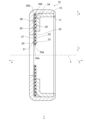
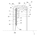
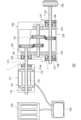
本発明の実施形態に係る導電構造体は、回転する軸に導電通路を形成するものであり、例えば、軸と軸が挿通される孔との間に導電通路を形成する。なお、本発明の実施形態に係る導電構造体が適用される適用対象は、これに限られない。図1は、本発明の第1実施形態に係る導電構造体1の概略構成を示す、軸線xを含む平面による断面を示す断面図であり、図2は、図1に示される導電構造体1の軸線xに対する一方を示す断面図である。The conductive structure according to an embodiment of the present invention forms a conductive path in a rotating shaft, for example, forming a conductive path between the shaft and a hole through which the shaft is inserted. However, the applications to which the conductive structure according to an embodiment of the present invention can be applied are not limited to this. Figure 1 is a cross-sectional view showing a cross section along a plane including axis x, showing a schematic configuration of a
図1,2に示されるように、導電構造体1は、軸線x周りに環状の導電性を有する部材である保持部材10と、軸線x周りに環状の金属材料から形成された部材である導電部材20と、軸線x周りに環状の弾性材料から形成された部材である支持部材30とを備えている。導電部材20と支持部材30とは、軸線x方向に重なって、保持部材10に保持されている。導電部材20は、軸線x周りに環状の内周側の端部である内周端部25を有しており、支持部材30は、導電部材20の内周端部25を、内周側に押圧可能に、導電部材20に重なっている。以下、導電構造体1の構成について具体的に説明する。なお、内周側は、軸線xに直交する方向(以下、径方向ともいう。)において、軸線xに近づく側であり(図1の矢印c参照)、外周側は、径方向において、軸線xから離れる側であり(図1の矢印d参照)。1 and 2, the
支持部材30は、例えば図1,2に示されるように、軸線x周りに環状の板状の部材であり、軸線x方向において互いに背向する一対の環状の面である押圧側面31と背面32とを有している。図1,2に示されるように、押圧側面31は、軸線x方向における一方の側(以下、正面側ともいう。)に面しており、背面32は、軸線x方向における他方の側(以下、背面側ともいう。)に面している。なお、図1に示されるように、正面側は、矢印a方向の側であり、背面側は、矢印b方向の側である。支持部材30は、内周側に端に環状の内周端30aを有しており、また、外周側の端に環状の外周端30bを有している。内周端30aは、内周側に支持部材30を軸線x方向に貫通する空間(貫通孔)を画成している。内周端30aは、例えば、軸線xを中心とする円に沿って延びている。外周端30bも同様に、例えば、軸線xを中心とする円に沿って延びている。
As shown in Figs. 1 and 2, for example, the
図1,2に示されるように、支持部材30は、環状の板状の部材であり、軸線xに直交する平面に沿って延びている。具体的には、支持部材30の外周端30b及びその近傍の部分である外周端部34は、軸線xに直交する平面に沿うように延びている。また、支持部材30の内周端30a及びその近傍の部分である内周端部33は、図1,2に示されるように、外周端部34から連続して、軸線xに直交する平面に沿うように延びている。なお、支持部材30の内周端部33は、軸線xに直交する平面に沿うように延びていなくてもよい。例えば、支持部材30の内周端部33は、背面32側が凹むように湾曲して、軸線x方向において背面側に向かうに連れて縮径するように湾曲していてもよい。また、支持部材30の内周端部33は、平面と曲面とが組み合わされた面に沿って延びていてもよい。支持部材30の材料は、弾性材料であり、例えば、樹脂材料やゴム材料、不織布等である。支持部材30の樹脂材料としては、例えば、PTFE(ポリテトラフルオロエチレン)、POM(ポリアセタール)、PPS(ポリフェニレンスルファイド)、PA(ポリアミド)、PEEK(ポリエーテルエーテルケトン)等がある。なお、支持部材30の材料は、これらに限られない。なお、支持部材30は、導電性を有していなくてもよく、導電性を有していてもよい。1 and 2, the
支持部材30は、上述のような構成を有しており、内周端30aが画成する空間に軸が入り、軸が内周端30aに接触した際に、例えば弾性変形して、軸の外周面に向かう(径方向に向かう)所定の大きさの押圧力が発生するようになっている。つまり、この所定の押圧力が発生するように、材料や、内周端30aの径の大きさ、内周端部33における支持部材30の厚さ等が選定されている。なお、支持部材30の厚さは、押圧側面31と背面32との間の距離である。The
導電部材20は、例えば図1,2に示されるように、軸線x周りに環状の板状の部材であり、軸線x方向において互いに背向する一対の環状の面である接触側面21と被押圧側面22とを有している。図1,2に示されるように、接触側面21は、軸線x方向における正面側に面しており、被押圧側面22は、軸線x方向における背面側に面している。導電部材20は、内周側に端に環状の内周端20aを有しており、また、外周側の端に環状の外周端20bを有している。内周端20aは、内周側に導電部材20を軸線x方向に貫通する空間(貫通孔)を画成している。内周端20aは、例えば、軸線xを中心とする円に沿って延びている。外周端20bも同様に、例えば、軸線xを中心とする円に沿って延びている。
As shown in Figs. 1 and 2, for example, the
上述したように、導電部材20と支持部材30とは、軸線x方向において重なっている。具体的には、図1,2に示されるように、導電部材20の被押圧側面22と支持部材30の押圧側面31とが対向しており、また、互いに接触している。図1,2に示されるように、導電部材20と支持部材30とは、例えば、軸線x方向に見て、互いに一致して重なるような形状となっている。つまり、導電部材20の被押圧側面22と支持部材30の押圧側面31とが、互いに同じ又は略同じ形状及び大きさとなっており、導電部材20の内周端20a及び外周端20bと支持部材30の内周端30a及び外周端30bとが、夫々互いに一致又は略一致して、導電部材20と支持部材30とが重なるようになっている。このように、導電部材20は、外周端20b及びその近傍に、支持部材30の外周端部34に対応した形状の外周端部26を有している。また、導電部材20は、内周端20a及びその近傍に、支持部材30の内周端部33に対応した内周端部25を有している。導電部材20の内周端部25は、図1,2に示されるように、支持部材30の内周端部33に対応した形状を有しており、軸線xに直交する平面に沿って延びている。なお、導電部材20の内周端部25は、平面に沿っていなくてもよい。導電部材20の内周端部25は、支持部材30の内周端部33に対応した他の形状となっていてもよい。例えば、支持部材30の内周端部33が、湾曲して延びている場合、導電部材20の内周端部25も、支持部材30の内周端部33に対応して、湾曲して延びる。As described above, the
導電部材20は、上述したように、金属製である。図1,2に示されるように、導電部材20は、導電構造体1において、支持部材30と同じ又は略同じ形状となっている。ただし、導電部材20は、柔らかく、自由状態において、支持部材30と同じ又は略同じ形状が維持されるものでなくてもよく、また、自由状態において、支持部材30と同じ又は略同じ形状が維持されるものであってもよい。例えば、導電部材20が、自由状態において、支持部材30と同じ又は略同じ形状を維持するものであった場合でも、導電部材20は、支持部材30よりも柔らかくなっており、支持部材30よりも撓みやすくなっている。なお、導電部材20の自由状態とは、単体の状態であり、導電部材20に外力が加わっていない状態である。As described above, the
導電部材20は、例えば、複数の貫通孔を有している。具体的には例えば、導電部材20は、複数の貫通孔を形成する網目構造を有している。例えば、導電部材20は、金属布である。網目構造は、接触側面21と被押圧側面22とに沿って広がっており、貫通孔は、接触側面21と被押圧側面22との間を貫通している。なお、導電部材20は、貫通孔を有していなくてもよい。The
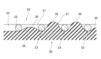
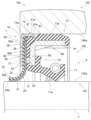
図3,4は、図1,2に示される導電部材20と支持部材30との一部を拡大して示す図であり、図3は、軸線xを含む平面による断面を示しており、図4は、正面側から見た図である。図3,4に示されるように、例えば、導電部材20は、格子状に延びる複数の金属線23によって形成されており、複数の金属線23の間に複数の貫通孔24が形成されている。なお、金属線23は、線状に延びる金属から形成された構造であり、複数の金属線23は、夫々独立した部材であってもよく、または、一体になっていてもよい。図3,4に示されるように、複数の金属線23は、接触側面21及び被押圧側面22を形成しており、被押圧側面22に支持部材30の押圧側面31が接触している。3 and 4 are enlarged views of a portion of the
図3に示されるように、例えば、支持部材30は、導電部材20の複数の貫通孔24に進入している。つまり、支持部材30の押圧側面31の複数の貫通孔24に対向する部分が、導電部材20側に突出して、この突出した部分が、複数の貫通孔24内に進入している。このように、支持部材30は、押圧側面31に、複数の突出部35を有しており、複数の突出部35は夫々、導電部材20の複数の貫通孔24内に進入している。図3に示されるように、支持部材30の突出部35は、導電部材20の接触側面21まで達したおらず、貫通孔24の途中まで突出しているものであってもよい。また、支持部材30の突出部35は、導電部材20の接触側面21まで達しているものであってもよい。つまり、支持部材30の突出部35は、貫通孔24の接触側面21側の端まで突出しているものであってもよく、または、貫通孔24の接触側面21側の端を超えて突出しているものであってもよい。なお、支持部材30の押圧側面31の貫通孔24に対向する部分に、突出部35が形成されていなくてもよい。3, for example, the
導電部材20と支持部材30とは、夫々別に作られたものを重ね合わせてもよく、インサート成形により、導電部材20と支持部材30とを一体成形してもよい。夫々別に作られた導電部材20と支持部材30とを重ね合わせる場合、プレス等により、支持部材30の押圧側面31に複数の突出部35を形成することができる。支持部材30の押圧側面31に突出部35を形成しない場合、例えば、導電部材20と支持部材30とを重ねて、保持部材10に保持させる。なお、導電部材20と支持部材30とを互いに接着させてもよい。The
図1,2に示されるように、保持部材10は、具体的には、内側に位置する内保持部材11と、外側に位置する外保持部材15とを有している。内保持部材11と外保持部材15とは、軸線x周りに環状の部材であり、互いの間に導電部材20と支持部材30とを重ねて保持可能な形態となっている。1 and 2, the holding
図2に示されるように、内保持部材11は、例えば、軸線x周りに環状の部分である嵌合部12と、軸線x周りに環状の部分である保持部13とを有している。嵌合部12は、軸線xに沿って延びる筒状の部分であり、保持部13は、嵌合部12の正面側の端部から内周側に延びる円環状の部分である。嵌合部12は、例えば、軸線xを中心軸又は略中心軸とする円筒状又は略円筒状になっている。2, the inner retaining
図2に示されるように、外保持部材15は、例えば、軸線x周りに環状の部分である嵌合部16と、軸線x周りに環状の部分である保持部17とを有している。嵌合部16は、軸線xに沿って延びる筒状の部分であり、保持部17は、嵌合部16の正面側の端部から内周側に延びる円環状の部分である。嵌合部16は、例えば、軸線xを中心軸又は略中心軸とする円筒状又は略円筒状になっている。2, the outer retaining
図1,2に示されるように、内保持部材11と外保持部材15とは互いに嵌合されるようになっている。具体的には例えば、内保持部材11の嵌合部12の外周面12aの径が、外保持部材15の嵌合部16の内周面16aの径よりも大きくなっており、外保持部材15の嵌合部16の内周側に内保持部材11の嵌合部12が圧入されて、内保持部材11の嵌合部12と外保持部材15の嵌合部16とは互いに嵌合されるようになっている。なお、嵌合部12の外周面12aは、嵌合部12の外周側に面する環状の面であり、また、嵌合部16の内周面16aは、嵌合部16の内周側に面する環状の面である。また、図1,2に示されるように、内保持部材11の嵌合部12と外保持部材15の嵌合部16とが互いに嵌合された状態において、内保持部材11の保持部13と、外保持部材15の保持部17とは、軸線x方向において対向する部分を有するようになっている。1 and 2, the inner holding
また、図1,2に示されるように、内保持部材11と外保持部材15とが互いに嵌合された状態において、内保持部材11の保持部13と、外保持部材15の保持部17とは、軸線x方向において、互いに重ねられた導電部材20及び支持部材30に対向するようになっている。具体的には、支持部材30の外周端部34における背面32が、内保持部材11の保持部13に対向し、導電部材20の外周端部26における接触側面21が、外保持部材15の保持部17に対向するようになっている。なお、図1,2に示されるように、導電部材20及び支持部材30夫々の内周端部25及び内周端部33は、内保持部材11の保持部13よりも内周側に位置し、また、外保持部材15の保持部17よりも内周側に位置するようになっている。1 and 2, when the inner holding
図2に示されるように、内保持部材11と外保持部材15とが嵌合されて、互いに重ねられた導電部材20と支持部材30とが夫々外周端部26及び外周端部34において、内保持部材11の保持部13と外保持部材15の保持部17との間に挟まれて軸線x方向に押圧された状態で、外保持部材15の嵌合部16に押さえ部18が形成され、内保持部材11は、外保持部材15に対して固定される。なお、外保持部材15の押さえ部18は、内保持部材11の嵌合部12に接触して、嵌合部12を軸線x方向において固定する部分である。このように、互いに重ねられた導電部材20と支持部材30とは、内保持部材11と外保持部材15との間に固定された状態(以下、「組立状態」ともいう。)になる。2, when the inner holding
内保持部材11及び外保持部材15は、導電性を有する金属から作られている。なお、内保持部材11及び外保持部材15は、他の導電性を有する材料から形成されていてもよい。The
導電構造体1の各構成部材は、上述のような構成を有しており、組み立てられて組立状態になり、図1,2に示されるような導電構造体1となる。導電構造体1において、内保持部材11の嵌合部12が外保持部材15の嵌合部16に嵌合されており、また、内保持部材11の嵌合部12は、外保持部材15の嵌合部16の押さえ部18によって、正面側に向かって押されている。また、互いに重ね合わされた導電部材20と支持部材30とは、内保持部材11の保持部13と外保持部材15の保持部17との間に挟まれている。導電部材20及び支持部材30は夫々、外周端部26及び外周端部34において内保持部材11及び外保持部材15に保持されている。このように、内保持部材11は外保持部材15に固定されており、導電部材20及び支持部材30は、内保持部材11と外保持部材15との間に固定されている。また、導電部材20及び支持部材30は夫々、後述する使用状態において軸に導電部材20の接触側面21が接触するように、内保持部材11及び外保持部材15に取り付けられている。なお、図1,2に示されるように、導電部材20及び支持部材30は夫々、導電部材20の接触側面21が正面側に向くように、内保持部材11及び外保持部材15に取り付けられているが、導電部材20及び支持部材30は夫々、導電部材20の接触側面21が背面側に向くように、内保持部材11及び外保持部材15に取り付けられていてもよい。Each component of the
図1,2に示されるような組立状態になる前に、外保持部材15の嵌合部16は、押さえ部18を有していなくてもよい。例えば、嵌合部16に押さえ部18が形成されていない外保持部材15に、互いに重ね合わされた導電部材20及び支持部材30を取り付け、その後、外保持部材15の嵌合部16に内保持部材11の嵌合部12を取り付けた後に、嵌合部16に押さえ部18を形成してもよい。つまり、押さえ部18を形成することにより、嵌合部12と嵌合部16とをかしめて、押さえ部18によって嵌合部12の端を正面側に押圧するようにして、導電部材20、支持部材30、内保持部材11、及び外保持部材15を、図1,2に示されるように、組立状態にしてもよい。1 and 2, the
次いで、導電構造体1の作用について説明する。図5は、導電構造体1の適用対象の一例を示すための概念図である。図6は、図5に示される適用対象における、導電構造体1の使用状態の一例を示す断面図である。導電構造体1は、一例として、図5に示されるように、バッテリー電気自動車(BEV)の駆動装置100に適用される。駆動装置100は、例えば図5に示されるように、電動モータ101、減速機102、電動モータ101を制御するインバータ103、及び電源としてのバッテリー104を有している。電動モータ101において、軸110は、ハウジング111内に支持されたベアリング112に回転可能に支持されており、また、ハウジング111の軸孔113を通ってハウジング111の外に出ている。電動モータ101の軸110は、減速機102のハウジング120の軸孔124を通ってハウジング120内に入っており、ハウジング120内に支持されたベアリング123に回転可能に支持されている。また、軸110は、ハウジング120内の減速ギア段121に接続している。また、減速機102には、減速ギア段121によって減速された回転駆動力を出力する軸122が設けられている。軸122は、ハウジング120内に支持されたベアリング123に回転可能に支持されており、また、車輪105に接続して、車輪105に回転駆動力を伝達可能になっている。減速機102のハウジング120の軸孔124には、軸孔124と電動モータ101の軸110との間の隙間を密閉するためのオイルシール125が取り付けられている。減速機102の軸122が通るハウジング120の軸孔126には、軸孔126と軸122との間の隙間を密閉するためのオイルシール127が取り付けられている。なお、電動モータ101の軸110及びハウジング111は、金属製であり、減速機102のハウジング120及び軸122は、金属製である。Next, the function of the
導電構造体1は、一例として、電動モータ101のハウジング111と軸110との間に設けられて、使用状態になる。具体的には、図6に示されるように、保持部材10の外保持部材15の嵌合部16がハウジング111の軸孔113に嵌着されて、導電構造体1が軸孔113に固定され、また、軸110が導電部材20及び支持部材30に挿入されて、導電構造体1は使用状態になる。使用状態において、導電部材20の内周端部25における接触側面21は、軸110の外周面110aに接触しており、また、導電部材20の内周端部25は、軸110に外周側に押されて変形している。図6に示されるように、導電部材20の内周端部25は、軸線x方向に幅を持って、軸110の外周面110aに接触している。また、導電部材20が取り付けられた保持部材10(内保持部材11及び外保持部材15)は導電性を有する金属で作られており、ハウジング111の軸孔113の内周面113aに接触している。このように、導電部材20と保持部材10とは、使用状態において、電動モータ101の軸110とハウジング111との間に電気を流す導電通路を形成している。
As an example, the
また、図6に示されるように、支持部材30が背面側から導電部材20に重なっており、導電部材20の被押圧側面22に支持部材30の押圧側面31が接触している。上述のように、使用状態において、導電部材20の内周端部25は、軸110から外周側の反力を受けて変形しており、支持部材30の内周端部33も、導電部材20の内周端部25を介して、軸110から外周側の反力を受けて変形している。支持部材30の内周端部33は、上述のように弾性を有しているため、支持部材30の内周端部33は弾性変形しており、支持部材30の内周端部33には、軸110から受ける力に対する反力が発生している。この支持部材30の反力によって、導電部材20は、軸110の外周面110aに押し付けられており、導電部材20の接触側面21は、軸110に向かって押圧されて、軸110の外周面110aに接触している。6, the
このように、使用状態において、導電部材20は、支持部材30の反力によって、軸110の外周面110aに押し付けられており、導電部材20と軸110との間の接触が強固なものになっている。また、導電部材20の内周端部25の軸110に対する追従性が向上されており、この点においても、導電部材20と軸110との間の接触が強固なものになっている。このように、導電構造体1においては、導電部材20と軸110との間の接触が安定したものになっている。このため、電動モータ101の軸110とハウジング111との間の導電通路を、電気を安定して流す導電通路とすることができる。In this way, in the use state, the
また、図3,4に示されるように、導電部材20の複数の貫通孔24内に、支持部材30の押圧側面31に形成された突出部35が進入しており、この突出部35が導電部材20の接触側面21を超えて突出している場合、導電部材20に加えて、この支持部材30の突出部35も軸110の外周面110aに接触する。支持部材30が樹脂製部材等の金属製部材よりも潤滑性能の高い部材である場合、貫通孔24から飛び出した突出部35が軸110に接触することにより、導電部材20に対して摺動する軸110に対し、潤滑効果が付与される。このため、導電部材20に対する軸110の摺動が滑らかになり、導電部材20の摩耗を抑制することができる。また、突出部35が貫通孔24から飛び出していない場合であっても、導電部材20の摩耗により、突出部35が貫通孔24から飛び出した際に、突出部35は軸110に接触し、導電部材20に対して摺動する軸110に対し、潤滑効果を付与することができる。このように、支持部材30の押圧側面31に形成された突出部35は、導電部材20の耐摩耗性を向上させることができる。3 and 4, when the
また、使用状態において、導電部材20は、支持部材30によって支持されて、軸110に安定して接触するようになっている。このため、導電部材20の剛性を低くすることができる。また、導電部材20は、複数の貫通孔24を有する網目構造を有しており、導電部材20の剛性は、この構成によっても低くされている。このため、導電部材20の軸110に対する接触を滑らかな接触にすることができる。これにより、導電部材20の耐摩耗性を向上させることができる。導電部材20の剛性は、貫通孔24の数や金属線23の線径の設定や、導電部材20を作る金属材料の種類等によって調整することができる。また、導電部材20に切り込みを入れることによっても導電部材20の剛性を調整することができる。In addition, in a state of use, the
また、導電構造体1は、減速機102のハウジング120と軸122との間に設けられてもよい。具体的には、図5に示されるように、オイルシール127の外側において、ハウジング120の軸孔126と軸122との間の隙間に、導電構造体1が設けられてもよい。この場合も電動モータ101に取り付けられた導電構造体1と同様に、導電構造体1の導電部材20及び支持部材30と保持部材10とは、減速機102の軸122とハウジング120との間に電気を流す導電通路を形成する。The
なお、上述の駆動装置100は、導電構造体1の適用対象の一例であり、導電構造体1の適用対象はこれに限られない。導電構造体1は、例えば、バッテリー電気自動車(BEV)の他の、ハイブリッド自動車(HV)、燃料電池自動車(FCV)等の電気自動車(EV)等の駆動装置に用いられる。電気自動車(EV)等の電動モータが搭載されている車両では、モータから発生する誘導電流等によって電磁波ノイズが発生することがある。また、電動モータ等の電動機に供給する電流制御用のインバータのオンオフ動作、あるいは電動機自身の誘導電圧等によって電磁波ノイズが発生することがある。上述のように、導電構造体1は導電通路を形成し、軸110,122に伝達された電磁波ノイズをハウジング111,120に流す。これによって電子機器に通信障害や誤動作が発生すること、ベアリング等の金属部品に電食が発生することを防止することができる。
The above-mentioned
上述のように、導電構造体1は、導電部材20の耐摩耗性を向上させることができる。このため、導電部材20の摩耗やへたりを抑制するために、導電部材20と軸110,122との間に導電性を有する潤滑剤を設けなくてもよい。このため、軸110,122とハウジング111,120との間の導電通路に、導電通路の抵抗となり得る潤滑剤はなく、使用状態において導電構造体1の導電性能が低下することを抑制できる。As described above, the
また、導電構造体1は、例えば図6に示されるように、保持部材10をハウジング111の軸孔113に嵌着させることにより、軸110の周りに取り付けることができる。このように、導電構造体1の取り付けには、軸110の外周面110aを囲む環状のスペースのみが必要である。軸110の外周面110aと軸孔113の内周面113aとの間に導電構造体1を取り付けるスペースがある場合は、軸孔113に導電構造体1を取り付けられるので、ハウジング111に導電構造体1を取り付けのためのスペースを追加で設ける必要はない。また、軸110の外周面110aと軸孔113の内周面113aとの間に導電構造体1を取り付けるスペースがない場合であっても、導電構造体1の断面は大きくないため、導電構造体1を取り付けのために、小さな環状のスペースを軸孔113の内周面113aに設けるだけでよい。このように、導電構造体1は、導電構造体1が取り付けられるスペースを小さくすることができ、省スペースを可能にできる。
The
上述のように、本発明の第1実施形態に係る導電構造体1は、導電性を有しつつ耐摩耗性を向上することができる。As described above, the
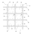
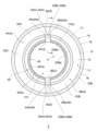
次いで、本発明の第2実施形態に係る導電構造体2について説明する。図7は、本発明の第2実施形態に係る導電構造体2の背面図であり、図8は、図7の線A-Aに沿う断面の軸線xに対する一方を示す断面図である。図7には、軸110が挿入された使用状態における状態で導電構造体2が示されており、図8には、軸110が挿入されていない組立状態で導電構造体2が示されている。なお、図8において、カッコ内の符号は、断面の反対側の構成を示している。導電構造体2は、上述の導電構造体1に対して、導電部材及び支持部材の構成が異なる。以下、導電構造体2の構成について、上述の導電構造体1と同じ構成又は同様の機能を有する構成については、同じ符号を付してその説明を省略し、導電構造体1と異なる構成について説明する。Next, the
図7,8に示されるように、導電構造体2は、導電構造体1の導電部材20及び支持部材30とは夫々異なる導電部材40及び支持部材50を有している。導電構造体2においても、導電部材40と支持部材50とは、導電構造体1の導電部材20及び支持部材30と同様に重ねられて保持部材10に保持される。7 and 8, the
図7,8に示されるように、導電構造体2において、重ねられた導電部材40及び支持部材50は、少なくとも1つの径方向に延びるように設けられた隙間3と、少なくとも1つの軸線x周りに延びる分割体4とを有している。分割体4は、軸線x周りの方向に一対の端4a,4bを有している。隙間3は、分割体4の端4a,4bに連なっている。7 and 8, in the
図7,8に示されるように、重ねられた導電部材40及び支持部材50は、例えば、導電構造体2において、2つの隙間3(隙間3A,3B)と2つの分割体4(分割体4A,4B)とから構成された、環状の板状の構造体となっている。図7,8に示されるように、分割体4Aは、一対の端4a,4bとしての一対の端4Aa,4Abを有しており、分割体4Bは、一対の端4a,4bとしての一対の端4Ba,4Bbを有している。分割体4の一方(分割体4A)の一対の端の一方(端4Aa)と、分割体4の他方(分割体4B)の一対の端の一方(4Ba)とは、軸線x周りの方向(周方向)において対向している。また、分割体4Aの一対の端の他方(端4Ab)と、分割体4Bの一対の端の他方(端4Bb)とは、軸線x周りの方向(周方向)において対向している。分割体4Aの端4Aaと、分割体4Bの端4Baとの間に、隙間3の一方(隙間3A)が形成されており、分割体4Aの端4Abと、分割体4Bの端4Bbとの間に、隙間3の他方(隙間3B)が形成されている。
As shown in Figures 7 and 8, the overlapped
分割体4A,4Bは、図1~4に示される、導電構造体1の重ねられた導電部材20及び支持部材30の一部に対応する部材であり、分割体4A,4Bは夫々、導電構造体1の重ねられた導電部材20及び支持部材30の一部に一致又は略一致する。分割体4A,4Bは、例えば、図1~4に示される、重ねられた導電部材20及び支持部材30を、隙間3A,3Bを形成するように分割することにより形成される。なお、このため、分割体4A,4Bの軸線xを含む平面による断面の形状は、図2に示される導電構造体1の重ねられた導電部材20及び支持部材30の断面形状と同じである(図8参照)。The divided
図8に示されるように、分割体4Aは、導電部材片20Aと支持部材片30Aとを有している。導電部材片20Aは、導電構造体1の導電部材20の一部に対応する部材であり、支持部材片30Aは、導電構造体1の支持部材30の一部に対応する部材である。また、分割体4Bは、導電部材片20Bと支持部材片30Bとを有している。導電部材片20Bは、導電構造体1の導電部材20の一部に対応する部材であり、支持部材片30Bは、導電構造体1の支持部材30の一部に対応する部材である。このため、導電部材片20Aは、導電部材20と同じ断面形状を有しており、また、導電部材20の内周端20a、外周端20b、接触側面21、被押圧側面22、内周端部25、及び外周端部26夫々の一部に対応する、内周端20Aa、外周端20Ab、接触側面21A、被押圧側面22A、内周端部25A、及び外周端部26Aを有している。また、導電部材片20Aは、導電部材20と同様に構成されており、例えば、複数の金属線23及び複数の貫通孔24を有している。同様に、導電部材片20Bは、導電部材20と同じ断面形状を有しており、また、導電部材20の内周端20a、外周端20b、接触側面21、被押圧側面22、内周端部25、及び外周端部26夫々の一部に対応する、内周端20Ba、外周端20Bb、接触側面21B、被押圧側面22B、内周端部25B、及び外周端部26Bを有している。また、導電部材片20Bは、導電部材20と同様に構成されており、例えば、複数の金属線23及び複数の貫通孔24を有している。As shown in Figure 8, the divided
また、支持部材片30Aは、支持部材30と同じ断面形状を有しており、また、支持部材30の内周端30a、外周端30b、押圧側面31、背面32、内周端部33、及び外周端部34夫々の一部に対応する、内周端30Aa、外周端30Ab、押圧側面31A、背面32A、内周端部33A、及び外周端部34Aを有している。同様に、支持部材片30Bは、支持部材30と同じ断面形状を有しており、また、支持部材30の内周端30a、外周端30b、押圧側面31、背面32、内周端部33、及び外周端部34夫々の一部に対応する、内周端30Ba、外周端30Bb、押圧側面31B、背面32B、内周端部33B、及び外周端部34Bを有している。また、支持部材片30A,30Bは、支持部材30と同様に、複数の凸部35を有している。In addition, the
分割体4Aにおいて、導電部材片20Aと支持部材片30Aとは、導電部材20と支持部材30と同様に重なっている。具体的には、導電部材片20Aの被押圧側面22Aと支持部材片30Aの押圧側面31Aとが接触している。また、導電部材片20Aの被押圧側面22Aと支持部材片30Aの押圧側面31Aとが、互いに同じ又は略同じ形状及び大きさとなっており、導電部材片20Aの内周端20Aa及び外周端20Abと支持部材片30Aの内周端30Aa及び外周端30Abとが、夫々互いに一致又は略一致している。導電部材片20Aは、一対の周方向の端である端20Ac,20Adを有しており、また、支持部材片30Aは、一対の周方向の端である端30Ac,30Adを有している。導電部材片20Aの端20Acと支持部材片30Aの端30Acとは、重なって、分割体4Aの端4Aaを形成しており、導電部材片20Aの端20Adと支持部材片30Aの端30Adとは、重なって、分割体4Aの端4Abを形成している。In the divided
同様に、分割体4Bにおいて、導電部材片20Bと支持部材片30Bとは、導電部材20と支持部材30と同様に重なっている。具体的には、導電部材片20Bの被押圧側面22Bと支持部材片30Bの押圧側面31Bとが接触している。また、導電部材片20Bの被押圧側面22Bと支持部材片30Bの押圧側面31Bとが、互いに同じ又は略同じ形状及び大きさとなっており、導電部材片20Bの内周端20Ba及び外周端20Bbと支持部材片30Bの内周端30Ba及び外周端30Bbとが、夫々互いに一致又は略一致している。導電部材片20Bは、一対の周方向の端である端20Bc,20Bdを有しており、また、支持部材片30Bは、一対の周方向の端である端30Bc,30Bdを有している。導電部材片20Bの端20Bcと支持部材片30Bの端30Bcとは、重なって、分割体4Bの端4Baを形成しており、導電部材片20Bの端20Bdと支持部材片30Bの端30Bdとは、重なって、分割体4Bの端4Bbを形成している。Similarly, in the divided
上述のように、分割体4A,4Bは夫々、重ねられた導電部材20及び支持部材30の一部に対応する部材であり、図7に示されるように、軸線x周りの円弧に沿って延びる板状の部材である。分割体4A,4Bは、例えば、軸線xを中心又は略中心とする円弧又は略円弧に沿って延びている。具体的には例えば、図7に示されるように、分割体4A,4Bは、分割体4A,4Bが沿って延びる円の半円よりも短くなるように、周方向に延びている。つまり、分割体4A(導電部材片20Aと支持部材片30A)の端4Aa及び端4Abが共に、軸線xを含む1つの平面上に位置する、または、軸線xを含む1つの平面を超える、ことがないようなに、分割体4Aは周方向に延びている。図7に示されるように、分割体4Aの端4Aa,4Abは、例えば、軸線xを含む平面に平行に又は略平行に延びており、軸線xに直交する方向に面している。なお、分割体4Aの端4Aa,4Abは、軸線xを含む平面に平行に延びていなくてもよい。As described above, the divided
分割体4B(導電部材片20Bと支持部材片30B)は、分割体4Aと同様の形状を有しており、分割体3Bの端4Ba及び端4Bbが共に、軸線xを含む1つの平面上に位置する、または、軸線xを含む1つの平面を超える、ことがないようなに、分割体4Bは周方向に延びている。図7に示されるように、分割体4Bの端4Ba,4Bbは、例えば、軸線xを含む平面に平行に又は略平行に延びており、軸線xに直交する方向に面している。なお、分割体4Bの端4Ba,4Bbは、軸線xを含む平面に平行に延びていなくてもよい。なお、分割体4Bは、分割体4Aと同様に形成されていなくてもよく、分割体4Aと同じ形態を有していなくてもよい。The divided
上述したように、導電部材40は、導電部材片20A,20Bを有しており、また、支持部材50は、支持部材片30A,30Bを有している。また、分割体4Aは、導電部材片20Aと支持部材片30Aが互いに重ねられて形成されており、また、分割体4Bは、導電部材片20Bと支持部材片30Bが互いに重ねられて形成されている。図7に示されるように、導電構造体2において、各構成要素である分割体4A,4B及び隙間3A,3Bは、軸線xを中心又は略中心とする円又は略円上に位置している。具体的には、例えば、分割体4Aと分割体4Bとは、軸線xを含む平面について対称となるように配置されている。また、導電部材片20Aの内周端20Aaと、導電部材片20Bの内周端20Baとが、軸線xを中心又は略中心とする円又は略円上に位置するように、分割体4Aと分割体4Bとは配置されている。分割体4Aの端4Aaと分割体4Bの端4Baとは、軸線xに直交する方向において互いに対向しており、分割体4Aの端4Abと分割体4Bの端4Bbとは、軸線xに直交する方向において互いに対向している。これにより、分割体4Aの端4Aaと分割体4Bの端4Baとの間に隙間3Aが形成されており、また、分割体4Aの端4Abと分割体4Bの端4Bbとの間に隙間3Bが形成されている。このように、隙間3Aは、分割体4Aの端4Aaと分割体4Bの端4Baとに連なっており、隙間3Bは、分割体4Aの端4Abと分割体4Bの端4Bbとに連なっている。As described above, the
導電構造体2も、上述の導電構造体1と同様に使用されて、電動モータ101の軸110とハウジング111との間に導電通路を形成する。また、導電構造体2も、上述の導電構造体1と同様に作用して、同様の効果を奏する。The
また、導電構造体2においては、分割体4A,4Bは、隙間3A,3Bを介して環状に並べられている。このため、使用状態において、軸110の回転によって分割体4A,4Bに外力が加わったとしても、分割体4A,4Bは、隙間3A,3Bに逃げることができる。このため導電部材片20A,20Bや支持部材片30A,30Bに、応力集中が発生するような変形や軸110への接触が、導電部材片20A,20Bや支持部材片30A,30Bに生じることを抑制できる。これにより、導電部材片20A,20Bの摩耗や、導電部材片20A,20Bや支持部材片30A,30Bのへたりを抑制することができる。In addition, in the
また、導電構造体2において、分割体4A,4Bは、隙間3A,3Bを介して環状に並べられている。このため、導電部材片20A,20Bや支持部材片30A,30Bを保持部材10に固定する際に、導電部材片20A,20Bや支持部材片30A,30Bは、隙間3A,3Bに逃げることができる。これにより、導電部材片20A,20Bや支持部材片30A,30Bを保持部材10に固定する際に、導電部材片20A,20Bや支持部材片30A,30Bにしわ等の変形が生じることを抑制できる。In addition, in the
なお、図7,8に示されるように、外保持部材15の保持部17の側面17aには、例えば、分割体4A,4Bの隙間3A,3B夫々に対応する周方向の位置に、背面側に突出する部分である凸部5a,5bが設けられていてもよい。導電構造体2において、凸部5aは、隙間3Aに収容され、凸部5bは、隙間3Bに収容される。隙間3Aにおいて、凸部5aは、分割体4Aの端4Aa及び分割体4Bの端4Baに接触するようになっており、隙間3Bにおいて、凸部5bは、分割体4Aの端4Ab及び分割体4Bの端4Bbに接触するようになっている。なお、隙間3Aにおいて、凸部5aと分割体4Aの端4Aaとの間には隙間が形成されていてもよい。また、隙間3Aにおいて、凸部5aと分割体4Bの端4Baとの間には隙間が形成されていてもよい。同様に、隙間3Bにおいて、凸部5bと分割体4Aの端4Abとの間には隙間が形成されていてもよい。また、隙間3Bにおいて、凸部5bと分割体4Bの端4Bbとの間には隙間が形成されていてもよい。なお、凸5a,5bは、外保持部材15の保持部17の側面17aではなく、内保持部材11の保持部13の側面13aに、同様に夫々隙間3A,3Bに収容されるように設けられていてもよい。また、凸部5a,5bは、外保持部材15の保持部17の側面17aに加えて、内保持部材11の保持部13の側面13aにも設けられていてもよい。また、凸部5aは、複数設けられていてもよい。また、凸部5bは、複数設けられていてもよい。凸部5a,5bは、分割体4A,4Bの保持部材10に対する回転の防止を図ることができる。7 and 8, the
上述のように、本発明の第2実施形態に係る導電構造体2は、導電性を有しつつ耐摩耗性を向上することができる。As described above, the
次いで、上述の導電構造体2の変形例について説明する。図9は、導電構造体2の変形例を示すための背面図であり、変形例に係る分割体4Cが示されている。図9に示されるように、変形例に係る導電構造体2は、分割体4として1つの分割体4Cと、隙間3として1つの隙間3Cとを有しているものである。変形例に係る導電構造体2には、隙間3A又は隙間3Bの一方がなく、隙間3A又は隙間3Bの一方の部分にも分割体4A又は分割体4Bが延びており、隙間3A又は隙間3Bの一方の部分において分割体4Aと分割体4Bとがつながって1つの分割体4Cとなっているものである。変形例に係る導電構造体2の分割体4Cは、図9に示されるように例えば、軸線xを中心又は略中心とする円又は略円上に延びており、端4Caと端4Cbとは、周方向において対向しており、具体的には例えば、軸線xに直交する方向において対向している。分割体4Cは、分割体4A,4Bと同様に、導電構造体1の導電部材20の一部に対応する部材である導電部材片20Cと、導電構造体1の支持部材30の一部に対応する部材である支持部材片30Cとを有している。なお、導電構造体2は、3つ以上の隙間3及び3つ以上の分割体4を有していてもよい。この場合も、複数の隙間3及び複数の分割体4は、環状に連なっている。本変形例においては、凸部5a,5bの一方のみが設けられている。Next, a modified example of the
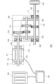
次いで、本発明の第1実施形態に係る導電密封装置6について説明する。図10は、導電密封装置6の概略構成を示す、導電密封装置6の軸線xを含む平面による断面の軸線xに対する一方を示す断面図である。導電密封装置6は、適用対象の軸と軸が通る孔との間の密封を図るための密封装置であって、また、軸と軸が通る孔との間に導電通路を形成する導電構造体である。Next, the
図10に示されるように、導電密封装置6は、軸線x周りに環状の部材である補強環60と、補強環60に取り付けられている軸線x周りに環状の弾性体から形成された弾性体部70と、軸線x周りに環状の導電構造体7とを備えている。弾性体部70は、軸に接触するシールリップ71を有している。導電構造体7は、軸線x周りに環状の部材である保持部材80と、上述の導電部材20及び支持部材30とを有している。導電部材20と支持部材30とは、上述の導電構造体1における導電部材20と支持部材30と同様に重なって、保持部材80に保持されている。以下、導電密封装置6の構成について具体的に説明する。As shown in FIG. 10, the
図10に示されるように、導電密封装置6は、例えば、公知のオイルシールと同様の補強環60及び弾性体部70を有しており、補強環60は、筒部61と円環部62とを有している。また、弾性体部70は、シールリップ71に加えて、基部72、ガスケット部73、及びカバー部74を有している。シールリップ71は基部72から密封対象物側に向かって延びている。ガスケット部73は、補強環60の筒部61を外周側から覆う部分であり、適用対象の孔に圧入される部分である。ガスケット部73の外周面73aは、適用対象の孔に押し付けられるような径になっている。カバー部74は、補強環60の円環部62を、密封対象物側と反対側から覆う部分である。10, the
図10に示されるように、カバー部74の外周側の端部(外周端部74a)には、外周側に面する環状の面である嵌合面75が形成されている。嵌合面75は、例えば、軸線xを中心軸とする円筒面に沿って延びる筒面である。嵌合面75は、具体的には例えば、軸線xを中心軸又は略中心軸とする円筒面又は略円筒面である。嵌合面75は、例えば図10に示されるように、外周端部74aの他の部分よりも外周側に位置しており、ガスケット部73との間に内周側に凹む環状の凹部76が形成されている。カバー部74の嵌合面75は、ガスケット部73の外周面73aよりも径方向において内周側に位置している。10, the outer peripheral end (outer
また、カバー部74は、密封対象物側と反対側に面する環状の面である保持面77を有している。保持面77は、例えば、軸線xに直交する平面に沿って延びる面である。保持面77は、具体的には例えば、軸線xに直交する平面に平行又は略平行な面上を延びる面である。In addition, the
導電構造体7の保持部材80は、図10に示されるように、上述の導電構造体1の保持部材10の外保持部材15と同様の形態を有している。保持部材80は、外保持部材15と同じ導電性の材料から作られている。図10に示されるように、保持部材80は、例えば、軸線x周りに環状の部分である嵌合部81と、軸線x周りに環状の部分である保持部82とを有している。嵌合部81は、軸線xに沿って延びる筒状の部分であり、保持部82は、嵌合部81の正面側の端部から内周側に延びる円環状の部分である。図10に示されるように、嵌合部81は、例えば、径方向において互いに背向する面である外周面81aと内周面81bとを有している。外周面81aは、外周側に面する環状の面であり、内周面81bは、内周側に面する環状の面である。内周面81bは、軸線xに沿って延びる筒面であり、例えば、軸線xを中心軸又は略中心軸とする円筒面又は略円筒面である。また、図10に示されるように、保持部82は、例えば、軸線x方向において互いに背向する面である側面82a,82bを有している。嵌合部81の内周面81bにつながる側面82bは、軸線xに直交する平面に沿って延びており、例えば、軸線xに直交する平面に平行又は略平行な面上に延びている。
As shown in FIG. 10, the holding
保持部材80の嵌合部81は、弾性体部70のカバー部74の外周端部74aに嵌合可能になっている。具体的には例えば、嵌合部81の内周面81bの径が、カバー部74の外周端部74aの嵌合面75の径よりも小さくなっている。これにより、保持部材80の嵌合部81内に、弾性体部70のカバー部74が圧入されて、保持部材80が弾性体部70に固定されるようになっている。The
図10に示されるように、重ねられた導電部材20及び支持部材30は、保持部材80の保持部82と弾性体部70のカバー部74の保持面77との間に保持されている。具体的には、支持部材30の外周端部34における背面32に、保持部材80の側面82bが接触して、導電部材20の外周端部25をカバー部74の保持面77に押し付けている。上述のように、保持部材80の嵌合部81が、弾性体部70のカバー部74の外周端部74aに嵌合されて、保持部82が支持部材30及び導電部材20をカバー部74の保持面77に押し付けた状態で、保持部材80が弾性体部70に固定されている。なお、保持部材80の嵌合部81の端部81cに、カバー部74の凹部76に収容される凸部83を設けてもよい(図10参照)。上述のように、保持部材80の嵌合部81が、弾性体部70のカバー部74の外周端部74aに嵌合された際に、凸部83が凹部76に収容されるようにすることにより、保持部82が支持部材30及び導電部材20をカバー部74の保持面77に押し付けた状態で、保持部材80をより強固に弾性体部70に固定させることができる。10, the overlapped
導電密封装置6において、上述の導電構造体1における導電部材20及び支持部材30と同様に、導電部材20の被押圧側面22に支持部材30の押圧側面31が接触して、支持部材30が導電部材20を支持している。これにより、導電密封装置6においても、導電部材20の内周端部25における接触側面21は、適用対象の軸の外周面に接触するようなっている。In the
導電密封装置6の各構成部材は、上述のような構成を有しており、組み立てられて組立状態になり、図10に示されるような導電密封装置6となる。導電密封装置6において、保持部材80の嵌合部81が弾性体部70のカバー部74の外周端部74aに嵌合されており、重ねられた導電部材20及び支持部材30は、保持部材80の保持部82と弾性体部70のカバー部74との間に挟まれている。このように、保持部材80は弾性体部70に固定されており、導電部材20と支持部材30とは、保持部材80と弾性体部70との間に固定されている。Each component of the
図11は、導電密封装置6の適用対象の一例を示すための概念図である。図12は、図11に示す適用対象における、導電密封装置6の使用状態の一例を示す断面図である。導電密封装置6は、一例として、図11に示されるように、バッテリー電気自動車(BEV)の駆動装置200に適用される。駆動装置200は、上述の駆動装置100(図5,6参照)と同様の構成を有しているが、駆動装置100に対して、導電構造体1が取り付けられない点で異なる。また、駆動装置200には、駆動装置100のオイルシール127に変えて、導電密封装置6が取り付けられている。導電密封装置6は、一例として、減速機102のハウジング120と軸122との間に設けられて、使用状態になる。具体的には、弾性体部70のガスケット部73がハウジング120の軸孔126に嵌着されて、導電密封装置6が軸孔126に固定され、また、軸122がシールリップ71並びに導電部材20及び支持部材30に挿入されて、導電密封装置6は使用状態になる。使用状態において、シールリップ71は軸122の外周面122aに接触して、密封対象物側が密封される。また、使用状態において、導電部材20は支持部材30に支持されて、導電部材20の内周端部25における接触側面21は、軸122の外周面122aに接触している。また、導電部材20を保持する保持部材80は導電性を有する金属で作られており、ハウジング120の軸孔126の内周面126aに接触している。このように、導電部材20と保持部材80とは、使用状態において、軸122とハウジング120との間に電気を流す導電通路を形成している。
Figure 11 is a conceptual diagram showing an example of an application target of the
なお、上述の駆動装置200は、導電密封装置6の適用対象の一例であり、導電密封装置6の適用対象はこれに限られない。導電密封装置6は、例えば、バッテリー電気自動車(BEV)の他の、ハイブリッド自動車(HV)、燃料電池自動車(FCV)等の電気自動車(EV)等の駆動装置に用いられる。電気自動車(EV)等の電動モータが搭載されている車両では、モータから発生する誘導電流等によって電磁波ノイズが発生することがある。また、電動モータ等の電動機に供給する電流制御用のインバータのオンオフ動作、あるいは電動機自身の誘導電圧等によって電磁波ノイズが発生することがある。上述のように、導電密封装置6は導電通路を形成し、軸110,122に伝達された電磁波ノイズをハウジング120に流す。これによって電子機器に通信障害や誤動作が発生すること、ベアリング等の金属部品に電食が発生することを防止することができる。
The above-mentioned
導電密封装置6の導電構造体7も、上述の導電構造体1と同様に使用されて、導電構造体1と同様に作用し、同様の効果を奏する。The
なお、導電構造体7は、導電部材20及び支持部材30に変えて、導電部材40及び支持部材50を有していてもよい。つまり、導電構造体7は、導電部材20及び支持部材30に変えて、分割体4及び隙間3を有していてもよい。この場合、隙間3に収容される凸部5は、保持部材80の保持部82の側面82bに設けられる。なお、凸部5は、保持部材80の保持部82の側面82bではなく、弾性体部70のカバー部74の保持面77に設けられていてもよい。また、凸部5は、保持部材80の保持部82の側面82bに加えて、弾性体部70のカバー部74の保持面77にも設けられていてもよい。また、凸部5は、1つ設けられていてもよく、また、複数設けられていてもよい。The
なお、導電密封装置6の導電構造体7においても、導電構造体1における場合と同様に、種々の変形例とすることができる。
In addition, various modifications can be made to the
以上、上記実施形態を通じて本発明を説明したが、本発明の技術的範囲は上記実施形態に記載の範囲には限定されない。上記実施形態に様々な変更又は改良を加えることができることが当業者には明らかである。そのような変更又は改良を加えた形態も本発明の技術的範囲に含まれ得ることが、請求の範囲の記載から明らかである。 Although the present invention has been described above through the above-mentioned embodiments, the technical scope of the present invention is not limited to the scope described in the above-mentioned embodiments. It is clear to those skilled in the art that various modifications or improvements can be made to the above-mentioned embodiments. It is clear from the description of the claims that forms incorporating such modifications or improvements can also be included in the technical scope of the present invention.
以上説明した実施形態は、本発明の理解を容易にするためのものであり、本発明を限定して解釈するためのものではない。また、上述の実施形態は、本発明が利用される利用対象を限定するものではなく、本発明はあらゆるものをその利用対象として含み得る。上記実施形態が備える各構成要素並びにその配置、材料、条件、形状及びサイズ等は、例示したものに限定されるわけではなく、適宜変更することができる。例えば、本発明は、製造上の公差等の実施において発生する差を含むものである。また、技術的に矛盾しない範囲において、異なる実施形態で示した構成要素同士を部分的に置換し又は組み合わせることができる。また、上述した課題及び効果の少なくとも一部を奏するように、各構成を適宜選択的に組み合わせることができる。The above-described embodiments are intended to facilitate understanding of the present invention, and are not intended to limit the present invention. Furthermore, the above-described embodiments do not limit the use of the present invention, and the present invention may include anything as its use. The components of the above-described embodiments, as well as their arrangement, materials, conditions, shapes, sizes, etc., are not limited to those exemplified, and can be changed as appropriate. For example, the present invention includes differences that occur in the implementation of manufacturing tolerances, etc. Furthermore, the components shown in different embodiments can be partially replaced or combined with each other within the scope of technical inconsistency. Furthermore, each configuration can be appropriately and selectively combined so as to achieve at least a part of the above-described problems and effects.
例えば、導電部材20の外周端20bの形状を円に沿った形状ではなく、直線に沿った直線部を有する形状にしてもよい。例えば、導電部材20の外周端20bの形状は、矩形であってもよい。また、導電部材20,40と支持部材30,50とを、接着剤を用いて接着してもよい。また、導電部材20,40と保持部材10,80や弾性体部70とを、接着剤を用いて接着してもよい。この場合、導電通路の抵抗とならないように接着剤を塗布する。また、この場合、導電性を有する接着剤を用いる。For example, the shape of the outer
1,2,7 導電構造体、3,3A,3B 隙間、4,4A,4B,4C 分割体、4a,4b,4Aa,4Ab,4Ba,4Bb 端、5a,5b 凸部、6 導電密封装置、10 保持部材、11 内保持部材、12 嵌合部、12a 外周面、13 保持部、15 外保持部材、16 嵌合部、16a 内周面、17 保持部、17a 側面、18 押さえ部、20,40 導電部材、20A,20B,20C 導電部材片、20Ac,20Ad,20Bc,20Bd 端、20a,20Aa,20Ba 内周端、20b,20Ab,20Bb 外周端、21,21A,21B 接触側面、22,22A,22B 被押圧側面、23 金属線、24 貫通孔、25,25A,25B 内周端部、26,26A,26B 外周端部、30,50 支持部材、30A,30B,30C 支持部材片、30Ac,30Ad,30Bc,30Bd 端、30a,30Aa,30Bb 内周端、30b,30Ab,30Bb 外周端、31,31A,31B 押圧側面、32,32A,32B 背面、33,33A,33B 内周端部、34,34A,34B 外周端部、35 突出部、60 補強環、61 筒部、62 円環部、70 弾性体部、71 シールリップ、71a 凸部、72 基部、73 ガスケット部、73a 外周面、74 カバー部、74a 外周端部、75 嵌合面、76 凹部、77 保持面、77a 凹部、80 保持部材、81 嵌合部、81a 外周面、81b 内周面、81c 端部、82 保持部、82a,82b 側面、83 凸部、100,200 駆動装置、101 電動モータ、102 減速機、103 インバータ、104 バッテリー、105 車輪、110,122 軸、110a,122a 外周面、111,120 ハウジング、121 減速ギア段、112,123 ベアリング、113,124,126 軸孔、113a,124a,126a 内周面、125,127 オイルシール、x 軸線
1, 2, 7 Conductive structure, 3, 3A, 3B Gap, 4, 4A, 4B, 4C Divided body, 4a, 4b, 4Aa, 4Ab, 4Ba, 4Bb End, 5a, 5b Convex portion, 6 Conductive sealing device, 10 Holding member, 11 Inner holding member, 12 Fitting portion, 12a Outer peripheral surface, 13 Holding portion, 15 Outer holding member, 16 Fitting portion, 16a Inner peripheral surface, 17 Holding portion, 17a Side surface, 18 Holding portion, 20, 40 Conductive member, 20A, 20B, 20C Conductive member piece, 20Ac, 20Ad, 20Bc, 20Bd End, 20a, 20Aa, 20Ba Inner edge, 20b, 20Ab, 20Bb Outer edge, 21, 21A, 21B Contact side surface, 22, 22A, 22B Pressed side surface, 23 Metal wire, 24 Through hole, 25, 25A, 25B Inner peripheral end portion, 26, 26A, 26B Outer peripheral end portion, 30, 50 Support member, 30A, 30B, 30C Support member piece, 30Ac, 30Ad, 30Bc, 30Bd End portion, 30a, 30Aa, 30Bb Inner peripheral end portion, 30b, 30Ab, 30Bb Outer peripheral end portion, 31, 31A, 31B Pressing side surface, 32, 32A, 32B Back surface, 33, 33A, 33B Inner peripheral end portion, 34, 34A, 34B Outer peripheral end portion, 35 Projection portion, 60 Reinforcing ring, 61 Cylindrical portion, 62 Ring portion, 70 Elastic portion, 71 Seal lip, 71a Protrusion, 72 Base, 73 Gasket portion, 73a Outer peripheral surface, 74 Cover portion, 74a Outer peripheral end portion, 75 Fitting surface, 76 Recess, 77 Holding surface, 77a Recess, 80 Holding member, 81 Fitting portion, 81a Outer peripheral surface, 81b Inner peripheral surface, 81c End portion, 82 Holding portion, 82a, 82b Side surface, 83 Protrusion, 100, 200 Drive device, 101 Electric motor, 102 Reducer, 103 Inverter, 104 Battery, 105 Wheel, 110, 122 Shaft, 110a, 122a Outer peripheral surface, 111, 120 Housing, 121 Reduction gear stage, 112, 123 Bearing, 113, 124, 126 Shaft hole, 113a, 124a, 126a Inner surface, 125, 127 Oil seal, x axis
Claims (30)
前記軸線周りに環状の金属材料から形成された部材である導電部材と、
前記軸線周りに環状の弾性材料から形成された部材である支持部材とを備え、
前記導電部材と前記支持部材とは、軸線方向に重なって、前記保持部材に保持されており、
前記導電部材は、前記軸線周りに環状の内周側の端部を有しており、
前記支持部材は、前記導電部材の前記内周側の端部を、内周側に押圧可能に、前記導電部材に重なっており、
前記導電部材は、複数の貫通孔を有しており、
前記支持部材は、前記導電部材の前記複数の貫通孔に進入している、
導電構造体。 A holding member which is an annular conductive member around an axis line;
a conductive member that is a member formed of a metal material annularly around the axis;
a support member that is a member formed of an annular elastic material around the axis,
the conductive member and the support member are held by the holding member while overlapping in the axial direction,
the conductive member has an annular inner peripheral end portion around the axis,
the support member overlaps the conductive member so as to be able to press the inner peripheral side end of the conductive member toward the inner peripheral side,
The conductive member has a plurality of through holes,
The support member is inserted into the plurality of through holes of the conductive member.
Conductive structure.
前記軸線周りに環状の金属材料から形成された部材である導電部材と、
前記軸線周りに環状の弾性材料から形成された部材である支持部材とを備え、
前記導電部材と前記支持部材とは、軸線方向に重なって、前記保持部材に保持されており、
前記導電部材は、前記軸線周りに環状の内周側の端部を有しており、
前記支持部材は、前記導電部材の前記内周側の端部を、内周側に押圧可能に、前記導電部材に重なっており、
重ねられた前記導電部材及び前記支持部材は、少なくとも1つの径方向に延びるように設けられた隙間と、少なくとも1つの前記軸線周りに延びる分割体とを有しており、
前記分割体は、前記軸線周りの方向に一対の端を有しており、
前記隙間は、前記分割体の前記端に連なっており、
前記導電部材は、1つの前記分割体を有しており、また、1つの前記隙間を有しており、
前記分割体の前記一対の端は、前記軸線周りの方向において対向しており、
前記隙間は、前記分割体の前記対向する端の間の隙間である、
導電構造体。 A holding member which is an annular conductive member around an axis line;
a conductive member that is a member formed of a metal material annularly around the axis;
a support member that is a member formed of an annular elastic material around the axis,
the conductive member and the support member are held by the holding member while overlapping in the axial direction,
the conductive member has an annular inner peripheral end portion around the axis,
the support member overlaps the conductive member so as to be able to press the inner peripheral side end of the conductive member toward the inner peripheral side,
the conductive member and the support member that are stacked have at least one gap extending in a radial direction and at least one division extending around the axis line,
The divided body has a pair of ends in a direction around the axis,
the gap is continuous with the end of the divided body,
the conductive member has one of the divided bodies and one of the gaps,
the pair of ends of the divided body are opposed to each other in a direction around the axis line,
The gap is a gap between the opposing ends of the segments.
Conductive structure.
前記軸線周りに環状の金属材料から形成された部材である導電部材と、
前記軸線周りに環状の弾性材料から形成された部材である支持部材とを備え、
前記導電部材と前記支持部材とは、軸線方向に重なって、前記保持部材に保持されており、
前記導電部材は、前記軸線周りに環状の内周側の端部を有しており、
前記支持部材は、前記導電部材の前記内周側の端部を、内周側に押圧可能に、前記導電部材に重なっており、
重ねられた前記導電部材及び前記支持部材は、少なくとも1つの径方向に延びるように設けられた隙間と、少なくとも1つの前記軸線周りに延びる分割体とを有しており、
前記分割体は、前記軸線周りの方向に一対の端を有しており、
前記隙間は、前記分割体の前記端に連なっており、
前記導電部材は、2つの前記分割体を有しており、また、2つの前記隙間を有しており、
前記分割体の一方の前記一対の端の一方と、前記分割体の他方の前記一対の端の一方とは、前記軸線周りの方向において対向しており、
前記分割体の一方の前記一対の端の他方と、前記分割体の他方の前記一対の端の他方とは、前記軸線周りの方向において対向しており、
前記一方の分割体の前記一方の端と、前記他方の分割体の前記一方の端との間に、前記隙間の一方が形成されており、
前記一方の分割体の前記他方の端と、前記他方の分割体の前記他方の端との間に、前記隙間の他方が形成されている、
導電構造体。 A holding member which is an annular conductive member around an axis line;
a conductive member that is a member formed of a metal material annularly around the axis;
a support member that is a member formed of an annular elastic material around the axis,
the conductive member and the support member are held by the holding member while overlapping in the axial direction,
the conductive member has an annular inner peripheral end portion around the axis,
the support member overlaps the conductive member so as to be able to press the inner peripheral side end of the conductive member toward the inner peripheral side,
the conductive member and the support member that are stacked have at least one gap extending in a radial direction and at least one division extending around the axis line,
The divided body has a pair of ends in a direction around the axis,
the gap is continuous with the end of the divided body,
the conductive member has two divided bodies and two gaps,
one of the pair of ends of one of the divided bodies and one of the pair of ends of the other of the divided bodies face each other in a direction around the axis,
the other of the pair of ends of one of the divided bodies faces the other of the pair of ends of the other of the divided bodies in a direction around the axis,
one of the gaps is formed between the one end of the one divided body and the one end of the other divided body,
the other of the gaps is formed between the other end of the one divided body and the other end of the other divided body.
Conductive structure.
前記支持部材は、前記軸線方向において互いに背向する一対の環状の面である押圧側面と背面とを有しており、
前記導電部材の前記被押圧側面と前記支持部材の前記押圧側面とが、互いに対向している、
請求項1から3のいずれか1項に記載の導電構造体。 The conductive member has a contact side surface and a pressed side surface which are a pair of annular surfaces facing each other in the axial direction,
The support member has a pressing side surface and a back surface which are a pair of annular surfaces facing each other in the axial direction,
The pressed side surface of the conductive member and the pressing side surface of the support member face each other.
The conductive structure according to any one of claims 1 to 3.
前記支持部材は、前記導電部材の前記複数の貫通孔に進入している、
請求項2又は3に記載の導電構造体。 The conductive member has a plurality of through holes,
The support member is inserted into the plurality of through holes of the conductive member.
The conductive structure according to claim 2 or 3.
請求項1に記載の導電構造体。 The conductive member has a mesh structure that forms the plurality of through holes.
The conductive structure of claim 1 .
請求項5に記載の導電構造体。 The conductive member has a mesh structure that forms the plurality of through holes.
The conductive structure of claim 5.
請求項1に記載の導電構造体。 At least a part of the portion of the support member that enters the plurality of through holes protrudes from the through holes.
The conductive structure of claim 1 .
請求項5に記載の導電構造体。 At least a part of the portion of the support member that enters the plurality of through holes protrudes from the through holes.
The conductive structure of claim 5.
請求項1から3のいずれか1項に記載の導電構造体。 The conductive member is more flexible than the support member.
The conductive structure according to any one of claims 1 to 3.
前記分割体は、前記軸線周りの方向に一対の端を有しており、
前記隙間は、前記分割体の前記端に連なっている、
請求項1に記載の導電構造体。 the conductive member and the support member that are stacked have at least one gap extending in a radial direction and at least one division extending around the axis line,
The divided body has a pair of ends in a direction around the axis,
The gap is continuous with the end of the divided body.
The conductive structure of claim 1 .
前記分割体の前記一対の端は、前記軸線周りの方向において対向しており、
前記隙間は、前記分割体の前記対向する端の間の隙間である、
請求項11に記載の導電構造体。 the conductive member has one of the divided bodies and one of the gaps,
the pair of ends of the divided body are opposed to each other in a direction around the axis line,
The gap is a gap between the opposing ends of the segments.
The conductive structure of claim 11.
前記分割体の一方の前記一対の端の一方と、前記分割体の他方の前記一対の端の一方とは、前記軸線周りの方向において対向しており、
前記分割体の一方の前記一対の端の他方と、前記分割体の他方の前記一対の端の他方とは、前記軸線周りの方向において対向しており、
前記一方の分割体の前記一方の端と、前記他方の分割体の前記一方の端との間に、前記隙間の一方が形成されており、
前記一方の分割体の前記他方の端と、前記他方の分割体の前記他方の端との間に、前記隙間の他方が形成されている、
請求項11に記載の導電構造体。 the conductive member has two divided bodies and two gaps,
one of the pair of ends of one of the divided bodies and one of the pair of ends of the other of the divided bodies face each other in a direction around the axis,
the other of the pair of ends of one of the divided bodies faces the other of the pair of ends of the other of the divided bodies in a direction around the axis,
one of the gaps is formed between the one end of the one divided body and the one end of the other divided body,
the other of the gaps is formed between the other end of the one divided body and the other end of the other divided body.
The conductive structure of claim 11.
請求項1から3のいずれか1項に記載の導電構造体。 The conductive member and the support member are held by the holding member at their outer circumferential sides.
The conductive structure according to any one of claims 1 to 3.
請求項1から3のいずれか1項に記載の導電構造体。 The support member is made of PTFE or PEEK.
The conductive structure according to any one of claims 1 to 3.
軸線周りに環状の部材である補強環と、
前記補強環に取り付けられている前記軸線周りに環状の弾性体から形成された弾性体部と、
前記軸線周りに環状の導電構造体とを備え、
前記弾性体部は、前記軸に接触するシールリップを有しており、
前記導電構造体は、前記軸線周りに環状の導電性を有する部材である保持部材と、前記軸線周りに環状の金属材料から形成された部材である導電部材と、前記軸線周りに環状の弾性材料から形成された部材である支持部材とを備え、
前記導電部材と前記支持部材とは、軸線方向に重なって、前記保持部材に保持されており、
前記導電部材は、前記軸線周りに環状の内周側の端部を有しており、
前記支持部材は、前記導電部材の前記内周側の端部を、前記軸に押圧可能に、前記導電部材に重なっており、
前記導電部材は、複数の貫通孔を有しており、
前記支持部材は、前記導電部材の前記複数の貫通孔に進入している、
導電密封装置。 1. A conductive sealing device for providing a seal between a shaft and a hole through which the shaft passes, comprising:
A reinforcing ring that is an annular member around an axis line;
an elastic body portion formed of an annular elastic body around the axis and attached to the reinforcing ring;
a conductive structure having an annular shape around the axis,
The elastic body portion has a seal lip that contacts the shaft,
the conductive structure includes a holding member which is a member having electrical conductivity and which is annular about the axis line, a conductive member which is a member formed of a metal material and which is annular about the axis line, and a support member which is a member formed of an elastic material and which is annular about the axis line,
the conductive member and the support member are held by the holding member while overlapping in the axial direction,
the conductive member has an annular inner peripheral end portion around the axis,
the support member overlaps the conductive member such that the inner peripheral end of the conductive member can be pressed against the shaft,
The conductive member has a plurality of through holes,
The support member is inserted into the plurality of through holes of the conductive member.
Conductive sealing device.
軸線周りに環状の部材である補強環と、
前記補強環に取り付けられている前記軸線周りに環状の弾性体から形成された弾性体部と、
前記軸線周りに環状の導電構造体とを備え、
前記弾性体部は、前記軸に接触するシールリップを有しており、
前記導電構造体は、前記軸線周りに環状の導電性を有する部材である保持部材と、前記軸線周りに環状の金属材料から形成された部材である導電部材と、前記軸線周りに環状の弾性材料から形成された部材である支持部材とを備え、
前記導電部材と前記支持部材とは、軸線方向に重なって、前記保持部材に保持されており、
前記導電部材は、前記軸線周りに環状の内周側の端部を有しており、
前記支持部材は、前記導電部材の前記内周側の端部を、前記軸に押圧可能に、前記導電部材に重なっており、
重ねられた前記導電部材及び前記支持部材は、少なくとも1つの径方向に延びるように設けられた隙間と、少なくとも1つの前記軸線周りに延びる分割体とを有しており、
前記分割体は、前記軸線周りの方向に一対の端を有しており、
前記隙間は、前記分割体の前記端に連なっており、
前記導電部材は、1つの前記分割体を有しており、また、1つの前記隙間を有しており、
前記分割体の前記一対の端は、前記軸線周りの方向において対向しており、
前記隙間は、前記分割体の前記対向する端の間の隙間である、
導電密封装置。 1. A conductive sealing device for providing a seal between a shaft and a hole through which the shaft passes, comprising:
A reinforcing ring that is an annular member around an axis line;
an elastic body portion formed of an annular elastic body around the axis and attached to the reinforcing ring;
a conductive structure having an annular shape around the axis,
The elastic body portion has a seal lip that contacts the shaft,
the conductive structure includes a holding member which is a member having electrical conductivity and which is annular about the axis line, a conductive member which is a member formed of a metal material and which is annular about the axis line, and a support member which is a member formed of an elastic material and which is annular about the axis line,
the conductive member and the support member are held by the holding member while overlapping in the axial direction,
the conductive member has an annular inner peripheral end portion around the axis,
the support member overlaps the conductive member such that the inner peripheral end of the conductive member can be pressed against the shaft,
the conductive member and the support member that are stacked have at least one gap extending in a radial direction and at least one division extending around the axis line,
The divided body has a pair of ends in a direction around the axis,
the gap is continuous with the end of the divided body,
the conductive member has one of the divided bodies and one of the gaps,
the pair of ends of the divided body are opposed to each other in a direction around the axis line,
The gap is a gap between the opposing ends of the segments.
Conductive sealing device.
軸線周りに環状の部材である補強環と、
前記補強環に取り付けられている前記軸線周りに環状の弾性体から形成された弾性体部と、
前記軸線周りに環状の導電構造体とを備え、
前記弾性体部は、前記軸に接触するシールリップを有しており、
前記導電構造体は、前記軸線周りに環状の導電性を有する部材である保持部材と、前記軸線周りに環状の金属材料から形成された部材である導電部材と、前記軸線周りに環状の弾性材料から形成された部材である支持部材とを備え、
前記導電部材と前記支持部材とは、軸線方向に重なって、前記保持部材に保持されており、
前記導電部材は、前記軸線周りに環状の内周側の端部を有しており、
前記支持部材は、前記導電部材の前記内周側の端部を、前記軸に押圧可能に、前記導電部材に重なっており、
重ねられた前記導電部材及び前記支持部材は、少なくとも1つの径方向に延びるように設けられた隙間と、少なくとも1つの前記軸線周りに延びる分割体とを有しており、
前記分割体は、前記軸線周りの方向に一対の端を有しており、
前記隙間は、前記分割体の前記端に連なっており、
前記導電部材は、2つの前記分割体を有しており、また、2つの前記隙間を有しており、
前記分割体の一方の前記一対の端の一方と、前記分割体の他方の前記一対の端の一方とは、前記軸線周りの方向において対向しており、
前記分割体の一方の前記一対の端の他方と、前記分割体の他方の前記一対の端の他方とは、前記軸線周りの方向において対向しており、
前記一方の分割体の前記一方の端と、前記他方の分割体の前記一方の端との間に、前記隙間の一方が形成されており、
前記一方の分割体の前記他方の端と、前記他方の分割体の前記他方の端との間に、前記隙間の他方が形成されている、
導電密封装置。 1. A conductive sealing device for providing a seal between a shaft and a hole through which the shaft passes, comprising:
A reinforcing ring that is an annular member around an axis line;
an elastic body portion formed of an annular elastic body around the axis and attached to the reinforcing ring;
a conductive structure having an annular shape around the axis,
The elastic body portion has a seal lip that contacts the shaft,
the conductive structure includes a holding member which is a member having electrical conductivity and which is annular about the axis line, a conductive member which is a member formed of a metal material and which is annular about the axis line, and a support member which is a member formed of an elastic material and which is annular about the axis line,
the conductive member and the support member are held by the holding member while overlapping in the axial direction,
the conductive member has an annular inner peripheral end portion around the axis,
the support member overlaps the conductive member such that the inner peripheral end of the conductive member can be pressed against the shaft,
the conductive member and the support member that are stacked have at least one gap extending in a radial direction and at least one division extending around the axis line,
The divided body has a pair of ends in a direction around the axis,
the gap is continuous with the end of the divided body,
the conductive member has two divided bodies and two gaps,
one of the pair of ends of one of the divided bodies and one of the pair of ends of the other of the divided bodies face each other in a direction around the axis,
the other of the pair of ends of one of the divided bodies faces the other of the pair of ends of the other of the divided bodies in a direction around the axis,
one of the gaps is formed between the one end of the one divided body and the one end of the other divided body,
the other of the gaps is formed between the other end of the one divided body and the other end of the other divided body.
Conductive sealing device.
前記支持部材は、前記軸線方向において互いに背向する一対の環状の面である押圧側面と背面とを有しており、
前記導電部材の前記被押圧側面と前記支持部材の前記押圧側面とが、互いに対向している、
請求項16から18のいずれか1項に記載の導電密封装置。 The conductive member has a contact side surface and a pressed side surface which are a pair of annular surfaces facing each other in the axial direction,
The support member has a pressing side surface and a back surface which are a pair of annular surfaces facing each other in the axial direction,
The pressed side surface of the conductive member and the pressing side surface of the support member face each other.
19. The conductive sealing device of any one of claims 16 to 18.
前記支持部材は、前記導電部材の前記複数の貫通孔に進入している、
請求項17又18に記載の導電密封装置。 The conductive member has a plurality of through holes,
The support member is inserted into the plurality of through holes of the conductive member.
19. The conductive sealing device of claim 17 or 18.
請求項16に記載の導電密封装置。 The conductive member has a mesh structure that forms the plurality of through holes.
17. The conductive sealing device of claim 16.
請求項20に記載の導電密封装置。 The conductive member has a mesh structure that forms the plurality of through holes.
21. The conductive sealing device of claim 20.
請求項16に記載の導電密封装置。 At least a part of the portion of the support member that enters the plurality of through holes protrudes from the through holes.
17. The conductive sealing device of claim 16.
請求項20に記載の導電密封装置。 At least a part of the portion of the support member that enters the plurality of through holes protrudes from the through holes.
21. The conductive sealing device of claim 20.
請求項16から18のいずれか1項に記載の導電密封装置。 The conductive member is more flexible than the support member.
19. The conductive sealing device of any one of claims 16 to 18.
前記分割体は、前記軸線周りの方向に一対の端を有しており、
前記隙間は、前記分割体の前記端に連なっている、
請求項16に記載の導電密封装置。 the conductive member and the support member that are stacked have at least one gap extending in a radial direction and at least one division extending around the axis line,
The divided body has a pair of ends in a direction around the axis,
The gap is continuous with the end of the divided body.
17. The conductive sealing device of claim 16.
前記分割体の前記一対の端は、前記軸線周りの方向において対向しており、
前記隙間は、前記分割体の前記対向する端の間の隙間である、
請求項26に記載の導電密封装置。 the conductive member has one of the divided bodies and one of the gaps,
the pair of ends of the divided body are opposed to each other in a direction around the axis line,
The gap is a gap between the opposing ends of the segments.
27. The conductive sealing device of claim 26.
前記分割体の一方の前記一対の端の一方と、前記分割体の他方の前記一対の端の一方とは、前記軸線周りの方向において対向しており、
前記分割体の一方の前記一対の端の他方と、前記分割体の他方の前記一対の端の他方とは、前記軸線周りの方向において対向しており、
前記一方の分割体の前記一方の端と、前記他方の分割体の前記一方の端との間に、前記隙間の一方が形成されており、
前記一方の分割体の前記他方の端と、前記他方の分割体の前記他方の端との間に、前記隙間の他方が形成されている、
請求項26に記載の導電密封装置。 the conductive member has two divided bodies and two gaps,
one of the pair of ends of one of the divided bodies and one of the pair of ends of the other of the divided bodies face each other in a direction around the axis,
the other of the pair of ends of one of the divided bodies faces the other of the pair of ends of the other of the divided bodies in a direction around the axis,
one of the gaps is formed between the one end of the one divided body and the one end of the other divided body,
the other of the gaps is formed between the other end of the one divided body and the other end of the other divided body.
27. The conductive sealing device of claim 26.
請求項16から18のいずれか1項に記載の導電密封装置。 The conductive member and the support member are held by the holding member at their outer circumferential sides.
19. The conductive sealing device of any one of claims 16 to 18.
請求項16から18のいずれか1項に記載の導電密封装置。 The support member is made of PTFE or PEEK.
19. The conductive sealing device of any one of claims 16 to 18.
Priority Applications (1)
| Application Number | Priority Date | Filing Date | Title |
|---|---|---|---|
| JP2025085232A JP2025186177A (en) | 2024-06-11 | 2025-05-21 | Conductive structure and conductive sealing device |
Applications Claiming Priority (1)
| Application Number | Priority Date | Filing Date | Title |
|---|---|---|---|
| PCT/JP2024/021161 WO2025257924A1 (en) | 2024-06-11 | 2024-06-11 | Conductive structure and conductive sealing device |
Related Child Applications (1)
| Application Number | Title | Priority Date | Filing Date |
|---|---|---|---|
| JP2025085232A Division JP2025186177A (en) | 2024-06-11 | 2025-05-21 | Conductive structure and conductive sealing device |
Publications (1)
| Publication Number | Publication Date |
|---|---|
| JP7686894B1 true JP7686894B1 (en) | 2025-06-02 |
Family
ID=95895085
Family Applications (2)
| Application Number | Title | Priority Date | Filing Date |
|---|---|---|---|
| JP2024573151A Active JP7686894B1 (en) | 2024-06-11 | 2024-06-11 | Conductive structure and conductive sealing device |
| JP2025085232A Pending JP2025186177A (en) | 2024-06-11 | 2025-05-21 | Conductive structure and conductive sealing device |
Family Applications After (1)
| Application Number | Title | Priority Date | Filing Date |
|---|---|---|---|
| JP2025085232A Pending JP2025186177A (en) | 2024-06-11 | 2025-05-21 | Conductive structure and conductive sealing device |
Country Status (2)
| Country | Link |
|---|---|
| JP (2) | JP7686894B1 (en) |
| WO (1) | WO2025257924A1 (en) |
Citations (8)
| Publication number | Priority date | Publication date | Assignee | Title |
|---|---|---|---|---|
| JPS60175957U (en) * | 1984-04-27 | 1985-11-21 | エヌオーケー株式会社 | oil seal |
| JP2019509007A (en) * | 2016-03-03 | 2019-03-28 | カコ ゲーエムベーハー ウント コンパニー カーゲー | Shaft grounding ring |
| JP2020523531A (en) * | 2017-06-12 | 2020-08-06 | ガーロック・シーリング・テクノロジーズ・エルエルシー | Multi-layer PTFE radial lip seal |
| JP2022182952A (en) * | 2021-05-28 | 2022-12-08 | カール・フロイデンベルク・カーゲー | Assembly for forming an electrically conductive connection between a first mechanical element and a second mechanical element |
| WO2023000818A1 (en) * | 2021-07-22 | 2023-01-26 | 深圳市基克纳科技有限公司 | Heating tube of aerosol generation device, and aerosol generation device |
| JP2024507440A (en) * | 2022-01-27 | 2024-02-20 | エイチジェイ トンサン カンパニー リミテッド | Shaft ground ring to prevent bearing electrolytic corrosion |
| WO2024089960A1 (en) * | 2022-10-27 | 2024-05-02 | Nok株式会社 | Conductive sealing device |
| WO2024241442A1 (en) * | 2023-05-22 | 2024-11-28 | Nok株式会社 | Electrically conductive structure and electrically conductive sealing device |
-
2024
- 2024-06-11 JP JP2024573151A patent/JP7686894B1/en active Active
- 2024-06-11 WO PCT/JP2024/021161 patent/WO2025257924A1/en active Pending
-
2025
- 2025-05-21 JP JP2025085232A patent/JP2025186177A/en active Pending
Patent Citations (8)
| Publication number | Priority date | Publication date | Assignee | Title |
|---|---|---|---|---|
| JPS60175957U (en) * | 1984-04-27 | 1985-11-21 | エヌオーケー株式会社 | oil seal |
| JP2019509007A (en) * | 2016-03-03 | 2019-03-28 | カコ ゲーエムベーハー ウント コンパニー カーゲー | Shaft grounding ring |
| JP2020523531A (en) * | 2017-06-12 | 2020-08-06 | ガーロック・シーリング・テクノロジーズ・エルエルシー | Multi-layer PTFE radial lip seal |
| JP2022182952A (en) * | 2021-05-28 | 2022-12-08 | カール・フロイデンベルク・カーゲー | Assembly for forming an electrically conductive connection between a first mechanical element and a second mechanical element |
| WO2023000818A1 (en) * | 2021-07-22 | 2023-01-26 | 深圳市基克纳科技有限公司 | Heating tube of aerosol generation device, and aerosol generation device |
| JP2024507440A (en) * | 2022-01-27 | 2024-02-20 | エイチジェイ トンサン カンパニー リミテッド | Shaft ground ring to prevent bearing electrolytic corrosion |
| WO2024089960A1 (en) * | 2022-10-27 | 2024-05-02 | Nok株式会社 | Conductive sealing device |
| WO2024241442A1 (en) * | 2023-05-22 | 2024-11-28 | Nok株式会社 | Electrically conductive structure and electrically conductive sealing device |
Also Published As
| Publication number | Publication date |
|---|---|
| JP2025186177A (en) | 2025-12-23 |
| WO2025257924A1 (en) | 2025-12-18 |
Similar Documents
| Publication | Publication Date | Title |
|---|---|---|
| JP2025096604A (en) | Conductive structure and conductive sealing device | |
| EP3967896B1 (en) | Sealing device | |
| JP7475453B2 (en) | Sealing device | |
| WO2020021940A1 (en) | Sealing device | |
| JP2024175009A (en) | Conductive sealing device | |
| JP7686894B1 (en) | Conductive structure and conductive sealing device | |
| WO2025257925A1 (en) | Conductive structure and conductive sealing device | |
| JP7707467B1 (en) | Conductive Ring | |
| JP7760092B2 (en) | sealing device | |
| JP7752273B1 (en) | Conductive structure and conductive method | |
| JP7707468B1 (en) | Conductive Ring | |
| EP4585834A1 (en) | Conductive sliding member, sealing device, and method for producing sealing device | |
| JP7707469B1 (en) | Conductive Ring | |
| CN118414508A (en) | Sealing means | |
| EP4678952A1 (en) | Sealing device | |
| WO2025263162A1 (en) | Conduction structure and conduction assembly | |
| CN121285934A (en) | Conductive ring | |
| CN223242066U (en) | Sealing cover, wheel hub drive structure and vehicle | |
| CN117581049A (en) | Sealing means | |
| WO2024171571A1 (en) | Bearing seal | |
| WO2024171570A1 (en) | Bearing seal | |
| CN120576238A (en) | Radial shaft sealing ring |
Legal Events
| Date | Code | Title | Description |
|---|---|---|---|
| A521 | Request for written amendment filed |
Free format text: JAPANESE INTERMEDIATE CODE: A523 Effective date: 20241211 |
|
| A871 | Explanation of circumstances concerning accelerated examination |
Free format text: JAPANESE INTERMEDIATE CODE: A871 Effective date: 20241211 |
|
| A621 | Written request for application examination |
Free format text: JAPANESE INTERMEDIATE CODE: A621 Effective date: 20241211 |
|
| A131 | Notification of reasons for refusal |
Free format text: JAPANESE INTERMEDIATE CODE: A131 Effective date: 20250128 |
|
| A521 | Request for written amendment filed |
Free format text: JAPANESE INTERMEDIATE CODE: A523 Effective date: 20250227 |
|
| TRDD | Decision of grant or rejection written | ||
| A01 | Written decision to grant a patent or to grant a registration (utility model) |
Free format text: JAPANESE INTERMEDIATE CODE: A01 Effective date: 20250422 |
|
| A61 | First payment of annual fees (during grant procedure) |
Free format text: JAPANESE INTERMEDIATE CODE: A61 Effective date: 20250521 |
|
| R150 | Certificate of patent or registration of utility model |
Ref document number: 7686894 Country of ref document: JP Free format text: JAPANESE INTERMEDIATE CODE: R150 |