JP7686888B2 - Determining an exclusion zone in the working space of a transport device - Google Patents
Determining an exclusion zone in the working space of a transport device Download PDFInfo
- Publication number
- JP7686888B2 JP7686888B2 JP2024531347A JP2024531347A JP7686888B2 JP 7686888 B2 JP7686888 B2 JP 7686888B2 JP 2024531347 A JP2024531347 A JP 2024531347A JP 2024531347 A JP2024531347 A JP 2024531347A JP 7686888 B2 JP7686888 B2 JP 7686888B2
- Authority
- JP
- Japan
- Prior art keywords
- grid
- workspace
- image
- transport device
- exclusion zone
- Prior art date
- Legal status (The legal status is an assumption and is not a legal conclusion. Google has not performed a legal analysis and makes no representation as to the accuracy of the status listed.)
- Active
Links
Images


Classifications
-
- G—PHYSICS
- G05—CONTROLLING; REGULATING
- G05D—SYSTEMS FOR CONTROLLING OR REGULATING NON-ELECTRIC VARIABLES
- G05D1/00—Control of position, course, altitude or attitude of land, water, air or space vehicles, e.g. using automatic pilots
- G05D1/02—Control of position or course in two dimensions
- G05D1/021—Control of position or course in two dimensions specially adapted to land vehicles
- G05D1/0212—Control of position or course in two dimensions specially adapted to land vehicles with means for defining a desired trajectory
- G05D1/0214—Control of position or course in two dimensions specially adapted to land vehicles with means for defining a desired trajectory in accordance with safety or protection criteria, e.g. avoiding hazardous areas
-
- G—PHYSICS
- G06—COMPUTING OR CALCULATING; COUNTING
- G06Q—INFORMATION AND COMMUNICATION TECHNOLOGY [ICT] SPECIALLY ADAPTED FOR ADMINISTRATIVE, COMMERCIAL, FINANCIAL, MANAGERIAL OR SUPERVISORY PURPOSES; SYSTEMS OR METHODS SPECIALLY ADAPTED FOR ADMINISTRATIVE, COMMERCIAL, FINANCIAL, MANAGERIAL OR SUPERVISORY PURPOSES, NOT OTHERWISE PROVIDED FOR
- G06Q10/00—Administration; Management
- G06Q10/04—Forecasting or optimisation specially adapted for administrative or management purposes, e.g. linear programming or "cutting stock problem"
- G06Q10/047—Optimisation of routes or paths, e.g. travelling salesman problem
-
- B—PERFORMING OPERATIONS; TRANSPORTING
- B65—CONVEYING; PACKING; STORING; HANDLING THIN OR FILAMENTARY MATERIAL
- B65G—TRANSPORT OR STORAGE DEVICES, e.g. CONVEYORS FOR LOADING OR TIPPING, SHOP CONVEYOR SYSTEMS OR PNEUMATIC TUBE CONVEYORS
- B65G1/00—Storing articles, individually or in orderly arrangement, in warehouses or magazines
- B65G1/02—Storage devices
- B65G1/04—Storage devices mechanical
- B65G1/0464—Storage devices mechanical with access from above
-
- B—PERFORMING OPERATIONS; TRANSPORTING
- B65—CONVEYING; PACKING; STORING; HANDLING THIN OR FILAMENTARY MATERIAL
- B65G—TRANSPORT OR STORAGE DEVICES, e.g. CONVEYORS FOR LOADING OR TIPPING, SHOP CONVEYOR SYSTEMS OR PNEUMATIC TUBE CONVEYORS
- B65G43/00—Control devices, e.g. for safety, warning or fault-correcting
-
- G—PHYSICS
- G05—CONTROLLING; REGULATING
- G05D—SYSTEMS FOR CONTROLLING OR REGULATING NON-ELECTRIC VARIABLES
- G05D1/00—Control of position, course, altitude or attitude of land, water, air or space vehicles, e.g. using automatic pilots
- G05D1/0011—Control of position, course, altitude or attitude of land, water, air or space vehicles, e.g. using automatic pilots associated with a remote control arrangement
- G05D1/0044—Control of position, course, altitude or attitude of land, water, air or space vehicles, e.g. using automatic pilots associated with a remote control arrangement by providing the operator with a computer generated representation of the environment of the vehicle, e.g. virtual reality, maps
-
- G—PHYSICS
- G05—CONTROLLING; REGULATING
- G05D—SYSTEMS FOR CONTROLLING OR REGULATING NON-ELECTRIC VARIABLES
- G05D1/00—Control of position, course, altitude or attitude of land, water, air or space vehicles, e.g. using automatic pilots
- G05D1/20—Control system inputs
- G05D1/22—Command input arrangements
- G05D1/221—Remote-control arrangements
- G05D1/222—Remote-control arrangements operated by humans
- G05D1/224—Output arrangements on the remote controller, e.g. displays, haptics or speakers
- G05D1/2244—Optic
- G05D1/2247—Optic providing the operator with simple or augmented images from one or more cameras
-
- G—PHYSICS
- G05—CONTROLLING; REGULATING
- G05D—SYSTEMS FOR CONTROLLING OR REGULATING NON-ELECTRIC VARIABLES
- G05D1/00—Control of position, course, altitude or attitude of land, water, air or space vehicles, e.g. using automatic pilots
- G05D1/60—Intended control result
- G05D1/617—Safety or protection, e.g. defining protection zones around obstacles or avoiding hazards
-
- G—PHYSICS
- G06—COMPUTING OR CALCULATING; COUNTING
- G06Q—INFORMATION AND COMMUNICATION TECHNOLOGY [ICT] SPECIALLY ADAPTED FOR ADMINISTRATIVE, COMMERCIAL, FINANCIAL, MANAGERIAL OR SUPERVISORY PURPOSES; SYSTEMS OR METHODS SPECIALLY ADAPTED FOR ADMINISTRATIVE, COMMERCIAL, FINANCIAL, MANAGERIAL OR SUPERVISORY PURPOSES, NOT OTHERWISE PROVIDED FOR
- G06Q10/00—Administration; Management
- G06Q10/08—Logistics, e.g. warehousing, loading or distribution; Inventory or stock management
-
- B—PERFORMING OPERATIONS; TRANSPORTING
- B65—CONVEYING; PACKING; STORING; HANDLING THIN OR FILAMENTARY MATERIAL
- B65G—TRANSPORT OR STORAGE DEVICES, e.g. CONVEYORS FOR LOADING OR TIPPING, SHOP CONVEYOR SYSTEMS OR PNEUMATIC TUBE CONVEYORS
- B65G2203/00—Indexing code relating to control or detection of the articles or the load carriers during conveying
- B65G2203/02—Control or detection
- B65G2203/0266—Control or detection relating to the load carrier(s)
- B65G2203/0275—Damage on the load carrier
-
- B—PERFORMING OPERATIONS; TRANSPORTING
- B65—CONVEYING; PACKING; STORING; HANDLING THIN OR FILAMENTARY MATERIAL
- B65G—TRANSPORT OR STORAGE DEVICES, e.g. CONVEYORS FOR LOADING OR TIPPING, SHOP CONVEYOR SYSTEMS OR PNEUMATIC TUBE CONVEYORS
- B65G2203/00—Indexing code relating to control or detection of the articles or the load carriers during conveying
- B65G2203/04—Detection means
- B65G2203/041—Camera
Landscapes
- Engineering & Computer Science (AREA)
- Business, Economics & Management (AREA)
- Human Resources & Organizations (AREA)
- Physics & Mathematics (AREA)
- General Physics & Mathematics (AREA)
- Economics (AREA)
- Strategic Management (AREA)
- Remote Sensing (AREA)
- Radar, Positioning & Navigation (AREA)
- Automation & Control Theory (AREA)
- Aviation & Aerospace Engineering (AREA)
- Development Economics (AREA)
- Entrepreneurship & Innovation (AREA)
- Quality & Reliability (AREA)
- Marketing (AREA)
- Theoretical Computer Science (AREA)
- Operations Research (AREA)
- Tourism & Hospitality (AREA)
- General Business, Economics & Management (AREA)
- Game Theory and Decision Science (AREA)
- Mechanical Engineering (AREA)
- General Engineering & Computer Science (AREA)
- Image Processing (AREA)
- Control Of Position, Course, Altitude, Or Attitude Of Moving Bodies (AREA)
- Warehouses Or Storage Devices (AREA)
- Image Analysis (AREA)
- Control Of Conveyors (AREA)
Description
本開示は、一般に、ビンまたはコンテナのスタックがグリッドフレームワーク構造内に配置された、保管またはフルフィルメントシステムの分野に関し、より詳細には、保管またはフルフィルメントシステムの作業空間中で動作する1つまたは複数の搬送デバイスの移動を制御することに関する。 The present disclosure relates generally to the field of storage or fulfillment systems in which stacks of bins or containers are arranged within a grid framework structure, and more particularly to controlling the movement of one or more transport devices operating within a workspace of the storage or fulfillment system.
オンライン食料雑貨店およびスーパーマーケットなど、複数の製品ラインを販売するオンライン小売ビジネスは、数十または数十万もの異なる製品ラインを保管することができるシステムを必要とする。そのような場合、単一製品のスタックの使用は、必要とされるスタックのすべてを収容するために莫大な床面積が必要とされることになるので、実際的でないことがある。さらに、腐りやすいものまたはまれに注文される商品など、少量のいくつかのアイテムを保管することが望ましいことがあり、これは、単一製品のスタックを非効率的なソリューションにする。 Online retail businesses that sell multiple product lines, such as online grocery stores and supermarkets, require systems that can store tens or even hundreds of thousands of different product lines. In such cases, the use of single-product stacks may not be practical as a huge amount of floor space would be required to accommodate all of the required stacks. Additionally, it may be desirable to store small quantities of some items, such as perishable or infrequently ordered goods, making single-product stacks an inefficient solution.
その内容が参照により本明細書に組み込まれる、国際特許出願第WO98/049076A号(Autostore)は、コンテナの複数製品のスタックがフレーム構造内に配置されるシステムについて説明する。 International Patent Application No. WO 98/049076A (Autostore), the contents of which are incorporated herein by reference, describes a system in which a multi-product stack of containers is arranged within a frame structure.
PCT公開番号第WO2015/185628A号(Ocado)は、コンテナのスタックがグリッドフレームワーク構造内に配置される、さらなる知られている保管およびフルフィルメントシステムについて説明する。コンテナは、グリッドフレームワーク構造の上部にあるトラック上で動作可能な、場合によっては「ボット」として知られる、1つまたは複数の積荷取扱デバイス(load handling device)によってアクセスされる。このタイプのシステムが、添付の図面の図1~図3に概略的に示されている。 PCT Publication No. WO2015/185628A (Ocado) describes a further known storage and fulfillment system in which stacks of containers are arranged within a grid framework structure. The containers are accessed by one or more load handling devices, sometimes known as "bots", operable on trucks on top of the grid framework structure. A system of this type is shown diagrammatically in Figures 1-3 of the accompanying drawings.
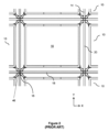
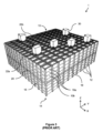
図1および図2に示されているように、「ビン」としても知られる、スタック可能なコンテナ10が、互いの上部にスタックされて、スタック12を形成する。スタック12は、たとえば、倉庫保管環境または製造環境において、グリッドフレームワーク構造14において配置される。グリッドフレームワーク構造14は、複数の保管列またはグリッド列からなる。グリッドフレームワーク構造における各グリッドが、コンテナのスタックを保管するための少なくとも1つのグリッド列を有する。図1は、グリッドフレームワーク構造14の概略斜視図であり、図2は、フレームワーク構造14内に配置されたビン10のスタック12を示す概略トップダウン図である。各ビン10が、一般に、複数の製品アイテム(図示せず)を保持する。ビン10内の製品アイテムは、適用例に応じて、同等のまたは異なる製品タイプであり得る。
As shown in Figures 1 and 2,
グリッドフレームワーク構造14は、水平部材18、20を支持する複数の直立部材16を備える。平行な水平グリッド部材18の第1のセットが、直立部材16によって支持された水平グリッド構造15を形成するように、平行な水平部材20の第2のセットに直角に、グリッドパターンにおいて配置される。部材16、18、20は、一般に金属から製造される。ビン10は、グリッドフレームワーク構造14が、ビン10のスタック12の水平移動に対してガードし、ビン10の垂直移動を誘導するように、グリッドフレームワーク構造14の部材16、18、20の間にスタックされる。
The
グリッドフレームワーク構造14の最上レベルは、スタック12の上部にわたってグリッドパターンにおいて配置されたレール22を含む、グリッドまたはグリッド構造15を備える。図3を参照すると、レールまたはトラック22は、複数の積荷取扱デバイス30を誘導する。平行なレール22の第1のセット22aが、グリッドフレームワーク構造14の上部にわたって、第1の方向(たとえば、X方向)においてロボット積荷取扱デバイス30の移動を誘導する。第1のセット22aに直角に配置された、平行なレール22の第2のセット22bが、第1の方向に直角な、第2の方向(たとえば、Y方向)において積荷取扱デバイス30の移動を誘導する。このようにして、レール22は、ロボット積荷取扱デバイス30が、水平X-Y平面における2つの次元において横方向に移動することを可能にする。積荷取扱デバイス30は、スタック12のいずれかの上の位置に移動され得る。
The top level of the
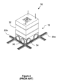
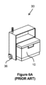
図4、図5、図6Aおよび図6Bに示されている、積荷取扱デバイス30の知られている形態が、参照により本明細書に組み込まれる、PCT特許公報第WO2015/019055号(Ocado)において説明され、各積荷取扱デバイス30が、グリッドフレームワーク構造14の単一のグリッド空間17をカバーする。この構成は、積荷ハンドラのより高い密度、したがって、所与のサイズの保管システムについてのより高いスループットを可能にする。
A known form of
例示的な積荷取扱デバイス30は車両32を備え、車両32は、フレーム構造14のレール22上で進むように配置される。車両32の前面におけるホイール34のペアと車両32の背面におけるホイール34のペアとからなる、ホイール34の第1のセットが、レール22の第1のセット22aの2つの隣接するレールと係合するように配置される。同様に、車両32の各側におけるホイール36のペアからなる、ホイール36の第2のセットが、レール22の第2のセット22bの2つの隣接するレールと係合するように配置される。積荷取扱デバイス30の移動中いつでも、ホイール34の第1のセットまたはホイール36の第2のセットのいずれかがレールのそれぞれのセット22a、22bと係合されるように、ホイール34、36の各セットが持ち上げられおよび降ろされ得る。たとえば、ホイール34の第1のセットがレールの第1のセット22aと係合され、ホイール36の第2のセットがレール22から離れて持ち上げられたとき、ホイール34の第1のセットは、X方向において積荷取扱デバイス30を移動させるように、車両32中に格納された駆動機構(図示せず)によって、駆動され得る。Y方向における移動を達成するために、ホイール34の第1のセットは、レール22から離れて持ち上げられ、ホイール36の第2のセットは降ろされて、レール22の第2のセット22bと係合する。駆動機構は、次いで、Y方向において積荷取扱デバイス30を移動させるようにホイール36の第2のセットを駆動するために使用され得る。
The exemplary
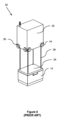
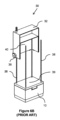
積荷取扱デバイス30は、上から保管コンテナを持ち上げるための持ち上げ機構、たとえば、クレーン機構を装備している。持ち上げ機構は、スプールまたはリール(図示せず)に巻かれたウインチテザーまたはケーブル38と、グリッパーデバイス39とを備える。図5に示されている持ち上げ機構は、垂直方向に延在する4つの持ち上げテザー38のセットを備える。テザー38は、保管コンテナ10への解放可能な接続のために、グリッパーデバイス39、たとえば、持ち上げフレームの、それぞれの4つのコーナーにおいてまたはその近くで接続される。たとえば、それぞれのテザー38が、持ち上げフレーム39の4つのコーナーの各々においてまたはその近くに配置される。グリッパーデバイス39は、保管コンテナ10の上部を解放可能に把持して、図1および図2に示されているタイプの保管システム1におけるコンテナのスタックからそれを持ち上げるように、構成される。たとえば、持ち上げフレーム39は、ビン10の上面を形成するリム中の対応するホール(図示せず)と嵌合するピン(図示せず)と、ビン10を把持するためにリムと係合可能である摺動クリップ(図示せず)とを含み得る。クリップは、持ち上げフレーム39内に格納され、ケーブル38自体または別個の制御ケーブル(図示せず)を通して運ばれる信号によって電力供給および制御される、好適な駆動機構によって、ビン10と係合するように駆動される。
The
スタック12の上部からビン10を除去するために、積荷取扱デバイス30は、最初に、スタック12の上にグリッパーデバイス39を位置決めするようにX方向およびY方向において移動される。グリッパーデバイス39は、次いで、図4および図6Bに示されているように、スタック12の上部のビン10と係合するようにZ方向において垂直方向に降ろされる。グリッパーデバイス39は、ビン10を把持し、次いで、ビン10が取り付けられた状態で、ケーブル38によって上方に引かれる。その垂直方向進行の上部において、ビン10は、車両本体32内に収容されたレール22の上に保持される。このようにして、積荷取扱デバイス30は、それとともにビン10を運んで、ビン10を別のロケーションに搬送するために、X-Y平面において異なる位置に移動され得る。ターゲットロケーション(たとえば、別のスタック12、保管システム中のアクセスポイント、またはコンベヤベルト)に到着すると、ビンまたはコンテナ10は、コンテナ受入部分から降ろされ、グラバーデバイス39から解放され得る。ケーブル38は、たとえば、フロアレベルを含む、スタック12の任意のレベルから、積荷取扱デバイス30がビンを取り出し、置くことを可能にするのに十分に長い。
To remove a
図3に示されているように、複数の同等の積荷取扱デバイス30が、各積荷取扱デバイス30が、システムのスループットを増加させるために同時に動作することができるように、提供される。図3に示されているシステムは、ビン10が、そこにおいてシステム中にまたはシステムの中から移され得る、ポートとして知られる、特定のロケーションを含み得る。追加のコンベヤシステム(図示せず)が、積荷取扱デバイス30によってポートに搬送されたビン10が、ピッキングステーション(図示せず)など、別のロケーションにそのコンベヤシステムによって移され得るように、各ポートに関連する。同様に、ビン10は、外部ロケーションからポートに、たとえば、ビン充填ステーション(図示せず)に、コンベヤシステムによって移動され、システム中のストックを補充するために、積荷取扱デバイス30によってスタック12に搬送され得る。
As shown in FIG. 3, multiple equivalent
各積荷取扱デバイス30は、一度に、1つのビン10を持ち上げ、移動させることができる。積荷取扱デバイス30は、それの下側部分に、コンテナ受入キャビティまたはリセス40を有する。リセス40は、図6Aおよび図6Bに示されているように、持ち上げ機構38、39によって持ち上げられたとき、コンテナ10を収容するようにサイズ決定される。リセス中にあるときに、コンテナ10は、車両32が、異なるグリッドロケーションに横方向に移動することができるように、下のレール22から離れて持ち上げられる。
Each
スタック12の上部にないビン10b(「ターゲットビン」)を取り出すことが必要である場合、上にあるビン10a(「非ターゲットビン」)は、ターゲットビン10bへのアクセスを可能にするために、最初に移動されなければならない。これは、以下、「掘り出し(digging)」と呼ばれる動作によって達成される。図3を参照すると、掘り出し動作中に、積荷取扱デバイス30のうちの1つが、ターゲットビン10bを含んでいるスタック12から各非ターゲットビン10aを連続的に持ち上げ、それを別のスタック12内の空いている位置に置く。ターゲットビン10bは、次いで、積荷取扱デバイス30によってアクセスされ、さらなる搬送のためのポートに移動され得る。
If it is necessary to remove a
各積荷取扱デバイス30は、中央コンピュータ、たとえば、マスタコントローラの制御下でリモートで動作可能である。また、システム中の各個々のビン10は、適切なビン10が、必要に応じて取り出され、搬送され、交換され得るように、追跡される。たとえば、掘り出し動作中に、各非ターゲットビンロケーションが、非ターゲットビン10aが追跡され得るように、ロギングされる。
Each
ワイヤレス通信およびネットワークが、マスタコントローラから、たとえば、1つまたは複数の基地局を介して、グリッド構造15上で動作可能な1つまたは複数の積荷取扱デバイス30に通信インフラストラクチャを提供するために使用され得る。マスタコントローラから命令を受信することに応答して、積荷取扱デバイス30中のコントローラが、積荷取扱デバイスの移動を制御するように様々な駆動機構を制御するように構成される。たとえば、積荷取扱デバイス30は、グリッド構造15上の特定のロケーションにおいてターゲット保管列からコンテナを取り出すように命令され得る。命令は、グリッド構造15のX-Y平面における様々な移動を含むことができる。前に説明されたように、ターゲット保管列に着くと、持ち上げ機構38、39は、保管コンテナ10を把持し、持ち上げるように動作され得る。コンテナ10が積荷取扱デバイス30のコンテナ受入空間40中に収容されると、コンテナ10は、その後、グリッド構造15上の別のロケーション、たとえば、「ドロップオフ(drop-off)ポート」に搬送される。ドロップオフポートにおいて、コンテナ10は、保管コンテナ中の任意のアイテムの取出しを可能にするために、好適なピックステーションに降ろされる。グリッド構造15上での積荷取扱デバイス30の移動は、積荷取扱デバイス30が、通常、グリッド構造15の周辺にある、充電ステーションに移動するように命令されることをも伴い得る。
Wireless communications and networks may be used to provide a communications infrastructure from the master controller, e.g., via one or more base stations, to one or more
グリッド構造15上で積荷取扱デバイス30を動かすために、積荷取扱デバイス30の各々が、ホイール34、36を駆動するためのモーターを装備している。ホイール34、36は、ホイールに接続された1つまたは複数のベルトを介して駆動されるか、またはホイールに組み込まれたモーターによって個々に駆動され得る。単一セル積荷取扱デバイスの場合(積荷取扱デバイス30のフットプリントが単一のグリッドセル17を占有する場合)、ホイールを駆動するためのモーターは、車両本体内の空間の限られた利用可能性により、ホイールに組み込まれ得る。たとえば、単一セル積荷取扱デバイス30のホイールは、それぞれのハブモーターによって駆動される。各ハブモーターが、内側固定子を形成するコイルを備えるホイールハブを中心として回転するように配置された複数の永久磁石をもつ外側回転子を備える。
To move the
図1~図6Bを参照しながら説明されたシステムは、多くの利点を有し、広範囲の保管および取出し動作に好適である。特に、それは、製品の極めて高密度の保管を可能にし、ビン10中に広範囲の異なるアイテムを保管する極めて経済的な方法を提供しながら、ピッキングのために必要とされるときにビン10のすべてへの適度に経済的なアクセスをも可能にする。
The system described with reference to Figures 1-6B has many advantages and is suitable for a wide range of storage and retrieval operations. In particular, it allows for very high density storage of products, providing a very economical way of storing a wide range of different items in the
しかしながら、本開示の目的は、保管システムにおいてリモートで動作される積荷取扱デバイスの正しいロケーションを確実に決定するための方法およびシステムを提供することである。 However, it is an object of the present disclosure to provide a method and system for reliably determining the correct location of a remotely operated load handling device in a storage system.
作業空間中で動作する1つまたは複数の搬送デバイスの移動の制御を支援する方法であって、本方法は、1つまたは複数の画像センサーによってキャプチャされた作業空間の画像表現を取得することと、インターフェースにおいて、作業空間の画像表現のターゲット画像部分を取得することと、ターゲット画像部分を作業空間中のターゲットロケーションにマッピングすることと、マッピングに基づいて、1つまたは複数の搬送デバイスが入るのを禁止されることになる、ターゲットロケーションを備える、作業空間中の除外ゾーン(exclusion zone)を決定することと、作業空間中の除外ゾーンを実装するために、除外ゾーンを表現する除外ゾーンデータを、制御システムに出力することとを備える、方法が提供される。 A method is provided for assisting in controlling the movement of one or more transport devices operating in a workspace, the method comprising: acquiring an image representation of the workspace captured by one or more image sensors; acquiring, at an interface, a target image portion of the image representation of the workspace; mapping the target image portion to a target location in the workspace; determining, based on the mapping, an exclusion zone in the workspace comprising the target location from which one or more transport devices will be prohibited; and outputting exclusion zone data representative of the exclusion zone to a control system for implementing the exclusion zone in the workspace.
さらに、本方法を実施するように構成されたプロセッサを備えるデータ処理装置が、提供される。また、コンピュータプログラムであって、上記プログラムがコンピュータによって実行されたとき、コンピュータに本方法を行わせる命令を備えるコンピュータプログラムが、提供される。同様に、コンピュータによって実行されたとき、コンピュータに本方法を行わせる命令を備える、コンピュータ可読記憶媒体が、提供される。 Furthermore, a data processing apparatus is provided that includes a processor configured to perform the method. Also provided is a computer program comprising instructions that, when executed by a computer, cause the computer to perform the method. Similarly, provided is a computer-readable storage medium comprising instructions that, when executed by a computer, cause the computer to perform the method.
さらに、作業空間中の搬送デバイス移動を制御するための制御システムを支援するためのシステムであって、支援システムが、作業空間の画像表現をキャプチャするための画像センサーと、作業空間の画像表現のターゲット画像部分を取得するためのインターフェースとを備え、ここにおいて、本システムは、ターゲット画像部分を作業空間中のターゲットロケーションにマッピングすることと、マッピングに基づいて、1つまたは複数の搬送デバイスが入るのを禁止される、ターゲットロケーションを備える、作業空間中の除外ゾーンを決定することと、作業空間中の除外ゾーンを実装するために、除外ゾーンを表現する除外ゾーンデータを、制御システムに出力することとを行うように構成された、システムが提供される。 Further provided is a system for assisting a control system for controlling transport device movement in a workspace, the assistance system comprising an image sensor for capturing an image representation of the workspace and an interface for acquiring target image portions of the image representation of the workspace, wherein the system is configured to: map the target image portions to target locations in the workspace; determine, based on the mapping, exclusion zones in the workspace comprising the target locations within which one or more transport devices are prohibited from entering; and output exclusion zone data representative of the exclusion zones to the control system for implementing the exclusion zones in the workspace.
さらに、上述の作業空間と、支援システムと、作業空間中の搬送デバイス移動を制御するための制御システムとを備える、保管システムであって、ここにおいて、作業空間が、X方向に延在する平行なトラックの第1のセットと、実質的に水平な平面において第1のセットに直交する、Y方向に延在する平行なトラックの第2のセットとによって形成された、グリッドを備え、グリッドが、複数のグリッド空間を備え、ここにおいて、1つまたは複数の搬送デバイスが、トラック上でX方向またはY方向のうちの少なくとも1つにおいて選択的に移動することと、単一のグリッド空間のフットプリント内でトラックの下にスタックされたコンテナを取り扱うこととを行うように配置される、保管システムが提供される。 There is further provided a storage system comprising the above-mentioned workspace, a support system, and a control system for controlling transport device movement in the workspace, wherein the workspace comprises a grid formed by a first set of parallel tracks extending in an X direction and a second set of parallel tracks extending in a Y direction, perpendicular to the first set in a substantially horizontal plane, the grid comprising a plurality of grid spaces, wherein one or more transport devices are arranged to selectively move on the tracks in at least one of the X direction or the Y direction and to handle containers stacked under the tracks within the footprint of a single grid space.
大まかに言えば、この説明は、1つまたは複数の搬送デバイスが動作する作業空間中での実装のための除外ゾーンを決定するためのシステムおよび方法を紹介する。除外ゾーンは、搬送デバイスのマスタコントローラによって実装され得、たとえば、作業空間中で動作する搬送デバイスが除外ゾーンに入るのを禁止するように機能する。除外ゾーンは、たとえば、倒れた、および/またはマスタコントローラとの通信を失った、欠陥のある搬送デバイスの周りで決定され得、したがって、欠陥のある搬送デバイスは、たとえば、後で、注意を払われ、たとえば作業空間から取り出され得る。これは、他の搬送デバイスが欠陥のある搬送デバイスと衝突するリスクを低下させながら、作業空間が使用可能なままであることを可能にする。 Broadly speaking, this description introduces a system and method for determining an exclusion zone for implementation in a workspace in which one or more transport devices operate. The exclusion zone may be implemented by a master controller of the transport devices and functions, for example, to prohibit transport devices operating in the workspace from entering the exclusion zone. The exclusion zone may be determined around a defective transport device, for example, that has fallen and/or lost communication with the master controller, so that the defective transport device, for example, may be subsequently attended to and, for example, removed from the workspace. This allows the workspace to remain usable while reducing the risk of other transport devices colliding with the defective transport device.
次に、同様の参照番号が同じまたは対応する部分を指定する、添付の図面を参照しながら、実施形態が単に例として説明される。 Embodiments will now be described, by way of example only, with reference to the accompanying drawings, in which like reference numbers designate the same or corresponding parts, and in which:
図1~図3に示されているタイプの保管システムでは、マスタコントローラから独立してグリッド構造15上で動作する所与の積荷取扱デバイス30の位置を決定することが有用である。各積荷取扱デバイス30が、グリッド構造上のあるロケーションから別のロケーションに所定の経路に沿って移動するように、マスタコントローラから制御信号を送られる。たとえば、所与の積荷取扱デバイス30が、グリッド構造15上の特定のロケーションに移動して、その特定のロケーションにおいてコンテナのスタックからターゲットコンテナを持ち上げるように、命令され得る。複数のそのようなデバイス30がグリッド構造15上でそれぞれの軌道に沿って移動する場合、たとえば、所与の積荷取扱デバイスとマスタコントローラとの間の通信が失われた場合に、グリッド構造15に対する所与の積荷取扱デバイス30の正確な位置を決定することが可能であることが有用である。たとえば、グリッド構造上でのまたはその周りでの、積荷取扱デバイスと別の物体、たとえば別の積荷取扱デバイスとの間の衝突が、その積荷取扱デバイス、または各積荷取扱デバイスが、マスタコントローラからの通信に無反応になることを、たとえば、それへの接続の喪失、および/またはグリッド構造15のトラック22からの係合解除によって、引き起こし得る。衝突は、たとえば、1つまたは複数の積荷取扱デバイスが、トラック22と不整合すること、またはグリッド構造上で倒れることを生じ得る。
In a storage system of the type shown in Figures 1-3, it is useful to determine the location of a given
グリッド構造15とその上で移動する積荷取扱デバイス30とをモニタすることが、複数の積荷取扱デバイスの動作を解決するために検出および/または作用されることになるような、積荷取扱デバイスの無反応のインスタンス(instance)を可能にすることができる。グリッド構造15に対する所与の積荷取扱デバイス30の位置の独立した評価を有することが、他の技術目的、たとえば、グリッド構造15上の積荷取扱デバイス30のあらかじめ決定された軌道をそれの真の位置に対してモニタすることのためにも、有用であり得る。
Monitoring the
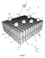
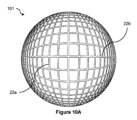
図7は、前に説明された、保管システムのグリッド構造(または単に「グリッド」)15を示す。グリッドは、X方向に延在する平行なトラックの第1のセット22aと、実質的に水平な平面において第1のセットに直交する、Y方向に延在する平行なトラックの第2のセット22bとによって形成される。グリッド15は、複数のグリッド空間17を有する。1つまたは複数の積荷取扱デバイス、または「搬送デバイス」30は、トラック22上でX方向またはY方向のうちの少なくとも1つにおいて選択的に移動することと、単一のグリッド空間17のフットプリント内でトラック22の下にスタックされたコンテナ10を取り扱うこととを行うように配置される。例では、1つまたは複数の搬送デバイス30は、1つのグリッド空間を占有する所与の搬送デバイスが、隣接するグリッド空間を占有するかまたは横断する別の搬送デバイスを妨害しないように、各々、同じく単一のグリッド空間のみを占有するフットプリントを有する。
7 shows the grid structure (or simply "grid") 15 of the storage system previously described. The grid is formed by a
グリッド15の上に、カメラ71が配設される。例では、カメラ71は、超広角カメラであり、すなわち、(「スーパー広角(super wide-angle)」レンズまたは「魚眼」レンズとも呼ばれる)超広角レンズを備える。カメラ71は、レンズ、たとえば、魚眼レンズを通して集束される入射光を受けるための画像センサーを含む。カメラ71は、グリッド15の少なくともセクションを含む視野72を有する。複数のカメラが、グリッド15全体を観測するために使用され得、たとえば、各カメラ71が、グリッド15のセクションをカバーするそれぞれの視野72を有する。超広角レンズは、他のレンズタイプと比較して、たとえば、180度立体角までの、その比較的大きい視野72のために選択され得、これは、グリッド15をカバーするためにより少数のカメラが必要とされることを意味する。また、空間は、グリッド15の上部と、周囲構造、たとえば倉庫屋根との間で限られており、したがって、グリッド15の上のカメラ71の高さを制約し得る。超広レンズカメラが、他のカメラタイプと比較してグリッド15の上の比較的低い高さにおいて比較的大きい視野を提供することができる。
Above the
1つまたは複数のカメラ71は、搬送デバイス30の作業空間をモニタするために使用され得、作業空間は、グリッド構造15を含む。たとえば、1つまたは複数のカメラ71からの画像供給が、欠陥のある、たとえば、無反応な、搬送デバイスのインスタンスを監視するために、グリッド15からリモートにある1つまたは複数のコンピュータモニタ上に表示され得る。したがって、オペレータは、そのようなインスタンスを検出し、たとえば、搬送デバイスとマスタコントローラとの間の通信リンクをリセットすること、または機械的問題に対する手動介入を要求することによって、問題点を解決するように作用し得る。
One or
作業空間のための効果的なモニタリングまたは監視システムは、作業空間の上に位置する1つまたは複数の超広角カメラの較正を組み込む。超広角カメラの正確な較正は、超広角レンズによってひずんだ、超広角カメラによりキャプチャされた画像との対話が、作業空間に正しくマッピングされることを可能にする。したがって、オペレータは、ひずんだ画像中のピクセルのエリアを選択することができ、これは、たとえば、作業空間中のグリッド空間の対応するエリアにマッピングされる。他のシナリオでは、カメラ71からのひずんだ画像は、作業空間中の欠陥のある搬送デバイス30を検出し、作業空間中のそれのロケーションと、さらには、一意のIDラベルなど、検出された搬送デバイス30の識別情報とを出力するために、処理され得る。そのような例は、以下の実施形態において説明される。
An effective monitoring or surveillance system for a workspace incorporates the calibration of one or more ultra-wide-angle cameras located above the workspace. Accurate calibration of the ultra-wide-angle camera allows interactions with the image captured by the ultra-wide-angle camera, distorted by the ultra-wide-angle lens, to be correctly mapped to the workspace. Thus, an operator can select an area of pixels in the distorted image, which is mapped to a corresponding area of grid space in the workspace, for example. In other scenarios, the distorted image from the
較正プロセス
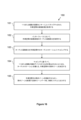
較正プロセス130は、図13に示されている例に従って、超広角カメラ71によってキャプチャされた、グリッド15のセクション、すなわちグリッドセクションの画像を取得すること131を含む。画像を取得することは、たとえば、プロセッサにおいて、画像を表現する画像データを取得すること、たとえば、受信することを含む。たとえば、画像データは、インターフェース、たとえば、カメラシリアルインターフェース(CSI)を介して、受信され得る。画像信号プロセッサ(ISP)が、画像データを表示のために準備するために、画像データの初期処理、たとえば、飽和補正、再正規化、ホワイトバランス調整および/またはデモザイキングを実施し得る。
Calibration Process The
超広角カメラ71に対応する複数のパラメータの初期値も取得される132。それらのパラメータは、超広角カメラの焦点距離と、グリッドセクションの上の超広角カメラの位置を表現する並進ベクトルと、超広角カメラの傾きおよび回転を表現する回転ベクトルとを含む。これらのパラメータは、カメラ71の超広角レンズによってひずんだ画像中のピクセルを、保管システムの直交グリッド15に対して配向された平面にマッピングするための、マッピングアルゴリズムにおいて使用可能である。マッピングアルゴリズムは、以下でより詳細に説明される。
Initial values for a number of parameters corresponding to the
較正プロセス130は、画像を、超広角カメラによってキャプチャされたグリッドセクションの画像中のトラックを検出/予測するようにトレーニングされたニューラルネットワークを使用して、処理すること133を含む。
The
ニューラルネットワーク
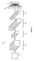
図9は、ニューラルネットワークアーキテクチャの一例を示す。例示的なニューラルネットワーク90は、畳み込みニューラルネットワーク(CNN)である。CNNの一例は、フライブルク大学のコンピュータサイエンス学部によって開発されたU-Netアーキテクチャであるが、他のCNN、たとえば、VGG-16 CNNが使用可能である。CNN90への入力91が、この例では画像データを備える。入力画像データ91は、所与の数のピクセル幅および所与の数のピクセル高さであり、1つまたは複数の色チャネル(たとえば、赤色、緑色および青色チャネル)を含む。
Neural Network Figure 9 shows an example of a neural network architecture. The exemplary
CNN90の畳み込み層92、94が、一般に、特徴マップを作成するために、入力データ91から特定の特徴を抽出し、画像の小さい部分に対して動作し得る。全結合層96は、出力97、たとえば、入力画像91中に存在することが予測される物体のクラスを指定する分類データを決定するために、特徴マップを使用する。
The convolutional layers 92, 94 of the
図9の例では、第1の畳み込み層92の出力は、第2の畳み込み層94に入力される前に、プーリング層93においてプーリングを受ける。プーリングは、たとえば、画像または特徴マップの領域のための値が、たとえば領域内の最も高い値をとることによって、アグリゲートされるかまたは組み合わせられることを可能にする。たとえば、2×2の最大プーリングでは、出力全体を移すのではなく、第1の畳み込み層92から出力された特徴マップの2×2ピクセルパッチ内の第1の畳み込み層92の出力の最も高い値が、第2の畳み込み層94への入力として使用される。したがって、プーリングは、ニューラルネットワーク90の後続の層のための算出量を低減することができる。プーリングの効果は、関係する層におけるフレームのサイズの低減として、図9に概略的に示されている。さらなるプーリングが、第2のプーリング層95において、第2の畳み込み層94と全結合層96との間で実施される。図9中のニューラルネットワーク90の概略表現が、説明しやすいように大幅に簡略化されており、一般的なニューラルネットワークは、著しくより複雑であり得ることを諒解されたい。
In the example of FIG. 9, the output of the first
概して、図9のニューラルネットワーク90などのニューラルネットワークは、そのニューラルネットワークが特定の目的のためにトレーニングされる、「トレーニングフェーズ」と呼ばれるものを受け得る。ニューラルネットワークは、一般に、グラフの(ニューロンに対応する)頂点または(結合に対応する)エッジが、それぞれ、重みに関連する、有向の、重み付けされたグラフを形成する相互結合された人工ニューロンの層を含む。重みは、トレーニング全体にわたって調整され得、個々のニューロンの、および、したがって、全体としてニューラルネットワークの出力を変更する。CNNでは、全結合層96は、一般に、1つの層中のあらゆるニューロンを別の層中のあらゆるニューロンに結合し、したがって、画像が、特定のクラスの物体、または特定のクラスに属する特定のインスタンスを含むかどうかなど、画像の全体的特性を識別するために使用され得る。
In general, a neural network, such as the
本コンテキストでは、ニューラルネットワーク90は、たとえば、所定のクラスの物体のうちのある物体が画像中に存在するかどうかを決定するために、画像データを処理することによって物体識別を実施するようにトレーニングされる(とはいえ、他の例では、代わりに、ニューラルネットワーク90が画像の他の画像特性を識別するようにトレーニングされていることがある)。たとえば、このようにしてニューラルネットワーク90をトレーニングすることは、画像データに適用されるべき重みを表現する重みデータを生成する(たとえば、異なる重みが、多層ニューラルネットワークアーキテクチャの異なるそれぞれの層に関連する)。これらの重みの各々が、たとえば、重みのカーネルを画像パッチと畳み込むために、画像パッチの対応するピクセル値を乗算される。
In the present context, the
超広角カメラ較正のコンテキストに特有なことには、ニューラルネットワーク90は、グリッドセクションの所与の画像中のグリッド15のトラック22を検出するために、超広角カメラによってキャプチャされたグリッドセクションの入力画像のトレーニングセットを用いてトレーニングされる。例では、トレーニングセットは、入力画像に対応する、抽出されたトラック特徴のみを示す、マスク画像を含む。たとえば、マスク画像は、手動で作り出される。したがって、マスク画像は、画像のトレーニングセットを使用することでトレーニングすべきニューラルネットワーク90についての所望の結果として働くことができる。トレーニングされると、ニューラルネットワーク90は、超広角カメラによってキャプチャされたグリッド構造15の少なくとも一部の画像中のトラック22を検出するために使用され得る。
Specific to the context of ultra-wide camera calibration, the
較正プロセス130は、超広角カメラ71によってキャプチャされたグリッドセクションの画像を、画像中のトラック22を検出するために、トレーニングされたニューラルネットワーク90を用いて、処理すること133を含む。少なくとも1つのプロセッサ(たとえば、ニューラルネットワークアクセラレータ)が、処理133を行うために使用され得る。画像処理133は、グリッドセクションの画像中にキャプチャされた、トラック、特に、平行なトラックの第1のセットおよび第2のセットのモデルを生成する。たとえば、モデルは、ニューラルネットワーク90によって決定された、グリッドセクションのひずんだ画像中のトラックの予測の表現を備える。トラックのモデルは、例ではマスクまたは確率マップに対応する。
The
次いで、決定されたトラックモデル中の選択されたピクセルが、超広角カメラに対応する複数のパラメータを組み込むマッピング、たとえば、マッピングアルゴリズムを使用して、グリッド15上の対応するポイントにマッピングされる134。取得された初期値は、マッピングアルゴリズムへの入力として使用される。
Selected pixels in the determined track model are then mapped 134 to corresponding points on the
誤差関数(または「損失関数」)が、マッピングされたグリッド座標と、選択されたピクセルに対応するポイントの「真の」、たとえば知られている、グリッド座標との間の不一致に基づいて、決定される135。たとえば、X方向トラック22aの中心にある選択されたピクセルが、Y方向における半整数値をもつグリッド座標、たとえば(x,y.5)に対応するべきであり、ここで、xは知られていない数であり、yは知られていない整数である。同様に、Y方向トラック22bの中心にある選択されたピクセルが、X方向における半整数値をもつグリッド座標、たとえば(x’.5,y’)に対応するべきであり、ここで、x’は知られていない整数であり、y’は知られていない数である。例では、グリッドセルの幅および長さ(またはその比)が、たとえば、キーポイントについてセルx,y座標を計算し、それらがトラック上にある(たとえば、n.5の座標値、ここで、nは整数である)かどうかを確認するために、損失関数において使用される。
An error function (or "loss function") is determined 135 based on the discrepancy between the mapped grid coordinates and the "true", e.g., known, grid coordinates of the points corresponding to the selected pixels. For example, the selected pixel at the center of the
超広角カメラに対応する複数のパラメータの初期値は、次いで、決定された誤差関数に基づいて、更新された値に更新される136。たとえば、ブロイデン-フレッチャー-ゴールドファーブ-シャンノ(BFGS)アルゴリズムが、誤差関数と初期パラメータ値とを入力として使用して適用される。例では、複数のパラメータの更新された値は、反復的に決定され、誤差関数が各更新とともに再計算される。反復は、誤差関数が、たとえば、連続反復間で、または初期誤差関数と比較して、所定のしきい値未満だけ低減されるまで、あるいは誤差関数の絶対値が所定のしきい値を下回るまで、続き得る。他の反復アルゴリズム、たとえば、逐次2次計画法(SQP:sequential quadratic programming)または逐次最小2乗2次計画法(SLSQP:sequential least-squares quadratic programming)が、複数のパラメータについての近似解を改善するシーケンスを生成するために、初期値とともに使用され得、シーケンスにおける所与の近似が、前のものから導出される。場合によっては、反復アルゴリズムは、複数のパラメータの値を最適化するために使用される。たとえば、更新された値は、複数のパラメータの最適化された値である。
The initial values of the parameters corresponding to the ultra-wide camera are then updated to updated values based on the
超広角カメラに対応する複数のパラメータの初期値を更新すること136は、複数のパラメータについて1つまたは複数のそれぞれの境界値を適用することを伴う。たとえば、回転ベクトルに関連する回転角についての境界値は、実質的に0度および実質的に+5度である。追加または代替として、並進ベクトルの平面成分についての境界値は、グリッドセルの長さの±0.6である。追加または代替として、並進ベクトルの高さ成分についての境界値は、グリッドの1800mmおよび2100mm、または1950mmおよび2550mm、または2000mmおよび2550mm上である。たとえば、カメラ高さについての下限が、1800~2000mmの範囲内である。たとえば、カメラ高さについての上限が、2100~2600mmの範囲内である。追加または代替として、カメラの焦点距離についての境界値は、0.23および0.26cmである。複数のパラメータについて1つまたは複数のそれぞれの境界値を適用することは、更新、たとえば最適化、プロセスが、実現可能な領域または解空間、すなわち、1つまたは複数の境界条件を満たすすべての可能な値のセットにおいて、実施されることを意味することができる。 Updating 136 the initial values of the plurality of parameters corresponding to the ultra-wide-angle camera involves applying one or more respective bounds for the plurality of parameters. For example, the bounds for the rotation angle associated with the rotation vector are substantially 0 degrees and substantially +5 degrees. Additionally or alternatively, the bounds for the planar component of the translation vector are ±0.6 of the length of the grid cell. Additionally or alternatively, the bounds for the height component of the translation vector are 1800 mm and 2100 mm, or 1950 mm and 2550 mm, or 2000 mm and 2550 mm above the grid. For example, the lower bound for the camera height is in the range of 1800-2000 mm. For example, the upper bound for the camera height is in the range of 2100-2600 mm. Additionally or alternatively, the bounds for the focal length of the camera are 0.23 and 0.26 cm. Applying one or more respective boundary values for multiple parameters can mean that the updating, e.g., optimization, process is carried out in a feasible region or solution space, i.e., the set of all possible values that satisfy one or more boundary conditions.
複数のパラメータの更新された値は、マッピングアルゴリズムを介した、超広角カメラ71によってキャプチャされたグリッドセクション画像中のピクセルの、グリッド15上の対応するポイントへの将来のマッピングのために、電子的に記憶される137。たとえば、複数のパラメータの記憶された値は、データストレージから取り出され、超広角カメラ71によってキャプチャされたグリッドセクションの所与の画像中の所与のピクセルに対応するグリッド座標を算出するために、マッピングアルゴリズムにおいて使用される。例では、更新された値は、超広角カメラ71に関連する保管ロケーション(storage location)において、たとえば、データベース中に、記憶される。たとえば、ルックアップ機能またはテーブルが、グリッド15の上で保管システム1において採用された任意の所与の超広角カメラに関連する記憶されたパラメータ値を見つけるためにデータベースとともに使用され得る。
The updated values of the parameters are electronically stored 137 for future mapping of pixels in the grid section image captured by the
グリッド15の上に配設された所与のカメラ71の較正に続いて、カメラ71によってキャプチャされたグリッドセクションの画像(たとえば、「スナップショット」)が、オペレータによる対話のために、平坦化され、すなわち、ひずんでいないようにされ得る。たとえば、説明される画像からグリッドへのマッピング(image-to-grid mapping)機能を使用して、グリッドセクションのひずんだ画像81は、図11の例に示されているように、グリッドセクションの平坦化された画像111にコンバートされ得る。平坦化は、ひずんだ画像81中で平坦化すべきグリッドセルのエリアを選択することと、それらのセルに対応するグリッド座標をマッピング機能に入力することとを伴い、マッピング機能は、ひずんだ画像81からのどのそれぞれのピクセル値が、それぞれのグリッド座標についての平坦化された画像111にコピーされるべきであるかを決定する。たとえば、グリッドセルごとのピクセルの、ターゲット解像度が、平坦化された画像111について設定され得、ターゲット解像度は、グリッドセル寸法の比に対応する比を有し得る。(ターゲット解像度とグリッドセルの選択された数とに従う)平坦化された画像中で必要とされるすべてのピクセル値が決定されると、平坦化された画像111が生成され得る。
Following calibration of a given
スナップショットは、所定の間隔において、たとえば10秒ごとに、カメラ71によってキャプチャされ、対応する平坦化された画像111にコンバートされ得る。直近の平坦化された画像111は、たとえば、カメラ71によってカバーされたグリッドセクションを閲覧することを望むオペレータによって、ディスプレイ上で閲覧するためにストレージに記憶される。オペレータは、代わりに、グリッドショットのスナップショットを撮り直し、それを平坦化させることを選定し得る。したがって、オペレータは、平坦化された画像111中の領域、たとえば、ピクセルを選択し、本明細書で説明される、画像からグリッドへのマッピング機能に基づいて、それらの選択された領域をグリッド座標にコンバートさせることができる。いくつかの場合には、平坦化された画像111は、平坦化された画像111中で閲覧可能なグリッド空間についてのグリッド座標のアノテーション(annotation)を含む。各カメラ71に対応する平坦化された画像111は、ひずんだ画像81、82と比較して、グリッド15をモニタするためによりユーザフレンドリであり得る。
Snapshots may be captured by the
グリッドから画像へのマッピング(grid to image mapping)
グリッド15上の現実世界のポイントを、カメラによってキャプチャされた画像中のピクセルにマッピングすることが、算出アルゴリズムによって行われる。グリッドポイントは、最初に、超広角カメラ71に対応する平面上に投影される。たとえば、回転行列を使用する回転と、X方向およびY方向における平面並進とのうちの少なくとも1つが、グリッドフレームワーク構造14中のx、y、およびz座標を有するポイントに適用される。超広角カメラの焦点距離fは、グリッド15に対する3次元座標をもつポイントを、超広角カメラ71に対する2次元平面上に投影するために使用され得る。たとえば、超広角カメラ71の平面におけるマッピングされたポイントqの座標は、q=f・p[x,y]÷pzとして計算され、ここで、p[x,y]およびpzは、それぞれ、グリッド15に対するポイントpの平面x-y座標および第3のz座標である。
Grid to image mapping
A computational algorithm maps real-world points on the
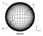
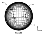
超広角カメラ平面上に投影されたポイントqは、ポイントの第1のデカルト座標を決定するために、その平面におけるデカルト座標系と整合され得る。たとえば、ポイントをデカルト座標系と整合させることは、ポイント、または平面におけるポイントの位置ベクトル(たとえば、原点からポイントへのベクトル)を回転させることを伴う。したがって、回転は、たとえば、カメラによってキャプチャされた画像中の典型的なグリッド配向と整合するためのものであるが、グリッドのX方向およびY方向が、キャプチャされた画像とすでに整合されている場合、必要でないことがある。回転は、例では実質的に90度である。図8Aおよび図8Bに示されているように、グリッドのX方向およびY方向は、画像の水平軸および垂直軸に関して90度だけオフセットされ、したがって、回転は、グリッドのX方向およびY方向が、キャプチャされた画像の水平軸および垂直軸と整合するように、このオフセットを「補正」する。 A point q projected onto the ultra-wide camera plane may be aligned with a Cartesian coordinate system in that plane to determine a first Cartesian coordinate of the point. For example, aligning a point with a Cartesian coordinate system involves rotating the point, or the point's position vector in the plane (e.g., a vector from the origin to the point). Thus, the rotation is, for example, to align with a typical grid orientation in an image captured by the camera, but may not be necessary if the X and Y directions of the grid are already aligned with the captured image. The rotation is substantially 90 degrees in the example. As shown in Figures 8A and 8B, the X and Y directions of the grid are offset by 90 degrees with respect to the horizontal and vertical axes of the image, and thus the rotation "corrects" for this offset so that the X and Y directions of the grid are aligned with the horizontal and vertical axes of the captured image.
グリッドから画像へのマッピング(grid-to-image mapping)アルゴリズムは、標準的三角法を使用して、第1のデカルト座標を第1の極座標にコンバートすることを続ける。次いで、ひずみモデルが、第2の、たとえば「ひずんだ」極座標を生成するために、ポイントの第1の極座標に適用される。例では、ひずみモデルは、r’=f・arctan(r/f)によって与えられるひずみのタンジェントモデルを備え、ここで、rおよびr’は、それぞれ、ポイントのひずんでいない半径方向座標およびひずんだ半径方向座標であり、fは超広角カメラの焦点距離である。 The grid-to-image mapping algorithm continues by converting the first Cartesian coordinates to first polar coordinates using standard trigonometry. A distortion model is then applied to the first polar coordinates of the point to generate second, e.g., "distorted", polar coordinates. In an example, the distortion model comprises a tangent model of distortion given by r' = f arctan(r/f), where r and r' are the undistorted and distorted radial coordinates of the point, respectively, and f is the focal length of the ultra-wide-angle camera.
第2の極座標は、次いで、同じ標準的三角法を逆に使用して、(第2の)デカルト座標に逆にコンバートされる。次いで、第2のデカルト座標に基づいて、画像中のピクセルの画像座標が決定される。例では、この決定は、第2のデカルト座標をセンタリング解除する(de-center)ことまたは再スケーリングすることのうちの少なくとも1つを含む。追加または代替として、第2のデカルト座標の縦座標(y座標)は反転され、たとえばx軸においてミラーリングされる。 The second polar coordinates are then converted back to (second) Cartesian coordinates using the same standard trigonometric techniques inversely. Image coordinates of pixels in the image are then determined based on the second Cartesian coordinates. In an example, this determination includes at least one of de-centering or rescaling the second Cartesian coordinates. Additionally or alternatively, the ordinate (y-coordinate) of the second Cartesian coordinates is inverted, e.g., mirrored in the x-axis.
画像からグリッドへのマッピング
カメラ71によってキャプチャされた画像中のピクセルをグリッド15上の現実世界のポイントにマッピングすることが、異なる算出アルゴリズムによって行われる。たとえば、画像からグリッドへのマッピングアルゴリズムは、上記で説明されたグリッドから画像へのマッピングアルゴリズムの逆であり、各数学演算が反転される。
Image to Grid Mapping Mapping pixels in the image captured by the
画像中の所与のピクセルについて、画像中のピクセルの画像座標に基づいて、マッピングされたポイントの(第2の)デカルト座標が決定される。たとえば、この決定は、たとえば、画像座標をセンタリングすることまたは正規化することのうちの少なくとも1つを含む、画像中のピクセルを初期化することを伴う。前述のように、縦座標は、いくつかの例では反転される。第2のデカルト座標は、前述の標準的三角法を使用して第2の極座標にコンバートされる。ラベル「第2の」の使用は、説明されるグリッドから画像へのアルゴリズムにおいて行われるコンバージョンとの一貫性のために使用されるが、任意である。 For a given pixel in the image, the (second) Cartesian coordinate of the mapped point is determined based on the image coordinate of the pixel in the image. For example, this determination involves initializing the pixel in the image, including, for example, at least one of centering or normalizing the image coordinate. As mentioned above, the ordinate is inverted in some examples. The second Cartesian coordinate is converted to a second polar coordinate using standard trigonometry as described above. The use of the label "second" is used for consistency with the conversion performed in the grid-to-image algorithm described, but is arbitrary.
逆ひずみモデルが、第1の、たとえば「ひずんでいない」、極座標を生成するために第2の極座標に適用される。例では、逆ひずみモデルは、r=f・tan(r’/f)によって与えられるひずみのタンジェントモデルに基づき、ここで、この場合も、r’はポイントのひずんだ半径方向座標であり、rはポイントのひずんでいない半径方向座標であり、fは超広角カメラの焦点距離である。したがって、例では、画像からグリッドへのマッピングにおいて使用される逆ひずみモデルは、グリッドから画像へのマッピングにおいて使用されるひずみモデルの逆関数、または「反関数(anti-function)」である。 An inverse distortion model is applied to the second polar coordinates to generate first, e.g., "undistorted", polar coordinates. In the example, the inverse distortion model is based on a tangent model of distortion given by r = f tan(r'/f), where again r' is the distorted radial coordinate of the point, r is the undistorted radial coordinate of the point, and f is the focal length of the ultra-wide camera. Thus, in the example, the inverse distortion model used in the image-to-grid mapping is the inverse function, or "anti-function," of the distortion model used in the grid-to-image mapping.
画像からグリッドへのマッピングアルゴリズムは、第1の極座標を第1のデカルト座標にコンバートすることを続ける。第1のデカルト座標は、超広角カメラに対応する平面におけるデカルト座標系と、整合解除、または非整合され得る。たとえば、ポイントをデカルト座標系と整合解除させることは、ポイント、または平面におけるポイントの位置ベクトル(たとえば、原点からポイントへのベクトル)に回転変換を適用することを伴う。回転は、例では実質的に90度である。したがって、この回転は、グリッドから画像へのマッピングにおいて前に説明された、グリッドのX方向およびY方向と、キャプチャされた画像の水平軸および垂直軸との間のオフセットへの何らかの「補正」を「元に戻し」得る。 The image-to-grid mapping algorithm continues by converting the first polar coordinate to a first Cartesian coordinate. The first Cartesian coordinate may be disaligned or misaligned with a Cartesian coordinate system in the plane corresponding to the ultra-wide camera. For example, disaligning the point with the Cartesian coordinate system involves applying a rotation transformation to the point, or to the point's position vector in the plane (e.g., the vector from the origin to the point). The rotation is substantially 90 degrees in the example. This rotation may therefore "undo" any "correction" to the offset between the X and Y directions of the grid and the horizontal and vertical axes of the captured image, as previously described in the grid-to-image mapping.
最終的に、ポイントは、グリッドに対するポイントのグリッド座標を決定するために、カメラ71に対応する(第2の)平面から、グリッド15に対応する(第1の)平面上に投影される。
Finally, the point is projected from the (second) plane corresponding to the
例では、グリッド15に対応する平面上にポイントを投影することは、p=B-1・(f・t-q・z)を算出することを伴い、ここで、B=q・R3,[1,2]-f・R[1,2],[1,2]である。これらの方程式では、pはグリッド平面におけるポイント座標を備え、qはカメラ平面におけるデカルト座標を備え、fは、前述のように超広角カメラの焦点距離である。さらに、tは平面並進ベクトルであり、zは、超広角カメラとグリッドとの間の距離(たとえば高さ)であり、Rは、回転ベクトルに関係する3次元回転行列である。回転ベクトルは、回転の回転軸を表現する方向と回転の角度を表現する大きさとを備える。角度-軸回転ベクトルに対応する回転行列Rは、たとえば、ロドリゲスの回転公式を使用して、ベクトルから決定され得る。
In an example, projecting a point onto a plane corresponding to the
次に、カメラ平面からのひずんでいない2Dポイントqを投影するための機能の数学的導出が、完全のために提供される。上からの、グリッドから画像への投影から始めると、q=f・p’[x,y]÷p’zであり、ここで、p’は、回転および並進されたグリッドポイントpであり、すなわち、p’=R・p+(tx,ty,z)Tであり、qからpを導出することを目的としている。p’について整理し、代入を行うと、以下のようになる。 Next, a mathematical derivation of the function for projecting an undistorted 2D point q from the camera plane is provided for completeness. Starting with the projection from the grid onto the image from above, q = f p' [x,y] / p' z , where p' is the rotated and translated grid point p, i.e., p' = R p + (t x , ty , z ) T , and the goal is to derive p from q. Rearranging and substituting for p' gives:
![]()
![]()
![]()
![]()
![]()
![]()
![]()
![]()
![]()
![]()
カメラからのグリッド上のポイントpの所望の距離が高さパラメータzによって与えられるので、ポイントの並進において、pz=0であると仮定され得る。したがって、すべてのpz項が除去されて、以下のようになり得る。 Since the desired distance of a point p on the grid from the camera is given by the height parameter z, in translating the point, it can be assumed that p z =0. Therefore, all p z terms can be eliminated, leaving:
![]()
![]()
![]()
![]()
行列B=(q・R3,[1,2]-f・R)を定義することによって、式は、B・p[x,y]=f・t-z・qにさらに簡略化され得、これは、逆行列B-1を使用することによって、ポイントpを算出するための上記の方程式として帰着する。 By defining the matrix B = (q·R 3,[1,2] - f·R), the formula can be further simplified to B·p [x,y] = f·t - z·q, which reduces to the above equation for calculating point p by using the inverse matrix B −1 .
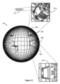
較正プロセス130に戻ると、いくつかの場合には、グリッド15に関して位置決めされた、グリッドセルマーカーに符号化されたグリッドセル座標データが、キャプチャされた画像中のピクセルに対応する算出されたグリッド座標を較正するために使用され得る。たとえば、グリッドセルマーカーは、たとえば所定のグリッドセル17中に置かれた、サインボードであり、対応するセル座標データが各サインボード上にマークされる。プロセス130は、たとえば、キャプチャされた画像を、画像中のグリッドセルマーカーを検出するために、処理することと、次いで、マッピングされたグリッド座標を較正する際に使用するために、グリッドセルマーカーに符号化されたグリッドセル座標データを抽出することとを含む。各グリッドセルマーカーは、それぞれのグリッドセル中にあり、たとえば、それぞれのカメラ71の下に、それの視野72内にある。
Returning to the
画像処理は、グリッドセクションの画像中のグリッドセルマーカーのインスタンスを検出するようにトレーニングされた、物体検出モデル、たとえばニューラルネットワークを使用することを伴い得る。コンピュータビジョンプラットフォーム、たとえば、Google(登録商標)によるCloud Vision API(アプリケーションプログラミングインターフェース)が、物体検出モデルを実装するために使用され得る。物体検出モデルは、グリッドセルマーカーを含むグリッドセクションの画像を用いてトレーニングされ得る。物体検出モデルが、ニューラルネットワーク、たとえばCNNを含む、例では、図9を参照する説明が、それに応じて適用される。 The image processing may involve using an object detection model, e.g., a neural network, trained to detect instances of grid cell markers in images of the grid section. A computer vision platform, e.g., Cloud Vision API (Application Programming Interface) by Google®, may be used to implement the object detection model. The object detection model may be trained with images of the grid section including the grid cell markers. In examples where the object detection model includes a neural network, e.g., CNN, the description with reference to FIG. 9 applies accordingly.
キャプチャされた画像中で表現されたグリッドセクション上のポイントへの画像中のピクセルのマッピングによって生成された、グリッド座標は、抽出されたセル座標データに基づいてグリッド全体に較正され得る。たとえば、所与のピクセルに対応するマッピングされたグリッドポイントは、グリッドセルの単位の座標、たとえば、X方向におけるグリッドセルの数xとY方向におけるグリッドセルの数yとをもつ(x,y)を備える。しかしながら、カメラ71によってキャプチャされたグリッドセルは、グリッドセクション、すなわちグリッド15のセクションのものであり、したがって、必ずしもグリッド15全体であるとは限らない。したがって、画像中にキャプチャされたグリッドセクションに対するマッピングされたグリッド座標(x,y)は、グリッド全体に関するグリッドセクションの相対ロケーションに基づいて、グリッド全体に対するグリッド座標(x’,y’)に較正され得る。グリッド全体に対するグリッドセクションのロケーションは、説明されるように、画像中にキャプチャされたグリッドセルマーカーに符号化されたグリッドセル座標データを抽出することによって決定され得る。
Grid coordinates generated by mapping pixels in an image to points on a grid section represented in a captured image may be calibrated to the entire grid based on the extracted cell coordinate data. For example, a mapped grid point corresponding to a given pixel has coordinates in units of grid cells, e.g. (x,y) with x being the number of grid cells in the X direction and y being the number of grid cells in the Y direction. However, the grid cells captured by
図10Aは、超広角カメラ71によってキャプチャされた、グリッドセクションの画像81を、画像中のトラック22を検出するために、トレーニングされたニューラルネットワーク90を用いて、処理することによって生成された、トラックの例示的なモデル101を示す。モデル101は、ニューラルネットワーク90によって決定された、グリッドセクションのひずんだ画像中のトラック22a、22bの予測の表現を備える。トラックモデル101からグリッド15上の対応するポイントにピクセルをマッピングすることが、説明されるようにカメラ71を較正するために行われ得る。たとえば、較正は、キャプチャされた画像81、82中のピクセルとグリッド15上のポイントとの間のマッピングのために使用される、カメラ71に関連する複数のパラメータを更新すること、たとえば最適化することを伴う。
10A illustrates an
例では、グリッドセクションのモデル101は、平行なトラックの第1のセット22aおよび第2のセット22bの中心線のみを表現するように改良され得る。したがって、トラックモデル101からグリッド15上の対応するポイントにマッピングされるべきピクセルは、たとえば、生成されたモデル101中の平行なトラックの第1のセット22aおよび第2のセット22bの中心線上にあるピクセルである。改良することは、たとえば、水平線および垂直線検出カーネルでモデルをフィルタ処理することを伴う。それらのカーネルは、たとえば、他のカーネルが、エッジ検出におけるエッジなど、画像の他の特徴を識別するために使用され得るのと同じようにして、トラックの中心線がモデル101中で識別されることを可能にする。各カーネルは、所与のサイズ、たとえば3×3行列であり、これは、所与のストライドでモデル101中の画像データと畳み込まれ得る。たとえば、水平線検出カーネルは、行列
In an example, the

として表現可能である。 It can be expressed as:
同様に、垂直線検出カーネルは、たとえば、行列 Similarly, a vertical line detection kernel can be written as, for example, the matrix

として表現可能である。 It can be expressed as:
例では、フィルタ処理することは、水平線および垂直線検出カーネルを使用してモデル101のピクセル値を収縮させる(erode)ことと膨張させる(dilate)こととのうちの少なくとも1つを伴う。たとえば、収縮(erosion)機能と膨張(dilation)機能とのうちの少なくとも1つが、カーネルを使用してモデル101に適用される。収縮機能は、カーネルをモデルと畳み込むことによって、前景物体、この場合、生成されたモデル101中のトラック22a、22bの境界を効果的に「収縮させる」。収縮中に、カーネルの下で畳み込まれるすべてのピクセルが「1」に等しい場合のみ、元のモデル中のピクセル値(「1」または「0」のいずれか)は、「1」の値に更新され、他の場合、それは収縮させられる(「0」の値に更新される)。事実上、モデル101中のトラック22a、22bの境界の近くのすべてのピクセルが、トラック22a、22bの各々の厚さが実質的にその中心線まで減少するように、収縮において使用されるカーネルのサイズに応じて、破棄されることになる。膨張機能は、収縮機能の反対であり、収縮の後に残る中心線を効果的に「膨張させる」または広げるために、収縮の後に適用され得る。この膨張は、改良されたモデル101中のトラック22a、22bの中心線を安定させることができる。膨張中に、カーネルの下で畳み込まれる少なくとも1つのピクセルが「1」に等しい場合、ピクセル値は「1」の値に更新される。収縮機能および膨張機能は、それぞれ、元の生成されたモデル101に適用され、たとえば、得られた水平中心線および垂直中心線「骨格」が、改良されたモデルを作り出すために組み合わせられる。
In the example, filtering involves at least one of eroding and dilating pixel values of the
いくつかの場合には、生成されたモデル101は、たとえば、カメラ71によって閲覧可能なグリッドセクションの1つまたは複数の領域が不明瞭にされた、トラック22a、22bの欠落したセクションを有し得る。搬送デバイス30、ピラーまたは他の構造など、グリッド15上の物体が、キャプチャされた画像中のトラックの一部を不明瞭にし得る。したがって、生成されたモデル101は、トラックの同じ欠落した領域を有することがある。同様に、トラックのフォールスポジティブ予測が、生成されたモデル101中に存在し得る。
In some cases, the generated
これらの問題を助けるために、生成されたモデル中に存在するトラック22a、22b(たとえばその中心線)は、たとえば、トラック22a、22bについて2次軌道を作り出すために、それぞれの2次方程式に適合され得る。図10Bは、モデル101中のトラックの第1のセット22aのうちのトラックが第1の2次軌道102に適合されることと、モデル101中のトラックの第2のセット22bのうちのトラックが第2の2次軌道103に適合されることとの一例を示す。次いで、2次トラック中心線が、たとえば、モデル101中のギャップを埋めるかまたはフォールスポジティブを除去するように、2次軌道に沿ってピクセル値を外挿することによって、2次軌道に基づいて作り出され得る。たとえば、予測されたグリッドモデル101から生成されたサブ線(sub-line)が、少なくとも1つの他の線とともに所与の2次曲線に適合され得ない場合、そのサブ線は、グリッドの一部である可能性が極めて低く、除外されるべきである。
To help with these issues, the
モデル101中のトラックを適合させるために使用される2次方程式、y=ax2+bx+cはまた、指定された境界条件、たとえば、
The quadratic equation, y=ax 2 +bx+c, used to fit the trucks in the
![]()
![]()
、-9.9×10⁻⁴<a<9.9×10⁻⁴、-5<b<5、および0<c<3200を有し得る。 , −9.9×10 −4 < a < 9.9×10 −4 , −5<b<5, and 0<c<3200.
例では、所定の数のピクセルが、たとえば、モデルを記憶するためのストレージ要件を低減するために、トラックの改良されたモデル101から抽出される。たとえば、トラックの最終の改良されたモデル101を与えるために、ピクセルのランダムサブセットが抽出される。
In an example, a predetermined number of pixels are extracted from the
本明細書で説明されるシステムおよび方法を使用して超広角カメラ71を較正することが、たとえば、グリッド15の広い視野をもつカメラ71によってキャプチャされた画像が、その上の搬送デバイスを検出し、そのロケーションを特定するために使用されることを可能にする。これは、他のカメラタイプのものと比較して、画像中に存在する比較的高いひずみにもかかわらずである。
Calibrating the ultra-wide-
上記で概説された自動較正プロセスはまた、それぞれのカメラ71に関連するパラメータをチューニングする手動方法と比較して、保管システムのグリッド15の上に設置された各カメラ71を較正するためにかかる時間を低減することができる。たとえば、説明された較正パイプラインを実装するために、ニューラルネットワークモデル、たとえばU-Netを、カスタマイズされた最適化機能と組み合わせることが、標準的較正方法と比較して誤差の80%超を除去することができる。さらに、本明細書で説明される較正システムおよび方法は、たとえば、異なる寸法、スケール、およびレイアウトをもつ、複数の倉庫保管システム中のカメラを較正するのに十分に汎用性があり、一貫性があることが判明した。
The automated calibration process outlined above can also reduce the time it takes to calibrate each
さらに、グリッドの、出力される平坦化された較正された画像111は、グリッド15とその上で移動する搬送デバイス30とをモニタするための、人間と機械の両方による、画像111とのより容易な対話を可能にする。したがって、グリッド上の所与の搬送デバイスの無反応のインスタンスが、搬送デバイス30の一団の動作を解決するために検出および/または作用されることが、より効率的であり得る。
Furthermore, the output flattened calibrated
作業空間中の搬送デバイスを検出すること
グリッド上の搬送デバイス30を検出するために、カメラ71によってキャプチャされたひずんだ画像82を処理するための方法およびシステムが、本明細書で提供される。たとえば、グリッド15に対する検出された搬送デバイス30のロケーションが、出力され得る。いくつかの例では、検出された搬送デバイス30の識別情報、たとえば一意のIDラベルが、出力され得る。次に、そのような例がより詳細に説明される。
Detecting Transport Devices in the Workspace Methods and systems are provided herein for processing the distorted
図14は、グリッド15を備える作業空間中の搬送デバイス30を検出するコンピュータ実装方法140を示す。方法140は、作業空間の少なくとも一部の画像を表現する画像データを取得すること141と、グリッド上の搬送デバイスのインスタンスを検出するようにトレーニングされた物体検出モデルにより、その画像データを処理すること142とを伴う。たとえば、画像は、作業空間の少なくとも一部をカバーする視野をもつカメラ71によってキャプチャされ、画像データは、検出方法140を実装するためのコンピュータに移される。画像データは、たとえば、コンピュータのインターフェース、たとえばCSIにおいて、受信される。
14 illustrates a computer-implemented
物体検出モデルは、作業空間のグリッド15上の搬送デバイス30の物体検出を実施するようにトレーニングされたニューラルネットワーク、たとえば畳み込みニューラルネットワークであり得る。したがって、図9に関するニューラルネットワークの説明は、これらの特定の例において適用される。本コンテキストでは、物体検出モデル、たとえばCNN90は、所定のクラスの物体のうちのある物体(すなわち搬送デバイス)が画像中に存在するかどうかを決定するために、取得された画像データを処理することによって物体識別を実施するようにトレーニングされる。ニューラルネットワーク90をトレーニングすることは、たとえば、搬送デバイスが存在する作業空間セクションのトレーニング画像をニューラルネットワーク90に提供することを伴う。重みデータが、多層ニューラルネットワークアーキテクチャのそれぞれの(畳み込み)層92、94について生成され、トレーニングされたニューラルネットワークを実装する際に使用するために記憶される。例では、物体検出モデルは、CNNベースアーキテクチャを有する、「You Only Look Once」(YOLO)物体検出モデル、たとえばYOLOv4またはScaled-YOLOv4を備える。他の例示的な物体検出モデルは、RetinatNetまたはR-CNN(CNN特徴をもつ領域(Regions with CNN features))など、ニューラルベース手法と、決定された特徴、たとえば、Haar-like特徴または配向勾配ヒストグラム(HOG)特徴に基づいて物体分類を行うためのサポートベクターマシン(SVM)など、非ニューラル手法とを含む。
The object detection model may be a neural network, e.g., a convolutional neural network, trained to perform object detection of the
方法140は、処理142に基づいて、画像が搬送デバイス30を含むかどうかを決定すること143を伴う。たとえば、物体検出モデルは、搬送デバイス30が作業空間のキャプチャされた画像中に存在するかどうかを検出するように、構成、たとえばトレーニングまたは学習される。例では、物体検出モデルは、画像が搬送デバイス30を含む可能性に対応する信頼性のレベル、たとえば確率スコアを用いて、決定143を行う。したがって、ポジティブ決定が、所定のしきい値、たとえば90%または95%を上回る、信頼性レベルに対応し得る。画像が搬送デバイスを含むと決定すること143に応答して、画像中の予測された搬送デバイスを示すアノテーションデータ(たとえば予測データまたは推論データ)が、出力される144。アノテーションデータを含む画像の更新されたバージョンが、たとえば、方法140の一部として出力され得る。
The
例では、アノテーションデータは、バウンディングボックスを備える。図12は、バウンディングボックス120a、120bでアノテーションを付け(annotate)られた、超広角カメラ71によってキャプチャされた画像82の更新されたバージョン83の一例を示す。バウンディングボックス120a、120bは、それぞれ、物体検出モデルによって検出された、第1の搬送デバイス30aおよび第2の搬送デバイス30bに対応する。所与のバウンディングボックスが、たとえば、検出された物体を囲む矩形を備え、位置と、識別されたクラス(たとえば搬送デバイス)と、信頼性スコア(たとえば、物体がボックス内に存在することになる可能性がどのくらいあるか)とのうちの1つまたは複数を指定し得る。所与のバウンディングボックスを定義するバウンディングボックスデータが、ボックスの2つのコーナーの座標、またはボックスについての幅および高さパラメータをもつ中心座標を含み得る。例では、検出方法140は、出力するためにアノテーションデータ120a、120bを生成することを伴う。
In an example, the annotation data comprises a bounding box. FIG. 12 shows an example of an updated
いくつかの場合には、物体検出モデルは、さらに、作業空間中の欠陥のある搬送デバイス、たとえば、マスタコントローラからの通信に無反応な、および/またはグリッドと不整合な、および/または作動した(engaged)警告信号をもつ、搬送デバイス、のインスタンスを検出するようにトレーニングされる。 In some cases, the object detection model is further trained to detect instances of faulty transport devices in the workspace, e.g., transport devices that are unresponsive to communications from the master controller and/or are misaligned with the grid and/or have engaged warning signals.
たとえば、方法140は、物体検出モデルにより画像データを処理して、その処理に基づいて、画像が、グリッドと不整合な搬送デバイスを含むかどうかを決定することを伴う。物体検出モデルは、搬送デバイスを検出するために使用された同じものであるか、または異なるものであり得る。物体検出モデルは、たとえば、たとえば、直交トラック22からオフセットされた角度における、グリッド15と不整合な搬送デバイスの画像のトレーニングセットを用いてトレーニングされる。画像が不整合な搬送デバイスを含むと決定することに応答して、方法は、アノテーションデータまたはアラートのうちの少なくとも1つを出力することを含み得る。アノテーションデータは、たとえば、画像中の予測された不整合な搬送デバイスを示す。前述のように、アノテーションは、グリッド上の予測された不整合な搬送デバイスを囲むバウンディングボックスを備え得る。出力されたアラートは、たとえば、画像が不整合な搬送デバイスを含むことをシグナリングする。
For example,
同様に、方法140は、物体検出モデルにより画像データを処理して、その処理に基づいて、画像が、作動した警告信号をもつ搬送デバイスを含むかどうかを決定することを伴い得る。搬送デバイスの警告信号は、発光ダイオード(LED)など、搬送デバイス上の光源によって放出される、所定の光、または光の色を備える。たとえば、搬送デバイスは、マスタコントローラからの通信に反応するときに光の第1の波長(色)を放出することと、マスタコントローラからの通信に反応しないときに光の第2の異なる色波長(色)を放出することとを行うように構成された、LEDを含む。搬送デバイスは、マスタコントローラとの通信が失われたとき、無反応状態になり得、たとえば、したがって、警告信号を作動させる。光源からの警告信号の他のタイプ、たとえば点滅などの放出の所定のパターンが、可能である。画像が不整合な搬送デバイスを含むと決定することに応答して、方法140は、アノテーションデータまたはアラートのうちの少なくとも1つを出力することを含み得る。アノテーションデータは、画像中の、作動した警告信号をもつ予測された搬送デバイスを示す。たとえば、アノテーションデータは、画像中の、作動した警告信号をもつ予測された搬送デバイスを囲むバウンディングボックスを備える。同様に、出力されたアラートは、画像が、作動した警告信号をもつ搬送デバイスを含むことをシグナリングする。出力されるアラートの例は、たとえば、オペレータによる閲覧のためのスクリーン上に、表示されるべきテキストまたは他の視覚メッセージを含む。
Similarly, the
搬送デバイスのロケーション特定(localisation)
作業空間中の搬送デバイス30を検出する方法140は、画像82中の複数のそれぞれのグリッド空間17における複数の仮想搬送デバイスに対応するさらなるアノテーションデータを生成することを含むことができる。グリッド15上の検出された搬送デバイス30のロケーションは、次いで、画像中の検出された搬送デバイスを示すアノテーションデータを、複数の仮想の搬送するデバイスに対応するさらなるアノテーションデータと比較することによって、決定され得る。たとえば、比較は、アノテーションデータを使用して和集合の共通部分(IoU:intersection over union)値を計算することを含む。最高IoU値に関連するさらなるアノテーションデータに対応するグリッド空間は、次いで、検出された搬送デバイスのグリッドロケーションとして選択され得る。
Localisation of transport devices
The
例では、さらなるアノテーションデータは、複数の仮想搬送デバイスに対応する複数のバウンディングボックスを備える。したがって、IoU値を計算することは、2つのバウンディングボックス間の重複、または「共通部分」のエリアを、2つのバウンディングボックスの和集合のエリア(たとえば、2つのボックスによってカバーされた総エリア)で除算することを伴い得る。たとえば、検出された搬送デバイスのバウンディングボックスと所与の仮想搬送デバイスに対応する所与のバウンディングボックスとの間のエリア重複が、算出され、同じ2つのバウンディングボックスについての和集合のエリアで除算される。この計算は、IoU値のセットを与えるために、検出された搬送デバイスのバウンディングボックスと、それぞれの仮想の搬送するデバイスに対応する各バウンディングボックスとについて繰り返される。次いで、IoU値のセット中の最も高いIoU値が選択され得、対応するバウンディングボックスのグリッドロケーションは、検出された搬送デバイスのグリッドロケーションとして推論される。 In an example, the further annotation data comprises a plurality of bounding boxes corresponding to a plurality of virtual transport devices. Thus, calculating the IoU value may involve dividing the area of the overlap, or "intersection," between the two bounding boxes by the area of the union of the two bounding boxes (e.g., the total area covered by the two boxes). For example, the area overlap between the bounding box of the detected transport device and a given bounding box corresponding to a given virtual transport device is calculated and divided by the area of the union for the same two bounding boxes. This calculation is repeated for the bounding box of the detected transport device and each bounding box corresponding to each virtual transport device to give a set of IoU values. The highest IoU value in the set of IoU values may then be selected, and the grid location of the corresponding bounding box is inferred as the grid location of the detected transport device.
検出システムが、本明細書で説明される検出方法のいずれかを実施するように構成され得る。たとえば、検出システムは、作業空間の少なくとも一部の画像をキャプチャするための画像センサーと、画像データを取得するためのインターフェースとを含む。検出システムは、搬送デバイス30を検出するコンピュータ実装方法140の処理および決定ステップを行うための、たとえば、グラフィックス処理ユニット(GPU)または専用ニューラル処理ユニット(NPU)上で実装された、トレーニングされた物体検出モデルを含む。
The detection system may be configured to perform any of the detection methods described herein. For example, the detection system includes an image sensor for capturing an image of at least a portion of the workspace and an interface for acquiring image data. The detection system includes a trained object detection model, implemented, for example, on a graphics processing unit (GPU) or a dedicated neural processing unit (NPU), for performing the processing and decision steps of the computer-implemented
搬送デバイス上の識別マーカーを検出すること
図15は、グリッド15を備える作業空間中の搬送デバイス上の識別マーカーを検出するコンピュータ実装方法150を示す。方法は、搬送デバイスを含む画像部分を表現する画像データを取得すること151を伴う。画像部分は、たとえば図7に示されているように、グリッドの上に位置するカメラ71によってキャプチャされた、たとえば図8Bに示されている、画像82の部分、たとえばその少なくとも一部であり得る。
Detecting Identification Markers on a Transport Device Figure 15 shows a computer-implemented
図12は、それぞれの搬送デバイス30a、30bを含む例示的な画像部分121a、121bを示す。画像部分121a、121bは、画像82中の検出された搬送デバイス30a、30bに対応する、アノテーションデータ、たとえばバウンディングボックス120a、120bに基づいて、画像82から抽出され得る。たとえば、作業空間中の搬送デバイスを検出するための方法140の出力アノテーションデータは、画像82から画像部分121a、121bを取得、たとえば抽出するために、使用される。アノテーションデータが1つまたは複数のバウンディングボックスを表現する場合、たとえば、アノテーション付き画像83上にオーバーレイされた1つまたは複数のバウンディングボックス120a、120b中に含まれている画像データに対応する1つまたは複数の画像部分121a、121bが、画像82から抽出される。たとえば、方法150は、画像中の1つまたは複数の搬送デバイスを示すアノテーションデータ120a、120bを含む、アノテーション付き画像データ83を取得することと、それぞれの1つまたは複数の搬送デバイス30a、30bを含む1つまたは複数の画像部分121a、121bを作り出すために、アノテーション付き画像データ83をクロップすることとを伴う。
12 shows
代替例では、画像部分は、カメラ71によってキャプチャされた画像82全体を備える。画像部分は、1つまたは複数の搬送デバイス30を含み得る。言い換えれば、画像部分は、たとえば、カメラ71によってキャプチャされた画像82の少なくとも一部を備える。
In an alternative example, the image portion comprises the
方法150は、第1のニューラルネットワークと第2のニューラルネットワークとを連続して用いて、取得された画像データを処理すること152をさらに伴う。第1のニューラルネットワークは、画像中の搬送デバイス上の識別マーカーのインスタンスを検出するようにトレーニングされる。第2のニューラルネットワークは、画像中の、識別マーカーに関連する、マーカー情報を認識するようにトレーニングされる。識別(「ID」)マーカーは、たとえば、テキストラベル、または搬送デバイス上の(バーコード、QRコード(登録商標)またはそのようなものなどの)他のコードである。IDマーカーは、そのマーカーに関連するマーカー情報、たとえばテキストまたはQRコードを含む。マーカー情報は、搬送デバイスについてのID情報と対応し、たとえば、より広いシステムにおける搬送デバイスの、たとえば名前または他の記述子と対応する。マーカー情報は、IDマーカーに、たとえばテキストまたは他のコードとして、符号化され、対応するID情報は、所与の搬送デバイスをシステム中で動作する他の搬送デバイスと区別するために使用され得る。
The
例では、第1のニューラルネットワークは、第1の入力データとして画像部分を受信し、たとえば、第2のニューラルネットワークへの入力としてそれに移すために、中間データとして特徴ベクトルを作り出すように構成、たとえばトレーニングまたは学習される。たとえば、第1のニューラルネットワークは、たとえば異なるサイズの、視覚特徴を抽出するために畳み込みを使用し、特徴ベクトルを作り出すように構成された、CNN90を備える。「効率的なおよび正確なシーンテキスト」(EAST:Efficient and Accurate Scene Text)検出器が、搬送デバイス上の識別マーカー、たとえばテキストラベル、のインスタンスを識別するために、第1のニューラルネットワークとして使用され得る。
In an example, the first neural network is configured, e.g., trained or learned, to receive image portions as first input data and, e.g., produce feature vectors as intermediate data for passing thereto as input to the second neural network. For example, the first neural network comprises a
いくつかの場合には、第1のニューラルネットワークは、画像部分中の検出された識別マーカーに対応する、たとえばバウンディングボックスを定義する、さらなるアノテーションデータを出力する。たとえば、処理152は、第1のニューラルネットワークを用いた処理に基づいて、画像部分が搬送デバイス上の識別マーカーを含むかどうかを決定することを伴う。決定がポジティブである場合、画像部分中の識別マーカーのロケーションに対応するさらなるアノテーションデータが、方法150の一部として生成および出力される。さらなるアノテーションデータは、画像または画像部分に対する画像座標を備え得る。たとえば、画像座標は、画像部分中の識別マーカーについてのバウンディングボックスの少なくとも2つのコーナーに対応する。バウンディングボックスは、たとえば、2つの反対コーナーの座標によって定義され得る。
In some cases, the first neural network outputs further annotation data, e.g., defining a bounding box, corresponding to the detected identification marker in the image portion. For example,
例では、画像データを処理すること152は、画像部分のサブ部分を抽出することを伴い、サブ部分は、搬送デバイス上の検出された識別マーカーに対応する。たとえば、画像部分は、識別マーカーを含むサブ部分を生成するようにクロップされる。図12は、画像部分121aから抽出された、搬送デバイス30a上の検出された識別マーカーに対応する例示的なサブ部分122を示す。サブ部分122は、図12の例に示されているように、識別マーカーの長手方向軸がサブ部分122に対して実質的に水平になるように、回転され得る。方法150は、次いで、画像中のマーカー情報を認識するように構成、たとえばトレーニングまたは学習された、第2のニューラルネットワークを用いて、サブ部分122を処理することを含むことができる。
In an example, processing 152 the image data involves extracting a sub-portion of the image portion, the sub-portion corresponding to a detected identification marker on the transport device. For example, the image portion is cropped to generate a sub-portion including the identification marker. FIG. 12 shows an
方法150は、第2のニューラルネットワークによって決定されたマーカー情報を表現するマーカーデータを出力すること153で終わる。たとえば、第2のニューラルネットワークは、IDマーカーを含む画像サブ部分からマーカーデータを導出するように構成される。IDマーカーがテキストラベルを備える例では、第2のニューラルネットワークは、ラベルを含む画像サブ部分を、ラベルシーケンスデータ、たとえば、文字、数字、句読点、または他の記号のシーケンス(または「ストリング」)を備えるマーカーデータに転写するように構成され得る。図12に示されている例示的なサブ部分122について、第2のニューラルネットワークは、たとえば、搬送デバイス30aの識別ラベルについてのラベルシーケンスデータ「AA-Z82」としてマーカーデータを出力することになる。代替例では、IDマーカーは、たとえば、ラベル上で搬送デバイスに適用された、搬送デバイス上のコード、たとえばQR(「クイックレスポンス」)コードまたはバーコードである。第2のニューラルネットワークは、たとえば、搬送デバイス上のIDマーカーの画像からコードを決定するように構成、たとえばトレーニングまたは学習される。コード、たとえばマーカーデータは、次いで、出力され得る。たとえば、コードは、そこに符号化されたID情報を復号するためにさらに処理され得る。言い換えれば、検出されたQRコードまたはバーコードは、たとえば、搬送デバイスのID情報、たとえば名前を決定するために復号される。
The
例では、第2のニューラルネットワークは、画像サブ部分から視覚特徴を抽出するために畳み込みを適用し、その特徴をシーケンスで配置するように構成された、畳み込みリカレントニューラルネットワーク(CRNN)を備える。CRNNは、2つのニューラルネットワーク、たとえば、CNNおよびさらなるニューラルネットワークを備える。いくつかの場合には、第2のニューラルネットワークは、双方向リカレントニューラルネットワーク(RNN)、たとえば双方向長短期記憶(LSTM)モデルを含む。たとえば、双方向RNNは、たとえば、図12の例では、IDシーケンスが、文字「A」から開始し、数字で終了する可能性が極めて高いなど、特徴シーケンスにおけるパターンから学習されたシーケンシャルな手がかりを適用して、マーカーに符号化されたIDシーケンスを予測するために、CNNの特徴シーケンス出力を処理するように構成される。したがって、第2のニューラルネットワークは、2つ以上のニューラルネットワークのパイプライン、たとえば、深層双方向LSTMにパイピングされたCNNを備え得、したがって、CNNの特徴シーケンス出力は、それを入力として受信するそのbiLSTMにパスされる。他の例では、第2のニューラルネットワークは、異なるタイプの深層学習アーキテクチャ、たとえば深層ニューラルネットワークを備える。 In an example, the second neural network comprises a convolutional recurrent neural network (CRNN) configured to apply convolutions to extract visual features from image subportions and arrange the features in a sequence. The CRNN comprises two neural networks, e.g., a CNN and a further neural network. In some cases, the second neural network comprises a bidirectional recurrent neural network (RNN), e.g., a bidirectional long short-term memory (LSTM) model. For example, the bidirectional RNN is configured to process the feature sequence output of the CNN to predict the ID sequence encoded in the marker, applying sequential cues learned from patterns in the feature sequence, e.g., in the example of FIG. 12, that the ID sequence is highly likely to start with the letter "A" and end with a number. Thus, the second neural network may comprise a pipeline of two or more neural networks, e.g., a CNN piped into a deep bi-directional LSTM, such that the feature sequence output of the CNN is passed to the bi-LSTM that receives it as input. In other examples, the second neural network comprises a different type of deep learning architecture, e.g., a deep neural network.
検出システムが、本明細書で説明される検出方法のいずれかを実施するように構成され得る。たとえば、検出システムは、作業空間の少なくとも一部の画像をキャプチャするための画像センサーと、画像データを取得するためのインターフェースとを含む。検出システムは、搬送デバイス30上の識別マーカーを検出するコンピュータ実装方法150の処理および決定ステップを行うための、たとえば、グラフィックス処理ユニット(GPU)または専用ニューラル処理ユニット(NPU)上で実装された、トレーニングされた物体検出モデルを含む。
A detection system may be configured to implement any of the detection methods described herein. For example, the detection system includes an image sensor for capturing an image of at least a portion of the workspace and an interface for acquiring image data. The detection system includes a trained object detection model, implemented, for example, on a graphics processing unit (GPU) or a dedicated neural processing unit (NPU), for performing the processing and decision steps of the computer-implemented
除外ゾーン(exclusion zone)を決定すること
作業空間中の除外ゾーンを決定するための方法およびシステムが、本明細書で提供される。除外ゾーンは、搬送デバイスのマスタコントローラによって実装され得、作業空間中で動作する搬送デバイスが除外ゾーンに入るのを禁止するように機能する。たとえば、除外ゾーンは、たとえば、倒れた、および/またはマスタコントローラとの通信を失った、欠陥のある搬送デバイスの周りで決定され得、したがって、欠陥のある搬送デバイスは、後で、注意を払われ、たとえば作業空間から取り出され得る。これは、他の搬送デバイスが欠陥のある搬送デバイスと衝突するリスクを低下させながら、作業空間が使用可能なままであることを可能にする。いくつかの場合には、決定された除外ゾーンは、実装の前に、たとえばオペレータに、提案され得、これは、決定された除外ゾーンが、作業空間中の欠陥のある搬送デバイスの実際の位置をカバーすることになることを保証するのを助けることができる。
Determining an Exclusion Zone A method and system for determining an exclusion zone in a workspace is provided herein. The exclusion zone may be implemented by a master controller of the transport device and functions to prohibit transport devices operating in the workspace from entering the exclusion zone. For example, the exclusion zone may be determined around a defective transport device that has, for example, fallen and/or lost communication with the master controller, so that the defective transport device can be later attended to and, for example, removed from the workspace. This allows the workspace to remain usable while reducing the risk of other transport devices colliding with the defective transport device. In some cases, the determined exclusion zone may be proposed, for example, to an operator, prior to implementation, which can help ensure that the determined exclusion zone will cover the actual location of the defective transport device in the workspace.
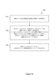
図16は、作業空間、たとえば、図7を参照しながら説明されたグリッド15を備える作業空間中で動作する1つまたは複数の搬送デバイス30の移動の制御を支援するためのコンピュータ実装方法160を示す。
FIG. 16 illustrates a computer-implemented
方法160は、1つまたは複数の画像センサーによってキャプチャされた作業空間の画像表現を取得すること161から開始する。たとえば、1つまたは複数の画像センサーは、作業空間のビューをもつ1つまたは複数のカメラ71の一部である。カメラ71は、図7に示されているように作業空間のグリッド15の上に配設され得る。作業空間の画像は、たとえば、1つまたは複数の画像センサーに通信可能に結合されたインターフェース、たとえばカメラインターフェースまたはCSIにおいて受信される。
The
作業空間の画像表現のターゲット画像部分が、インターフェース、たとえば、画像を受信するために使用されるものとは異なるインターフェースにおいて、取得される162。ターゲット画像部分は、作業空間中のターゲットロケーションにマッピングされる163。マッピング163に基づいて、1つまたは複数の搬送デバイスが入るのを禁止されることになる、作業空間中の除外ゾーンが決定される164。除外ゾーンは、ターゲット画像部分からマッピングされたターゲットロケーションを含む。除外ゾーンを表現する除外ゾーンデータが、作業空間中の除外ゾーンを実装するために制御システム、たとえばマスタコントローラに出力される165。
A target image portion of an image representation of the workspace is acquired 162 at an interface, e.g., a different interface than that used to receive the image. The target image portion is mapped 163 to a target location in the workspace. Based on the
たとえば、作業空間の画像表現を閲覧するユーザが、ターゲット画像部分を取得するように構成されたインターフェースを介してターゲット画像部分を選択する。インターフェースは、たとえば、ユーザが対話するためのユーザインターフェースであり得る。ユーザインターフェースは、画像センサーによってキャプチャされた作業空間の画像表現を表示するためのディスプレイスクリーンを含み得る。ユーザインターフェースは、ユーザがそれを用いてターゲット画像部分を選択することができる入力手段、たとえば、タッチスクリーンディスプレイ、キーボード、マウス、または他の好適な手段をも含み得る。 For example, a user viewing the image representation of the workspace selects a target image portion via an interface configured to obtain the target image portion. The interface may be, for example, a user interface with which the user interacts. The user interface may include a display screen for displaying the image representation of the workspace captured by the image sensor. The user interface may also include input means, for example, a touch screen display, a keyboard, a mouse, or other suitable means, with which the user can select the target image portion.
例では、ターゲット画像部分は、作業空間中の欠陥のある搬送デバイスの少なくとも一部を含む。たとえば、ターゲット画像部分は、画像センサーによってキャプチャされた作業空間の画像から選択された1つまたは複数のピクセルのサブセットである。1つまたは複数のピクセルは、作業空間の画像中に示された欠陥のある搬送デバイスの少なくとも一部に対応する。たとえば、ターゲット画像部分は、画像中に示された欠陥のある搬送デバイス全体を含む。他の例では、ターゲット画像部分は、画像中に示された欠陥のある搬送デバイスの一部に対応する単一のピクセルのみである。 In an example, the target image portion includes at least a portion of the defective transport device in the workspace. For example, the target image portion is a subset of one or more pixels selected from an image of the workspace captured by an image sensor. The one or more pixels correspond to at least a portion of the defective transport device shown in the image of the workspace. For example, the target image portion includes the entire defective transport device shown in the image. In another example, the target image portion is only a single pixel that corresponds to a portion of the defective transport device shown in the image.
たとえば、作業空間がセル17のグリッド15を備える、他の例では、ターゲット画像部分は、セルのグリッド中の所与のセルに対応する。たとえば、ターゲット画像部分は、所与のセルの少なくとも一部に対応する1つまたは複数のピクセルのサブセットである。いくつかの場合には、ターゲット画像部分はセル全体を含み、他の場合には、ターゲット画像部分は、セルの一部に対応する単一のピクセルのみである。
In other examples, for example where the workspace comprises a
上記で説明されたように、いくつかの例では、ユーザは、インターフェース、たとえばユーザインターフェースを介してターゲット画像部分を選択する。しかしながら、他の例では、ターゲット画像部分は、作業空間の画像から欠陥のある搬送デバイスを検出するように構成された物体検出システムから取得される。たとえば、方法160は、物体検出システムが、画像センサーによってキャプチャされた作業空間の画像を取得することと、物体分類モデルを使用して、欠陥のある搬送デバイスが画像データ中に存在することを決定することとを伴う。
As described above, in some examples, a user selects the target image portion via an interface, e.g., a user interface. However, in other examples, the target image portion is obtained from an object detection system configured to detect the defective transport device from an image of the workspace. For example,
物体分類モデル、たとえば物体分類器は、概して図9を参照しながら説明された、例におけるニューラルネットワークを備え、これは、相応に適用されると解釈される。たとえば、物体分類器は、画像センサーによってその後キャプチャされる画像を、作業空間中の欠陥のある搬送デバイスを含んでいるものまたは含んでいないものとして分類するように、作業空間中の欠陥のある搬送デバイスの画像のトレーニングセットを用いてトレーニングされる。 The object classification model, e.g., object classifier, generally comprises a neural network in the example described with reference to FIG. 9, which is taken to apply accordingly. For example, the object classifier is trained with a training set of images of defective transport devices in the workspace to classify images subsequently captured by the image sensor as including or not including defective transport devices in the workspace.
トレーニングされた物体分類器によるポジティブ分類の場合、物体検出システムは、次いで、ターゲット画像部分を出力することができる。たとえば、物体検出システムは、たとえば、バウンディングボックスなどのアノテーションデータを使用して、画像センサーからの元の画像中のターゲット画像部分を示し得る。代替的に、物体検出システムは、画像センサーから受信された元の入力画像のクロップされたバージョンとしてターゲット画像部分を出力し、クロップされたバージョンは、作業空間中の識別された欠陥のある搬送デバイスを含む。 In the case of a positive classification by the trained object classifier, the object detection system can then output the target image portion. For example, the object detection system may indicate the target image portion in the original image from the image sensor using annotation data, such as, for example, a bounding box. Alternatively, the object detection system outputs the target image portion as a cropped version of the original input image received from the image sensor, where the cropped version includes the identified defective conveying device in the workspace.
例では、物体検出システムは、画像データ中の欠陥のある搬送デバイスとそのロケーションとを検出するようにトレーニングされたニューラルネットワークを備える。たとえば、物体検出システムは、欠陥のある搬送デバイスが存在する入力画像の領域を決定する。その領域は、次いで、たとえば、ターゲット画像部分として出力され得る。そのような場合、ニューラルネットワークのトレーニングは、作業空間中の欠陥のある搬送デバイスを示す作業空間のアノテーション付き画像を使用することを伴う。したがって、ニューラルネットワークは、作業空間中の物体を欠陥のある搬送デバイスとして分類することと、欠陥のある搬送デバイスが画像中のどこにあるかを検出すること、すなわち、作業空間の画像に対する欠陥のある搬送デバイスのロケーションを特定することとの両方を行うようにトレーニングされる。 In an example, the object detection system comprises a neural network trained to detect defective transport devices and their locations in image data. For example, the object detection system determines regions of an input image in which defective transport devices are present. The regions may then be output, for example, as target image portions. In such a case, training the neural network involves using annotated images of the workspace that show defective transport devices in the workspace. Thus, the neural network is trained to both classify objects in the workspace as defective transport devices and to detect where the defective transport devices are in the image, i.e., to identify the location of the defective transport devices relative to the image of the workspace.
本明細書で説明されるように、物体検出システムによって出力されたターゲット画像部分は、作業空間中の欠陥のある搬送デバイスの少なくとも一部を含み得る。たとえば、ターゲット画像部分は、画像センサーによってキャプチャされた画像から、たとえば、欠陥のある搬送デバイスのポジティブロケーション特定に基づいて、物体検出システムによって選択された1つまたは複数のピクセルのサブセットである。 As described herein, the target image portion output by the object detection system may include at least a portion of the defective transport device in the workspace. For example, the target image portion is a subset of one or more pixels selected by the object detection system from an image captured by the image sensor based, for example, on a positive location determination of the defective transport device.
例では、決定された除外ゾーンは、離散数(discrete number)のグリッド空間を含む。たとえば、欠陥のある搬送デバイスがグリッド15上の単一のグリッド空間17内にあることが決定され得る。したがって、除外ゾーンは、たとえば、他の搬送デバイスがその単一のグリッド空間に入るのを禁止されるように、そのグリッド空間に延在すると決定される。したがって、他の搬送デバイスと欠陥のある搬送デバイスとの間の衝突が防がれ得る。代替的に、除外ゾーンは、欠陥のある搬送デバイスがあるグリッドセルを中心とするグリッドセルの領域、たとえば3×3セルエリアとして、設定され得る。したがって、除外ゾーンは、欠陥のある搬送デバイスがある、影響を受けるグリッドセルの周りのバッファエリアを含む。いくつかの場合には、欠陥のある搬送デバイスは、たとえば、それが、グリッドセル間に位置するか、倒れたか、またはトラック22と不整合である場合、2つ以上のグリッドセルにわたる。そのような場合、(ターゲットロケーションを含む)マッピングされたグリッドセルの周りのバッファエリアは、マッピングされたグリッドセルのみを除外することに対して除外ゾーンの有効性を改善することができる。バッファエリアのサイズは、たとえば、除外するためのマッピングされたグリッドセルが決定されると適用されることになる、グリッドセルの設定されたエリアとして、あらかじめ決定され得る。追加または代替として、バッファエリアのサイズは、制御システムにおいて除外ゾーンを実装するときの選択可能なパラメータである。
In an example, the determined exclusion zone includes a discrete number of grid spaces. For example, it may be determined that the defective transport device is within a
作業空間中で動作する搬送デバイスの移動をリモートで制御する制御システム、たとえばマスタコントローラは、方法160の一部としての除外ゾーンデータ出力165に基づいて除外ゾーンを実装することができる。たとえば、1つまたは複数の搬送デバイス30の各々が、制御システム、たとえば中央コンピュータの制御下でリモートで動作可能である。グリッド15上の1つまたは複数の搬送デバイス30の移動を制御するために、たとえば、1つまたは複数の基地局を実装する、ワイヤレス通信ネットワークを介して、制御システムから1つまたは複数の搬送デバイス30に命令が送られ得る。
A control system, e.g., a master controller, remotely controlling the movement of the transport devices operating in the workspace can implement the exclusion zone based on the exclusion
各搬送デバイス30中のコントローラが、その移動を制御するために、搬送デバイス、たとえば車両32の様々な駆動機構を制御するように構成される。たとえば、命令は、所与の搬送デバイスについての定義された軌道にカプセル化され得る、グリッド構造15のX-Y平面における様々な移動を含む。したがって、除外ゾーンは、定義された軌道が、除外ゾーンデータによって表現された除外ゾーンを回避するように、中央制御システム、たとえばマスタコントローラによって実装され得る。たとえば、除外ゾーンが実装されたとき、グリッド上の1つまたは複数の搬送デバイス30に対応する1つまたは複数のそれぞれの軌道が、除外ゾーンを回避するように更新される。
A controller in each
例では、ターゲット画像部分(たとえば画像中の1つまたは複数のピクセル)をターゲットロケーション(たとえばグリッド構造上のポイント)にマッピングすることが、作業空間の画像のひずみを逆にすることを伴う。たとえば、画像センサーが超広角レンズと組み合わせて使用される場合、そのレンズは、作業空間のビューをひずませる。したがって、そのひずみは、たとえば、画像ピクセルとグリッドポイントとの間のマッピングの一部として、逆にされる。逆ひずみモデルが、この目的でターゲット画像部分に適用され得る。以前の例における画像からグリッドへのマッピングアルゴリズムの説明は、ここで相応に適用される。たとえば、ターゲット画像部分をターゲットグリッドロケーションにマッピングすることが、本明細書で説明される、画像からグリッドへのマッピングアルゴリズムを適用することを伴う。 In an example, mapping a target image portion (e.g., one or more pixels in an image) to a target location (e.g., a point on a grid structure) involves inverting a distortion of the image of the workspace. For example, if an image sensor is used in combination with an ultra-wide-angle lens, the lens distorts the view of the workspace. Thus, the distortion is reversed, for example, as part of the mapping between image pixels and grid points. An inverse distortion model may be applied to the target image portion for this purpose. The description of the image-to-grid mapping algorithm in the previous example applies here accordingly. For example, mapping a target image portion to a target grid location involves applying an image-to-grid mapping algorithm described herein.
作業空間中の搬送デバイス移動を制御するための制御システムを支援する方法160は、実施形態では支援システムによって実装される。たとえば、支援システムは、作業空間の画像表現をキャプチャするための1つまたは複数の画像センサーと、画像のターゲット画像部分を取得するためのインターフェースとを含む。支援システムは、方法160の、マッピングすること163、決定すること164、および出力する165のステップを実施するように構成される。たとえば、支援システムは、制御システム、たとえばマスタコントローラが、入力として受信し、作業空間中で実装するために、除外ゾーンデータを出力する。除外ゾーンデータは、支援システムと制御システムとの間で直接移され得るか、または制御システムによってアクセス可能なストレージに支援システムによって記憶され得る。
The
支援システムを採用する実施形態では、作業空間中の欠陥のある搬送デバイスを検出するように構成された物体検出システムは、たとえば、支援システムの一部である。支援システムのインターフェースは、例において説明されるように、物体検出システムからターゲット画像部分を取得し得る。 In an embodiment employing an assistance system, an object detection system configured to detect a defective transport device in the workspace is, for example, part of the assistance system. An interface of the assistance system may obtain a target image portion from the object detection system as described in the examples.
支援システムは、作業空間と、作業空間中の搬送デバイス移動を制御するための制御システムとを含む、保管システム1、たとえば図7に示されている例に組み込まれ得る。図7を参照する例において説明されたように、作業空間は、X方向に延在する平行なトラックの第1のセット22aと、実質的に水平な平面において第1のセットに直交する、Y方向に延在する平行なトラックの第2のセット22bとによって形成された、グリッド15を含む。グリッド15は、複数のグリッド空間17を含み、1つまたは複数の搬送デバイス30は、単一のグリッド空間17のフットプリント内でトラック22の下にスタックされたコンテナ10を取り扱うために、トラック上で周辺を選択的に移動するように配置される。各搬送デバイス30は、1つのグリッド空間を占有する所与の搬送デバイスが、隣接するグリッド空間を占有するかまたは横断する別の搬送デバイスを妨害しないように、単一のグリッド空間17のみを占有するフットプリントを有し得る。
The support system may be incorporated into a
例において説明されるように、除外ゾーンは、離散数のグリッド空間17に対応することができる。たとえば、支援システムは、グリッド15の上のカメラ71によってキャプチャされた画像中で検出された欠陥のある搬送デバイス30に対応する、グリッド15上のターゲットロケーションを決定する。ターゲットロケーションは、たとえば、前の例において説明された較正方法に基づいて、グリッド全体に対するグリッド空間座標にコンバートされ、除外ゾーンが、ターゲットロケーションのグリッド空間に基づいて決定される。たとえば、除外ゾーンは、ターゲットロケーションの少なくともグリッド空間を含むが、例において説明されるように、たとえばバッファエリアとして、さらなる周囲グリッド空間を含み得る。保管システムの制御システム、たとえばマスタコントローラは、作業空間中で動作する搬送デバイス30が除外ゾーンに入るのを禁止されるように、支援システムによって決定された除外ゾーンデータに基づいて、作業空間中の除外ゾーンを実装するように構成される。
As described in the example, the exclusion zone can correspond to a discrete number of
上記の例は、例示的な例として理解されるべきである。さらなる例が想定される。たとえば、グリッド15の上に配設されたカメラ71は、多くの例では超広角カメラとして説明された。しかしながら、カメラ71は広角カメラであり得、これは、超広角レンズよりも比較的長い焦点距離を有する広角レンズを含むが、人間観測者にとって「自然」に見える視野を再現する通常レンズと比較して、依然としてひずみをもたらす。
The above examples should be understood as illustrative examples. Further examples are envisioned. For example, the
同様に、説明される例は、「画像」または「画像データ」を取得および処理することを含む。そのような画像は、いくつかの場合には、たとえば、フレームのシーケンスを備えるビデオから選択された、ビデオフレームであり得る。ビデオは、本明細書で説明されるようにグリッドの上に位置するカメラによってキャプチャされ得る。したがって、画像を取得および処理することは、ビデオ、たとえばビデオストリームからのフレームを取得および処理することを含むと解釈されるべきである。たとえば、説明されるニューラルネットワークは、複数の画像を備えるビデオストリーム中の物体(たとえば、搬送デバイス、その上のIDマーカーなど)のインスタンスを検出するようにトレーニングされ得る。さらに、搬送デバイス上のIDマーカーを検出することを伴う説明される例では、画像データは、第1のニューラルネットワークと第2のニューラルネットワークとを連続して用いて処理される。しかしながら、代替例では、第1のニューラルネットワークと第2のニューラルネットワークとは、たとえば単一のニューラルネットワークとして、エンドツーエンドIDマーカー検出パイプラインまたはアーキテクチャにおいてマージされる。たとえば、X方向に延在する平行なトラックの第1のセットと、実質的に水平な平面において第1のセットに直交する、Y方向に延在する平行なトラックの第2のセットとによって形成された、グリッドを備える作業空間中の搬送デバイス上の識別マーカーを検出する方法であって、グリッドが、複数のグリッド空間を備え、ここにおいて、1つまたは複数の搬送デバイスが、トラック上でX方向またはY方向のうちの少なくとも1つにおいて選択的に移動することと、単一のグリッド空間のフットプリント内でトラックの下にスタックされたコンテナを取り扱うこととを行うように配置される、方法も提供される。本方法は、1つまたは複数の搬送デバイスのうちの搬送デバイスを含む画像部分を表現する画像データを取得することと、画像中の搬送デバイス上の識別マーカーのインスタンスを検出すること、および画像中の、識別マーカーに関連する、マーカー情報を認識することを行うようにトレーニングされた、少なくとも1つのニューラルネットワークを用いて画像データを処理することと、第2のニューラルネットワークによって決定されたマーカー情報を表現するマーカーデータを出力することとを備える。この代替例による、検出システムのコンテキストでは、1つまたは複数のプロセッサは、画像中の搬送デバイス上の識別マーカーのインスタンスを検出すること、および画像中の、識別マーカーに関連する、マーカー情報を認識することを行うようにトレーニングされた、少なくとも1つのニューラルネットワークを実装するように構成される。検出システムは、搬送デバイス上の識別マーカー上に存在する(たとえばそれに符号化された)マーカー情報(たとえば搬送デバイスの記述子)を表現するマーカーデータ(たとえばテキストストリングまたはコード)を生成するために、少なくとも1つのニューラルネットワークを用いて、取得された画像データを処理することと、マーカーデータを出力することとを行うように構成される。 Similarly, the described examples include acquiring and processing "images" or "image data." Such images may in some cases be video frames, e.g., selected from a video comprising a sequence of frames. The video may be captured by a camera located on a grid as described herein. Thus, acquiring and processing images should be interpreted as including acquiring and processing a video, e.g., a frame from a video stream. For example, the described neural network may be trained to detect instances of an object (e.g., a transport device, an ID marker thereon, etc.) in a video stream comprising multiple images. Furthermore, in the described example involving detecting an ID marker on a transport device, the image data is processed using a first neural network and a second neural network in succession. However, in alternative examples, the first neural network and the second neural network are merged in an end-to-end ID marker detection pipeline or architecture, e.g., as a single neural network. For example, there is also provided a method of detecting identification markers on a transport device in a workspace comprising a grid formed by a first set of parallel tracks extending in an X direction and a second set of parallel tracks extending in a Y direction orthogonal to the first set in a substantially horizontal plane, the grid comprising a plurality of grid spaces, where one or more transport devices are arranged to selectively move in at least one of the X or Y directions on the tracks and to handle containers stacked under the tracks within the footprint of a single grid space. The method comprises obtaining image data representative of an image portion including one or more of the transport devices, processing the image data with at least one neural network trained to detect instances of identification markers on the transport devices in the image and to recognize marker information in the image associated with the identification markers, and outputting marker data representative of the marker information determined by the second neural network. In the context of the detection system according to this alternative, the one or more processors are configured to implement at least one neural network trained to detect instances of identification markers on the carrier device in the image and to recognize marker information associated with the identification markers in the image. The detection system is configured to process the acquired image data with the at least one neural network to generate marker data (e.g., a text string or code) representative of the marker information (e.g., a descriptor of the carrier device) present on (e.g., encoded on) the identification marker on the carrier device, and to output the marker data.
さらに、搬送デバイスのロケーション特定に関する説明される例では、グリッド15上の検出された搬送デバイス30のロケーションは、画像中の検出された搬送デバイスを示すアノテーションデータを、複数の仮想の搬送するデバイスに対応するさらなるアノテーションデータと比較することによって、決定可能である。代替例では、グリッド15上の検出された搬送デバイス30のロケーションは、2つのステッププロセスにおいて決定され得る。第1に、複数の仮想搬送デバイスはフィルタ処理され、これは、たとえば、搬送デバイス30の予測/推論データと、複数の仮想搬送デバイスのすべての可能なロケーションのアノテーションデータとを使用して、和集合の共通部分(IoU)値を計算することを含む。たとえば、所定のしきい値よりも小さい計算されたIoU値をもつ仮想搬送デバイスが、フィルタで除去される。第2に、すべての残りの仮想搬送デバイスが、カメラの視野の中心に最も近い距離によって(たとえば昇順で)ソートされ、第1の(たとえば最も近い)仮想搬送デバイスが、マッピングとしてとられる。搬送デバイス30のグリッドロケーションは、次いで、たとえば、マッピングされた仮想搬送デバイスのアノテーションデータがそこから作成される、グリッドロケーションに設定される。
Furthermore, in the described example of locating the transport device, the location of the detected
データを記憶するためにストレージを採用する例では、ストレージは、DDR-SDRAM(ダブルデータレート同期ダイナミックランダムアクセスメモリ)などのランダムアクセスメモリ(RAM)であり得る。他の例では、ストレージ330は、読取り専用メモリ(ROM)などの不揮発性メモリ、またはフラッシュメモリなどのソリッドステートドライブ(SSD)を含み得る。ストレージは、いくつかの場合には、他の記憶媒体、たとえば、磁気、光またはテープ媒体、コンパクトディスク(CD)、デジタル多用途ディスク(DVD)または他のデータ記憶媒体を含む。ストレージは、関係するシステムから取外し可能であるか、または取外し不可能であり得る。 In examples employing storage to store data, the storage may be random access memory (RAM), such as DDR-SDRAM (Double Data Rate Synchronous Dynamic Random Access Memory). In other examples, storage 330 may include non-volatile memory, such as read-only memory (ROM), or a solid-state drive (SSD), such as flash memory. Storage may in some cases include other storage media, for example, magnetic, optical or tape media, compact discs (CDs), digital versatile discs (DVDs), or other data storage media. Storage may be removable or non-removable from the associated system.
データ処理を採用する例では、プロセッサが、関係するシステムの一部として採用され得る。プロセッサは、中央処理ユニット(CPU)、マイクロプロセッサ、グラフィックス処理ユニット(GPU)、デジタル信号プロセッサ(DSP)、特定用途向け集積回路(ASIC)、フィールドプログラマブルゲートアレイ(FPGA)または別のプログラマブル論理デバイス、個別ゲートまたはトランジスタ論理、個別ハードウェア構成要素、あるいは本明細書で説明されるデータ処理機能を実施するように設計されたそれらの任意の好適な組合せなど、汎用プロセッサであり得る。 In examples employing data processing, a processor may be employed as part of the system concerned. The processor may be a general-purpose processor, such as a central processing unit (CPU), a microprocessor, a graphics processing unit (GPU), a digital signal processor (DSP), an application specific integrated circuit (ASIC), a field programmable gate array (FPGA) or another programmable logic device, discrete gate or transistor logic, discrete hardware components, or any suitable combination thereof designed to perform the data processing functions described herein.
ニューラルネットワークを伴う例では、専用プロセッサが、関係するシステムの一部として採用され得る。専用プロセッサは、NPU、ニューラルネットワークアクセラレータ(NNA)、またはニューラルネットワーク機能について専用化されたハードウェアアクセラレータの他のバージョンであり得る。追加または代替として、ニューラルネットワーク処理作業負荷は、1つまたは複数の標準プロセッサ、たとえばCPUまたはGPUによって、少なくとも部分的に共有され得る。 In examples involving neural networks, a dedicated processor may be employed as part of the system involved. The dedicated processor may be an NPU, a Neural Network Accelerator (NNA), or other version of a hardware accelerator dedicated to neural network functions. Additionally or alternatively, the neural network processing workload may be at least partially shared by one or more standard processors, e.g., a CPU or GPU.
「アイテム」という用語が説明全体にわたって使用されたが、それは、ケース、アセット、ユニット、パレット、機器など、他の用語を含むことが想定される。「アノテーションデータ」という用語が、説明全体にわたって同様に使用された。しかしながら、その用語は、代替の命名法では予測データまたは推論データと対応することが想定される。たとえば、(たとえばニューラルネットワークを備える)物体検出モデルは、モデルについてのグランドトゥルース、たとえば、100%または正規化されたときに1の信頼性をもつ予測または推論として働く、アノテーション付き画像、たとえば、バウンディングボックスなどのアノテーションをもつ画像を使用して、トレーニングされ得る。これらのアノテーションは、たとえば、モデルをトレーニングする目的のために人間によって行われ得る。したがって、本開示の物体検出は、画像中の搬送デバイスの予測または推論を示すために、(たとえば「アノテーションデータ」の代わりに)予測データまたは推論データを出力することを伴うと解釈され得る。予測データまたは推論データは、画像に適用されるアノテーション、たとえばバウンディングボックスおよび/またはラベルとして表現され得る。予測データまたは推論データは、たとえば、画像中の搬送デバイスの予測または推論に関連する信頼性を含む。アノテーションは、たとえば、生成された予測データまたは推論データに基づいて画像に適用され得る。たとえば、画像は、たとえば、割合値、または0から1の間の正規化された値として、予測の信頼性レベルを示すラベルをもつ、予測された搬送デバイスを囲むバウンディングボックスを含むように更新され得る。 The term "item" has been used throughout the description, but it is envisioned to include other terms, such as case, asset, unit, pallet, equipment, etc. The term "annotation data" has been used throughout the description as well. However, it is envisioned that the term corresponds to prediction data or inference data in alternative nomenclature. For example, an object detection model (e.g., comprising a neural network) may be trained using annotated images, e.g., images with annotations such as bounding boxes, that serve as ground truth for the model, e.g., predictions or inferences with a confidence of 100% or 1 when normalized. These annotations may be made by humans, e.g., for the purpose of training the model. Thus, object detection in the present disclosure may be interpreted as involving outputting prediction or inference data (e.g., instead of "annotation data") to indicate a prediction or inference of a conveying device in an image. The prediction or inference data may be expressed as annotations, e.g., bounding boxes and/or labels, applied to the image. The prediction or inference data may include, for example, a confidence associated with a prediction or inference of a conveying device in an image. Annotations may be applied to the image, for example, based on the generated prediction or inference data. For example, the image may be updated to include a bounding box surrounding the predicted transport device with a label indicating the confidence level of the prediction, for example, as a percentage value or a normalized value between 0 and 1.
また、任意の一例に関して説明される特徴が、単独で、または説明される他の特徴と組み合わせて使用され得、また、例のうちの任意の他のものの1つまたは複数の特徴と組み合わせて、または例のうちの任意の他のものの任意の組合せで使用され得ることを理解されたい。さらに、上記で説明されない等価物および修正も、添付の特許請求の範囲の範囲から逸脱することなく採用され得る。
以下に本願の出願当初の特許請求の範囲に記載された発明を付記する。
[C1]
作業空間中で動作する1つまたは複数の搬送デバイスの移動の制御を支援するためのコンピュータ実装方法であって、前記方法は、
1つまたは複数の画像センサーによってキャプチャされた前記作業空間の画像表現を取得することと、
インターフェースにおいて、前記作業空間の前記画像表現のターゲット画像部分を取得することと、
前記ターゲット画像部分を前記作業空間中のターゲットロケーションにマッピングすることと、
前記マッピングに基づいて、前記1つまたは複数の搬送デバイスが入るのを禁止されることになる、前記ターゲットロケーションを備える、前記作業空間中の除外ゾーンを決定することと、
前記作業空間中の前記除外ゾーンを実装するために、前記除外ゾーンを表現する除外ゾーンデータを、制御システムに出力することと
を備える、コンピュータ実装方法。
[C2]
前記ターゲット画像部分が、前記インターフェースを介して、前記作業空間の前記画像表現を閲覧するユーザによって選択される、C1に記載の方法。
[C3]
前記ターゲット画像部分が、前記作業空間中の欠陥のある搬送デバイスの少なくとも一部を備える、C2に記載の方法。
[C4]
前記作業空間がセルのグリッドを備え、前記1つまたは複数の搬送デバイスが、前記グリッド上の前記セル間で移動するように配置され、ここにおいて、前記ターゲット画像部分が、セルの前記グリッド中の所与のセルを備える、C1または2に記載の方法。
[C5]
前記ターゲット画像部分が、前記作業空間を表現する画像データに基づいて前記作業空間中の欠陥のある搬送デバイスを検出するように構成された物体検出システムから取得される、C1に記載の方法。
[C6]
前記ターゲット画像部分が、前記作業空間中の欠陥のある搬送デバイスの少なくとも一部を備える、C5に記載の方法。
[C7]
前記方法は、
前記物体検出システムにおいて、前記1つまたは複数の画像センサーによってキャプチャされた前記作業空間を表現する前記画像データを取得することと、
物体分類モデルを使用して、前記欠陥のある搬送デバイスが前記画像データ中に存在すると決定することと、
前記作業空間中で検出された前記欠陥のある搬送デバイスの少なくとも一部を備える前記ターゲット画像部分を出力することと
を備える、C6に記載の方法。
[C8]
前記作業空間が、X方向に延在する平行なトラックの第1のセットと、実質的に水平な平面において前記第1のセットに直交する、Y方向に延在する平行なトラックの第2のセットとによって形成された、グリッドを備え、前記グリッドが、複数のグリッド空間を備え、
前記搬送デバイスが、前記トラック上で前記X方向または前記Y方向のうちの少なくとも1つにおいて選択的に移動することと、単一のグリッド空間のフットプリント内で前記トラックの下にスタックされたコンテナを取り扱うこととを行うように配置される、
C1から7のいずれかに記載の方法。
[C9]
前記1つまたは複数の搬送デバイスは、1つのグリッド空間を占有する所与の搬送デバイスが、隣接するグリッド空間を占有するかまたは横断する別の搬送デバイスを妨害しないように、各々、単一のグリッド空間のみを占有するフットプリントを有する、C8に記載の方法。
[C10]
前記除外ゾーンが、離散数のグリッド空間を備える、C8または9に記載の方法。
[C11]
前記1つまたは複数の搬送デバイスが前記除外ゾーンに入るのを禁止されるように、前記制御システムにおいて前記除外ゾーンを実装することを備える、C1から10のいずれかに記載の方法。
[C12]
前記マッピングが、前記作業空間の前記画像表現のひずみを逆にすることを備える、C1から11のいずれかに記載の方法。
[C13]
作業空間中の搬送デバイス移動を制御するための制御システムを支援するための支援システムであって、前記支援システムが、
前記作業空間の画像表現をキャプチャするための画像センサーと、
前記作業空間の前記画像表現のターゲット画像部分を取得するためのインターフェースと
を備え、
ここにおいて、前記支援システムは、
前記ターゲット画像部分を前記作業空間中のターゲットロケーションにマッピングすることと、
前記マッピングに基づいて、1つまたは複数の搬送デバイスが入るのを禁止される、前記ターゲットロケーションを備える、前記作業空間中の除外ゾーンを決定することと、
前記作業空間中の前記除外ゾーンを実装するために、前記除外ゾーンを表現する除外ゾーンデータを、前記制御システムに出力することと
を行うように構成された、支援システム。
[C14]
前記インターフェースは、前記作業空間の前記画像表現を閲覧するユーザが前記ターゲット画像部分を選択するためのものである、C13に記載の支援システム。
[C15]
前記作業空間を表現する画像データに基づいて前記作業空間中の欠陥のある搬送デバイスを検出するように構成された物体検出システムを備え、
ここにおいて、前記インターフェースが、前記物体検出システムから前記ターゲット画像部分を取得する、
C13または14に記載の支援システム。
[C16]
前記ターゲット画像部分が、前記作業空間中の欠陥のある搬送デバイスの少なくとも一部を備える、C15に記載の支援システム。
[C17]
前記物体検出システムは、
前記画像センサーによってキャプチャされた前記作業空間を表現する前記画像データを取得することと、
物体分類モデルを使用して、前記欠陥のある搬送デバイスが前記画像データ中に存在すると決定することと、
前記作業空間中で検出された前記欠陥のある搬送デバイスの少なくとも一部を備える前記ターゲット画像部分を出力することと
を行うように構成された、C15または16に記載の支援システム。
[C18]
作業空間と、
C13から17のいずれか一項に記載の支援システムと、
前記作業空間中の搬送デバイス移動を制御するための制御システムと
を備える、保管システムであって、
ここにおいて、前記作業空間が、X方向に延在する平行なトラックの第1のセットと、実質的に水平な平面において前記第1のセットに直交する、Y方向に延在する平行なトラックの第2のセットとによって形成された、グリッドを備え、前記グリッドが、複数のグリッド空間を備え、
ここにおいて、1つまたは複数の搬送デバイスが、前記トラック上で前記X方向または前記Y方向のうちの少なくとも1つにおいて選択的に移動することと、単一のグリッド空間のフットプリント内で前記トラックの下にスタックされたコンテナを取り扱うこととを行うように配置される、保管システム。
[C19]
前記1つまたは複数の搬送デバイスは、1つのグリッド空間を占有する所与の搬送デバイスが、隣接するグリッド空間を占有するかまたは横断する別の搬送デバイスを妨害しないように、各々、単一のグリッド空間のみを占有するフットプリントを有する、C18に記載の保管システム。
[C20]
除外ゾーンが、離散数のグリッド空間を備える、C18または19に記載の保管システム。
[C21]
前記制御システムは、前記支援システムから除外ゾーンデータを受信することと、前記1つまたは複数の搬送デバイスが前記除外ゾーンに入るのを禁止されるように、前記作業空間中の前記除外ゾーンを実装することとを行うように構成された、C18から20のいずれか一項に記載の保管システム。
It should also be understood that features described with respect to any one example may be used alone or in combination with other features described, and may also be used in combination with one or more features of any other of the examples, or in any combination of any other of the examples. Moreover, equivalents and modifications not described above may be employed without departing from the scope of the appended claims.
The invention as described in the claims of the original application is set forth below.
[C1]
1. A computer-implemented method for assisting in controlling movement of one or more transport devices operating in a workspace, the method comprising:
obtaining an image representation of the workspace captured by one or more image sensors;
obtaining, at an interface, a target image portion of the image representation of the workspace;
mapping the target image portion to a target location in the workspace;
determining an exclusion zone in the workspace comprising the target location where the one or more transport devices will be prohibited from entering based on the mapping;
outputting exclusion zone data representative of said exclusion zone to a control system for implementing said exclusion zone in said workspace;
A computer-implemented method comprising:
[C2]
The method of claim C1, wherein the target image portion is selected by a user viewing the image representation of the workspace via the interface.
[C3]
The method of C2, wherein the target image portion comprises at least a portion of a defective transport device in the workspace.
[C4]
A method as described in C1 or C2, wherein the workspace comprises a grid of cells and the one or more transport devices are arranged to move between the cells on the grid, and wherein the target image portion comprises a given cell in the grid of cells.
[C5]
The method of claim C1, wherein the target image portion is obtained from an object detection system configured to detect a defective transport device in the workspace based on image data representing the workspace.
[C6]
The method of C5, wherein the target image portion comprises at least a portion of a defective transport device in the workspace.
[C7]
The method comprises:
acquiring, in the object detection system, the image data representative of the workspace captured by the one or more image sensors;
determining that the defective transport device is present in the image data using an object classification model;
outputting the target image portion comprising at least a portion of the defective transport device detected in the workspace;
The method of claim 6, comprising:
[C8]
the workspace comprises a grid formed by a first set of parallel tracks extending in an X direction and a second set of parallel tracks extending in a Y direction orthogonal to the first set in a substantially horizontal plane, the grid comprising a plurality of grid spaces;
the transport device is arranged to selectively move on the track in at least one of the X-direction or the Y-direction and to handle containers stacked beneath the track within a footprint of a single grid space.
The method according to any one of C1 to 7.
[C9]
The method of claim 8, wherein the one or more transport devices each have a footprint that occupies only a single grid space, such that a given transport device occupying one grid space does not interfere with another transport device occupying or crossing an adjacent grid space.
[C10]
The method of any one of C8 to 9, wherein the exclusion zone comprises a discrete number of grid spaces.
[C11]
A method according to any of C1 to 10, comprising implementing the exclusion zone in the control system such that the one or more transport devices are prohibited from entering the exclusion zone.
[C12]
A method according to any of C1 to 11, wherein the mapping comprises inverting a distortion of the image representation of the workspace.
[C13]
1. An assistance system for assisting a control system for controlling movement of a transport device in a workspace, said assistance system comprising:
an image sensor for capturing an image representation of the workspace;
an interface for obtaining a target image portion of the image representation of the workspace;
Equipped with
wherein the assistance system comprises:
mapping the target image portion to a target location in the workspace;
determining an exclusion zone in the workspace comprising the target location, within which one or more transport devices are prohibited from entering, based on the mapping;
outputting exclusion zone data representative of the exclusion zone to the control system for implementing the exclusion zone in the workspace;
The assistance system is configured to:
[C14]
The assistance system of C13, wherein the interface is for a user viewing the image representation of the workspace to select the target image portion.
[C15]
an object detection system configured to detect a defective transport device in the workspace based on image data representing the workspace;
wherein the interface acquires the target image portion from the object detection system.
The support system according to C13 or 14.
[C16]
The assistance system of
[C17]
The object detection system includes:
acquiring the image data representative of the workspace captured by the image sensor;
determining that the defective transport device is present in the image data using an object classification model;
outputting the target image portion comprising at least a portion of the defective transport device detected in the workspace;
The support system according to C15 or 16, configured to perform the above.
[C18]
The working space and
An assistance system according to any one of claims 13 to 17,
a control system for controlling movement of the transport device through the workspace;
A storage system comprising:
wherein the workspace comprises a grid formed by a first set of parallel tracks extending in an X direction and a second set of parallel tracks extending in a Y direction orthogonal to the first set in a substantially horizontal plane, the grid comprising a plurality of grid spaces;
11. A storage system, wherein one or more transport devices are arranged to selectively move on said track in at least one of said X-direction or said Y-direction and to handle containers stacked beneath said track within the footprint of a single grid space.
[C19]
The storage system of C18, wherein the one or more transport devices each have a footprint that occupies only a single grid space, such that a given transport device occupying one grid space does not interfere with another transport device occupying or crossing an adjacent grid space.
[C20]
20. The storage system of
[C21]
A storage system as described in any one of C18 to 20, wherein the control system is configured to receive exclusion zone data from the support system and implement the exclusion zone in the workspace such that the one or more transport devices are prohibited from entering the exclusion zone.
Claims (21)
1つまたは複数の画像センサーによってキャプチャされた前記作業空間の画像表現を取得することと、
インターフェースにおいて、前記作業空間の前記画像表現のターゲット画像部分を取得することと、
前記ターゲット画像部分を前記作業空間中のターゲットロケーションにマッピングすることと、
前記マッピングに基づいて、前記1つまたは複数の搬送デバイスが入るのを禁止されることになる、前記ターゲットロケーションを備える、前記作業空間中の除外ゾーンを決定することと、
前記作業空間中の前記除外ゾーンを実装するために、前記除外ゾーンを表現する除外ゾーンデータを、制御システムに出力することと
を備える、コンピュータ実装方法。 1. A computer-implemented method for assisting in controlling movement of one or more transport devices operating in a workspace, the method comprising:
obtaining an image representation of the workspace captured by one or more image sensors;
obtaining, at an interface, a target image portion of the image representation of the workspace;
mapping the target image portion to a target location in the workspace;
determining an exclusion zone in the workspace comprising the target location within which the one or more transport devices will be prohibited from entering based on the mapping;
and outputting exclusion zone data representative of the exclusion zone to a control system for implementing the exclusion zone in the workspace.
前記物体検出システムにおいて、前記1つまたは複数の画像センサーによってキャプチャされた前記作業空間を表現する前記画像データを取得することと、
物体分類モデルを使用して、前記欠陥のある搬送デバイスが前記画像データ中に存在すると決定することと、
前記作業空間中で検出された前記欠陥のある搬送デバイスの少なくとも一部を備える前記ターゲット画像部分を出力することと
を備える、請求項6に記載の方法。 The method comprises:
acquiring, in the object detection system, the image data representative of the workspace captured by the one or more image sensors;
determining that the defective transport device is present in the image data using an object classification model;
and outputting the target image portion comprising at least a portion of the defective transport device detected in the workspace.
前記搬送デバイスが、前記トラック上で前記X方向または前記Y方向のうちの少なくとも1つにおいて選択的に移動することと、単一のグリッド空間のフットプリント内で前記トラックの下にスタックされたコンテナを取り扱うこととを行うように配置される、
請求項1から7のいずれかに記載の方法。 the workspace comprises a grid formed by a first set of parallel tracks extending in an X-direction and a second set of parallel tracks extending in a Y-direction orthogonal to the first set in a substantially horizontal plane, the grid comprising a plurality of grid spaces;
the transport device is arranged to selectively move on the track in at least one of the X-direction or the Y-direction and to handle containers stacked beneath the track within a footprint of a single grid space.
The method according to any one of claims 1 to 7.
前記作業空間の画像表現をキャプチャするための画像センサーと、
前記作業空間の前記画像表現のターゲット画像部分を取得するためのインターフェースと
を備え、
ここにおいて、前記支援システムは、
前記ターゲット画像部分を前記作業空間中のターゲットロケーションにマッピングすることと、
前記マッピングに基づいて、1つまたは複数の搬送デバイスが入るのを禁止される、前記ターゲットロケーションを備える、前記作業空間中の除外ゾーンを決定することと、
前記作業空間中の前記除外ゾーンを実装するために、前記除外ゾーンを表現する除外ゾーンデータを、前記制御システムに出力することと
を行うように構成された、支援システム。 1. An assistance system for assisting a control system for controlling movement of a transport device in a workspace, said assistance system comprising:
an image sensor for capturing an image representation of the workspace;
an interface for obtaining a target image portion of the image representation of the workspace;
wherein the assistance system comprises:
mapping the target image portion to a target location in the workspace;
determining an exclusion zone in the workspace comprising the target location, within which one or more transport devices are prohibited from entering, based on the mapping;
and outputting exclusion zone data representative of the exclusion zone to the control system for implementing the exclusion zone in the workspace.
ここにおいて、前記インターフェースが、前記物体検出システムから前記ターゲット画像部分を取得する、
請求項13に記載の支援システム。 an object detection system configured to detect a defective transport device in the workspace based on image data representing the workspace;
wherein the interface acquires the target image portion from the object detection system.
The support system according to claim 13 .
前記画像センサーによってキャプチャされた前記作業空間を表現する前記画像データを取得することと、
物体分類モデルを使用して、前記欠陥のある搬送デバイスが前記画像データ中に存在すると決定することと、
前記作業空間中で検出された前記欠陥のある搬送デバイスの少なくとも一部を備える前記ターゲット画像部分を出力することと
を行うように構成された、請求項15に記載の支援システム。 The object detection system includes:
acquiring the image data representative of the workspace captured by the image sensor;
determining that the defective transport device is present in the image data using an object classification model;
The assistance system of claim 15 , configured to: and output the target image portion comprising at least a portion of the defective transport device detected in the workspace.
請求項13から17のいずれか一項に記載の支援システムと、
前記作業空間中の搬送デバイス移動を制御するための制御システムと
を備える、保管システムであって、
ここにおいて、前記作業空間が、X方向に延在する平行なトラックの第1のセットと、実質的に水平な平面において前記第1のセットに直交する、Y方向に延在する平行なトラックの第2のセットとによって形成された、グリッドを備え、前記グリッドが、複数のグリッド空間を備え、
ここにおいて、1つまたは複数の搬送デバイスが、前記トラック上で前記X方向または前記Y方向のうちの少なくとも1つにおいて選択的に移動することと、単一のグリッド空間のフットプリント内で前記トラックの下にスタックされたコンテナを取り扱うこととを行うように配置される、保管システム。 The working space and
An assistance system according to any one of claims 13 to 17;
a control system for controlling transport device movement in the workspace,
wherein the workspace comprises a grid formed by a first set of parallel tracks extending in an X direction and a second set of parallel tracks extending in a Y direction orthogonal to the first set in a substantially horizontal plane, the grid comprising a plurality of grid spaces;
11. A storage system, wherein one or more transport devices are arranged to selectively move on said track in at least one of said X-direction or said Y-direction and to handle containers stacked beneath said track within the footprint of a single grid space.
Applications Claiming Priority (3)
| Application Number | Priority Date | Filing Date | Title |
|---|---|---|---|
| GB2117095.6 | 2021-11-26 | ||
| GBGB2117095.6A GB202117095D0 (en) | 2021-11-26 | 2021-11-26 | Determining an exclusion zone in a workspace of transport devices |
| PCT/EP2022/083364 WO2023094634A1 (en) | 2021-11-26 | 2022-11-25 | Determining an exclusion zone in a workspace of transport devices |
Publications (2)
| Publication Number | Publication Date |
|---|---|
| JP2024545611A JP2024545611A (en) | 2024-12-10 |
| JP7686888B2 true JP7686888B2 (en) | 2025-06-02 |
Family
ID=80038481
Family Applications (1)
| Application Number | Title | Priority Date | Filing Date |
|---|---|---|---|
| JP2024531347A Active JP7686888B2 (en) | 2021-11-26 | 2022-11-25 | Determining an exclusion zone in the working space of a transport device |
Country Status (9)
| Country | Link |
|---|---|
| US (1) | US20250026565A1 (en) |
| EP (1) | EP4437470A1 (en) |
| JP (1) | JP7686888B2 (en) |
| KR (1) | KR20240116497A (en) |
| CN (1) | CN118511186A (en) |
| AU (1) | AU2022397829B2 (en) |
| CA (1) | CA3239647A1 (en) |
| GB (2) | GB202117095D0 (en) |
| WO (1) | WO2023094634A1 (en) |
Citations (5)
| Publication number | Priority date | Publication date | Assignee | Title |
|---|---|---|---|---|
| JP2005328333A (en) | 2004-05-14 | 2005-11-24 | Hitachi Kokusai Electric Inc | Monitoring system |
| JP2017214197A (en) | 2016-05-31 | 2017-12-07 | 株式会社リコー | Management system, management method, and information processing apparatus |
| US20210093134A1 (en) | 2019-10-01 | 2021-04-01 | Lg Electronics Inc. | Robot cleaner and method for determining cleaning path |
| JP2021509653A (en) | 2018-01-10 | 2021-04-01 | オカド・イノベーション・リミテッド | Controllers and methods for transport devices |
| JP2022052494A (en) | 2020-09-23 | 2022-04-04 | 株式会社東芝 | Operation controller and operation control system |
Family Cites Families (6)
| Publication number | Priority date | Publication date | Assignee | Title |
|---|---|---|---|---|
| US5979633A (en) | 1997-04-25 | 1999-11-09 | United Parcel Service Of America Inc. | Conveyor having high speed discharge capabilities |
| GB201314313D0 (en) | 2013-08-09 | 2013-09-25 | Ocado Ltd | Apparatus for retrieving units from a storage system |
| GB201409883D0 (en) | 2014-06-03 | 2014-07-16 | Ocado Ltd | Methods, systems, and apparatus for controlling movement of transporting devices |
| EP3449434A1 (en) * | 2016-04-26 | 2019-03-06 | Ocado Innovation Limited | Robotic load handler coordination system, cell grid system and method of coordinating a robotic load handler |
| GB2567944A (en) * | 2017-08-31 | 2019-05-01 | Neato Robotics Inc | Robotic virtual boundaries |
| JP7340350B2 (en) * | 2019-05-07 | 2023-09-07 | 東芝テック株式会社 | Information processing device and information processing method |
-
2021
- 2021-11-26 GB GBGB2117095.6A patent/GB202117095D0/en not_active Ceased
-
2022
- 2022-11-25 CA CA3239647A patent/CA3239647A1/en active Pending
- 2022-11-25 JP JP2024531347A patent/JP7686888B2/en active Active
- 2022-11-25 GB GB2217686.1A patent/GB2615172B/en active Active
- 2022-11-25 KR KR1020247021161A patent/KR20240116497A/en active Pending
- 2022-11-25 AU AU2022397829A patent/AU2022397829B2/en active Active
- 2022-11-25 EP EP22822138.8A patent/EP4437470A1/en active Pending
- 2022-11-25 CN CN202280088616.1A patent/CN118511186A/en active Pending
- 2022-11-25 WO PCT/EP2022/083364 patent/WO2023094634A1/en not_active Ceased
- 2022-11-25 US US18/713,098 patent/US20250026565A1/en active Pending
Patent Citations (5)
| Publication number | Priority date | Publication date | Assignee | Title |
|---|---|---|---|---|
| JP2005328333A (en) | 2004-05-14 | 2005-11-24 | Hitachi Kokusai Electric Inc | Monitoring system |
| JP2017214197A (en) | 2016-05-31 | 2017-12-07 | 株式会社リコー | Management system, management method, and information processing apparatus |
| JP2021509653A (en) | 2018-01-10 | 2021-04-01 | オカド・イノベーション・リミテッド | Controllers and methods for transport devices |
| US20210093134A1 (en) | 2019-10-01 | 2021-04-01 | Lg Electronics Inc. | Robot cleaner and method for determining cleaning path |
| JP2022052494A (en) | 2020-09-23 | 2022-04-04 | 株式会社東芝 | Operation controller and operation control system |
Also Published As
| Publication number | Publication date |
|---|---|
| KR20240116497A (en) | 2024-07-29 |
| AU2022397829B2 (en) | 2026-02-19 |
| CA3239647A1 (en) | 2023-06-01 |
| CN118511186A (en) | 2024-08-16 |
| EP4437470A1 (en) | 2024-10-02 |
| US20250026565A1 (en) | 2025-01-23 |
| JP2024545611A (en) | 2024-12-10 |
| GB2615172B (en) | 2025-03-12 |
| GB202217686D0 (en) | 2023-01-11 |
| AU2022397829A1 (en) | 2024-06-27 |
| WO2023094634A1 (en) | 2023-06-01 |
| GB202117095D0 (en) | 2022-01-12 |
| GB2615172A (en) | 2023-08-02 |
Similar Documents
| Publication | Publication Date | Title |
|---|---|---|
| JP7778929B2 (en) | Detecting a transport device in a workspace | |
| JP2025538690A (en) | Detecting identification markers on picking stations | |
| JP2025537984A (en) | Detecting a mobile picking station on a grid | |
| JP7686888B2 (en) | Determining an exclusion zone in the working space of a transport device | |
| JP7707445B2 (en) | Calibrating the camera to map image pixels to grid points in the storage system | |
| JP2025539479A (en) | Detecting debris on the grid of the storage system | |
| GB2614438A (en) | Detecting an identification marker on a transport device in a workspace |
Legal Events
| Date | Code | Title | Description |
|---|---|---|---|
| A521 | Request for written amendment filed |
Free format text: JAPANESE INTERMEDIATE CODE: A523 Effective date: 20240717 |
|
| A621 | Written request for application examination |
Free format text: JAPANESE INTERMEDIATE CODE: A621 Effective date: 20240717 |
|
| TRDD | Decision of grant or rejection written | ||
| A977 | Report on retrieval |
Free format text: JAPANESE INTERMEDIATE CODE: A971007 Effective date: 20250416 |
|
| A01 | Written decision to grant a patent or to grant a registration (utility model) |
Free format text: JAPANESE INTERMEDIATE CODE: A01 Effective date: 20250422 |
|
| A61 | First payment of annual fees (during grant procedure) |
Free format text: JAPANESE INTERMEDIATE CODE: A61 Effective date: 20250521 |
|
| R150 | Certificate of patent or registration of utility model |
Ref document number: 7686888 Country of ref document: JP Free format text: JAPANESE INTERMEDIATE CODE: R150 |