JP7686882B2 - Magnetic control and/or drive mechanism through the watch case - Google Patents
Magnetic control and/or drive mechanism through the watch case Download PDFInfo
- Publication number
- JP7686882B2 JP7686882B2 JP2024519932A JP2024519932A JP7686882B2 JP 7686882 B2 JP7686882 B2 JP 7686882B2 JP 2024519932 A JP2024519932 A JP 2024519932A JP 2024519932 A JP2024519932 A JP 2024519932A JP 7686882 B2 JP7686882 B2 JP 7686882B2
- Authority
- JP
- Japan
- Prior art keywords
- movable body
- internal movable
- timepiece assembly
- timepiece
- assembly
- Prior art date
- Legal status (The legal status is an assumption and is not a legal conclusion. Google has not performed a legal analysis and makes no representation as to the accuracy of the status listed.)
- Active
Links
Images


Classifications
-
- G—PHYSICS
- G04—HOROLOGY
- G04D—APPARATUS OR TOOLS SPECIALLY DESIGNED FOR MAKING OR MAINTAINING CLOCKS OR WATCHES
- G04D7/00—Measuring, counting, calibrating, testing or regulating apparatus
- G04D7/006—Testing apparatus for complete clockworks with regard to external influences or general good working
- G04D7/009—Testing apparatus for complete clockworks with regard to external influences or general good working with regard to the functioning of the automatic winding-up device
-
- G—PHYSICS
- G04—HOROLOGY
- G04B—MECHANICALLY-DRIVEN CLOCKS OR WATCHES; MECHANICAL PARTS OF CLOCKS OR WATCHES IN GENERAL; TIME PIECES USING THE POSITION OF THE SUN, MOON OR STARS
- G04B18/00—Mechanisms for setting frequency
- G04B18/02—Regulator or adjustment devices; Indexing devices, e.g. raquettes
- G04B18/021—Regulator or adjustment devices; Indexing devices, e.g. raquettes adjusting the indexing device from the outside
-
- G—PHYSICS
- G04—HOROLOGY
- G04B—MECHANICALLY-DRIVEN CLOCKS OR WATCHES; MECHANICAL PARTS OF CLOCKS OR WATCHES IN GENERAL; TIME PIECES USING THE POSITION OF THE SUN, MOON OR STARS
- G04B19/00—Indicating the time by visual means
- G04B19/24—Clocks or watches with date or week-day indicators, i.e. calendar clocks or watches; Clockwork calendars
-
- G—PHYSICS
- G04—HOROLOGY
- G04B—MECHANICALLY-DRIVEN CLOCKS OR WATCHES; MECHANICAL PARTS OF CLOCKS OR WATCHES IN GENERAL; TIME PIECES USING THE POSITION OF THE SUN, MOON OR STARS
- G04B21/00—Indicating the time by acoustic means
- G04B21/02—Regular striking mechanisms giving the full hour, half hour or quarter hour
- G04B21/12—Reiterating watches or clocks
-
- G—PHYSICS
- G04—HOROLOGY
- G04B—MECHANICALLY-DRIVEN CLOCKS OR WATCHES; MECHANICAL PARTS OF CLOCKS OR WATCHES IN GENERAL; TIME PIECES USING THE POSITION OF THE SUN, MOON OR STARS
- G04B23/00—Arrangements producing acoustic signals at preselected times
- G04B23/02—Alarm clocks
- G04B23/021—Controls (winding up the alarm; adjusting and indicating the waking time)
-
- G—PHYSICS
- G04—HOROLOGY
- G04B—MECHANICALLY-DRIVEN CLOCKS OR WATCHES; MECHANICAL PARTS OF CLOCKS OR WATCHES IN GENERAL; TIME PIECES USING THE POSITION OF THE SUN, MOON OR STARS
- G04B27/00—Mechanical devices for setting the time indicating means
- G04B27/007—Mechanical devices for setting the time indicating means otherwise than manually
-
- G—PHYSICS
- G04—HOROLOGY
- G04B—MECHANICALLY-DRIVEN CLOCKS OR WATCHES; MECHANICAL PARTS OF CLOCKS OR WATCHES IN GENERAL; TIME PIECES USING THE POSITION OF THE SUN, MOON OR STARS
- G04B37/00—Cases
- G04B37/02—Evacuated cases; Cases filled with gas or liquids; Cases containing substances for absorbing or binding moisture or dust
-
- G—PHYSICS
- G04—HOROLOGY
- G04D—APPARATUS OR TOOLS SPECIALLY DESIGNED FOR MAKING OR MAINTAINING CLOCKS OR WATCHES
- G04D7/00—Measuring, counting, calibrating, testing or regulating apparatus
- G04D7/12—Timing devices for clocks or watches for comparing the rate of the oscillating member with a standard
- G04D7/1257—Timing devices for clocks or watches for comparing the rate of the oscillating member with a standard wherein further adjustment devices are present
- G04D7/1264—Timing devices for clocks or watches for comparing the rate of the oscillating member with a standard wherein further adjustment devices are present for complete clockworks
-
- G—PHYSICS
- G04—HOROLOGY
- G04D—APPARATUS OR TOOLS SPECIALLY DESIGNED FOR MAKING OR MAINTAINING CLOCKS OR WATCHES
- G04D7/00—Measuring, counting, calibrating, testing or regulating apparatus
- G04D7/12—Timing devices for clocks or watches for comparing the rate of the oscillating member with a standard
- G04D7/1257—Timing devices for clocks or watches for comparing the rate of the oscillating member with a standard wherein further adjustment devices are present
- G04D7/1271—Timing devices for clocks or watches for comparing the rate of the oscillating member with a standard wherein further adjustment devices are present for the control mechanism only (from outside the clockwork)
Landscapes
- Physics & Mathematics (AREA)
- General Physics & Mathematics (AREA)
- Acoustics & Sound (AREA)
- Electric Clocks (AREA)
- Electromechanical Clocks (AREA)
Description
本発明は、測時器組立体に関し、測時器組立体は、少なくとも1つの時計と、調節工具とを含み、調節工具は、調節及び/又はエネルギー充填のため、時計ケース全体を通じて時計の内部の第1の可動体を直接接触せずに駆動する。 The present invention relates to a timepiece assembly, which includes at least one watch and an adjustment tool, the adjustment tool driving a first movable body inside the watch through the entire watch case without direct contact for adjustment and/or energy charging.
本発明は、計時器のための調節及び/又は駆動制御機構の分野に関する。 The present invention relates to the field of adjustment and/or drive control mechanisms for timepieces.
プッシュピース、りゅうず等、ケーシングを通じて腕時計の機能を機械的に調節する多数のシステムがある。しかし、ケーシングを通過するあらゆる機械要素は、例えば、Oリング又は他の封止体の使用によって防水にしなければならず、Oリング又は他の封止体が引き起す問題を伴う。 There are numerous systems for mechanically regulating the functions of a watch through the casing: push pieces, crowns, etc. However, any mechanical element that passes through the casing must be made waterproof, for example by the use of O-rings or other seals, with the attendant problems that O-rings or other seals pose.
更に、速度等のいくつかのムーブメントの調節は、時計が閉じられている際に最良に行われる。というのは、封入作業は、ムーブメントに行われる調節と完成した時計に行われる調節との間に差をもたらすことが多いためである。 Furthermore, some movement adjustments, such as speed, are best made when the watch is closed, as the encapsulation process often introduces differences between the adjustments made to the movement and those made to the finished watch.
これら2つの主な理由のために、封止体を備える機械心棒以外の様式でケーシングを通過し得る、時計の内部機能への機械的結合システムを有することが望ましい。 For these two main reasons, it is desirable to have a mechanical coupling system to the internal workings of the watch that can pass through the casing in a manner other than through a mechanical stem with a seal.
本発明の目的は、時計が完成した(ムーブメントを封入した)後、磁気結合器により時計ケーシングを通じてトルク又は力を伝達する手段を実装し、例えば、速度調節等の機械的調節を実行することである。 The object of the present invention is to implement a means of transmitting torque or force through the watch casing by means of a magnetic coupling after the watch is completed (the movement is encapsulated) to perform mechanical adjustments, e.g. speed regulation.
この目的で、本発明は、請求項1に記載の測時器組立体に関する。
For this purpose, the present invention relates to a timing assembly as described in
目的、利点及び特徴は、添付の図面を参照して以下の詳細な説明を読めばより良好に理解されるであろう。 The objects, advantages and features will be better understood from the following detailed description taken in conjunction with the accompanying drawings.
欧州特許出願公開第3252545号明細書は、ケーシングの内側と外側との間を磁気結合するシステムを記載しており、このシステムは、特殊なてんぷ車の慣性を変更することによって巻真を速度調節システムに係合することを可能にする。特に、永久磁石を備える暗号化外部磁気鍵は、磁気-機械結合によって、強磁性標的を備える内部リングを回転させる。リングは、遮断体に対してリングを軸方向に弾性的に保持することによって、又はシャフトの軸方向移動に対して固定される遮断デバイスによって、回転が係止され、こうして、回転衝撃に対するリングの保持を保証する。 EP 3252545 describes a system of magnetic coupling between the inside and outside of the casing, which allows the winding stem to be engaged in a speed adjustment system by modifying the inertia of a special balance wheel. In particular, an encrypted external magnetic key with a permanent magnet rotates an internal ring with a ferromagnetic target by magneto-mechanical coupling. The ring is locked in rotation by elastically holding the ring axially against a blocking body or by a blocking device fixed against the axial movement of the shaft, thus ensuring the retention of the ring against rotational shocks.
この高性能システムは、本質的に、心棒のトルクを中継するように働き、特殊なてんぷの慣性が変化した場合、唯一、内部機構の機能を保証するものである。したがって、この高性能システム単独では、考慮される調節に必要なトルクをもたらすのに適していない、又はエネルギーを充填するのに適していない。磁気貫通システムは、別のエネルギー供給システムと協働しなければならず、磁気の中継にも適合しなければならない。したがって、全体として比較的複雑なシステムを形成する。 This high-performance system essentially serves to relay the torque of the axle and is the only one that ensures the functioning of the internal mechanism if the inertia of the special balance changes. This high-performance system alone is therefore not suitable for providing the torque required for the adjustment considered or for charging it with energy. The magnetic feed-through system must cooperate with a separate energy supply system and must also be adapted for magnetic relaying. Overall, therefore, it forms a relatively complex system.
本発明は、特許文書EP3252545A1に記載のシステムと同様のシステムを提案するが、あらゆるプッシュピース又は心棒から独立しているため、直接的なトルク/力の生成が可能であり、この新たなシステムは、暗号化されており、独自の機械的係止/係止解除機能を有し、システムの実装は、簡略化されている。 The present invention proposes a system similar to that described in patent document EP 3252545 A1, but independent of any push piece or axle, allowing direct torque/force generation, the new system is encrypted and has its own mechanical locking/unlocking function, and the implementation of the system is simplified.
したがって、本発明は、測時器組立体2000に関し、測時器組立体2000は、少なくとも1つの時計1000と、少なくとも1つの調節工具200とを含み、少なくとも1つの調節工具200は、各時計1000が含むケース10全体を通じて、この測時器組立体2000の各時計1000が含む第1の内部可動体1を直接接触せずに駆動可能であるように構成され、調節及び/又はエネルギー充填を実行するようにする。各調節工具200は、第1の磁気領域210を含み、第1の磁気領域210は、引力又は反発力によって、第1の内部可動体1と相補的に協働するように構成され、第1の内部可動体1は、強磁性であるか又は第2の磁気領域を含む。
The present invention therefore relates to a
本発明は、この協働が引力によって生じるいくつかの変形形態により説明する。当然、反発力による協働に基づく代替機構も展開し得る。 The present invention describes several variants in which this cooperation occurs through attractive forces. Of course, alternative mechanisms based on cooperation through repulsive forces can also be developed.
本発明によれば、第1の内部可動体1は、第1の軸D1回りに枢動移動可能であり、弾性戻し手段5に対して、第1の軸D1の方向に従って軸方向にも移動可能であり、弾性戻し手段5は、ケース10若しくはケース10の要素2に締結されるか、又はケース10若しくは板等の時計1000の内部構造体の固定要素に締結される。第1の内部可動体1のこの軸方向の可動性は、一方の有効位置と、他方の調節工具200のない非有効位置との間で行われ、有効位置において、調節工具200は、時計1000に接して又は時計1000の近傍に配置され、第1の内部可動体1に固着されるか又は第1の内部可動体1によって形成される第1の駆動要素3とケース10の内部の第2の内部可動体7との間の係合位置において、例示の動作代替例では引力によって、進行終端面6に向かって第1の内部可動体1を引き付けるか、又は他の動作代替例では反発力によって、第1の内部可動体1を押し戻し、進行終端面6は、弾性戻し手段5又は要素2又はケース10又は時計1000の内部構造体の固定要素内に含まれ、非有効位置において、弾性戻し手段5は、採用される構成に応じて、第1の駆動要素3又は第1の内部可動体1自体を第2の内部可動体7から分離させたままにする。
According to the present invention, the first internal
より詳細には、第1の磁気領域210は、有効位置において、第1の軸D1の方向に平行な軸方向の引力又は反発力によって第1の内部可動体1と相補的に協働するように構成される。
More specifically, the first
より詳細には、第1の内部可動体1は、第1の軸D1に直交する平面上に突出して特定の幾何学的形状を画定する複数の径方向腕部101、102を含み、第1の磁気領域210は、特定の幾何学的形状に従って第2の軸D2の周囲に径方向に配置される複数の磁石201、202を含み、考慮される1つの測時器組立体2000に固有の暗号化された磁気-機械接続を達成するようにする。
More specifically, the first internal
一変形形態では、第1の磁気領域210は、複数の磁石201、202を含み、複数の磁石201、202は、磁界軸が延在し、極性が交互である方向に従って第2の軸D2の周囲に径方向に配置される。
In one variant, the first
特定の変形形態では、第1の内部可動体1は強磁性である。
In a particular variant, the first internal
特定の変形形態では、第1の内部可動体1は少なくとも1つの磁石を含む。
In a particular variant, the first internal
より詳細には、第1の強磁性内部可動体1は、特定の形状を有し、特定の形状は、典型的には1.5テスラの均一な外部磁界の引力、回転又は反発力の影響を最小化し、典型的には1.5テスラの均一な外部磁界の作用下、特に強磁性の第1の内部可動体1の回転を最小化するように構成される。
More specifically, the first ferromagnetic internal
ユーザ、又は製造業者ネットワーク外部からの修理者は、任意のサイズ及び強度の1つの磁石で第1の内部可動体1を回転させることができない。これらのユーザ又は修理者は、根本的にはクラッチを係合し得るが、第1の内部可動体1を回転させることはできない。
A user, or a repairman from outside the manufacturer network, cannot rotate the first internal
より詳細には、第1の強磁性内部可動体1は、複数の径方向腕部101、102を含み、複数の径方向腕部101、102は、第1の内部可動体1が第1の軸D1回りに移動可能である最大半径まで径方向に延在する。
More specifically, the first ferromagnetic internal
より詳細には、要素2は、ガラス、サファイア、セラミック、アルミニウム合金、チタン合金、ステンレス鋼又はプラスチック等、非磁気材料から作製される構成要素である。またより詳細には、要素2はクリスタルである。
More specifically,
より詳細には、第1の内部可動体1は、少なくとも1つの時計1000が含むシャフト4又は軸受によって第1の軸D1回りに枢動可能に案内される。
More specifically, the first internal
より詳細には、測時器組立体2000の少なくとも1つの時計1000は、非磁気時計である。より一層詳細には、測時器組立体2000内の各時計1000は、非磁気時計である。
More specifically, at least one
より詳細には、測時器組立体2000の少なくとも1つの時計1000は、非磁気時計である。より一層詳細には、測時器組立体2000の各時計1000は、機械式時計である。
More specifically, at least one
より詳細には、測時器組立体2000の少なくとも1つの時計1000は、非磁気時計である。より一層詳細には、測時器組立体2000の各時計1000は、電気機械式又は電子式時計である。
More specifically, at least one
より詳細には、第2の内部可動体7は、少なくとも1つの時計1000内に含まれる調整部材の速度設定を制御する可動体である。
More specifically, the second internal
より詳細には、第2の内部可動体7は、少なくとも1つの時計1000の時間設定を制御する可動体である。
More specifically, the second internal
より詳細には、第2の内部可動体7は、少なくとも1つの時計1000内に含まれる暦機構の設定を制御する可動体である。
More specifically, the second internal
より詳細には、第2の内部可動体7は、少なくとも1つの時計1000のための巻上げ制御可動体である。
More specifically, the second internal
より詳細には、第2の内部可動体7は、少なくとも1つの時計1000内に含まれるアラーム及び/又は時打ち作動機構の設定を制御する可動体である。
More specifically, the second internal
より詳細には、第1の内部可動体1は、少なくとも1つの時計1000のユーザには見えない。
More specifically, the first internal
より詳細には、少なくとも1つの時計1000には、時計1000のケーシングを通過する外部機械的調節部材が一切ない。
More specifically, at least one
より詳細には、少なくとも1つの時計1000は、気体及び周囲の湿気に対して封止され、時計1000のケーシングは、この目的で、真空又は中性気体雰囲気中での金属又はセラミック又はガラス封止処理に適している少なくとも1つの封止領域を含む。
More specifically, at least one
より詳細には、少なくとも1つの時計1000は、温度の変動によって生じる内圧の変動に反応しないように、減圧して封止される。
More specifically, at least one
より詳細には、少なくとも1つの時計1000は、RFIDチップ又は識別受動手段を備え、RFIDチップ又は識別受動手段は、アフターサービス時、時計1000が属する測時器組立体2000の種類、及び使用される調節工具200を直接識別することを可能にする。
More specifically, at least one
図1から図5によって示される非限定的な例は、そのような測時器組立体2000、第1の内部可動体1を含む少なくとも1つの時計1000に関し、第1の内部可動体1は、ここでは、図2の平面図に見える、ケーシングの内部の強磁性十字体から構成され、ケース10は、ここでは、機構を断面で示す図1に見える時計裏のクリスタル2を含む。この強磁性十字体1は、第1の軸D1に従ってシャフト4上に枢動可能に組み付けられ、この第1の軸D1に沿って軸方向に摺動可能でもある。この同じ例では、十字体1は、クラッチかなである第1の駆動要素3に固着され、ばねは、図3の平面図で見え、特定の実施形態では渦巻ばねである弾性戻し手段5を形成し、このクラッチかなを第2の内部可動体7との結合位置から離したままにし、第2の内部可動体7は、ここでは、ムーブメント内で、実施すべき機能に駆動連結される板を含む(図示の場合は、ひげぜんまいの剛性を修正することによって前記ひげぜんまいの速度を調節するのに特に好適である)。
The non-limiting example shown by Figures 1 to 5 relates to such a
図4は、測時器組立体2000の時計1000の一群に固有の調節工具200を平面図で示す。極めて単純な変形形態では、この調節工具200は、第2の軸D2の周囲に同じ半径上に分散された4つの磁石201及び202を備える。ねじ回しと同等のこの調節工具200が接近すると、強磁性十字体1は、ばね5の圧縮下、クリスタル2に向かって引き付けられ、枢動端部でクリスタル2に行き当たる。ここで、駆動板7は、かな3と係合している。調節工具200の回転は、強磁性十字体1の腕部への抵抗作用があり、内部段を回転させる。
Figure 4 shows in plan view the
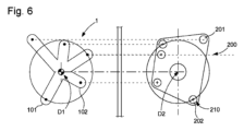
別の非限定的な例は、図6から図8によって示され、少なくとも1つの時計1000は、第1の内部可動体1を含み、第1の内部可動体1は、ここでは、不規則な外形を有し、この例では、角度が等しく分散していない、可変径方向幅広さの5つの腕部を含み、対応する調節工具200は、5つの磁石を含み、5つの磁石のうち3つは、同じ半径上にあり、他の2つは、他の半径値上にあり、これら5つの磁石のうち、4つの磁石は、第1の内部可動体に同じ極性を有する一方で、ただ1つの磁石は、反対の極性を有する。この調節工具は、第1の内部可動体に面するように構成される磁気ヨークを有する。
Another non-limiting example is shown by Figs. 6 to 8, where at least one
第1の内部可動体1と調節工具200との間の協働は、システムの改ざん防止を改善するため、形状及び特別な極性の組合せの両方に作用し得ることを理解されたい。同様に、第1の内部可動体1は、強磁性点領域及び/又は点磁石を含み得る。調節工具200は、任意の暗号化形状を有し得る。
It should be understood that the cooperation between the first internal
有利には、第1の内部可動体1は、外部の磁界による磁気の位置を決定するトルクを最小化するように、かなり小型の形状を有する。
Advantageously, the first internal
図8は、図6及び図7の第1の可動体と調節工具との間の協働(及びかなを破線で示した分離位置への後退)を示し、第1の軸D1及び第2の軸D2は位置合わせされている。第1の内部可動体1の強磁性領域及び調節工具200の磁石全体にわたる磁束のループは、閉ループによって、一方は実線で、他方は破線で図式化される。
Figure 8 shows the cooperation between the first movable body and the adjustment tool of Figures 6 and 7 (and the retraction to the separated position shown in dashed lines), with the first axis D1 and the second axis D2 aligned. The loop of magnetic flux through the ferromagnetic region of the first internal
機構、即ち十字体、可動体の内部要素の残留磁気は、ムーブメント又は時計の任意の他の機能を損なわないように十分に低いものでなければならない。 Residual magnetism in the internal elements of the mechanism, i.e. the cross, the moving body, must be low enough so as not to impair the movement or any other functions of the watch.
システムの実際のサイズは、時計の主な内部機能と比較して、小型のままでなければならない。 The actual size of the system must remain small compared to the main internal functions of the watch.
本発明による機構の操作は、顧客又は第3者による不本意な破壊といった問題を回避するため、製造業者が承認した製造工場又は専門店又はアフターサービスで留保される。したがって、十字体及び鍵は、従来の磁石による操作を防止するサイズで作製される。十字体の形状は、特殊で複雑であり、不透明層によって隠しても隠さなくてもよく、特殊な構成及び寸法の磁石を有する市場での発見が困難な特別なねじ回しと協働し得る。十字体は、高強度(数テスラ)の同種の外部磁界が加えられた際に適応可能であってはならず、可能な限りわずかにしか軸方向に移動しないはずである。 The operation of the mechanism according to the invention is reserved for the manufacturing factory or specialized shops or after-sales services approved by the manufacturer, to avoid problems such as unintentional destruction by the customer or third parties. Therefore, the cross and the key are made in a size that prevents operation with a conventional magnet. The shape of the cross is special and complex, may or may not be hidden by an opaque layer, and may cooperate with special screwdrivers that are difficult to find on the market, having magnets of special configuration and dimensions. The cross must be adaptable when subjected to the same kind of external magnetic field of high strength (several Teslas) and should move axially as little as possible.
このシステムは、従来のプッシュピース及び心棒に完全に代わり、現在のモデルよりかなり耐水性がある自動式時計又は他の時計の製造を可能にし得る。 This system completely replaces the traditional push piece and stem and could enable the production of automatic or other watches that are significantly more water resistant than current models.
Claims (21)
前記第1の内部可動体(1)は強磁性であり、
各前記調節工具(200)は、引力又は反発力によって前記第1の内部可動体(1)と相補的に協働するように構成される第1の磁気領域(210)を含むか、又は第2の磁気領域を含む、測時器組立体(2000)において、
前記第1の内部可動体(1)は、第1の軸(D1)回りに枢動移動可能であり、前記ケース(10)の要素(2)に締結される弾性戻し手段(5)に対して、一方の有効位置と、前記調節工具(200)がない他方の非有効位置との間で、前記第1の軸(D1)の方向に従って軸方向にも移動可能であり、
前記有効位置において、前記調節工具(200)は、前記時計(1000)に接して又は前記時計(1000)の近傍に配置され、前記第1の内部可動体(1)に固着されるか又は前記第1の内部可動体(1)によって形成される第1の駆動要素(3)と前記ケース(10)の内部の第2の内部可動体(7)との間の係合位置において、前記弾性戻し手段(5)若しくは前記要素(2)若しくは前記ケース(10)が含む進行終端面(6)に向かって前記第1の内部可動体(1)を引き付けるか又は押し戻し、前記非有効位置において、前記弾性戻し手段(5)は、前記第1の駆動要素(3)を前記第2の内部可動体(7)から分離させたままであり、前記弾性戻し手段は、前記弾性戻し手段自体で所望のトルクを供給し、調節を保証するように構成されることを特徴とする、測時器組立体(2000)。 A timepiece assembly (2000) comprising at least one timepiece (1000) and at least one adjustment tool (200), the at least one adjustment tool (200) being configured to enable the driving, without direct contact, of a first internal movable body (1) contained in each of the timepieces (1000) of the timepiece assembly (2000) through a case (10) contained in each of the timepieces (1000) in order to carry out adjustment and/or energy charging,
The first internal movable body (1) is ferromagnetic;
In the timepiece assembly (2000), each of the adjustment tools (200) comprises a first magnetic region (210) adapted to cooperate in a complementary manner with the first internal movable body (1) by means of an attractive or repulsive force, or comprises a second magnetic region,
said first internal movable body (1) is pivotally movable about a first axis (D1) and is also axially movable according to the direction of said first axis (D1) relative to elastic return means (5) fastened to an element (2) of said case (10) between one active position and another inactive position in the absence of said adjustment tool (200);
A timepiece assembly (2000), characterized in that in the active position, the adjustment tool (200) is placed in contact with or in the vicinity of the watch (1000) and, in an engagement position between a first driving element (3) fixed to or formed by the first internal movable body (1) and a second internal movable body (7) inside the case (10), attracts or pushes back the first internal movable body (1) towards a travel end face (6) comprised by the elastic return means (5) or the element (2) or the case (10), and in the non-active position, the elastic return means (5) keeps the first driving element (3) separated from the second internal movable body (7), and the elastic return means is configured to provide the desired torque by itself to ensure the adjustment.
Applications Claiming Priority (3)
| Application Number | Priority Date | Filing Date | Title |
|---|---|---|---|
| EP21204666.8 | 2021-10-26 | ||
| EP21204666 | 2021-10-26 | ||
| PCT/EP2022/066203 WO2023072437A1 (en) | 2021-10-26 | 2022-06-14 | Magnetic mechanism for controlling and/or driving through a watch case |
Publications (2)
| Publication Number | Publication Date |
|---|---|
| JP2024535932A JP2024535932A (en) | 2024-10-02 |
| JP7686882B2 true JP7686882B2 (en) | 2025-06-02 |
Family
ID=78413617
Family Applications (1)
| Application Number | Title | Priority Date | Filing Date |
|---|---|---|---|
| JP2024519932A Active JP7686882B2 (en) | 2021-10-26 | 2022-06-14 | Magnetic control and/or drive mechanism through the watch case |
Country Status (5)
| Country | Link |
|---|---|
| US (1) | US20250123593A1 (en) |
| EP (2) | EP4423577A1 (en) |
| JP (1) | JP7686882B2 (en) |
| CN (1) | CN118176463A (en) |
| WO (1) | WO2023072437A1 (en) |
Families Citing this family (1)
| Publication number | Priority date | Publication date | Assignee | Title |
|---|---|---|---|---|
| DE102024118362A1 (en) * | 2024-06-28 | 2025-12-31 | Horage SA | Clockwork with fine adjustment mechanism, setting device, clock |
Citations (2)
| Publication number | Priority date | Publication date | Assignee | Title |
|---|---|---|---|---|
| JP3674443B2 (en) | 1999-03-11 | 2005-07-20 | セイコーエプソン株式会社 | Electronic device, external adjustment device for electronic device, control method for electronic device, and control method for external adjustment device |
| JP2017219538A (en) | 2016-06-03 | 2017-12-14 | ザ・スウォッチ・グループ・リサーチ・アンド・ディベロップメント・リミテッド | Timer mechanism with a balance wheel with adjustable inertia |
Family Cites Families (4)
| Publication number | Priority date | Publication date | Assignee | Title |
|---|---|---|---|---|
| WO2014166719A2 (en) * | 2013-04-10 | 2014-10-16 | The Swatch Group Research And Development Ltd | Device for winding up a watch with self-winding mechanism |
| EP3163381B1 (en) * | 2015-10-26 | 2019-06-26 | The Swatch Group Research and Development Ltd. | Automatic winding of a watch |
| EP3474086A1 (en) * | 2017-10-23 | 2019-04-24 | Harry Winston SA | Case for electromechanical watch and assembly comprising same |
| EP3842876B1 (en) * | 2019-12-24 | 2025-02-19 | The Swatch Group Research and Development Ltd | Timepiece fitted with a mechanical movement and a device for correcting the time displayed |
-
2022
- 2022-06-14 EP EP22733114.7A patent/EP4423577A1/en active Pending
- 2022-06-14 US US18/691,959 patent/US20250123593A1/en active Pending
- 2022-06-14 CN CN202280072401.0A patent/CN118176463A/en active Pending
- 2022-06-14 EP EP22178995.1A patent/EP4174584A1/en not_active Withdrawn
- 2022-06-14 JP JP2024519932A patent/JP7686882B2/en active Active
- 2022-06-14 WO PCT/EP2022/066203 patent/WO2023072437A1/en not_active Ceased
Patent Citations (3)
| Publication number | Priority date | Publication date | Assignee | Title |
|---|---|---|---|---|
| JP3674443B2 (en) | 1999-03-11 | 2005-07-20 | セイコーエプソン株式会社 | Electronic device, external adjustment device for electronic device, control method for electronic device, and control method for external adjustment device |
| JP2017219538A (en) | 2016-06-03 | 2017-12-14 | ザ・スウォッチ・グループ・リサーチ・アンド・ディベロップメント・リミテッド | Timer mechanism with a balance wheel with adjustable inertia |
| EP3252545B1 (en) | 2016-06-03 | 2019-10-16 | The Swatch Group Research and Development Ltd. | Timepiece mechanism with balance wheel inertia adjustment |
Also Published As
| Publication number | Publication date |
|---|---|
| EP4423577A1 (en) | 2024-09-04 |
| CN118176463A (en) | 2024-06-11 |
| JP2024535932A (en) | 2024-10-02 |
| EP4174584A1 (en) | 2023-05-03 |
| US20250123593A1 (en) | 2025-04-17 |
| WO2023072437A1 (en) | 2023-05-04 |
| WO2023072437A8 (en) | 2024-05-30 |
Similar Documents
| Publication | Publication Date | Title |
|---|---|---|
| CN106062644B (en) | Movement of mechanical clock with magnetic escapement | |
| RU2666451C2 (en) | No-touch cylindrical trigger mechanism for watches | |
| US4066947A (en) | Stepping motor for electronic timepiece | |
| JP4558270B2 (en) | Watch case | |
| JP5171821B2 (en) | Electromechanical relief devices and watch parts using such devices | |
| EP1341063B1 (en) | Electronic timepiece with a date display function | |
| JP7686882B2 (en) | Magnetic control and/or drive mechanism through the watch case | |
| CN105103058A (en) | A continuous drilling fluid circulation unit and arrangement | |
| US9874855B2 (en) | Electronic clock movement comprising an analog display of several items of information | |
| US10037010B2 (en) | Timepiece comprising a device for switching a timekeeping mechanism | |
| KR101445455B1 (en) | Display device with a combination of display members | |
| HK40113373A (en) | Magnetic mechanism for controlling and/or driving through a watch case | |
| JP5236239B2 (en) | Timepiece having means for determining the angular position of an analog display of a timepiece | |
| JP5815043B2 (en) | Magnetic shield for watch balance spring | |
| US2977750A (en) | Indexing mechanism | |
| CN106919035B (en) | Contactless cylinder escapement | |
| JP2021032884A (en) | Self-winding watch | |
| HK1186255B (en) | Display device with a combination of display members | |
| US3298170A (en) | Dial train drive | |
| JPS62235591A (en) | Timepiece | |
| HK1230293A1 (en) | Mechanical timepiece movement with magnetic escapement | |
| CH719089A2 (en) | Magnetic control and/or drive mechanism through a watch case. | |
| JP2024122473A (en) | Mechanical Watches | |
| GB750004A (en) | Improvements in or relating to electric clocks | |
| HK40041320B (en) | Self-adjustable horological oscillator |
Legal Events
| Date | Code | Title | Description |
|---|---|---|---|
| A521 | Request for written amendment filed |
Free format text: JAPANESE INTERMEDIATE CODE: A523 Effective date: 20240401 |
|
| A621 | Written request for application examination |
Free format text: JAPANESE INTERMEDIATE CODE: A621 Effective date: 20240401 |
|
| A977 | Report on retrieval |
Free format text: JAPANESE INTERMEDIATE CODE: A971007 Effective date: 20250225 |
|
| A131 | Notification of reasons for refusal |
Free format text: JAPANESE INTERMEDIATE CODE: A131 Effective date: 20250304 |
|
| A521 | Request for written amendment filed |
Free format text: JAPANESE INTERMEDIATE CODE: A523 Effective date: 20250401 |
|
| TRDD | Decision of grant or rejection written | ||
| A01 | Written decision to grant a patent or to grant a registration (utility model) |
Free format text: JAPANESE INTERMEDIATE CODE: A01 Effective date: 20250507 |
|
| A61 | First payment of annual fees (during grant procedure) |
Free format text: JAPANESE INTERMEDIATE CODE: A61 Effective date: 20250521 |
|
| R150 | Certificate of patent or registration of utility model |
Ref document number: 7686882 Country of ref document: JP Free format text: JAPANESE INTERMEDIATE CODE: R150 |