JP7686881B2 - Slot Die Coater - Google Patents
Slot Die Coater Download PDFInfo
- Publication number
- JP7686881B2 JP7686881B2 JP2024518490A JP2024518490A JP7686881B2 JP 7686881 B2 JP7686881 B2 JP 7686881B2 JP 2024518490 A JP2024518490 A JP 2024518490A JP 2024518490 A JP2024518490 A JP 2024518490A JP 7686881 B2 JP7686881 B2 JP 7686881B2
- Authority
- JP
- Japan
- Prior art keywords
- upper plate
- groove
- die coater
- shim
- slot die
- Prior art date
- Legal status (The legal status is an assumption and is not a legal conclusion. Google has not performed a legal analysis and makes no representation as to the accuracy of the status listed.)
- Active
Links
Images


Classifications
-
- H—ELECTRICITY
- H01—ELECTRIC ELEMENTS
- H01M—PROCESSES OR MEANS, e.g. BATTERIES, FOR THE DIRECT CONVERSION OF CHEMICAL ENERGY INTO ELECTRICAL ENERGY
- H01M4/00—Electrodes
- H01M4/02—Electrodes composed of, or comprising, active material
- H01M4/04—Processes of manufacture in general
-
- B—PERFORMING OPERATIONS; TRANSPORTING
- B05—SPRAYING OR ATOMISING IN GENERAL; APPLYING FLUENT MATERIALS TO SURFACES, IN GENERAL
- B05C—APPARATUS FOR APPLYING FLUENT MATERIALS TO SURFACES, IN GENERAL
- B05C11/00—Component parts, details or accessories not specifically provided for in groups B05C1/00 - B05C9/00
- B05C11/10—Storage, supply or control of liquid or other fluent material; Recovery of excess liquid or other fluent material
-
- B—PERFORMING OPERATIONS; TRANSPORTING
- B05—SPRAYING OR ATOMISING IN GENERAL; APPLYING FLUENT MATERIALS TO SURFACES, IN GENERAL
- B05C—APPARATUS FOR APPLYING FLUENT MATERIALS TO SURFACES, IN GENERAL
- B05C5/00—Apparatus in which liquid or other fluent material is projected, poured or allowed to flow on to the surface of the work
- B05C5/02—Apparatus in which liquid or other fluent material is projected, poured or allowed to flow on to the surface of the work the liquid or other fluent material being discharged through an outlet orifice by pressure, e.g. from an outlet device in contact or almost in contact, with the work
- B05C5/0254—Coating heads with slot-shaped outlet
- B05C5/0262—Coating heads with slot-shaped outlet adjustable in width, i.e. having lips movable relative to each other in order to modify the slot width, e.g. to close it
-
- B—PERFORMING OPERATIONS; TRANSPORTING
- B05—SPRAYING OR ATOMISING IN GENERAL; APPLYING FLUENT MATERIALS TO SURFACES, IN GENERAL
- B05C—APPARATUS FOR APPLYING FLUENT MATERIALS TO SURFACES, IN GENERAL
- B05C5/00—Apparatus in which liquid or other fluent material is projected, poured or allowed to flow on to the surface of the work
- B05C5/02—Apparatus in which liquid or other fluent material is projected, poured or allowed to flow on to the surface of the work the liquid or other fluent material being discharged through an outlet orifice by pressure, e.g. from an outlet device in contact or almost in contact, with the work
- B05C5/0254—Coating heads with slot-shaped outlet
- B05C5/0266—Coating heads with slot-shaped outlet adjustable in length, e.g. for coating webs of different width
-
- H—ELECTRICITY
- H01—ELECTRIC ELEMENTS
- H01M—PROCESSES OR MEANS, e.g. BATTERIES, FOR THE DIRECT CONVERSION OF CHEMICAL ENERGY INTO ELECTRICAL ENERGY
- H01M4/00—Electrodes
- H01M4/02—Electrodes composed of, or comprising, active material
- H01M4/04—Processes of manufacture in general
- H01M4/0402—Methods of deposition of the material
- H01M4/0411—Methods of deposition of the material by extrusion
Landscapes
- Engineering & Computer Science (AREA)
- Manufacturing & Machinery (AREA)
- Chemical & Material Sciences (AREA)
- Chemical Kinetics & Catalysis (AREA)
- Electrochemistry (AREA)
- General Chemical & Material Sciences (AREA)
- Coating Apparatus (AREA)
Description
本発明は、スロットダイコーターに関し、特に、内部圧力によるダイブロックの歪みを改善したスロットダイコーターに関する。 The present invention relates to a slot die coater, and in particular to a slot die coater that improves the distortion of the die block caused by internal pressure.
本出願は、2022年7月29日付け出願の韓国特許出願第10-2022-0094861号及び2023年5月15日付け出願の韓国特許出願第10-2023-0062678号に基づく優先権を主張し、当該出願の明細書及び図面に開示された内容は、すべて本出願に組み込まれる。 This application claims priority to Korean Patent Application No. 10-2022-0094861, filed on July 29, 2022, and Korean Patent Application No. 10-2023-0062678, filed on May 15, 2023, the entire contents of which are incorporated herein by reference in their entirety in the specification and drawings.
最近のモバイル機器に対する技術の開発と需要の増加には目を見張るものがあり、これに伴い、エネルギー源としての二次電池へのニーズが急激に伸びている。このような二次電池は、発電要素である電極組立体を必須的に含んでいる。電極組立体は、正極、セパレーター及び負極が少なくとも1回以上積層された形態を有し、正極と負極は、それぞれアルミニウム箔と銅箔からなる集電体に正極活物質スラリーと負極活物質スラリーが塗布及び乾燥されて製造される。このような二次電池は、一般に、正極活物質として、層状結晶構造のリチウム含有コバルト酸化物(LiCoO2)と、層状結晶構造のLiMnO2、スピネル結晶構造のLiMn2O4などのリチウム含有マンガン酸化物と、リチウム含有ニッケル酸化物(LiNiO2)を用いる。また、負極活物質として炭素系の物質が主として用いられ、最近では、高エネルギーリチウム二次電池へのニーズの増加により、炭素系物質よりも10倍以上の有効容量を有するシリコン系物質、シリコン酸化物系物質との混合使用が考えられている。二次電池の充放電特性を均一にするためには、このような正極活物質スラリー及び負極活物質スラリーが集電体に一様にコートされていなければならず、従来よりスロットダイコーターを利用している。
Recent technological developments and increasing demands for mobile devices have been remarkable, and as a result, the need for secondary batteries as energy sources has been growing rapidly. Such secondary batteries essentially include an electrode assembly, which is a power generating element. The electrode assembly has a form in which a positive electrode, a separator, and a negative electrode are laminated at least once, and the positive electrode and the negative electrode are manufactured by applying a positive electrode active material slurry and a negative electrode active material slurry to current collectors made of aluminum foil and copper foil, respectively, and drying them. Such secondary batteries generally use lithium-containing cobalt oxide (LiCoO 2 ) with a layered crystal structure, lithium-containing manganese oxide such as LiMnO 2 with a layered crystal structure and LiMn 2 O 4 with a spinel crystal structure, and lithium-containing nickel oxide (LiNiO 2 ) as the positive electrode active material. Carbonaceous materials are mainly used as negative electrode active materials, and recently, due to the increasing need for high-energy lithium secondary batteries, the mixed use of silicon-based materials and silicon oxide-based materials, which have
図1は、従来のスロットダイコーターを示す斜視図であり、図2は、従来のスロットダイコーターの分解斜視図である。 Figure 1 is a perspective view showing a conventional slot die coater, and Figure 2 is an exploded perspective view of a conventional slot die coater.
図1及び図2を参照すると、スロットダイコーター1を用いた電極の製造方法においては、コーティングロール(図示せず)により搬送される集電体(図示せず)の上にスロットダイコーター1から吐き出された活物質スラリーを塗布することになる。スロットダイコーター1から吐き出された活物質スラリーは、集電体の片面に広く塗布されて活物質層を形成する。
Referring to Figures 1 and 2, in the method of manufacturing an electrode using a
スロットダイコーター1は、2つのダイブロック10、20を含み、2つのダイブロック10、20の間にスロット30を形成したものである。2つのダイブロック10、20は、結合ボルト70により互いに締め合わせられている。スロット30と連通している吐出口40を介して活物質スラリーを吐き出して活物質層を形成することができる。スロットダイコーター1は、バーコーティング又はコンマコーティングに比べて高速にて塗布可能であるというメリットがあることから、高い生産性の観点からみて頻繁に適用されている。
The slot die
集電体の上にコートされる活物質層のコーティング幅は、スロット30の幅Wにより決定される。コーティング幅の変更が必要である場合、マニホールド50の内部空間及びスロット30の幅Wを決定するシム60を変更して様々なコーティング幅を実現することができる。
The coating width of the active material layer coated on the current collector is determined by the width W of the
図1に例として挙げたスロットダイコーター1は、活物質スラリーが重力の反対の方向に吐き出される垂直ダイタイプである。垂直方向にスロットダイコーター1を構成してコートする場合、ダイブロック10、20の内部圧力によりダイブロック10、20同士が広がるという現象がある。2つのダイブロック10、20の間にシム60を用いて未コーティング部(集電体にコートされていない部分、無地部)を実現するときに、2つのダイブロック10、20同士が広がって活物質スラリーが流れ込むと、未コーティング部に断続的に活物質スラリーが付いて表面不良が起こるという問題が生じてしまう。
The
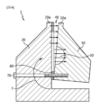
図3は、従来のスロットダイコーターの当初の結合状態を示す断面図であり、図1におけるII-II’矢視断面に相当する。図4は、従来のスロットダイコーターにおけるダイの内部圧力による歪みを示す断面図である。図5は、従来のスロットダイコーターにおいて、ダイの内部にスラリーが入り込んで集電体の無地部に表面不良が生じる問題を示す図である。 Figure 3 is a cross-sectional view showing the initial bonding state of a conventional slot die coater, and corresponds to the cross-section taken along the line II-II' in Figure 1. Figure 4 is a cross-sectional view showing distortion caused by internal pressure of the die in a conventional slot die coater. Figure 5 is a diagram showing the problem of slurry getting inside the die in a conventional slot die coater, causing surface defects in the uncoated areas of the current collector.
図3中、2つのダイブロック10、20は、結合ボルト70により互いに締め合わせられている。ダイブロック10、20の内部圧力が増加するとき、図4に示すように、結合ボルト70を基点(基準点)として内部圧力によるトルクTが生じる。それにより、最も遠い部分が最も大きな力を受けてダイブロック10、20の先端部であるダイリップ10a、20aの部分が広がってしまう。そうすると、シム60における活物質スラリーを塞いで吐き出しができないようにすべき部分にまで活物質スラリーが入り込んでしまう。
In FIG. 3, the two die
これにより、図5に示すように、活物質スラリー75があってはならないダイブロック10、20の内部にまで活物質スラリー75が入り込んで、集電体80の無地部80aに表面不良90が生じる。表面不良90がないことが前提となってこそ、MD方向に形成される無地部80aに沿ってスリッティング(slitting)してそれぞれの活物質層80bに電極を形成するときにスリッティング不良を生ぜず、万が一でも無地部80aに残っている表面不良90により二次電池の製造の後に電極の断線が生じない。
As a result, as shown in FIG. 5, the active material slurry 75 penetrates into the
本発明は、上述した事情に鑑みて案出されたものであって、本発明の目的は、ダイの内圧の増加による未コーティング部への活物質スラリーの吐き出しを防ぐようにすることである。 The present invention was devised in consideration of the above circumstances, and the object of the present invention is to prevent the active material slurry from being ejected into the uncoated area due to an increase in the internal pressure of the die.
これにより、本発明が解決しようとする課題は、内部圧力によるダイブロックの歪みを改善したスロットダイコーターを提供することである。 The problem that this invention aims to solve is to provide a slot die coater that improves the distortion of the die block caused by internal pressure.
但し、本発明が解決しようとする技術的課題は、上述した課題に何ら制限されるものではなく、言及されていない他の課題は、下記に記載されている発明の説明から当業者にとって明らかに理解できるものである。 However, the technical problems that the present invention aims to solve are in no way limited to those described above, and other problems not mentioned will be clearly understood by those skilled in the art from the description of the invention provided below.
上述した課題を解決するための本発明のスロットダイコーターは、互いに組み合わせられて吐出口を形成する上板及び下板と、前記下板と前記上板との間に介在して前記吐出口と連通するスロットを形成するシムと、を含み、前記上板は、前記スロットの上側に前記シムと平行に前記上板の内部に湾入している溝を備え、前記溝に差し込まれて前記シムを押し付けるテーパーブロック及び押圧ボルトをさらに含む。 The slot die coater of the present invention, which solves the above-mentioned problems, includes an upper plate and a lower plate that are combined with each other to form an outlet, and a shim that is interposed between the lower plate and the upper plate to form a slot that communicates with the outlet, and the upper plate has a groove that is parallel to the shim and extends into the upper plate above the slot, and further includes a taper block and a pressure bolt that are inserted into the groove to press the shim.
前記溝は、前記溝の内側に向かって進むにつれて高さが次第に低くなり、それに前記テーパーブロックの傾斜が合わせられたものであり得る。 The groove may have a height that gradually decreases toward the inside of the groove, with the inclination of the tapered block being adjusted accordingly.
前記押圧ボルトは、前記溝の前側から前記テーパーブロックを貫通して前記上板に締結され得る。 The pressure bolt can be fastened to the upper plate by passing through the tapered block from the front side of the groove.
前記溝は、前記上板の前面から背面に向かって湾入しており、前記押圧ボルトは、前記上板の前面において前記テーパーブロックに締結され得る。 The groove is recessed from the front to the back of the upper plate, and the pressure bolt can be fastened to the tapered block at the front of the upper plate.
前記テーパーブロックは、前記押圧ボルトに締結されて前記吐出口の吐出方向と平行な方向において前後に動き、前記溝とテーパーブロックとの高さ差による力を生じさせて前記シムを押し付け得る。 The taper block is fastened to the pressure bolt and moves back and forth in a direction parallel to the discharge direction of the discharge port, generating a force due to the height difference between the groove and the taper block, which can press the shim.
前記シムは、複数の開放部を含むようにベース部に垂直に接続されて前記吐出口側に延びる複数の延在部を含み、前記テーパーブロックの横長は、前記延在部の横長よりも大きくなく、前記テーパーブロックは、前記延在部に対応する位置において前記溝に差し込まれ得る。 The shim includes multiple extensions that are connected perpendicularly to the base to include multiple openings and extend toward the outlet, the horizontal length of the taper block is not greater than the horizontal length of the extensions, and the taper block can be inserted into the groove at a position corresponding to the extensions.
前記複数の延在部のうちの端(サイド)にある延在部を除いた延在部に対応する位置に前記テーパーブロックが配備され得る。 The taper block may be disposed at a position corresponding to one of the multiple extensions, excluding the extensions at the ends (sides).
前記スロットダイコーターは、前記下板にマニホールドをさらに含み、前記マニホールドの前端から前記吐出口までの領域であるランドの長さよりも前記テーパーブロックの長さの方が短いものであり得る。 The slot die coater may further include a manifold on the lower plate, and the length of the taper block may be shorter than the length of a land, which is the region from the front end of the manifold to the discharge port.
本発明の一側面によれば、前記溝は、前記吐出口側に形成される。 According to one aspect of the present invention, the groove is formed on the discharge port side.
前記溝と位置合わせされる位置に前記押圧ボルトが締結されるボルト溝が形成され得る。 A bolt groove into which the pressure bolt is fastened can be formed at a position aligned with the groove.
前記テーパーブロックに前記ボルト溝と位置合わせされて前記押圧ボルトが貫通可能なように孔が形成され得る。 A hole may be formed in the tapered block that is aligned with the bolt groove so that the pressure bolt can pass through.
本発明の他の側面によれば、前記押圧ボルトは、前記上板の背面から前記上板を貫通して前記テーパーブロックに締結される。 According to another aspect of the invention, the pressure bolt penetrates the upper plate from the rear surface thereof and is fastened to the taper block.
前記スロットダイコーターは、前記押圧ボルトが差し込み可能なように前記上板の背面に幅方向に長孔を含む。 The slot die coater includes a long hole in the width direction on the back surface of the upper plate so that the pressure bolt can be inserted.
前記押圧ボルトとテーパーブロックが前記幅方向に沿って複数配備され得る。 The pressure bolts and taper blocks may be arranged in multiple locations along the width direction.
前記テーパーブロック内に前記押圧ボルトが締結可能なねじ線が形成され得る。 A thread line may be formed within the taper block to which the pressure bolt can be fastened.
前記長孔は、前記上板の背面から前面に向かって形成され、前記溝は、前記上板の前面から背面に向かって形成され、前記長孔は、前記溝と位置合わせされる位置に形成され得る。 The long hole may be formed from the rear surface of the upper plate toward the front surface, the groove may be formed from the front surface of the upper plate toward the rear surface, and the long hole may be formed at a position that is aligned with the groove.
前記下板にコーティング液を収容するマニホールドが配備され、前記マニホールドが前記スロットと連通し得る。 A manifold containing a coating liquid may be provided on the lower plate, and the manifold may be in communication with the slot.
前記スロットダイコーターは、前記吐出口を介して前記コーティング液を基材の上に吐き出して塗布し、前記シムは、前記基材の上に塗布されるコーティング層のコーティング幅を決定するように一領域が間隔を空けて断続的に切り欠かれて複数の開放部を備え得る。 The slot die coater applies the coating liquid by spitting it onto the substrate through the discharge port, and the shim may have a plurality of openings, with one area intermittently cut out at intervals to determine the coating width of the coating layer applied onto the substrate.
前記テーパーブロックと押圧ボルトは、前記開放部に影響を与えずに前記シムを押し付けて前記上板と下板との広がりを防ぎ得る。 The taper block and pressure bolt can press the shim without affecting the opening, preventing the upper and lower plates from spreading apart.
本発明によれば、スロットダイコーターにおける上板の構造を変更し、テーパーブロック及び押圧ボルトをさらに含んで、スロットダイの内部圧力の増加による未コーティング部への活物質スラリーの吐き出しを防ぐことができる。 According to the present invention, the structure of the upper plate in the slot die coater is modified to further include a taper block and a pressure bolt, which can prevent the active material slurry from being ejected into the uncoated area due to an increase in the internal pressure of the slot die.
これにより、未コーティング部への活物質スラリーの吐き出しを防いで、電極の形成時の表面不良を改善することができる。特に、ストライプパターン状の活物質層を形成するときに無地部にパターン不良を生じさせることなく、安定的に活物質層を形成することができる。 This prevents the active material slurry from spilling onto uncoated areas, improving surface defects during electrode formation. In particular, when forming a striped pattern of active material layers, it is possible to stably form the active material layers without causing pattern defects in the plain areas.
このような本発明のスロットダイコーターを用いると、所望の厚さ及び形状に均一にコーティング層、特に、電極活物質層を形成することができる。 By using the slot die coater of the present invention, it is possible to form a coating layer, particularly an electrode active material layer, uniformly to the desired thickness and shape.
本明細書に添付される次の図面は、本発明の望ましい実施形態を例示するものであり、発明の内容とともに本発明の技術的な思想をさらに理解させる役割のためのものであるため、本発明は図面に記載された事項だけに限定されて解釈されるものではない。 The following drawings attached to this specification are intended to illustrate preferred embodiments of the present invention and serve to facilitate a better understanding of the technical concepts of the present invention as well as the contents of the invention. Therefore, the present invention should not be interpreted as being limited to only the matters depicted in the drawings.
以下、添付された図面を参照して本発明の望ましい実施形態を詳しく説明する。これに先立ち、本明細書及び特許請求の範囲に使われた用語や単語は通常的や辞書的な意味に限定して解釈されるものではなく、発明者自らは発明を最善の方法で説明するために用語の概念を適切に定義できるという原則に則して本発明の技術的な思想に応ずる意味及び概念で解釈されるものである。したがって、本明細書に記載された実施形態及び図面に示された構成は、本発明の最も好ましい一実施形態に過ぎず、本発明の技術的な思想のすべてを表すものではないため、本出願の時点においてこれらに代替できる多様な均等物及び変形例があり得ることを理解されたい。 Hereinafter, a preferred embodiment of the present invention will be described in detail with reference to the attached drawings. Prior to this, the terms and words used in this specification and claims are not to be interpreted as being limited to their ordinary or dictionary meanings, but are to be interpreted as being in accordance with the meaning and concept of the technical idea of the present invention, in accordance with the principle that the inventor himself can appropriately define the concept of the term in order to best describe the invention. Therefore, it should be understood that the embodiment described in this specification and the configuration shown in the drawings are merely the most preferred embodiment of the present invention, and do not represent the entire technical idea of the present invention, and therefore there may be various equivalents and modifications that can be substituted therefor at the time of this application.
同じ図面符号は、同じ構成要素を指し示す。また、図中、構成要素の厚さ、比率、及び寸法は、技術的内容の効果的な説明のために誇張されたものである。 The same reference numerals refer to the same components. Also, in the drawings, the thickness, ratio, and dimensions of the components are exaggerated for the purpose of effectively explaining the technical content.
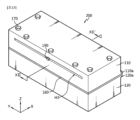
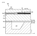
図6は、本発明の一実施形態によるスロットダイコーターを示す斜視図である。図7は、図6に示すスロットダイコーターの幅方向に垂直な断面図であって、図6のVII-VII’矢視断面に相当し、吐出口の吐出方向と平行な断面を示す。図8は、図7に示すスロットダイコーターの変形例の図である。図9は、図6に示すスロットダイコーターの幅方向に垂直な他の断面図であって、図6のVIII-VIII’矢視断面に相当し、図6と同様に、吐出口の吐出方向と平行な断面を示す。図10は、図7の部分拡大図であり、図11は、図6に示すスロットダイコーターの正面図である。 Figure 6 is a perspective view showing a slot die coater according to one embodiment of the present invention. Figure 7 is a cross-sectional view perpendicular to the width direction of the slot die coater shown in Figure 6, which corresponds to the cross-sectional view taken along the line VII-VII' in Figure 6 and shows a cross-section parallel to the discharge direction of the discharge port. Figure 8 is a view of a modified example of the slot die coater shown in Figure 7. Figure 9 is another cross-sectional view perpendicular to the width direction of the slot die coater shown in Figure 6, which corresponds to the cross-sectional view taken along the line VIII-VIII' in Figure 6 and shows a cross-section parallel to the discharge direction of the discharge port, similar to Figure 6. Figure 10 is a partially enlarged view of Figure 7, and Figure 11 is a front view of the slot die coater shown in Figure 6.
先の図1に示されているように、既存のスロットダイコーター1が2つのダイブロック10、20とシム60とから構成されているのに対し、図6から図11に示されているように、本発明のスロットダイコーター100においては、上板110(構造の変更)と、下板120と、シム160と、テーパーブロック180(taper block)及び押圧ボルト190を含んで構成されている。
As shown in FIG. 1, the existing slot die
本発明のスロットダイコーター100は、スロット130を備え、スロット130を介して基材の上にコーティング液をコートする装置である。以下で説明する「基材」は集電体であり、「コーティング液」は活物質スラリーである。但し、本発明の権利範囲がこれに必ずしも制限されるとは限らない。例えば、基材は、セパレーターを構成する多孔性支持体であり、コーティング液は有機物であり得る。すなわち、薄膜コーティングが求められる場合であれば、基材とコーティング液はいなかるものであっても構わない。本明細書中において、「前」は吐出口が向く方向(X軸方向)を示し、「後」はその反対の方向を指すことがある。「左/右」は、吐出口が向く方向に垂直な方向であって、スロットの幅方向(Y軸方向)を指すことがある。
The slot die
図6から図11を参照すると、本発明の一実施形態によるスロットダイコーター100は、コーティング液を吐き出すためのスロット130を備えるスロットダイコーターであって、上板110と下板120を含む。例えば、吐出口140の方向であるX軸方向が重力の反対の方向となるようにスロットダイコーター100を設置すれば、意図の通りに、コーティング液を重力の反対の方向に吐き出す垂直ダイとして実現することができる。
Referring to Figures 6 to 11, the
上板110と下板120は、互いに組み合わせられてスロット130と連通する吐出口140を形成する。上板110と下板120は、固定ボルト170により組み合わせられ得る。
The
上板110は、下板120との間にスロット130を形成する。シム160(shim)が下板120と上板110との間に介在して吐出口140と連通するスロット130を形成することになる。
The
上板110と下板120は、吐出口140が向く前方であるX軸方向への長さよりも、それに垂直なY軸方向への幅の方が長い長方形の部材である。シム160は、上板110と下板120との接面に面接し、上板110と下板120とを互いに締め合わせる固定ボルト170により上板110と下板120との間に組み付けられ得る。
The
スロット130は、上板110と下板120とが互いに対面するところの間に形成される。ここにシム160が介在してこれらの間に隙間が設けられることにより、コーティング液が流動可能な通路に相当するスロット130が形成されるのである。シム160の厚さは、スロット130の上下の幅(Z軸方向、スロットギャップ)を決定する。
The
上板110と下板120のほとんどの面は略垂直になるように作製されたものが使用可能である。このような上板110と下板120においては、面と面とがなす縁が直角に形成されるので、断面視で直角部が存在し、垂直又は水平面を基準となる面とすることができるので、その作製や取り扱いが行い易く、しかも、精度が保証される。また、上板110と下板120とを組み合わせるときに対面する部分が高い面接触度をもって互いに支持されることが可能であるので、締結固定及び保持が非常に良好に行われる。のみならず、上板110と下板120とが組み合わせられた状態は全体として略直方体の形状を有し、コーティング液が吐き出される前方部のみが基材に向かって斜めになるような形状を呈し得る。
Most of the surfaces of the
上板110と下板120は、例えば、SUS(ステンレス鋼)材である。SUS420J2、SUS630、SUS440C、SUS304、SUS316Lなどの加工し易い材料が利用可能である。SUSは加工し易く、安価であり、耐食性が高く、低いコストにて所望の形状に作製することができるというメリットがある。
The
一般に、SUS組立体の結合面からは液漏れが生じ易いため、ゴムリングやその他の軟性材質の材料を構成物の間に位置付けてシールすることで液漏れを抑える。しかしながら、このようなシール方式は、均一な組立形態(例えば、10μm未満の組立偏差)を制御するのに不向きであるため、スロットダイコーター100には適用し難い。このため、スロットダイコーター100は、非常に高い精度(真直度、平坦度±5μm)で加工された上板110と下板120とを固定ボルト170により互いに締め合わせて組み合わせる。液漏れを防がなければならないため、固定ボルト170の締結は、約200~350Nの高圧にすることが好ましい。
Generally, liquid leakage is likely to occur from the joining surfaces of SUS assemblies, so rubber rings or other soft materials are positioned between the components to seal and prevent liquid leakage. However, this type of sealing method is difficult to apply to the
上板110は、スロット130の上側に、シム160と平行に上板110の内部に湾入している溝H1を備える。テーパーブロック180及び押圧ボルト190は、溝H1に差し込まれてシム160を押し付けることになる。
The
このように、本発明においては、上板110にテーパーブロック180が差し込み可能な溝H1が加工される。溝H1は、吐出口140側に形成される。換言すれば、溝H1は、上板110の前面に形成される。溝H1は、上板110の前面から背面に向かって、すなわち、上板110の内部に湾入している。
In this way, in the present invention, a groove H1 into which the
溝H1は、上板110の一部が陥凹しているもの、もしくは上板110を切削加工したものに相当し得る。溝H1は、所要の分だけ、しかし、できる限り最小のサイズにして上板110の機械的な剛性を損なわないようにすることが好ましい。図示のごとく、溝H1は、幅方向に長尺な形状であり得るが、必ずしもその限りではない。
Groove H1 may correspond to a recess in a portion of
そして、図7及び図8を参照すると、上板110に固定及び押圧のためのボルト溝H2を加工する。ボルト溝H2は、溝H1と位置合わせされる位置に押圧ボルト190が締結されるように形成され得る。押圧ボルト190は、上板110の前面においてテーパーブロック180に締結される。押圧ボルト190の操作は、上板110の前面において行われる。
Referring to FIG. 7 and FIG. 8, a bolt groove H2 for fixing and pressing is machined on the
また、テーパーブロック180及び押圧ボルト190は、左右の両端(サイド)を除いたシム160の部位にシム160を押し当て可能なように位置する。押圧ボルト190は、溝H1内にテーパーブロック180の位置を固定しながら、これと同時にテーパーブロック180及び溝H1の高さ差に伴う押し付け力を生じさせてシム160を押し当て可能にする役割を果たす。
The
押圧ボルト190の締め付けられる度合いをもってテーパーブロック180の位置を調整して押し付け力を調整し得る。テーパーブロック180は、押圧ボルト190により位置が可変となる。特に、テーパーブロック180は、押圧ボルト190に締結されて吐出口の吐出方向と平行な方向において前後に可動となる。テーパーブロック180には、ボルト溝H2と位置合わせされて押圧ボルト190が貫通可能なように孔Oが形成されている。
The pressing force can be adjusted by adjusting the position of the
図7中、ボルト溝H2は、押圧ボルト190の直径と略同一の大きさに形成されており、押圧ボルト190が締結可能なようにねじ線加工が施されている。ボルト溝H2は、溝H1よりもさらに内側にまで形成されており、押圧ボルト190の端部を締結可能なようになっている。押圧ボルト190は、端部にまでねじ線が形成されている。
In FIG. 7, the bolt groove H2 is formed to be approximately the same size as the diameter of the
図8は、他の例であり、押圧ボルト190は、一定の長さまでしかねじ線が形成されておらず、端部は無地である。このような押圧ボルト190の端部がボルト溝H2内において空回りしないように、ボルト溝H2に横切って差し込まれるU字状の通孔付き掛け金具がさらに含まれ得る。掛け金具の後端にはボルト溝H2が広く形成されていて、押圧ボルト190の端部の応力を解消することができる。
Figure 8 shows another example, where the
下板120には、コーティング液を収容するマニホールド150(manifold)が配備され得る。マニホールド150は、所定の形状と深さを有し得る。図示はしないが、このようなマニホールド150は、外部に配設されたコーティング液供給チャンバー(図示せず)と供給管により接続されてコーティング液の供給を受ける。マニホールド150内にコーティング液が満杯に充填されると、前記コーティング液の流れがスロット130に沿って誘導され、吐出口140を介して外部に吐き出されることになる。
A manifold 150 for containing the coating liquid may be provided on the
マニホールド150は、活物質スラリーのようなコーティング液を集電体のような基材の上に均一に供給/吐き出すために形成されているものである。マニホールド150は、上板110に配備されることもある。
The manifold 150 is formed to uniformly supply/discharge a coating liquid such as an active material slurry onto a substrate such as a current collector. The manifold 150 may also be provided on the
図中、参照符号110aと120aは、上板110と下板120の先端部であるダイリップを指す。
In the figure,
図7及び図10に詳しく示されているように、テーパーブロック180が差し込まれ得る溝H1は、溝H1の内側に向かって進むにつれて、すなわち、上板110の前面から背面に向かって進むにつれて高さhが次第に低くなる。そして、テーパーブロック180の傾斜がそれに合わせられ得る。換言すれば、溝H1は、上板110の内部に進んでいくにつれて高さhが次第に低くなるように形成されており、テーパーブロック180もまたそのように形成されている可能性がある。
As shown in detail in Figures 7 and 10, the groove H1 into which the
テーパーブロック180は、このような溝H1内において押圧ボルト190により前後方向に可動となるように設計されている。例えば、テーパーブロック180は、図示のごとく、下面が平らであり、上面が傾斜したものであり得る。これに合わせて、溝H1もまた下面が平らであり、上面が傾斜するように形成されて溝H1の内側に向かって進むにつれて高さhが次第に低くなるように形成されている可能性がある。
The
溝H1の下面を平らにすることにより、溝H1をシム160と平行にすることができる。テーパーブロック180の下面を平らにすることにより、一様な力がシム160の向きに加えられるようにすることができる。溝H1とテーパーブロック180の上面と下面をいずれも傾斜させても、上板110の前面から背面に向かって進むにつれて高さhが次第に低くなるようにすることができるものの、下面を平らにすることにより、加工作業や操作の基準面になるようにし、溝H1とテーパーブロック180を非常に高い精度(真直度、平坦度±5μm)で加工することができる。
By flattening the bottom surface of groove H1, groove H1 can be made parallel to shim 160. By flattening the bottom surface of
押圧ボルト190は、溝H1の前側からテーパーブロック180を貫通して上板110に締結され得る。すなわち、押圧ボルト190の操作は、上板110の前面において行われ得る。
The
テーパーブロック180の押圧ボルト190を締め付けば締め付けるほど、すなわち、図10中の小さな矢印の向きにテーパーブロック180が溝H1の内側に向かって動けば動くほど、当該地点に垂直方向に太い矢印にて示した力Fが加えられる。溝H1が内側に向かって進むにつれて高さhが次第に低くなるが、ここにテーパーブロック180を押し込めば押し込むほど、溝H1とテーパーブロック180との高さ差が生じ、狭い隙間に大きな物体を差し込むことに相当して四方に押し出そうとする力を生じさせる。このように、テーパーブロック180が四方に押して溝H1を四方に広げようとする力の中でも、特にシム160を押圧する方向への力Fを利用する。この力Fが上板110、シム160及び下板120の間を締め付けることになる。テーパーブロック180の下面の面積BAによって一様にシム160を締め付けることができる。コーティング液の吐き出しによりスロットダイコーター100の内部圧力が増加する状況下でも、テーパーブロック180がシム160を押し付ける力Fが働くので、上板110と下板120の歪みを防いで未コーティング部への活物質スラリーの吐き出しを防ぐことができる。
The more the
図7と図8を参照すると、テーパーブロック180の長さD1は、ランド120b(land)の長さLよりも短い必要がある。ランド120bは、マニホールド150の前端から吐出口140までの領域を指す。テーパーブロック180の長さD1がランド120bの長さLよりも長い場合には、マニホールド150の部分に影響を及ぼす虞がある。
Referring to Figures 7 and 8, the length D1 of the
また、図11を参照すると、テーパーブロック180の横長D2は、幅方向にシム160の長さSよりも大きくない必要がある。テーパーブロック180の横長D2がシム160の長さSよりも大きい場合、スロットギャップGに影響を及ぼす虞がある。このように、テーパーブロック180は、上板110においてもセンターの部分に働き、テーパーブロック180が幅方向に吐出口140に影響を及ぼす程度に過剰に長尺状に繋がってはいない。テーパーブロック180は、その下のシム160の部分にのみ働くようになっている。テーパーブロック180は、スロットギャップGを変化させることはない。
Referring to FIG. 11, the horizontal length D2 of the
図12は、図6に示すスロットダイコーターに含まれ得るシムの一例を示す斜視図である。 Figure 12 is a perspective view showing an example of a shim that can be included in the slot die coater shown in Figure 6.
図6及び図12を結び付けて参照すると、シム160は、吐出口140が形成される領域を除いては、上板110と下板120との間の隙間にコーティング液が漏れ出ないようにするガスケット(gasket)としての機能を兼ねるため、密封性を有する材質からなることが好ましい。シム160は、例えば、プラスチック製または金属製のものであり得るが、本発明がこれに制限されることはない。シム160は、例えば、テフロン(登録商標)、ポリエステルなどの樹脂シート、または銅、アルミニウムなどの金属シートであり得る。
6 and 12 together, the
シム160は、継ぎ目のない一体形の構造物であり得る。シム160は、上面が平らであり、下面もまた平らであり得る。すなわち、シート状の部材であり得る。
The
シム160は、上板110と下板120との対向面の周縁領域のうちの一側を除いた残りの部分に介在し得る。このため、コーティング液が外部に吐き出し可能な吐出口140は、ダイリップ110a、120aの間に形成される。吐出口140は、ダイリップ110a、120a同士が隔たり合うことにより形成された個所であるといえ、スロット130の終端が吐出口140となる。シム160は、基材の上に塗布されるコーティング層のコーティング幅を決定するように一領域が間隔を空けて断続的に切り欠かれて複数の開放部160aを備える。開放部160aはスロット130を限定し、スロット130の末端が吐出口140となる。開放部160aの数が単一であれば、単一のコーティング層を、図示のごとく、開放部160aの数が2つであれば、2つのコーティング層をY軸方向に沿って左右に並ぶように形成し得る。
The
例えば、シム160は、複数の開放部160aを含むようにベース部161に垂直に接続されて吐出口140側に延びる複数の延在部162を含み得る。基材の上にコーティング幅がbである活物質層を複数形成し、各活物質層の両脇には無地部が形成されるようにするために、シム160の開放部160aの幅をbに設計する。図12に示すようなシム160を適用するとき、基材の上にストライプ(stripe)パターン状のコーティング層が形成される。
For example, the
図11を参照して説明した通り、複数の延在部162のうちの端(サイド)にある延在部を除いた延在部162に対応する位置にテーパーブロック180が配備され得る。特に、テーパーブロック180の横長D2は、シム160の延在部162、特に、センターに位置している延在部162の長さSよりも大きくなく、テーパーブロック180は、このような延在部162に対応する位置において溝H1に差し込まれ、当該部位の延在部162を押し付け得る。また、テーパーブロック180の長さD1を調整して、テーパーブロック180は、マニホールド150に影響を及ぼすことなく、ランド120bの部位を押圧する方式である。テーパーブロック180は、延在部162に対応する位置において延在部162の両側の開放部160aまでは侵さないようなサイズを有しているので、テーパーブロック180と押圧ボルト190は、開放部160aに影響を及ぼさず、シム160を押し付けることができる。シム160を押し付けて上板110と下板120との広がりを防ぐことができる。
As described with reference to FIG. 11, the
テーパーブロック180の下方にシム160が位置する。シム160が上板110を受け止めていることから、テーパーブロック180を操作しても開放部160aに影響を及ぼさず、それにより、スロットギャップGの歪みがない。すなわち、テーパーブロック180を操作しても吐出口140を介したコーティング液の流量の変動がない。本発明は、スロットギャップGの変化を目指すものではなく、スロットギャップGに影響を及ぼさない。
The
従来には、スロットダイコーター1の内部圧力の増加に際してダイリップ10a、20aの部分が広がってしまうという問題があった(図1から図5参照)。しかしながら、本発明によれば、テーパーブロック180が上板110、シム160及び下板120の間を締め付けることになって、ダイリップ110a、120aの部分が広がることがない。さらに、活物質スラリーを塞いで吐き出しができないようにすべき部分にまで活物質スラリーが入り込むことがない。したがって、無地部に活物質スラリーが付いて生じる表面不良なしに電極活物質層のパターンを形成することができる。
Conventionally, there was a problem that the
マニホールド150の後側と前側において上板110の下面とシム160の上面とが互いに隙間なく結合され、下板120の上面とシム160の下面とが互いに隙間なく結合されることが可能になる。特に、テーパーブロック180と押圧ボルト190を介して上板110、シム160及び下板120の間をさらに押し付けて上板110と下板120とが広がらないようにすることができる。これにより、コーティング液は、シム160により限定されたスロット130内においてのみしっかりと流動することになり、未コーティング部に侵さない。
At the rear and front sides of the manifold 150, the lower surface of the
このような構成を有するスロットダイコーター100によれば、回転自在に設けられるコーティングロール(図示せず)をスロットダイコーター100の前方に配置し、前記コーティングロールを回転させることにより、コートされるべき基材を走行させながら、コーティング液を吐き出して連続して前記基材の表面に接触させて塗布することができる。あるいは、コーティング液の供給及び中断を交互に行って基材の上に間隔を空けて断続的にパターンコーティングを形成することもできる。コーティング液が未コーティング部に侵さないことから、パターン不良なしにコーティング層を形成することができる。
According to the
例えば、本発明のスロットダイコーター100を用いて正極活物質スラリーをコートすることにより、二次電池の正極の製造に適用されることが可能である。正極は、集電体及び前記集電体の表面に形成された正極活物質層を含む。集電体は、Al、Cuなど電気伝導性を示すものであって、二次電池の分野において公知の集電体電極の極性に応じて適宜なものが使用可能である。前記正極活物質層は、複数の正極活物質粒子、導電材及びバインダーのうちのいずれか1つ以上をさらに含んでいてもよい。なお、前記正極は、電気化学的な特性の補完や改善の目的で様々な添加剤をさらに含んでいてもよい。
For example, the
活物質は、リチウムイオン二次電池の正極活物質として使用可能なものであれば、特定の成分に何ら限定されるものではない。この非制限的な例には、リチウムマンガン複合酸化物(LiMn2O4、LiMnO2など)、リチウムコバルト酸化物(LiCoO2)、リチウムニッケル酸化物(LiNiO2)などの層状化合物や1つまたはそれ以上の転移金属に置換された化合物と、一般式Li1+xMn2-xO4(ここで、xは0~0.33である。)、LiMnO3、LiMn2O3、LiMnO2などのリチウムマンガン酸化物と、リチウム銅酸化物(Li2CuO2)と、LiV3O8、LiV3O4、V2O5、Cu2V2O7などのバナジウム酸化物と、一般式LiNi1-xMxO2(ここで、M=Co、Mn、Al、Cu、Fe、Mg、BまたはGaであり、x=0.01~0.3である。)で示されるNiサイト型リチウムニッケル酸化物と、一般式LiMn2-xMxO2(ここで、M=Co、Ni、Fe、Cr、ZnまたはTaであり、x=0.01~0.1である。)またはLi2Mn3MO8(ここで、M=Fe、Co、Ni、CuまたはZnである。)で示されるリチウムマンガン複合酸化物と、一般式のLiの一部がアルカリ土金属イオンに置換されたLiMn2O4と、ジスルフィド化合物、及びFe2(MoO4)3のうちの1種または2種以上の混合物が含まれ得る。本発明において、前記正極は、固体電解質材料として、高分子系固体電解質、酸化物系固体電解質及び硫黄化物系固体電解質のうちのいずれか1種以上を含んでいてもよい。 The active material is not limited to any particular component as long as it can be used as a positive electrode active material for a lithium ion secondary battery. Non-limiting examples include lithium manganese composite oxides (LiMn 2 O 4 , LiMnO 2 , etc.), lithium cobalt oxide (LiCoO 2 ), lithium nickel oxide (LiNiO 2 ), and other layered compounds or compounds substituted with one or more transition metals; lithium manganese oxides of the general formula Li 1+x Mn 2-x O 4 (where x is 0 to 0.33), LiMnO 3 , LiMn 2 O 3 , LiMnO 2 ; lithium copper oxide (Li 2 CuO 2 ); vanadium oxides such as LiV 3 O 8 , LiV 3 O 4 , V 2 O 5 , Cu 2 V 2 O 7 ; and vanadium oxides of the general formula LiNi 1-x M x O 2 . The lithium manganese composite oxides may include one or a mixture of two or more of the following: Ni-site type lithium nickel oxides represented by the general formula LiMn 2-x M x O 2 (wherein M is Co, Ni, Fe, Cr, Zn, or Ta, and x is 0.01 to 0.1) or Li 2 Mn 3 MO 8 (wherein M is Fe, Co, Ni, Cu, or Zn); LiMn 2 O 4 in which part of the Li in the general formula is substituted with an alkaline earth metal ion; a disulfide compound; and Fe 2 (MoO 4 ) 3 . In the present invention, the positive electrode may contain, as a solid electrolyte material, at least one of a polymer-based solid electrolyte, an oxide-based solid electrolyte, and a sulfide-based solid electrolyte.
導電材は、通常、活物質を含む混合物の全重量を基準として1wt%~20wt%にて添加されてもよい。このような導電材は、当該電池に化学的な変化を誘発させないつつも、導電性を有するものであれば、特に制限されるものではなく、例えば、天然黒鉛や人造黒鉛などの黒鉛と、カーボンブラック、アセチレンブラック、ケッチェンブラック、チャンネルブラック、ファーネスブラック、ランプブラック、サーマルブラックなどのカーボンブラックと、炭素繊維や金属繊維などの導電性繊維と、フッ化カーボン、アルミニウム、ニッケル粉末などの金属粉末と、酸化亜鉛、チタン酸カリウムなどの導電性ウィスカーと、酸化チタンなどの導電性金属酸化物、及びポリフェニレン誘導体などの導電性材料から選ばれた1種または2種以上の混合物が挙げられる。 The conductive material may be added in an amount of 1 wt % to 20 wt % based on the total weight of the mixture including the active material. There are no particular limitations on the conductive material, so long as it does not induce chemical changes in the battery and is conductive. For example, the conductive material may be one or a mixture of two or more selected from graphite such as natural graphite or artificial graphite, carbon black such as carbon black, acetylene black, ketjen black, channel black, furnace black, lamp black, and thermal black, conductive fibers such as carbon fiber and metal fiber, metal powders such as carbon fluoride, aluminum, and nickel powder, conductive whiskers such as zinc oxide and potassium titanate, conductive metal oxides such as titanium oxide, and conductive materials such as polyphenylene derivatives.
前記バインダーは、活物質と導電材などの結合及び集電体に対する結合に助力する成分であれば、特に制限されず、例えば、ポリフッ化ビニリデン、ポリビニルアルコール、カルボキシメチルセルロース(CMC)、澱粉、ヒドロキシプロピルセルロース、再生セルロース、ポリビニルピロリドン、テトラフルオロエチレン、ポリエチレン、ポリプロピレン、エチレン-プロピレン-ジエンモノマー(EPDM)、スルホン化EPDM、スチレンブタジエンゴム、フッ素ゴム、様々な共重合体などが挙げられる。前記バインダーは、通常、電極層100wt%に基づいて、1wt%~30wt%、または1wt%~10wt%の範囲にて含まれ得る。 The binder is not particularly limited as long as it is a component that aids in bonding between the active material and the conductive material and the current collector, and examples thereof include polyvinylidene fluoride, polyvinyl alcohol, carboxymethyl cellulose (CMC), starch, hydroxypropyl cellulose, regenerated cellulose, polyvinylpyrrolidone, tetrafluoroethylene, polyethylene, polypropylene, ethylene-propylene-diene monomer (EPDM), sulfonated EPDM, styrene butadiene rubber, fluororubber, and various copolymers. The binder can usually be included in a range of 1 wt% to 30 wt%, or 1 wt% to 10 wt%, based on 100 wt% of the electrode layer.
本発明のスロットダイコーター100を用いて負極活物質スラリーをコートすることにより、二次電池の負極の製造に適用されることも可能である。前記負極は、集電体及び前記集電体の表面に形成された負極活物質層を含む。前記負極活物質層は、複数の負極活物質粒子、導電材及びバインダーのうちのいずれか1つ以上をさらに含み得る。なお、前記負極は、電気化学的な特性の補完や改善の目的で様々な添加剤をさらに含み得る。
The slot die
前記負極活物質としては、黒鉛、非晶質炭素、ダイアモンド状炭素、フラーレン、カーボンナノチューブ、カーボンナノホーンなどの炭素材料やリチウム金属材料、シリコンやスズなどの合金系材料、Nb2O5、Li5Ti4O12、TiO2などの酸化物系材料、もしくはこれらの複合物が利用可能である。負極に対して導電材、バインダー及び集電体に対しては正極について記載した内容を参照されたい。 The negative electrode active material may be a carbon material such as graphite, amorphous carbon, diamond-like carbon, fullerene, carbon nanotube, or carbon nanohorn, a lithium metal material, an alloy material such as silicon or tin, an oxide material such as Nb2O5 , Li5Ti4O12 , or TiO2 , or a composite of these . For the conductive material, binder, and current collector for the negative electrode, please refer to the contents described for the positive electrode.
このような正極活物質や負極活物質を含む活物質スラリーは、粘度が非常に高い。例えば、粘度は、1000cps以上であり得る。二次電池の電極を形成するための用途の活物質スラリーの粘度は、2000cps~30000cpsであり得る。例えば、負極活物質スラリーは、粘度が2000cps~4000cpsであり得る。正極活物質スラリーは、粘度が8000cps~30000cpsであり得る。粘度1000cps以上のコーティング液をコーティングできるものでなければならないため、本発明のスロットダイコーター100は、これよりも低い粘度のコーティング液、例えば、写真感光乳剤液、磁性液、反射防止や防弦性などを与える液、視野角の拡大効果を与える液、カラーフィルター用顔料液など普通の樹脂液を塗布する装置の構造とは違いがあり、それを変更して想到できる装置ではない。本発明のスロットダイコーター100は、例えば、平均粒径が10μm前後の粒子径を有する活物質を含み得る活物質スラリーを塗布するためのものであるため、このような粒子径の粒子を含まない他のコーティング液を塗布する装置の構造とも違いがあり、それを変更して想到できる装置ではない。本発明のスロットダイコーター100は、電極製造用コーターとして最適化されている。
Such an active material slurry containing a positive electrode active material and a negative electrode active material has a very high viscosity. For example, the viscosity may be 1000 cps or more. The viscosity of the active material slurry for use in forming an electrode of a secondary battery may be 2000 cps to 30000 cps. For example, the viscosity of the negative electrode active material slurry may be 2000 cps to 4000 cps. The viscosity of the positive electrode active material slurry may be 8000 cps to 30000 cps. Since the
粘度の高い活物質スラリーのようなコーティング液を吐き出す場合、吐出圧力によっても吐出口140の周りに力が加えられ得る。従来には、ダイブロック10、20の歪みに起因してシム60以外のダイブロック10、20の内部にまで活物質スラリーが浸透してパターン不良が生じてしまうという問題があった(図1から図5参照)。本発明によれば、テーパーブロック180と押圧ボルト190を備えるので、上板110と下板120の歪みが防がれてシム160をもって規定した幅、たとえば、図12の「b」から外れて活物質スラリーのようなコーティング液がスロットダイコーター100の内部に侵入することができない。したがって、パターン不良なしに良好な活物質層を形成することができる。
When discharging a coating liquid such as a highly viscous active material slurry, a force may be applied around the
本発明によれば、スロットダイコーター100の内部の不要な部位にコーティング液が侵すことがない。したがって、活物質スラリーが飛び散って無地部にコーティングが行われながら境界部の汚染を生じたり、境界面に浪打ち模様状のような境界面の不均一を引き起こしたりする懸念がない。MD方向に形成されるコーティングの境界面は均一に形成されてはじめて、後で無地部に沿ってスリッティングしてそれぞれの活物質層に電極を形成するときにスリッティング不良を生ぜず、万が一でも無地部に残っている汚染により二次電池の製造の後に電極の断線が生じない。本発明によるスロットダイコーター100を用いると、スリッティング不良や電極の断線が起こることがない。
According to the present invention, the coating liquid does not penetrate into unnecessary parts inside the
本発明によれば、上板110の構造が従来に比べて変更され、テーパーブロック180と押圧ボルト190をさらに含む。テーパーブロック180と押圧ボルト190は、上板110、シム160及び下板120を緊密に押し付けて、上板110、シム160及び下板120は面接し、これらの間には隙間が生じ難い。これにより、たとえスロットダイコーター100の内部圧力によるトルクが生じるとしても、上板110と下板120とがシム160を間に挟んで互いに当接し合う面を支承することができる。換言すれば、スロット130の広がりを防ぐことができる。上板110と下板120とが広がりながら活物質スラリーが流れ込む場合、未コーティング部に断続的に活物質スラリーが付いて表面不良が起こるという問題が生じる筈であるが、本発明によるスロットダイコーター100においては、上板110と下板120とが広がることがないので、表面不良なしに電極を形成することが可能になる。
According to the present invention, the structure of the
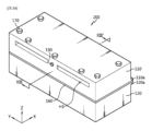
図13は、本発明の他の実施形態によるスロットダイコーターを示す斜視図であり、図14は、変形例の図である。図15と図16は、それぞれ図13と図14に示すスロットダイコーターの幅方向に垂直な断面図であって、図13と図14のXIII-XIII’矢視断面に相当する。図17は、図13に示すスロットダイコーターの変形例であって、他の方向からの斜視図であって、スロットダイコーターの前方を示している。図18は、図13に示すスロットダイコーターに含まれ得るシムの一例を示す斜視図である。図19は、図17の部分拡大図である。図20は、図17に示すスロットダイコーターの他の方向からの斜視図であって、スロットダイコーターの後方を示している。図21は、図20の変形例である。 Figure 13 is a perspective view showing a slot die coater according to another embodiment of the present invention, and Figure 14 is a view of a modified example. Figures 15 and 16 are cross-sectional views perpendicular to the width direction of the slot die coater shown in Figures 13 and 14, respectively, and correspond to the cross-sections seen from the arrows XIII-XIII' in Figures 13 and 14. Figure 17 is a perspective view from another direction of a modified example of the slot die coater shown in Figure 13, showing the front of the slot die coater. Figure 18 is a perspective view showing an example of a shim that can be included in the slot die coater shown in Figure 13. Figure 19 is a partially enlarged view of Figure 17. Figure 20 is a perspective view from another direction of the slot die coater shown in Figure 17, showing the rear of the slot die coater. Figure 21 is a modified example of Figure 20.
以上の図面を参照して本発明の他の実施形態によるスロットダイコーターについて説明する。 With reference to the above drawings, we will now explain a slot die coater according to another embodiment of the present invention.
前述したスロットダイコーター100と比較して、本発明の他の実施形態によるスロットダイコーター200は、上板110に存在していたテーパーブロック180の固定及び押圧のためのボルト溝H2がなく、その位置に幅方向に長孔H3を加工する。
Compared to the
長孔H3は、押圧ボルト190が差し込み可能なように上板110の背面に幅方向に長尺状に形成されている。
The long hole H3 is formed in a long shape in the width direction on the back surface of the
押圧ボルト190は、上板110の背面から上板110を貫通してテーパーブロック180に締結される。すなわち、押圧ボルト190は、上板110の背面の部分から挿し込まれてテーパーブロック180にまで入り込む。このために、テーパーブロック180内に押圧ボルト190が締結可能なねじ線を加工する。先の実施形態との相違点は、押圧ボルト190が上板110の背面においてテーパーブロック180に締結されるということである。押圧ボルト190の操作は、上板110の背面において行われる。コーティング液の吐き出しが行われる前方部ではなく、後方部において押圧ボルト190の操作が行われるので、作業、メンテナンスなどの管理をより一層行い易い。
The
長孔H3が幅方向に長尺状に形成されていて、形成すべきパターンの数に対応するように押圧ボルト190を追加することができ、上板110の前面に形成されている溝H1にテーパーブロック180をそれに対応する数で追加することができる。すなわち、パターンごとに別途に構成可能である。
The long hole H3 is formed long in the width direction, so that the
特に、図13と図15を参照すると、長孔H3は、押圧ボルト190の直径と略同一のサイズに形成されている。押圧ボルト190は、無地となっており、端部にねじ線が形成されている。長孔H3の断面の形状と押圧ボルト190の形状は、図示の形状に何ら限定されるものではなく、格別制限なしに変形可能である。長孔H3は、上板110の背面に幅方向に長尺状に形成されている。長孔H3の任意の位置に押圧ボルト190を位置させ易い仕組みである。
In particular, referring to Figures 13 and 15, the long hole H3 is formed to be approximately the same size as the diameter of the
変形例である図14と図16を参照すると、長孔H3は、押圧ボルト190の直径よりも大きなサイズに形成されている。押圧ボルト190がこのような長孔H3内において空回りしないように、長孔H3の前面の中間、上板110の背面が掛け金具の役割を果たすように閉塞されている。長孔H3が先の実施形態よりは広く形成されていて、押圧ボルト190による締結応力が上板110にかからないような仕組みである。
Referring to the modified examples in Figures 14 and 16, the long hole H3 is formed to be larger than the diameter of the
一方、図17と図20及び図21においては、テーパーブロック180が2つである場合を詳しく例示している。この場合に使用可能なシム160は、図18に示されている。
On the other hand, Figures 17, 20, and 21 show a detailed example of a case where there are two taper blocks 180. The
図18を参照すると、シム160は、3つの開放部160aを含むようにベース部161に垂直に接続されて吐出口140側に延びる4つの延在部162を含み得る。テーパーブロック180は、4つの延在部162のうち、左右の両端(サイド)を除いた残りの2つの延在部162に対応するように配備される。
Referring to FIG. 18, the
このように、本発明の他の実施形態によれば、シム160の位置に合うようにテーパーブロック180の数を増やすことができ、位置を変更することができる。したがって、押圧ボルト190とテーパーブロック180が幅方向に沿って複数配備され得る。なお、シム160の形状が変更される場合、テーパーブロック180及び押圧ボルト190の位置を幅方向に所望の個所に変更することができる。
In this way, according to another embodiment of the present invention, the number of taper blocks 180 can be increased and their positions can be changed to match the positions of the
図19でのように、テーパーブロック180と押圧ボルト190は、スロットギャップGには影響を及ぼさないので、スロットギャップGは、設定したシム160の厚さHに対応するように保たれることが可能になる。すなわち、本発明において、スロットギャップGのサイズはシム160の厚さHに調整し、テーパーブロック180及び押圧ボルト190は、スロットギャップGに影響を及ぼすことなく、シム160を押し付けて上板110と下板120との広がりを防ぐ。
As shown in FIG. 19, the
テーパーブロック180は、幅方向に複数配備され得る。テーパーブロック180が複数であり、相互間の間隔が一定になるように調整する場合、より一層一様に力を伝達可能であり、安定した釣り合い状態をなして、上板110と下板120の歪みを防ぐことができる。
The taper blocks 180 may be arranged in multiple width directions. When multiple taper blocks 180 are used and the spacing between them is adjusted to be uniform, force can be transmitted more uniformly, creating a stable balanced state and preventing distortion of the
テーパーブロック180と押圧ボルト190を介して、ダイリップ110a、120aの部分が広がることがない。そのため、シム160における活物質スラリーを塞いで吐き出しができないようにすべき部分にまで活物質スラリーが入り込むことがなくなる。
The die
一方、先の実施形態において、スロットダイコーター100、200は、コーティング液である活物質スラリーを重力の反対の方向に吐き出す垂直ダイタイプである場合を例にとって説明したが、吐出口140の方向を略水平に配設して水平ダイタイプに構成する場合であっても本発明が適用可能である(略:±5°)。なお、スロットダイコーター100、200は、上板110と下板120との間に単層のスロット130を有する場合について説明したが、上板、中板及び下板を含んでスロットを2層に形成したデュアルスロットダイコーターによっても本発明が実現可能である。
Meanwhile, in the previous embodiment, the
以上、本発明を限定された実施形態と図面によって説明したが、本発明はこれらに限定されるものではなく、本発明が属する技術分野において通常の知識を有する者によって本発明の技術思想と特許請求の範囲の均等範囲内で様々な修正及び変形が可能であることは言うまでもない。 The present invention has been described above using limited embodiments and drawings, but the present invention is not limited to these, and it goes without saying that various modifications and variations are possible within the scope of the technical concept of the present invention and the scope of the claims by a person with ordinary knowledge in the technical field to which the present invention pertains.
100、200 スロットダイコーター
110 上板
110a、120a ダイリップ
120 下板
120b ランド
130 スロット
140 吐出口
150 マニホールド
160 シム
170 固定ボルト
180 テーパーブロック
190 押圧ボルト
REFERENCE SIGNS
Claims (18)
前記下板と前記上板との間に介在して前記吐出口と連通するスロットを形成するシムと、
を含み、
前記上板は、前記スロットの上側に前記シムと平行に前記上板の内部に湾入している溝を備え、
前記溝に差し込まれて前記シムを押し付けるテーパーブロック及び押圧ボルトをさらに含み、
前記溝の内側に向かって進むにつれて前記溝の高さが次第に低くなり、それに前記テーパーブロックの傾斜が合わせられている、スロットダイコーター。 an upper plate and a lower plate which are combined with each other to form a discharge port;
a shim interposed between the lower plate and the upper plate to form a slot communicating with the outlet;
Including,
the upper plate has a groove on an upper side of the slot, the groove extending inwardly of the upper plate and parallel to the shim;
The shim is further provided with a taper block and a pressing bolt that are inserted into the groove and press the shim.
A slot die coater , wherein the height of the groove gradually decreases as it progresses toward the inside of the groove, and the inclination of the tapered block is adjusted to the height of the groove .
前記下板と前記上板との間に介在して前記吐出口と連通するスロットを形成するシムと、
を含み、
前記上板は、前記スロットの上側に前記シムと平行に前記上板の内部に湾入している溝を備え、
前記溝に差し込まれて前記シムを押し付けるテーパーブロック及び押圧ボルトをさらに含み、
前記テーパーブロックは、前記押圧ボルトに締結されて前記吐出口の吐出方向と平行な方向において前後に動き、前記溝と前記テーパーブロックとの高さ差による力を生じさせて前記シムを押し付ける、スロットダイコーター。 an upper plate and a lower plate which are combined with each other to form a discharge port;
a shim interposed between the lower plate and the upper plate to form a slot communicating with the outlet;
Including,
the upper plate has a groove on an upper side of the slot, the groove extending inwardly of the upper plate and parallel to the shim;
The shim is further provided with a taper block and a pressing bolt that are inserted into the groove and press the shim.
The taper block is fastened to the pressure bolt and moves back and forth in a direction parallel to the discharge direction of the discharge port, generating a force due to a height difference between the groove and the taper block to press the shim.
前記下板と前記上板との間に介在して前記吐出口と連通するスロットを形成するシムと、
を含み、
前記上板は、前記スロットの上側に前記シムと平行に前記上板の内部に湾入している溝を備え、
前記溝に差し込まれて前記シムを押し付けるテーパーブロック及び押圧ボルトをさらに含み、
前記押圧ボルトは、前記上板の背面から前記上板を貫通して前記テーパーブロックに締結される、スロットダイコーター。 an upper plate and a lower plate which are combined with each other to form a discharge port;
a shim interposed between the lower plate and the upper plate to form a slot communicating with the outlet;
Including,
the upper plate has a groove on an upper side of the slot, the groove extending inwardly of the upper plate and parallel to the shim;
The shim is further provided with a taper block and a pressing bolt that are inserted into the groove and press the shim.
The pressing bolt penetrates the upper plate from a rear surface of the upper plate and is fastened to the taper block.
Applications Claiming Priority (5)
| Application Number | Priority Date | Filing Date | Title |
|---|---|---|---|
| KR20220094861 | 2022-07-29 | ||
| KR10-2022-0094861 | 2022-07-29 | ||
| KR10-2023-0062678 | 2023-05-15 | ||
| KR1020230062678A KR102912569B1 (en) | 2022-07-29 | 2023-05-15 | Slot die coater |
| PCT/KR2023/008781 WO2024025158A1 (en) | 2022-07-29 | 2023-06-23 | Slot die coater |
Publications (2)
| Publication Number | Publication Date |
|---|---|
| JP2024533682A JP2024533682A (en) | 2024-09-12 |
| JP7686881B2 true JP7686881B2 (en) | 2025-06-02 |
Family
ID=89706687
Family Applications (1)
| Application Number | Title | Priority Date | Filing Date |
|---|---|---|---|
| JP2024518490A Active JP7686881B2 (en) | 2022-07-29 | 2023-06-23 | Slot Die Coater |
Country Status (6)
| Country | Link |
|---|---|
| US (1) | US20240382997A1 (en) |
| EP (1) | EP4371672B1 (en) |
| JP (1) | JP7686881B2 (en) |
| ES (1) | ES3049410T3 (en) |
| HU (1) | HUE073450T2 (en) |
| WO (1) | WO2024025158A1 (en) |
Families Citing this family (3)
| Publication number | Priority date | Publication date | Assignee | Title |
|---|---|---|---|---|
| CN115551649A (en) * | 2020-09-28 | 2022-12-30 | 株式会社Lg新能源 | Double Slot Die Coater |
| KR20220094459A (en) * | 2020-12-29 | 2022-07-06 | 주식회사 엘지에너지솔루션 | Dual slot die coater |
| CN119281600A (en) * | 2024-12-13 | 2025-01-10 | 台州市黄岩晶威模具有限公司 | A coating die head |
Citations (3)
| Publication number | Priority date | Publication date | Assignee | Title |
|---|---|---|---|---|
| JP2008029918A (en) | 2006-07-26 | 2008-02-14 | Asahi Brain:Kk | Coating nozzle and coating device |
| CN101122747B (en) | 2006-08-09 | 2010-08-11 | 显示器生产服务株式会社 | Slot coating device |
| JP2013066853A (en) | 2011-09-22 | 2013-04-18 | Nec Corp | Coating die head |
Family Cites Families (12)
| Publication number | Priority date | Publication date | Assignee | Title |
|---|---|---|---|---|
| US6813820B2 (en) * | 2001-12-19 | 2004-11-09 | 3M Innovative Properties Company | Method of improving coating uniformity |
| JP4500669B2 (en) * | 2004-12-27 | 2010-07-14 | 東洋刃物株式会社 | Application head |
| KR100969358B1 (en) * | 2008-06-30 | 2010-07-09 | 주식회사 디엠에스 | Slit nozzle |
| KR100987184B1 (en) * | 2008-08-22 | 2010-10-11 | 주식회사 디엠에스 | Slit nozzle |
| JP5315453B1 (en) * | 2012-03-07 | 2013-10-16 | 日東電工株式会社 | Shim member, die coater and coating film manufacturing method |
| CN118151488A (en) | 2016-12-02 | 2024-06-07 | 三菱化学株式会社 | Colored photosensitive resin composition, pigment dispersion, partition wall, organic electroluminescent element, image display device and lighting |
| KR102362174B1 (en) * | 2018-10-01 | 2022-02-10 | 주식회사 엘지에너지솔루션 | Slot die coater adjusting device for adjusting the distance between the upper discharge port and the lower discharge port of the slot die coater and Electrode active material coating system comprising the same |
| KR102646381B1 (en) * | 2020-09-25 | 2024-03-08 | 주식회사 엘지에너지솔루션 | Dual slot die coater |
| CN115551648A (en) * | 2020-09-28 | 2022-12-30 | 株式会社Lg新能源 | Multi-slot die coater |
| CN115551649A (en) * | 2020-09-28 | 2022-12-30 | 株式会社Lg新能源 | Double Slot Die Coater |
| WO2022097985A1 (en) * | 2020-11-05 | 2022-05-12 | 주식회사 엘지에너지솔루션 | Slot die coater |
| KR102481190B1 (en) | 2020-12-29 | 2022-12-26 | 에브리봇 주식회사 | A robot cleaner |
-
2023
- 2023-06-23 ES ES23846817T patent/ES3049410T3/en active Active
- 2023-06-23 EP EP23846817.7A patent/EP4371672B1/en active Active
- 2023-06-23 JP JP2024518490A patent/JP7686881B2/en active Active
- 2023-06-23 WO PCT/KR2023/008781 patent/WO2024025158A1/en not_active Ceased
- 2023-06-23 US US18/692,658 patent/US20240382997A1/en active Pending
- 2023-06-23 HU HUE23846817A patent/HUE073450T2/en unknown
Patent Citations (3)
| Publication number | Priority date | Publication date | Assignee | Title |
|---|---|---|---|---|
| JP2008029918A (en) | 2006-07-26 | 2008-02-14 | Asahi Brain:Kk | Coating nozzle and coating device |
| CN101122747B (en) | 2006-08-09 | 2010-08-11 | 显示器生产服务株式会社 | Slot coating device |
| JP2013066853A (en) | 2011-09-22 | 2013-04-18 | Nec Corp | Coating die head |
Also Published As
| Publication number | Publication date |
|---|---|
| EP4371672B1 (en) | 2025-09-17 |
| EP4371672A4 (en) | 2024-11-20 |
| US20240382997A1 (en) | 2024-11-21 |
| EP4371672A1 (en) | 2024-05-22 |
| ES3049410T3 (en) | 2025-12-16 |
| HUE073450T2 (en) | 2026-01-28 |
| WO2024025158A1 (en) | 2024-02-01 |
| JP2024533682A (en) | 2024-09-12 |
Similar Documents
| Publication | Publication Date | Title |
|---|---|---|
| JP7686881B2 (en) | Slot Die Coater | |
| KR102774809B1 (en) | Dual slot die coater and electrode active material slurry coating method using the same | |
| JP7566152B2 (en) | Dual Slot Die Coater | |
| KR102920444B1 (en) | Slot die coater | |
| KR20230078497A (en) | Offset adjustable shim and slot die coater including the same | |
| JP7554938B2 (en) | Slot Die Coater | |
| KR102651932B1 (en) | Dual slot die coater | |
| JP7578824B2 (en) | Slot Die Coater | |
| KR102764210B1 (en) | Slot die coater | |
| JP2025536052A (en) | Method and apparatus for manufacturing electrodes for secondary batteries | |
| KR102912569B1 (en) | Slot die coater | |
| KR20230078468A (en) | Slot die coater | |
| KR102909149B1 (en) | Slot die coater | |
| KR20240020410A (en) | Slot die coater | |
| KR20250012882A (en) | Slot die coater and manufacturing method for electrode plate of secondary battery using the same | |
| KR102887256B1 (en) | Shim plate and slot die coater comprising the same | |
| CN117881487A (en) | Slot Die Coater | |
| EP4487965A1 (en) | Shim plate and slot die coater comprising same | |
| KR20230078471A (en) | Asymmetric shim plate and slot die coater comprising the same | |
| EP4732962A1 (en) | Slot die coater | |
| KR20240093322A (en) | Slot die coater and manufacturing method for electrode plate of secondary battery using the same | |
| KR20250109565A (en) | Slot die coater | |
| KR20240016867A (en) | Slot die coater | |
| CN118973719A (en) | Gasket and slot die coater including the same |
Legal Events
| Date | Code | Title | Description |
|---|---|---|---|
| A621 | Written request for application examination |
Free format text: JAPANESE INTERMEDIATE CODE: A621 Effective date: 20240322 |
|
| A131 | Notification of reasons for refusal |
Free format text: JAPANESE INTERMEDIATE CODE: A131 Effective date: 20241125 |
|
| A521 | Request for written amendment filed |
Free format text: JAPANESE INTERMEDIATE CODE: A523 Effective date: 20250225 |
|
| TRDD | Decision of grant or rejection written | ||
| A01 | Written decision to grant a patent or to grant a registration (utility model) |
Free format text: JAPANESE INTERMEDIATE CODE: A01 Effective date: 20250422 |
|
| A61 | First payment of annual fees (during grant procedure) |
Free format text: JAPANESE INTERMEDIATE CODE: A61 Effective date: 20250521 |
|
| R150 | Certificate of patent or registration of utility model |
Ref document number: 7686881 Country of ref document: JP Free format text: JAPANESE INTERMEDIATE CODE: R150 |