JP7686880B2 - Method for determining at least one elevation variable of an object target using an automotive radar system - Patents.com - Google Patents
Method for determining at least one elevation variable of an object target using an automotive radar system - Patents.com Download PDFInfo
- Publication number
- JP7686880B2 JP7686880B2 JP2024516965A JP2024516965A JP7686880B2 JP 7686880 B2 JP7686880 B2 JP 7686880B2 JP 2024516965 A JP2024516965 A JP 2024516965A JP 2024516965 A JP2024516965 A JP 2024516965A JP 7686880 B2 JP7686880 B2 JP 7686880B2
- Authority
- JP
- Japan
- Prior art keywords
- variable
- radar system
- object target
- directional
- relative
- Prior art date
- Legal status (The legal status is an assumption and is not a legal conclusion. Google has not performed a legal analysis and makes no representation as to the accuracy of the status listed.)
- Active
Links
Images


Classifications
-
- G—PHYSICS
- G01—MEASURING; TESTING
- G01S—RADIO DIRECTION-FINDING; RADIO NAVIGATION; DETERMINING DISTANCE OR VELOCITY BY USE OF RADIO WAVES; LOCATING OR PRESENCE-DETECTING BY USE OF THE REFLECTION OR RERADIATION OF RADIO WAVES; ANALOGOUS ARRANGEMENTS USING OTHER WAVES
- G01S13/00—Systems using the reflection or reradiation of radio waves, e.g. radar systems; Analogous systems using reflection or reradiation of waves whose nature or wavelength is irrelevant or unspecified
- G01S13/88—Radar or analogous systems specially adapted for specific applications
- G01S13/93—Radar or analogous systems specially adapted for specific applications for anti-collision purposes
- G01S13/931—Radar or analogous systems specially adapted for specific applications for anti-collision purposes of land vehicles
-
- G—PHYSICS
- G01—MEASURING; TESTING
- G01S—RADIO DIRECTION-FINDING; RADIO NAVIGATION; DETERMINING DISTANCE OR VELOCITY BY USE OF RADIO WAVES; LOCATING OR PRESENCE-DETECTING BY USE OF THE REFLECTION OR RERADIATION OF RADIO WAVES; ANALOGOUS ARRANGEMENTS USING OTHER WAVES
- G01S13/00—Systems using the reflection or reradiation of radio waves, e.g. radar systems; Analogous systems using reflection or reradiation of waves whose nature or wavelength is irrelevant or unspecified
- G01S13/003—Bistatic radar systems; Multistatic radar systems
-
- G—PHYSICS
- G01—MEASURING; TESTING
- G01S—RADIO DIRECTION-FINDING; RADIO NAVIGATION; DETERMINING DISTANCE OR VELOCITY BY USE OF RADIO WAVES; LOCATING OR PRESENCE-DETECTING BY USE OF THE REFLECTION OR RERADIATION OF RADIO WAVES; ANALOGOUS ARRANGEMENTS USING OTHER WAVES
- G01S13/00—Systems using the reflection or reradiation of radio waves, e.g. radar systems; Analogous systems using reflection or reradiation of waves whose nature or wavelength is irrelevant or unspecified
- G01S13/02—Systems using reflection of radio waves, e.g. primary radar systems; Analogous systems
- G01S13/06—Systems determining position data of a target
- G01S13/42—Simultaneous measurement of distance and other co-ordinates
- G01S13/44—Monopulse radar, i.e. simultaneous lobing
- G01S13/4454—Monopulse radar, i.e. simultaneous lobing phase comparisons monopulse, i.e. comparing the echo signals received by an interferometric antenna arrangement
-
- G—PHYSICS
- G01—MEASURING; TESTING
- G01S—RADIO DIRECTION-FINDING; RADIO NAVIGATION; DETERMINING DISTANCE OR VELOCITY BY USE OF RADIO WAVES; LOCATING OR PRESENCE-DETECTING BY USE OF THE REFLECTION OR RERADIATION OF RADIO WAVES; ANALOGOUS ARRANGEMENTS USING OTHER WAVES
- G01S13/00—Systems using the reflection or reradiation of radio waves, e.g. radar systems; Analogous systems using reflection or reradiation of waves whose nature or wavelength is irrelevant or unspecified
- G01S13/02—Systems using reflection of radio waves, e.g. primary radar systems; Analogous systems
- G01S13/06—Systems determining position data of a target
- G01S13/46—Indirect determination of position data
-
- G—PHYSICS
- G01—MEASURING; TESTING
- G01S—RADIO DIRECTION-FINDING; RADIO NAVIGATION; DETERMINING DISTANCE OR VELOCITY BY USE OF RADIO WAVES; LOCATING OR PRESENCE-DETECTING BY USE OF THE REFLECTION OR RERADIATION OF RADIO WAVES; ANALOGOUS ARRANGEMENTS USING OTHER WAVES
- G01S13/00—Systems using the reflection or reradiation of radio waves, e.g. radar systems; Analogous systems using reflection or reradiation of waves whose nature or wavelength is irrelevant or unspecified
- G01S13/02—Systems using reflection of radio waves, e.g. primary radar systems; Analogous systems
- G01S13/50—Systems of measurement based on relative movement of target
- G01S13/58—Velocity or trajectory determination systems; Sense-of-movement determination systems
- G01S13/589—Velocity or trajectory determination systems; Sense-of-movement determination systems measuring the velocity vector
-
- G—PHYSICS
- G01—MEASURING; TESTING
- G01S—RADIO DIRECTION-FINDING; RADIO NAVIGATION; DETERMINING DISTANCE OR VELOCITY BY USE OF RADIO WAVES; LOCATING OR PRESENCE-DETECTING BY USE OF THE REFLECTION OR RERADIATION OF RADIO WAVES; ANALOGOUS ARRANGEMENTS USING OTHER WAVES
- G01S7/00—Details of systems according to groups G01S13/00, G01S15/00, G01S17/00
- G01S7/02—Details of systems according to groups G01S13/00, G01S15/00, G01S17/00 of systems according to group G01S13/00
- G01S7/41—Details of systems according to groups G01S13/00, G01S15/00, G01S17/00 of systems according to group G01S13/00 using analysis of echo signal for target characterisation; Target signature; Target cross-section
-
- B—PERFORMING OPERATIONS; TRANSPORTING
- B60—VEHICLES IN GENERAL
- B60W—CONJOINT CONTROL OF VEHICLE SUB-UNITS OF DIFFERENT TYPE OR DIFFERENT FUNCTION; CONTROL SYSTEMS SPECIALLY ADAPTED FOR HYBRID VEHICLES; ROAD VEHICLE DRIVE CONTROL SYSTEMS FOR PURPOSES NOT RELATED TO THE CONTROL OF A PARTICULAR SUB-UNIT
- B60W2420/00—Indexing codes relating to the type of sensors based on the principle of their operation
- B60W2420/40—Photo, light or radio wave sensitive means, e.g. infrared sensors
- B60W2420/408—Radar; Laser, e.g. lidar
-
- G—PHYSICS
- G01—MEASURING; TESTING
- G01S—RADIO DIRECTION-FINDING; RADIO NAVIGATION; DETERMINING DISTANCE OR VELOCITY BY USE OF RADIO WAVES; LOCATING OR PRESENCE-DETECTING BY USE OF THE REFLECTION OR RERADIATION OF RADIO WAVES; ANALOGOUS ARRANGEMENTS USING OTHER WAVES
- G01S13/00—Systems using the reflection or reradiation of radio waves, e.g. radar systems; Analogous systems using reflection or reradiation of waves whose nature or wavelength is irrelevant or unspecified
- G01S13/02—Systems using reflection of radio waves, e.g. primary radar systems; Analogous systems
- G01S2013/0236—Special technical features
- G01S2013/0245—Radar with phased array antenna
- G01S2013/0263—Passive array antenna
-
- G—PHYSICS
- G01—MEASURING; TESTING
- G01S—RADIO DIRECTION-FINDING; RADIO NAVIGATION; DETERMINING DISTANCE OR VELOCITY BY USE OF RADIO WAVES; LOCATING OR PRESENCE-DETECTING BY USE OF THE REFLECTION OR RERADIATION OF RADIO WAVES; ANALOGOUS ARRANGEMENTS USING OTHER WAVES
- G01S13/00—Systems using the reflection or reradiation of radio waves, e.g. radar systems; Analogous systems using reflection or reradiation of waves whose nature or wavelength is irrelevant or unspecified
- G01S13/88—Radar or analogous systems specially adapted for specific applications
- G01S13/93—Radar or analogous systems specially adapted for specific applications for anti-collision purposes
- G01S13/931—Radar or analogous systems specially adapted for specific applications for anti-collision purposes of land vehicles
- G01S2013/932—Radar or analogous systems specially adapted for specific applications for anti-collision purposes of land vehicles using own vehicle data, e.g. ground speed, steering wheel direction
-
- G—PHYSICS
- G01—MEASURING; TESTING
- G01S—RADIO DIRECTION-FINDING; RADIO NAVIGATION; DETERMINING DISTANCE OR VELOCITY BY USE OF RADIO WAVES; LOCATING OR PRESENCE-DETECTING BY USE OF THE REFLECTION OR RERADIATION OF RADIO WAVES; ANALOGOUS ARRANGEMENTS USING OTHER WAVES
- G01S13/00—Systems using the reflection or reradiation of radio waves, e.g. radar systems; Analogous systems using reflection or reradiation of waves whose nature or wavelength is irrelevant or unspecified
- G01S13/88—Radar or analogous systems specially adapted for specific applications
- G01S13/93—Radar or analogous systems specially adapted for specific applications for anti-collision purposes
- G01S13/931—Radar or analogous systems specially adapted for specific applications for anti-collision purposes of land vehicles
- G01S2013/9327—Sensor installation details
- G01S2013/93271—Sensor installation details in the front of the vehicles
Landscapes
- Engineering & Computer Science (AREA)
- Radar, Positioning & Navigation (AREA)
- Remote Sensing (AREA)
- Physics & Mathematics (AREA)
- Computer Networks & Wireless Communication (AREA)
- General Physics & Mathematics (AREA)
- Electromagnetism (AREA)
- Radar Systems Or Details Thereof (AREA)
Description
本発明は、レーダシステム、特に車両のレーダシステムによって検出される物体の物体目標の少なくとも1つの仰角変数を、仰角基準面に対して決定するための方法に関し、
レーダシステムを使用して、レーダ信号を放射し、物体目標で反射されたレーダ信号からのエコー信号を受信し、
レーダシステムの移動速度を決定し、
レーダシステムに対する少なくとも1つの物体目標の半径方向速度は、受信されたエコー信号によってレーダシステムを使用して決定され、
レーダシステムに対して固定された第1の基準領域に対する物体目標の方向を特徴付ける第1の方向変数が、受信されたエコー信号によってレーダシステムを使用して決定され、
レーダシステムに対して固定された第2の基準領域に対する物体目標の方向を特徴付ける第2の方向変数が、第1の方向変数、半径方向速度、及び移動速度によって決定され、
物体目標の少なくとも1つの仰角変数は、方向変数のうちの少なくとも1つによって決定される。
The present invention relates to a method for determining at least one elevation variable of an object target detected by a radar system, in particular a vehicle radar system, relative to an elevation reference plane,
Using a radar system to emit a radar signal and receive an echo signal from the radar signal reflected by an object target;
Determining the speed of movement of the radar system;
a radial velocity of at least one object target relative to the radar system is determined using the radar system from the received echo signals;
a first directional variable characterizing a direction of the object target relative to a first reference region fixed relative to the radar system is determined using the radar system from the received echo signals;
a second directional variable characterizing a direction of the object target relative to a second reference region fixed relative to the radar system is determined by the first directional variable, the radial velocity, and the moving velocity;
At least one elevation variable of the object target is determined by at least one of the orientation variables.
さらに、本発明は、特に車両のレーダシステムに関し、
レーダ信号を放射するための少なくとも1つのアンテナと、
物体目標で反射されたレーダ信号のエコー信号を受信するための少なくとも1つのアンテナと、
仰角基準面に対して、レーダシステムを使用して検出された物体の物体目標から少なくとも1つの仰角変数を決定するための手段であって、
手段は、受信されたエコー信号によってレーダシステムに対する検出された物体目標の半径方向速度を決定するための手段と、
受信されたエコー信号によって、レーダシステムに対して固定された第1の基準領域に対する物体目標の方向を特徴付ける第1の方向変数を決定する手段と、
レーダシステムに対して固定された第2の基準領域に対する物体目標の方向を特徴付ける第2の方向変数を、レーダシステムの第1の方向変数、半径方向速度、及び移動速度によって決定する手段と、
方向変数のうちの少なくとも1つによって物体目標の少なくとも1つの仰角変数を決定する手段と、有する手段と、を備える。
Furthermore, the present invention relates to radar systems, especially for vehicles,
at least one antenna for emitting a radar signal;
at least one antenna for receiving an echo signal of the radar signal reflected by an object target;
means for determining at least one elevation variable from an object target detected using a radar system relative to an elevation reference plane, said means comprising:
The means includes means for determining the radial velocity of a detected object target relative to the radar system from the received echo signals;
means for determining, from the received echo signals, a first directional variable characterizing the orientation of the object target relative to a first reference region fixed relative to the radar system;
means for determining a second directional variable characterizing a direction of the object target relative to a second reference region fixed relative to the radar system according to the first directional variable, the radial velocity and the moving velocity of the radar system;
The system includes a means for determining at least one elevation variable of the object target according to at least one of the orientation variables.
さらに、本発明は、少なくとも1つのレーダシステムを有する車両に関し、
少なくとも1つのレーダシステムは、
レーダ信号を放射するための少なくとも1つのアンテナと、
物体目標で反射されたレーダ信号のエコー信号を受信するための少なくとも1つのアンテナと、
仰角基準面に対して、レーダシステムを使用して検出された物体の物体目標から少なくとも1つの仰角変数を決定するための手段であって、
手段は、受信されたエコー信号によってレーダシステムに対する検出された物体目標の半径方向速度を決定するための手段と、
受信されたエコー信号によって、レーダシステムに対して固定された第1の基準領域に対する物体目標の方向を特徴付ける第1の方向変数を決定する手段と、
レーダシステムに対して固定された第2の基準領域に対する物体目標の方向を特徴付ける第2の方向変数を、レーダシステムの第1の方向変数、半径方向速度、及び移動速度によって決定する手段と、
方向変数のうちの少なくとも1つによって物体目標の少なくとも1つの仰角変数を決定する手段と、有する手段と、を備える。
Furthermore, the present invention relates to a vehicle comprising at least one radar system,
At least one radar system
at least one antenna for emitting a radar signal;
at least one antenna for receiving an echo signal of the radar signal reflected by an object target;
means for determining at least one elevation variable from an object target detected using a radar system relative to an elevation reference plane, said means comprising:
The means includes means for determining the radial velocity of a detected object target relative to the radar system from the received echo signals;
means for determining, from the received echo signals, a first directional variable characterizing the orientation of the object target relative to a first reference region fixed relative to the radar system;
means for determining a second directional variable characterizing a direction of the object target relative to a second reference region fixed relative to the radar system according to the first directional variable, the radial velocity and the moving velocity of the radar system;
The system includes a means for determining at least one elevation variable of the object target according to at least one of the orientation variables.
車両環境内の物体のレーダベースの測定及び/又は分類のための方法は、独国特許出願公開第102018000517号明細書から知られており、車両環境は、車両に配置された少なくとも1つのレーダセンサによって検出され、ドップラ情報の項目は、レーダセンサによって放射されたレーダ信号と物体によって反射されたレーダ信号との間のドップラ周波数のシフトの評価に基づいて物体の高さの決定及び/又は分類時に生成される。車両の正確な移動情報の項目が利用可能であると仮定すると、仰角を正確に計算するために、物体の方位角に関する既に決定された情報が受信されたドップラ情報と共に利用されるという点で、物体の高さを決定することができる。物体の方位角は、レーダセンサの複数の水平アンテナでのデジタルビームフォーミングによって決定される。物体の仰角が一度計算されている場合、物体の高さは、式で規定されるように、物体の仰角及びレーダセンサから物体までの半径方向距離から決定することができる。
A method for radar-based measurement and/or classification of objects in a vehicle environment is known from
本発明は、仰角基準面に対する検出された物体目標の少なくとも1つの仰角変数の決定をより効率的に実装することができる、冒頭で述べた種類の方法、レーダシステム、及び車両を設計する目的に基づく。特に、少なくとも1つの仰角変数は、特により単純な及び/又は省スペースの手段を使用して、より正確に及び/又は容易に決定することができるべきである。 The invention is based on the object of designing a method, a radar system and a vehicle of the kind mentioned at the beginning, which allows a more efficient implementation of the determination of at least one elevation variable of a detected object target relative to an elevation reference plane. In particular, the at least one elevation variable should be more accurate and/or easier to determine, in particular using simpler and/or space-saving means.
本目的は、本方法のための本発明によれば、
レーダ信号は、レーダシステムの少なくとも1つのアンテナを使用して放射され、エコー信号は、レーダシステムの少なくとも2つのアンテナを使用して受信され、アンテナのそれぞれの位相中心は、仰角基準面に平行に延在する仮想アンテナ軸に沿って配置され、
第1の方向変数は、基準領域としてレーダシステムに対して固定された第1の基準軸に対して決定され、第2の方向変数は、基準領域としてレーダシステムに対して固定された第2の基準軸に対して決定される。
The object is according to the invention for the method
The radar signal is radiated using at least one antenna of the radar system and the echo signal is received using at least two antennas of the radar system, the phase centers of each of the antennas being disposed along a virtual antenna axis extending parallel to an elevation reference plane;
The first directional variable is determined relative to a first reference axis fixed relative to the radar system as a reference region, and the second directional variable is determined relative to a second reference axis fixed relative to the radar system as a reference region.
本発明によれば、アンテナ軸に沿って位相中心が配置されるアンテナを使用してレーダ信号を送受信する。アンテナ軸は、仰角基準面に平行に延在する。このようにして、レーダシステムのアンテナ配置は、簡単かつ省スペースで直線的に構築することができる。仰角基準面に平行なアンテナの配置は、方向変数の割り当てを単純化する。 According to the invention, radar signals are transmitted and received using an antenna whose phase center is located along the antenna axis. The antenna axis extends parallel to the elevation reference plane. In this way, the antenna arrangement of the radar system can be constructed in a simple, space-saving and linear manner. The arrangement of the antenna parallel to the elevation reference plane simplifies the assignment of directional variables.
本発明によれば、第1の方向変数及び第2の方向変数はそれぞれ、関連する基準軸に対して決定される。したがって、方向変数は、1次元線形アンテナ配置を使用して決定することができる。この目的のために、2次元の平面アンテナ配置は必要とされない。少なくとも1つの仰角変数を仰角基準面に対して直接決定できるようにするために、2次元平面アンテナ配置が必要とされる。本発明は、省スペースで簡単に設計された線形アンテナ配置を使用して、物体目標の仰角基準面に対して少なくとも1つの仰角変数を決定することを可能にする。 According to the invention, the first and second directional variables are each determined relative to an associated reference axis. The directional variables can therefore be determined using a one-dimensional linear antenna arrangement. For this purpose, a two-dimensional planar antenna arrangement is not required. A two-dimensional planar antenna arrangement is required in order to be able to determine at least one elevation variable directly relative to an elevation reference plane. The invention makes it possible to determine at least one elevation variable relative to an elevation reference plane of an object target using a space-saving and simply designed linear antenna arrangement.
仰角基準面は、レーダシステム、特に車両の法線方向に水平に延在する。方位角は、仰角基準面に平行に延在する平面内にあるか、又は仰角基準面であることが知られている。方位角が定義される方位角基準面は、仰角基準面に垂直である。 The elevation reference plane extends horizontally in a normal direction to the radar system, in particular to the vehicle. The azimuth angles lie in a plane that extends parallel to the elevation reference plane, or as it is known, the elevation reference plane. The azimuth reference plane, in which the azimuth angles are defined, is perpendicular to the elevation reference plane.
物体目標の半径方向速度は、物体目標とレーダシステムの基準点との間の仮想接続軸の方向における物体目標とレーダシステムとの間の相対速度である。レーダシステムの基準点は、有利には、少なくとも2つの基準軸の交点とすることができる。 The radial velocity of the object target is the relative velocity between the object target and the radar system in the direction of an imaginary connecting axis between the object target and a reference point of the radar system. The reference point of the radar system can advantageously be the intersection of at least two reference axes.
基準点、特に少なくとも2つの基準軸の交点、又は仰角基準面に垂直な方向への基準点の投影は、有利には、アンテナの位相中心間に、特にレーダシステムの仮想アンテナ軸上にあり得る。 The reference point, in particular the intersection of at least two reference axes or the projection of the reference point in a direction perpendicular to the elevation reference plane, may advantageously be between the phase centers of the antennas, in particular on a virtual antenna axis of the radar system.
基準点、特に少なくとも2つの基準軸の交点は、有利には、地面上の車両の車輪の接触領域によって画定される平面上に位置することができる。このようにして、方向変数のための基準軸を有する基準システムを、車両の車道に向けることができる。 The reference point, in particular the intersection of at least two reference axes, can advantageously be located on a plane defined by the contact area of the wheels of the vehicle on the ground. In this way, a reference system with a reference axis for the directional variables can be oriented on the roadway of the vehicle.
レーダシステムの移動速度は、レーダシステムが空間を移動する速度である。レーダシステムの移動速度は、有利には、車両の移動速度とすることができる。移動速度は、対地速度などと指定することができる。移動速度は、特に車両の速度測定システムを使用して有利に決定することができる。 The speed of movement of the radar system is the speed at which the radar system moves through space. The speed of movement of the radar system may advantageously be the speed of movement of the vehicle. The speed of movement may be specified as ground speed, etc. The speed of movement may advantageously be determined in particular using a speed measurement system of the vehicle.
本方法は、仰角基準面に対する物体目標の少なくとも1つの仰角変数を決定するために使用される。仰角変数は、有利には仰角高さであり得る。代替的又は追加的に、仰角変数は仰角であり得る。仰角高さは、物体目標と仰角基準面との間の距離である。仰角は、一方では物体目標とレーダシステムの基準点との間の仮想接続軸と、他方では仰角基準面との間の角度である。 The method is used to determine at least one elevation variable of the object target relative to an elevation reference plane. The elevation variable may advantageously be an elevation height. Alternatively or additionally, the elevation variable may be an elevation angle. The elevation height is the distance between the object target and the elevation reference plane. The elevation angle is the angle between an imaginary connection axis between the object target and a reference point of the radar system on the one hand and the elevation reference plane on the other hand.
さらに、本方法を使用して、物体目標の方位角を決定することができる。このようにして、本方法を使用して少なくとも1つの仰角変数と方位角の両方をより正確に決定することができる。 Furthermore, the method can be used to determine the azimuth angle of the object target. In this manner, the method can be used to more accurately determine both at least one elevation variable and the azimuth angle.
車両と組み合わせて使用すると、特に車両の進行方向前方に位置する物体目標の仰角高さを、本発明を使用して決定することができる。仰角高さが既知である場合、特に車両の運転者支援システムを使用して、物体目標が車両がその上を走行することができるほど十分に低く配置されているか、又は物体目標が車両が物体目標の下を通って走行することができるほど十分に高く配置されているかを判定することができる。 When used in conjunction with a vehicle, the present invention can be used to determine the elevation height of an object target, particularly one located ahead of the vehicle in the direction of travel. If the elevation height is known, the vehicle's driver assistance system can be used, among other things, to determine whether the object target is located low enough that the vehicle can drive over it, or whether the object target is located high enough that the vehicle can drive under it.
典型的には、検出された物体目標の方位角のみが、複数のアンテナ、特に放射アンテナ及び受信アンテナの線形配置のみを有するレーダシステムを使用して決定され得る。方位角は、ここではエコー信号の位相シフトに基づいて仮定することができる。エコー信号は、ここでは異なる受信アンテナを使用して検出される。物体目標がアンテナ、特に受信アンテナの位相中心と同じ仰角高さを有する場合にのみ、このようなレーダシステムを使用して方位角を正確に決定することができる。物体目標がアンテナとは異なる仰角高さに位置する場合、方位角は不正確に決定される。方位角及び仰角変数の両方を正確に決定できるようにするために、平面的に配置された放射アンテナ及び受信アンテナの構成が通常使用される。この場合、追加の放射チャネル及び受信チャネルが必要であり、それを使用して専ら仰角変数の決定が実行される。これは、使用されるレーダシステムの複雑さ及び費用支出を増加させる。これは、本発明では省略することができる。 Typically, only the azimuth angle of a detected object target can be determined using a radar system having only a linear arrangement of multiple antennas, in particular radiating and receiving antennas. The azimuth angle can be assumed here based on the phase shift of the echo signals, which are detected here using different receiving antennas. The azimuth angle can be accurately determined using such a radar system only if the object target has the same elevation height as the phase center of the antennas, in particular the receiving antennas. If the object target is located at a different elevation height than the antennas, the azimuth angle is determined inaccurately. In order to be able to accurately determine both the azimuth and elevation variables, a configuration of radiating and receiving antennas arranged in a plane is usually used. In this case, additional radiating and receiving channels are required, with which the determination of the elevation variable is carried out exclusively. This increases the complexity and cost expenditure of the radar system used, which can be omitted in the present invention.
本発明による方法及び本発明によるレーダシステムを使用して、レーダシステムに対する、特に車両に対する物体目標の距離及び方向を2次元平面内で決定することができる。物体目標は、少なくとも1つの仰角変数の正確な決定によって3次元空間において特徴付けることができる。全体として、本発明は、レーダシステム、特に車両の環境の完全な3次元マップを作成することを可能にする。本発明は、特に平面状に配置された追加のアンテナ、特に受信アンテナがこの目的のために必要とされることなく、1次元線形アンテナ配置を使用した方位角の決定及び少なくとも1つの仰角変数の決定の両方を改善することを可能にする。 Using the method according to the invention and the radar system according to the invention, the distance and direction of an object target relative to the radar system, in particular relative to a vehicle, can be determined in a two-dimensional plane. The object target can be characterized in three-dimensional space by accurate determination of at least one elevation angle variable. Overall, the invention makes it possible to create a complete three-dimensional map of the environment of the radar system, in particular of the vehicle. The invention makes it possible to improve both the determination of the azimuth angle and the determination of at least one elevation angle variable using a one-dimensional linear antenna arrangement, without additional antennas, in particular receiving antennas, arranged in a particular plane, being required for this purpose.
レーダシステムは、車両、特に自動車に有利に使用することができる。レーダシステムは、特に乗用車、トラック、バス、オートバイなど陸上車両、特にドローンなど航空機、及び/又は船舶に有利に使用することができる。レーダシステムはまた、自律的又は少なくとも半自律的に動作することができる車両に使用することができる。しかしながら、レーダシステムは車両に限定されない。それはまた、静止動作、ロボット工学、及び/又は機械、特にクレーン、掘削機などの建設又は輸送機械で使用することができる。 The radar system may be advantageously used in vehicles, in particular motor vehicles. The radar system may be advantageously used in land vehicles, in particular passenger cars, trucks, buses, motorcycles, aircraft, in particular drones, and/or marine vessels. The radar system may also be used in vehicles that can operate autonomously or at least semi-autonomously. However, the radar system is not limited to vehicles. It may also be used in stationary operations, robotics, and/or machines, in particular construction or transport machines, such as cranes, excavators, etc.
レーダシステムは、車両又は機械の少なくとも1つの電子制御装置、特に運転者支援システム及び/又はシャーシ制御システム及び/又は運転者情報装置及び/又は駐車支援システム及び/又はジェスチャ認識システムなどに有利に接続することができ、あるいはそのような装置又はシステムの一部とすることができる。このようにして、車両又は機械の機能の少なくともいくつかを、自律的又は半自律的に実施することができる。 The radar system can be advantageously connected to at least one electronic control device of the vehicle or machine, in particular a driver assistance system and/or a chassis control system and/or a driver information device and/or a parking assistance system and/or a gesture recognition system, etc., or can be part of such a device or system. In this way, at least some of the functions of the vehicle or machine can be performed autonomously or semi-autonomously.
本方法の有利な設計では、第1の方向変数は、様々なアンテナを使用して受信された同じレーダ信号のエコー信号間の位相シフトから決定することができる。このようにして、第1の方向変数をより正確に決定することができる。 In an advantageous design of the method, the first directional variable can be determined from the phase shift between echo signals of the same radar signal received using various antennas. In this way, the first directional variable can be determined more accurately.
本方法の1つの有利な実施形態では、第2の方向変数は、第1の方向変数、半径方向速度、及び移動速度、特に第2の方向角度の形態の第2の方向変数を、半径方向速度の商の逆正弦、並びに移動速度と第1の方向角度の形態の第1の方向変数の余弦との積として使用して、数学的、特に三角法の関係から計算することができる。このようにして、第2の方向変数は、既に決定された変数、特に第1の方向変数、半径方向速度、及び移動速度からより正確に計算することができる。したがって、第2の方向変数をより正確に個別に決定することができる。この目的のために、対応する変換テーブルは必要とされない。 In one advantageous embodiment of the method, the second direction variable can be calculated from mathematical, in particular trigonometric, relationships using the first direction variable, the radial speed and the movement speed, in particular the second direction variable in the form of a second direction angle, as the arcsine of the quotient of the radial speed and the product of the movement speed and the cosine of the first direction variable in the form of the first direction angle. In this way, the second direction variable can be calculated more accurately from the already determined variables, in particular the first direction variable, the radial speed and the movement speed. The second direction variable can therefore be determined more accurately and individually. For this purpose, a corresponding conversion table is not required.
第2の方向変数は、有利には、半径方向速度の商の逆正弦、並びに移動速度と第1の方向角度の形態の第1の方向変数の余弦との積として、第2の方向角度の形態で計算することができる。このようにして、方向変数は、方向角度の形態で直接計算することができる。 The second direction variable can advantageously be calculated in the form of a second direction angle as the arcsine of the quotient of the radial velocities and the product of the movement velocity and the cosine of the first direction variable in the form of the first direction angle. In this way, the direction variable can be calculated directly in the form of a direction angle.
第2の方向角度は、有利には、以下の式に従って計算することができる。
![]()
![]()
少なくとも1つの変換テーブルは、特にレーダシステムの較正の過程で、特にレーダシステム又は場合によっては車両の生産ラインの終わりに事前に決定することができ、レーダシステムの対応する記憶媒体、特に制御及び評価装置に格納することができる。 The at least one conversion table can be determined in advance, in particular in the course of calibration of the radar system, in particular at the end of a production line of the radar system or, as the case may be, of the vehicle, and can be stored in a corresponding storage medium of the radar system, in particular in the control and evaluation device.
有利には、それぞれの場合に異なる移動速度について変換テーブルを提供することができ、変換テーブルはそれぞれの走行速度について第1の方向変数、第2の方向変数、及び半径方向速度の間の関係を含む。このように、それぞれの移動速度に応じて適切な変換テーブルを用いることができる。 Advantageously, a conversion table can be provided for the different travel speeds in each case, the conversion table comprising for each travel speed the relationship between the first direction variable, the second direction variable and the radial speed. In this way, an appropriate conversion table can be used depending on the respective travel speed.
変換テーブルは、有利には、各々が第1の方向変数、半径方向速度、及び対応する第2の方向変数を有する複数のトリプルを有することができる。トリプルは、特にソフトウェアに容易に保存、特に格納することができる。 The conversion table may advantageously have a number of triples, each having a first direction variable, a radial velocity and a corresponding second direction variable. The triples may be easily stored, particularly in software.
本方法のさらに有利な実施形態では、第1の方向変数及び第2の方向変数は角度の形態で実装することができる。このようにして、検出された物体目標の少なくとも1つの仰角変数及び/又は方位角をより容易に決定することができる。 In a further advantageous embodiment of the method, the first direction variable and the second direction variable can be implemented in the form of angles. In this way, at least one elevation variable and/or azimuth angle of the detected object target can be more easily determined.
本方法のさらに有利な実施形態では、2つの基準軸は、仰角基準面に平行に又は仰角基準面内に延在する平面に及ぶように指定することができる。このようにして、方向変数の参照系と、少なくとも1つの仰角変数及び方位角の参照系とは、共通の向きを有することができる。したがって、少なくとも1つの仰角変数及び/又は方位角は、方向変数からより容易に決定することができる。 In a further advantageous embodiment of the method, the two reference axes can be specified to span a plane extending parallel to or within the elevation reference plane. In this way, the reference system for the direction variable and the reference system for the at least one elevation variable and the azimuth angle can have a common orientation. Thus, the at least one elevation variable and/or the azimuth angle can be more easily determined from the direction variable.
さらなる有利な実施形態では、第2の方向変数の決定の前に、検出された物体目標が静止しているかどうかをチェックすることができ、物体目標が静止していない場合、この物体目標の少なくとも1つの仰角変数を決定するための方法を終了することができ、そうでない場合、少なくとも1つの仰角変数を決定するための方法を継続することができる。このようにして、静止物体目標のみが、少なくとも1つの仰角変数を決定するために使用される。少なくとも1つの仰角変数は、静止物体目標を使用してより正確に決定することができる。 In a further advantageous embodiment, before the determination of the second direction variable, it can be checked whether the detected object target is stationary, and if the object target is not stationary, the method for determining at least one elevation variable of this object target can be terminated, otherwise the method for determining at least one elevation variable can be continued. In this way, only stationary object targets are used to determine the at least one elevation variable. The at least one elevation variable can be determined more accurately using the stationary object target.
終了後、物体目標の少なくとも1つの仰角変数を決定するための方法は、別の物体目標を使用して有利に再び開始することができる。 After completion, the method for determining at least one elevation variable of an object target can advantageously be started again using a different object target.
本方法のさらに有利な実施形態では、物体目標が静止しているかどうかをチェックするために、半径方向速度と、移動速度と第1の方向変数の余弦との積との間の差を計算することができ、
差を少なくとも1つの制限値と比較することができ、比較の結果に応じて、物体目標が静止しており、少なくとも1つの仰角変数を決定するための方法を継続することができると仮定することができ、そうでなければ、この物体目標について方法を終了することができ、
及び/又は
差を2つの指定された制限値と比較することができ、差が2つの制限値の間にある場合、物体目標は静止していると仮定することができ、少なくとも1つの仰角変数を決定するための方法を継続することができ、そうでなければ、この物体目標について方法を終了することができる。このようにして、空間内の物体目標の速度は、数学的に、特に三角法によって、移動速度、半径方向速度、及び第1の方向変数を考慮して決定することができる。
In a further advantageous embodiment of the method, in order to check whether the object target is stationary, it is possible to calculate the difference between the radial velocity and the product of the movement velocity and the cosine of the first directional variable,
The difference can be compared to at least one limit value, and depending on the result of the comparison, it can be assumed that the object target is stationary and the method for determining the at least one elevation angle variable can be continued, otherwise the method can be terminated for this object target;
and/or the difference can be compared to two specified limit values, and if the difference is between the two limit values, the object target can be assumed to be stationary and the method for determining at least one elevation angle variable can be continued, otherwise the method can be terminated for this object target. In this way, the velocity of the object target in space can be determined mathematically, in particular by trigonometry, taking into account the movement velocity, the radial velocity and the first directional variable.
半径方向速度と、移動速度と第1の方向変数の余弦との積との間の差は、少なくとも1つの制限値と有利に比較することができ、比較の結果に応じて、物体目標が静止していると仮定することができる。ここで、差が制限値未満又は制限値以下である場合、物体目標は静止していると仮定することができる。代替的又は追加的に、差が制限値超又は制限値以上である場合、物体目標は静止していると仮定することができる。 The difference between the radial velocity and the product of the movement velocity and the cosine of the first direction variable can be advantageously compared with at least one limit value, and depending on the result of the comparison, it can be assumed that the object target is stationary. Here, if the difference is less than or equal to the limit value, it can be assumed that the object target is stationary. Alternatively or additionally, if the difference is greater than or equal to the limit value, it can be assumed that the object target is stationary.
2つの制限値は、有利には異なる符号を有することができる。このようにして、レーダシステムに向かう方向への物体目標の動きは、レーダシステムから離れる物体目標の動きとは異なる符号を有する制限値を提供することができる。2つの制限値は、検出された物体目標の可能な動きを、許容誤差、特にレーダシステムの測定許容誤差及び/又は移動速度の許容誤差内で決定できるように指定することができる。 The two limit values can advantageously have different signs. In this way, a movement of an object target in a direction towards the radar system can be provided with a limit value having a different sign than a movement of an object target away from the radar system. The two limit values can be specified so that the possible movement of the detected object target can be determined within the tolerances, in particular the measurement tolerances and/or the movement speed tolerances of the radar system.
本方法のさらに有利な実施形態では、少なくとも1つの仰角変数及び/又は物体目標の方位角は、第1の方向変数及び第2の方向変数によって計算することができ、かつ/又は少なくとも1つの変換テーブルから取得することができる。このようにして、決定された方向変数は、より少ない労力で少なくとも1つの仰角変数及び/又は方位角に変換することができる。 In a further advantageous embodiment of the method, the at least one elevation variable and/or the azimuth angle of the object target can be calculated by the first direction variable and the second direction variable and/or can be obtained from at least one conversion table. In this way, the determined direction variable can be converted into the at least one elevation variable and/or the azimuth angle with less effort.
物体目標の少なくとも1つの仰角変数及び/又は方位角は、第1の方向変数及び第2の方向変数から有利に計算することができる。数学的、特に三角法の関係をこの目的のために使用することができる。 At least one elevation variable and/or azimuth angle of the object target can be advantageously calculated from the first direction variable and the second direction variable. Mathematical, in particular trigonometric, relationships can be used for this purpose.
仰角変数としての仰角高さの計算は、以下の式に従って実行することができる。
![]()
![]()
物体目標の距離は、レーダシステムを使用して有利に決定することができる。このようにして、物体目標に関連し、少なくとも1つの仰角変数を決定するために必要なすべての変数を、単一のレーダ測定を使用して決定することができる。 The range of the object target can be advantageously determined using a radar system. In this way, all variables related to the object target and necessary to determine at least one elevation variable can be determined using a single radar measurement.
代替的又は追加的に、少なくとも1つの仰角変数及び/又は方位角は、少なくとも1つの変換テーブルから取得することができる。このようにして、少なくとも1つの仰角変数及び/又は方位角は、追加の計算労力なしにより速く決定することができる。 Alternatively or additionally, the at least one elevation variable and/or the azimuth angle can be obtained from at least one conversion table. In this way, the at least one elevation variable and/or the azimuth angle can be determined faster without additional computational effort.
可能な仰角変数並びにそれぞれの第1の方向変数及び第2の方向変数を有するトリプルを、少なくとも1つの変換テーブルに有利に格納することができる。少なくとも1つの変換テーブルは、特にレーダシステムの較正の過程で、特にレーダシステムの生産ラインの終わりに事前に決定することができ、レーダシステムの対応する記憶媒体に格納することができる。 The triples with the possible elevation angle variables and the respective first and second direction variables can be advantageously stored in at least one conversion table. The at least one conversion table can be determined in advance, in particular in the course of calibration of the radar system, in particular at the end of the production line of the radar system, and can be stored in a corresponding storage medium of the radar system.
さらに、本発明によれば、レーダシステムにおいて、
レーダシステムは、使用してレーダ信号を放射することができる少なくとも1つのアンテナと、使用して物体目標で反射されたレーダ信号からエコー信号を受信することができる少なくとも2つのアンテナであって、アンテナのそれぞれの位相中心は、仰角基準面に平行に延在する仮想アンテナ軸に沿って配置される、アンテナと、
レーダシステムに対して第1の方向変数のための基準領域として固定された第1の基準軸と、第2の方向変数のための基準領域として固定された第2基準軸と、を有するということで目標が達成される。
Further, according to the present invention, in a radar system,
The radar system includes at least one antenna that can be used to radiate a radar signal and at least two antennas that can be used to receive echo signals from the radar signal reflected by an object target, the phase centers of each of the antennas being disposed along a virtual antenna axis that extends parallel to an elevation reference plane;
The objective is achieved by having a first reference axis fixed as a reference region for a first directional variable relative to the radar system and a second reference axis fixed as a reference region for a second directional variable.
本発明によれば、レーダシステムのアンテナは、仮想アンテナ軸に沿って直線的に配置される。このようにして、アンテナ配置を省スペースかつ簡単に設計することができる。さらに、アンテナ配置は、仰角基準面に対して規定された方法で配向することができる。したがって、少なくとも1つの仰角変数をより容易に決定することができる。レーダシステムは、固定された第1の基準軸及び固定された第2の基準軸を有し、これらは第1の方向変数及び第2の方向変数のための基準領域として使用される。 According to the invention, the antennas of the radar system are arranged linearly along a virtual antenna axis. In this way, the antenna arrangement can be designed in a space-saving and simple manner. Furthermore, the antenna arrangement can be oriented in a defined manner with respect to the elevation reference plane. Thus, at least one elevation variable can be more easily determined. The radar system has a fixed first reference axis and a fixed second reference axis, which are used as reference regions for the first and second directional variables.
さらに、本発明によれば、車両において、
少なくとも1つのレーダシステムは、使用してレーダ信号を放射することができる少なくとも1つのアンテナと、使用して物体目標で反射されたレーダ信号からエコー信号を受信することができる少なくとも2つのアンテナであって、アンテナのそれぞれの位相中心は、仰角基準面に平行に延在する仮想アンテナ軸に沿って配置される、アンテナと、
少なくとも1つのレーダシステムに対して第1の方向変数のための基準領域として固定された第1の基準軸と、第2の方向変数のための基準領域として固定された第2基準軸と、を有するということで目標が達成される。
Further, according to the present invention, in a vehicle,
At least one radar system includes at least one antenna that can be used to radiate radar signals and at least two antennas that can be used to receive echo signals from the radar signals reflected by object targets, the phase centers of each of the antennas being disposed along a virtual antenna axis that extends parallel to an elevation reference plane;
The objective is achieved by having at least one radar system have a first reference axis fixed as a reference region for a first directional variable and a second reference axis fixed as a reference region for a second directional variable.
有利には、基準軸の少なくとも1つは、車両の少なくとも1つの規定された仮想軸、特に車両長手方向軸、車両横断方向軸、及び/又は車両垂直方向軸、及び/又は車両の移動方向軸の方向に位置合わせすることができる。このように、少なくとも一つのレーダシステムを使用して得られた情報の項目を車両の環境情報の項目としてより容易に利用することができる。 Advantageously, at least one of the reference axes can be aligned in the direction of at least one defined virtual axis of the vehicle, in particular the longitudinal axis, the transverse axis and/or the vertical axis and/or the axis of the direction of movement of the vehicle. In this way, the items of information obtained using the at least one radar system can be more easily utilized as items of environmental information of the vehicle.
車両は、有利には、少なくとも1つの運転者支援システムを有することができる。車両は、運転者支援システムの助けを借りて自律的又は半自律的に動作することができる。 The vehicle may advantageously have at least one driver assistance system. The vehicle may operate autonomously or semi-autonomously with the aid of the driver assistance system.
少なくとも1つのレーダシステムは、有利には、少なくとも1つの運転者支援システムに機能的に接続することができる。このようにして、少なくとも1つのレーダシステムを使用して取得される車両の環境に関する情報の項目は、車両の自律的又は半自律的な動作のために少なくとも1つの運転者支援システムによって使用することができる。 The at least one radar system can advantageously be functionally connected to at least one driver assistance system. In this way, items of information about the environment of the vehicle acquired using the at least one radar system can be used by the at least one driver assistance system for autonomous or semi-autonomous operation of the vehicle.
少なくとも1つのレーダシステムは、有利には、特に、車両の運転者支援システム及び/又は自動運転システムの不可欠な構成要素とすることができる。レーダシステムは、検出された物体目標の半径方向速度をそれらを使用して直接決定することができるという利点を有する。 The at least one radar system can advantageously be an integral component, in particular, of a driver assistance system and/or an automated driving system of a vehicle. Radar systems have the advantage that the radial velocity of a detected object target can be determined directly using them.
さらに、本発明による方法、本発明によるレーダシステム、並びに本発明による車両及びそのそれぞれの有利な実施形態に関連して示された特徴及び利点は、ここでは相互に対応する方法で適用され、逆もまた同様である。個々の特徴及び利点は、当然、互いに組み合わせることができ、個々の効果の合計を超えるさらなる有利な効果が生じ得る。 Furthermore, the features and advantages indicated in relation to the method according to the invention, the radar system according to the invention, and the vehicle according to the invention and their respective advantageous embodiments apply here in a mutually corresponding manner and vice versa. The individual features and advantages can naturally be combined with one another, resulting in further advantageous effects that exceed the sum of the individual effects.
本発明のさらなる利点、特徴及び詳細は、本発明の例示的な実施形態が図面を参照してより詳細に説明される以下の説明から明らかになるであろう。当業者はまた、図面、明細書及び特許請求の範囲において組み合わせて開示されている特徴を個々に考慮することが好都合であり、それらを組み合わせて意味のあるさらなる組み合わせを形成する。概略図では、
図中、同一要素には同一符号を付している。 In the figure, the same elements are given the same symbols.
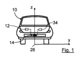
図1は、乗用車の形態の車両10の正面図を示す。車両10は、運転者支援システム12、速度測定システム34、及びレーダシステム14を備える。レーダシステム14は、運転者支援システム12に機能的に接続されており、車両10の進行方向前方の監視領域16を介してレーダシステム14を使用して得られる情報の項目を運転者支援システム12に送信することができる。車両10の機能、例えば運転機能は、運転者支援システム12を使用して自律的又は半自律的に実行することができる。
Figure 1 shows a front view of a
レーダシステム14は、一例として車両10のフロントフェンダに配置され、監視領域16内に向けられる。レーダシステム14はまた、車両10の異なる点に配置することができ、異なる向きにすることもできる。
The
監視領域16内の物体18は、レーダシステム14を使用して検出することができる。
物体18は、静止又は移動物体、例えば車両、人、動物、植物、障害物、道路の不規則性、例えば窪み又は石、道路境界、交通標識、空きスペース、例えば駐車スペース、降雨などであり得る。
The
レーダ信号20は、レーダシステム14を使用して監視領域16内に放射され、物体18を検出する。レーダシステム14の方向にある物体18の物体目標22で反射されたレーダ信号20は、レーダシステム14を使用してエコー信号24として受信される。物体情報、例えば距離R、半径方向速度VR、仰角Θ及び仰角高さhなどの仰角変数、並びにレーダシステム14の基準領域に対する、したがって車両10に対するそれぞれの物体目標22の方位角は、受信されたエコー信号24から決定することができる。
Radar signals 20 are emitted into the
物体目標22は、レーダ信号20を反射可能な物体18の領域である。物体18は、1つ又は複数のそのような物体目標22を有することができる。物体18が複数の物体目標22を有する場合、レーダ信号20はまた、その上で、例えば異なる方向に異なるように反射され得る。
An
図1~図4は、直交x-y-z座標系の対応する座標軸を示す。図2及び図4は、x-y-z座標系を3次元表現で示す。x-y-z座標系のx軸は、例えば、タイヤの接触面によって車両10の動作位置に広がる車両10の下方の平面に沿って車両10の車両長手方向軸に平行に延在する。y軸は、車両10の車両横断軸と平行に、進行方向左側に延在する。z軸は、車両10の車両垂直軸と平行に空間的に上方に延在する。x-y-z座標系の座標原点26のz軸方向の投影は、レーダシステム14の放射アンテナTxと受信アンテナRxとの間にある。座標原点26は、レーダシステム14の固定された基準点を形成する。
1 to 4 show the corresponding coordinate axes of an orthogonal x-y-z coordinate system. Figs. 2 and 4 show the x-y-z coordinate system in a three-dimensional representation. The x-axis of the x-y-z coordinate system extends parallel to the longitudinal axis of the
放射アンテナTx及び受信アンテナRxのそれぞれの位相中心28は、図3に示すように、仮想アンテナ軸30上に配置される。アンテナ軸30は、y軸に平行であり、x-y-z座標系のx-y平面に平行である。
The
x-y-z座標系のx-y平面は、レーダシステム14の仰角基準面31である。x-y-z座標系のx-z平面は、レーダシステム14の方位角基準面33である。方位角基準面33は、仰角基準面31に垂直である。
The x-y plane of the x-y-z coordinate system is the
レーダシステム14は、図3に示すように、3つの受信アンテナRxと1つの放射アンテナTxとを有する。図3は、監視領域16からx軸方向に観察した正面視における放射アンテナTx及び受信アンテナRxを示す。受信アンテナRx及び放射アンテナTxは、レーダシステム14の制御及び評価装置32に機能的に接続されている。制御及び評価装置32は、より明確にするために、放射アンテナTx及び受信アンテナRxの上方に例として示されている。別の点に配置することもできる。さらに、運転者支援システム12及び速度測定システム34が図3に示されている。
The
放射アンテナTxは、制御及び評価装置32を使用してレーダ信号20を放射するように作動され得る。エコー信号24は、受信アンテナRxを使用して受信され、電気信号に変換され得る。電気信号は、制御及び評価装置32に送信され、処理され得る。例えば、検出された物体18に関する物体情報の項目は、電気信号から決定することができる。
The radiating antenna Tx may be operated to radiate the
制御及び評価装置32は、運転者支援システム12に接続される。制御及び評価装置32を使用して決定された、例えば、検出された物体18に関する物体情報の項目などの情報の項目は、接続部を介して運転者支援システム12に送信することができる。送信された情報の項目は、車両10の自律的又は半自律的な動作のために運転者支援システム12によって使用することができる。
The control and
車両10の移動速度VHは、速度測定システム34を使用して決定することができる。速度測定システム34は、例えば、制御及び評価装置32に接続される。したがって、決定された移動速度VHをレーダシステム14に直接送信することができる。速度測定システム34は、例えば車両10の制御ユニットを介して、レーダシステム14及び/又は運転者支援システム12に間接的に接続することもできる。
The moving speed VH of the
レーダシステム14に対する検出された物体目標22の方向は、方位角Φ及び仰角Θの形態の仰角変数によって特徴付けられる。物体18の物体目標22の方位角Φ及び仰角Θを図4に示す。図4は、理解を容易にするために、座標系26を球面表現と併せて示している。
The orientation of a detected
方位角Φは、方位角基準面33と、物体目標22と仰角基準面31上の座標原点26との間の接続軸の正射影との間の角度である。仰角Θは、仰角基準面31と、座標原点26を有する物体目標22の接続軸との間の角度である。方位角Φ及び仰角Θは、それぞれの基準面、すなわち仰角基準面31及び方位角基準面33に対する物体目標22の方向を特徴付ける。
The azimuth angle Φ is the angle between the azimuth reference plane 33 and the orthogonal projection of the connection axis between the
検出された物体目標22の方向は、レーダシステム14を使用して、3つの受信アンテナRx間の受信されたエコー信号24の位相差の測定値から決定することができる。受信アンテナRxの線形配置により、位相差から第1の方向角度αの形態の第1の方向変数を決定することができる。
The direction of the detected
第1の方向角度αは、検出された物体目標22と座標原点26との間のx軸と接続軸との間の角度である。x軸は、第1の方向角度αに対するレーダシステム14の固定された第1の基準軸である。第1の方向角度αは、検出された物体目標22が仰角基準面31内にある場合、すなわちレーダシステム14と同じ仰角高さhにある場合にのみ方位角Φに対応する。
The first direction angle α is the angle between the x-axis and the connection axis between the detected
仰角高さhは、仰角基準面31の上方の高さであり、したがって仰角基準面31までの距離である。仰角高さh及び仰角Θは各々、物体目標22の位置も特徴付ける仰角変数である。
The elevation height h is the height above the
第2の方向角度βの形態の第2の方向変数は、第1の方向角度α、半径方向速度VR、及び検出された物体目標22の距離Rから決定することができる。
A second directional variable in the form of a second directional angle β can be determined from the first directional angle α, the radial velocity V R , and the range R of the detected
距離Rは、検出された物体目標22のレーダシステム14の基準点、すなわち座標原点26までの距離である。第2の方向角度βは、物体目標22と座標原点26との間のy軸と接続軸との間の角度である。y軸は、第2の方向角度βに対するレーダシステムの第2の固定された基準軸である。
The range R is the distance of the detected
方位角Φ、仰角Θ、及び仰角高さhは、物体目標22が第1の方向角度α及び第2の方向角度βから仰角基準面31の上方又は下方にある場合でも、物体目標に対して正確に決定することができる。
The azimuth angle Φ, elevation angle Θ, and elevation height h can be accurately determined for the
仰角変数、すなわち仰角Θ及び仰角高さh、並びに物体目標22の方位角を決定する方法を以下に説明する。
The method for determining the elevation variables, i.e., elevation angle Θ and elevation height h, and the azimuth angle of the
この目的のために、レーダシステム14の放射アンテナTxを使用してレーダ信号20が放射される。物体目標22で反射されるエコー信号24は、受信アンテナRxを使用して受信され、電気信号に変換され得る。
For this purpose, a
第1の方向角度αは、個々の受信アンテナRxを使用して受信されたエコー信号24間の位相差から決定される。さらに、エコー信号24から半径方向速度VR及び距離Rが決定される。さらに、車両10の移動速度VHが、速度測定システム34を使用して決定される。
The first direction angle α is determined from the phase difference between the echo signals 24 received using the individual receiving antennas Rx. Furthermore, the radial velocity V R and the range R are determined from the echo signals 24. Furthermore, the moving speed V H of the
次に、検出された物体目標22が静止しているか、又は動いているかどうかがチェックされる。この目的のために、半径方向速度VRと、移動速度VHと第1の方向角度αの余弦との積との間の差の形態のチェック項が、以下のように第1の制限値TH1及び第2の制限値TH2と比較される。
![]()
![]()
チェック項の値が2つの制限値TH1及びTH2の間にある場合、物体目標22は静止していると仮定される。静止物体目標22の場合、方位角Φ及び仰角Θの以下の決定は、移動物体目標22で可能であるよりも正確に実行することができる。したがって、より正確な結果を得るために、本方法は、静止しているときに物体目標22を使用してのみ継続される。チェック項を用いたチェックの結果、物体目標22が静止していなければ、別の物体目標22を使用して方位角Φ及び仰角変数、すなわち仰角Θ及び仰角高さhを決定する方法を再度実行する。
If the value of the check term lies between the two limit values TH1 and TH2, the
検出された物体目標22が静止しているとのチェックの結果が得られたと仮定して、第1の方向角度α、距離R、半径方向速度VR、及び、移動速度VHから、第2の方向角度βが決定される。これは、計算によって、又は変換テーブル36を使用して実行することができる。
Assuming that the check results show that the detected
計算は、例えば、以下の三角法の関係の助けを借りて実行される。
![]()
![]()
![]()
![]()
代替的又は追加的に、第2の方向角度βは、変換テーブル36によって決定することができる。この目的のために、例えば、変換テーブルの一群36が制御及び評価装置に格納される。これらの変換テーブル36のうちの1つの視覚化が、例として図5に示されている。変換テーブル36は、例えばレーダシステム14の較正の過程で、例えば生産ラインの終わりに事前に決定することができ、例えば制御及び評価装置32の対応する記憶媒体に格納することができる。
Alternatively or additionally, the second direction angle β can be determined by means of a conversion table 36. For this purpose, for example, a group of conversion tables 36 is stored in the control and evaluation device. A visualization of one of these conversion tables 36 is shown by way of example in FIG. 5. The conversion tables 36 can be determined in advance, for example in the course of calibration of the
一群の各変換テーブル36は、特定の移動速度VHに対応しており、この移動速度VHにおける第1の方向角度α、第2の方向角度β、及び半径方向速度VRの関係を含んでいる。変換テーブル36は、例えば、各々が第1の方向角度α、半径方向速度VR、及び対応する第2の方向角度βを有する複数のトリプルを各々有することができる。 Each of the group of conversion tables 36 corresponds to a particular moving speed VH and includes a relationship between a first direction angle α, a second direction angle β, and a radial speed V R at the moving speed VH . The conversion tables 36 may, for example, have a number of triples, each triple having a first direction angle α, a radial speed V R , and a corresponding second direction angle β.
図5に示す変換テーブル36では、第1の方向角度αが水平方向に示され、第2の方向角度βが垂直方向に示されている。異なる半径方向速度VRは、対応するフィールドに示される。 5, a first direction angle α is shown in the horizontal direction and a second direction angle β is shown in the vertical direction. The different radial velocities V R are shown in the corresponding fields.
より明確にするために、単に例として、第1の方向角度αについては10°から70°の値が10刻みに示され、第2の方向角度βについては10°から70°の値が10刻みに示されている。半径方向速度VRは、例として5m/s~20m/sの値で示されている。実際には、変換テーブル36は、第1の方向角度α及び第2の方向角度βについてかなりより多くの値を含むことができる。半径方向速度VRにも、相当により多くの異なる負及び正の値を含むことができる。 For clarity, and merely by way of example, values from 10° to 70° are shown for the first direction angle α in increments of 10, and values from 10° to 70° are shown for the second direction angle β in increments of 10. The radial velocity V R is shown with values from 5 m/s to 20 m/s by way of example. In practice, the conversion table 36 may include significantly more values for the first direction angle α and the second direction angle β. The radial velocity V R may also include significantly more different negative and positive values.
移動速度VHのマッチング変換テーブル36は、第2の方向角度βの決定に使用される。現在の移動速度VHについてマッチング変換テーブル36が存在しない場合には、現在の移動速度VHに最も近い移動速度についての変換テーブル36をここで使用することができる。対応する第2の方向角度βは、既に決定された第1の方向角度α及び既に決定された半径方向速度VRについて、対応する変換テーブル36から取得される。 The matching conversion table 36 of the moving speed VH is used to determine the second direction angle β. If there is no matching conversion table 36 for the current moving speed VH , the conversion table 36 for the moving speed closest to the current moving speed VH can be used here. The corresponding second direction angle β is obtained from the corresponding conversion table 36 for the already determined first direction angle α and the already determined radial speed VR .
例えば、半径方向速度VR=13m/sと組み合わせた第1の方向角度α=50°の場合のように、第1の方向角度α及び半径方向速度VRに対して複数の第2の方向角度βが利用可能である場合、例えば、(ここのさらなる関心ではない)妥当性チェックを実行して、2つの提供された第2の方向角度βのうちのどれが妥当であるかをチェックすることができる。 If multiple second direction angles β are available for a first direction angle α and a radial velocity V R , as for example for a first direction angle α=50° in combination with a radial velocity V R =13 m/s, then for example a validity check (not of further interest here) can be performed to check which of the two provided second direction angles β is valid.
方位角Φ及び仰角Θは、第1の方向角度α、第2の方向角度β、及び距離Rから三角法によって決定される。代替的に又は追加的に、方位角Φ及び仰角Θは、例えば、第1の方向角度α、第2の方向角度β、及び距離Rからの1つ又は複数の適切な変換テーブルの助けを借りて決定することができる。 The azimuth angle Φ and the elevation angle Θ are determined trigonometrically from the first direction angle α, the second direction angle β, and the distance R. Alternatively or additionally, the azimuth angle Φ and the elevation angle Θ can be determined, for example, with the aid of one or more suitable conversion tables from the first direction angle α, the second direction angle β, and the distance R.
物体目標22の仰角高さhは、以下の数学的関係から計算される。
![]()
![]()
代替的又は追加的に、仰角高さhは、第1の方向角度α、第2の方向角度β、及び距離Rから決定される代わりに、仰角Θ及び距離Rから決定することもできる。 Alternatively or additionally, the elevation height h can be determined from the elevation angle Θ and the distance R instead of being determined from the first directional angle α, the second directional angle β, and the distance R.
例えば、運転者支援システム12の手段を使用して実行することができる以下のチェックを使用して、物体目標22が、車両10がその上方又は下方を衝突することなく走行することができるほど十分に低く、又は十分に高く位置するかを、仰角高さhを用いて確立することができる。
For example, the following check, which can be performed using the means of the
Claims (11)
前記レーダシステム(14)を使用して、レーダ信号(20)が放射され、前記物体目標(22)で反射されたレーダ信号(20)のエコー信号(24)が受信され、
前記レーダシステム(14)の移動速度(VH)が決定され、
前記レーダシステム(14)に対する前記少なくとも1つの物体目標(22)の半径方向速度(VR)が、前記受信されたエコー信号(24)によって前記レーダシステム(14)を使用して決定され、
前記レーダシステム(14)に対して固定された第1の基準領域(y)に対する前記物体目標(22)の方向を特徴付ける第1の方向変数(α)が、前記受信されたエコー信号(24)によって前記レーダシステム(14)を使用して決定され、
前記レーダシステム(14)に対して固定された第2の基準領域(x)に対する前記物体目標(22)の方向を特徴付ける第2の方向変数(β)が、前記第1の方向変数(α)、前記半径方向速度(VR)、および前記移動速度(VH)によって決定され、
前記物体目標(22)の少なくとも1つの仰角変数(Θ、a)が、前記方向変数(α、β)の少なくとも1つによって決定され、
前記レーダシステム(14)の少なくとも1つのアンテナ(Tx)を使用してレーダ信号(20)が放射され、前記レーダシステム(14)の少なくとも2つのアンテナ(Rx)を使用してエコー信号(24)が受信され、前記アンテナ(Tx、Rx)のそれぞれの位相中心(28)が、前記仰角基準面(31)に平行に延在する仮想アンテナ軸(30)に沿って配置され、
前記第1の方向変数(α)が、前記基準領域として前記レーダシステム(14)に対して固定された第1の基準軸(y)に対して決定され、前記第2の方向変数(β)が、前記基準領域として前記レーダシステム(14)に対して固定された第2の基準軸(x)に対して決定されることを特徴とする、方法。 1. A method for determining at least one elevation angle variable (Θ, h) of an object target (22) of an object (18) detected by a radar system (14) relative to an elevation angle reference plane (31), comprising:
Using the radar system (14), a radar signal (20) is emitted and an echo signal (24) of the radar signal (20) reflected by the object target (22) is received;
A velocity ( VH ) of the radar system (14) is determined;
a radial velocity (V R ) of the at least one object target (22) relative to the radar system (14) is determined using the radar system (14) from the received echo signals (24);
a first directional variable (α) characterizing a direction of the object target (22) relative to a first reference region (y) fixed relative to the radar system (14) is determined using the radar system (14) from the received echo signals (24);
a second directional variable (β) characterizing the orientation of the object target (22) relative to a second reference region (x) fixed relative to the radar system (14) is determined by the first directional variable (α), the radial velocity (V R ) and the movement velocity (V H );
At least one elevation angle variable (Θ, a) of the object target (22) is determined by at least one of the directional variables (α, β);
A radar signal (20) is emitted using at least one antenna (Tx) of the radar system (14), and an echo signal (24) is received using at least two antennas (Rx) of the radar system (14), the phase centers (28) of each of the antennas (Tx, Rx) being arranged along a virtual antenna axis (30) extending parallel to the elevation reference plane (31);
The method according to claim 1, characterized in that the first directional variable (α) is determined relative to a first reference axis (y) fixed relative to the radar system (14) as the reference region, and the second directional variable (β) is determined relative to a second reference axis (x) fixed relative to the radar system (14) as the reference region.
β = arcsin(V R / (V H × cos α))
として計算されることを特徴とする、請求項1に記載の方法。 The second directional variable (β) is calculated from a mathematical relationship using the first directional variable (α), the radial velocity (V R ) and the displacement velocity (V H ), in particular the second directional variable (β) in the form of a second directional angle is calculated as:
β = arcsin(V R / (V H × cos α))
2. The method of claim 1, wherein the calculated value is:
前記差が少なくとも一つの制限値(TH1、TH2)と比較され、前記比較の結果に応じて、前記物体目標(22)が静止していると仮定され、前記少なくとも一つの仰角変数(Θ、h)を決定するための前記方法が継続され、そうでなければ、この物体目標(22)に対する前記方法が終了され、
および/または
前記差が2つの指定された制限値(TH1、TH2)と比較され、前記差が前記2つの制限値(TH1、TH2)の間にある場合、前記物体目標(22)が静止していると仮定され、前記少なくとも1つの仰角変数(Θ、h)を決定するための前記方法が継続され、そうでない場合、前記方法はこの物体目標(22)対して終了することを特徴とする、請求項7に記載の方法。 To check if the object target (22) is stationary, the difference between the radial velocity (V R ) and the product of the moving velocity (V H ) and the cosine of the first directional variable (α) is calculated;
said difference is compared with at least one limit value ( TH1 , TH2 ) and depending on the result of said comparison, said object target (22) is assumed to be stationary and said method for determining said at least one elevation angle variable (Θ, h) is continued, otherwise said method for this object target (22) is terminated;
and/or the method according to claim 7, characterized in that the difference is compared with two specified limit values ( TH1 , TH2 ) and, if the difference is between the two limit values ( TH1 , TH2 ), the object target (22) is assumed to be stationary and the method for determining the at least one elevation angle variable (Θ, h) is continued, and, if not, the method is terminated for this object target (22).
レーダ信号(20)を放射するための少なくとも一つのアンテナ(Tx)と、
物体目標(22)で反射されたレーダ信号(20)からのエコー信号(24)を受信するための少なくとも1つのアンテナ(Rx)と、
前記レーダシステム(14)を使用して検出された物体(18)の物体目標(22)の少なくとも一つの仰角変数(Θ、h)を、仰角基準面(31)に対して決定する手段であって、前記手段が、
受信されたエコー信号(24)によって前記レーダシステム(14)に対する検出された物体目標(22)の半径方向速度(VR)を決定する手段と、
受信されたエコー信号(24)によって、前記レーダシステム(14)に対して固定された第1の基準領域(y)に対する物体目標(22)の方向を特徴付ける第1の方向変数(α)を決定する手段と、
前記レーダシステム(14)に対して固定された第2の基準領域(x)に対する物体目標(22)の方向を特徴付ける第2の方向変数(β)を、前記レーダシステム(14)の第1の方向変数(α)、半径方向速度(VR)、および移動速度(VH)によって決定する手段と、
前記方向変数(α、β)のうちの少なくとも1つによって物体目標(22)の少なくとも1つの仰角変数(Θ、h)を決定する手段と、を有する、手段と、を備え、
前記レーダシステム(14)が、
使用してレーダ信号(20)を放射することができる少なくとも1つのアンテナ(Tx)と、使用して物体目標(22)で反射されたレーダ信号(20)からのエコー信号(24)を受信することができる少なくとも2つのアンテナ(Rx)であって、前記アンテナ(Tx、Rx)のそれぞれの位相中心(28)が、前記仰角基準面(31)に平行に延在する仮想アンテナ軸(30)に沿って配置される、アンテナ(Tx、Rx)と、
前記第1の方向変数(α)の前記基準領域として前記レーダシステム(14)に対して固定された第1の基準軸(y)と、前記第2の方向変数(β)の前記基準領域として固定された第2の基準軸(x)と、を有することを特徴とする、レーダシステム(14)。 A radar system (14), comprising:
at least one antenna (Tx) for radiating a radar signal (20);
at least one antenna (Rx) for receiving an echo signal (24) from a radar signal (20) reflected by an object target (22);
A means for determining at least one elevation angle variable (Θ, h) of an object target (22) of an object (18) detected using said radar system (14) relative to an elevation angle reference plane (31), said means comprising:
means for determining the radial velocity (V R ) of a detected object target (22) relative to said radar system (14) from received echo signals (24);
means for determining, from the received echo signals (24), a first directional variable (α) characterizing the direction of the object target (22) relative to a first reference region (y) fixed relative to said radar system (14);
means for determining a second directional variable (β) characterizing the direction of the object target (22) relative to a second reference region (x) fixed relative to the radar system (14) according to the first directional variable (α), the radial velocity (V R ) and the movement velocity (V H ) of the radar system (14);
and means for determining at least one elevation angle variable (Θ, h) of an object target (22) according to at least one of said directional variables (α, β),
The radar system (14),
at least one antenna (Tx) that can be used to radiate a radar signal (20) and at least two antennas (Rx) that can be used to receive an echo signal (24) from the radar signal (20) reflected by an object target (22), the phase centers (28) of each of the antennas (Tx, Rx) being disposed along a virtual antenna axis (30) that extends parallel to the elevation reference plane (31);
A radar system (14), characterized in that it has a first reference axis (y) fixed relative to the radar system (14) as the reference region of the first directional variable (α) and a second reference axis (x) fixed as the reference region of the second directional variable (β).
レーダ信号(20)を放射するための少なくとも一つのアンテナ(Tx)と、
物体目標(22)で反射されたレーダ信号(20)からのエコー信号(24)を受信するための少なくとも1つのアンテナ(Rx)と、
前記レーダシステム(14)を使用して検出された物体(18)の物体目標(22)の少なくとも一つの仰角変数(Θ、h)を、仰角基準面(31)に対して決定する手段であって、前記手段が、
受信されたエコー信号(24)によって前記レーダシステム(14)に対する検出された物体目標(22)の半径方向速度(VR)を決定する手段と、
受信されたエコー信号(24)によって、前記レーダシステム(14)に対して固定された第1の基準領域(y)に対する物体目標(22)の方向を特徴付ける第1の方向変数(α)を決定する手段と、
前記レーダシステム(14)に対して固定された第2の基準領域(x)に対する物体目標(22)の方向を特徴付ける第2の方向変数(β)を、前記レーダシステム(14)の第1の方向変数(α)、半径方向速度(VR)、および移動速度(VH)によって決定する手段と、
前記方向変数(α、β)のうちの少なくとも1つによって物体目標(22)の少なくとも1つの仰角変数(Θ、h)を決定する手段と、を有する、手段と、を備え、
前記少なくとも1つのレーダシステム(14)が、
使用してレーダ信号(20)を放射することができる少なくとも1つのアンテナ(Tx)と、使用して物体目標(22)で反射されたレーダ信号(20)からのエコー信号(24)を受信することができる少なくとも2つのアンテナ(Rx)であって、前記アンテナ(Tx、Rx)のそれぞれの位相中心(28)が、前記仰角基準面(31)に平行に延在する仮想アンテナ軸(30)に沿って配置される、アンテナ(Tx、Rx)と、
前記第1の方向変数(α)の前記基準領域として前記少なくとも1つのレーダシステム(14)に対して固定された第1の基準軸(y)と、前記第2の方向変数(β)の前記基準領域として固定された第2の基準軸(x)と、を有することを特徴とする、車両(10)。 A vehicle (10) having at least one radar system (14), the at least one radar system (14) comprising:
at least one antenna (Tx) for radiating a radar signal (20);
at least one antenna (Rx) for receiving an echo signal (24) from a radar signal (20) reflected by an object target (22);
A means for determining at least one elevation angle variable (Θ, h) of an object target (22) of an object (18) detected using said radar system (14) relative to an elevation angle reference plane (31), said means comprising:
means for determining the radial velocity (V R ) of a detected object target (22) relative to said radar system (14) from received echo signals (24);
means for determining, from the received echo signals (24), a first directional variable (α) characterizing the direction of the object target (22) relative to a first reference region (y) fixed relative to said radar system (14);
means for determining a second directional variable (β) characterizing the direction of the object target (22) relative to a second reference region (x) fixed relative to the radar system (14) according to the first directional variable (α), the radial velocity (V R ) and the movement velocity (V H ) of the radar system (14);
and means for determining at least one elevation angle variable (Θ, h) of an object target (22) according to at least one of said directional variables (α, β),
The at least one radar system (14)
at least one antenna (Tx) that can be used to radiate a radar signal (20) and at least two antennas (Rx) that can be used to receive an echo signal (24) from the radar signal (20) reflected by an object target (22), the phase centers (28) of each of the antennas (Tx, Rx) being disposed along a virtual antenna axis (30) that extends parallel to the elevation reference plane (31);
A vehicle (10), characterized in that it has a first reference axis (y) fixed relative to the at least one radar system (14) as the reference region of the first directional variable (α) and a second reference axis (x) fixed as the reference region of the second directional variable (β).
Applications Claiming Priority (3)
| Application Number | Priority Date | Filing Date | Title |
|---|---|---|---|
| DE102021123942.7A DE102021123942A1 (en) | 2021-09-16 | 2021-09-16 | Method for determining at least one elevation variable of an object target of an object, radar system and vehicle with at least one radar system |
| DE102021123942.7 | 2021-09-16 | ||
| PCT/EP2022/075341 WO2023041499A1 (en) | 2021-09-16 | 2022-09-13 | Method for determining at least one elevation variable of an object target using a motor vehicle radar system |
Publications (2)
| Publication Number | Publication Date |
|---|---|
| JP2024533580A JP2024533580A (en) | 2024-09-12 |
| JP7686880B2 true JP7686880B2 (en) | 2025-06-02 |
Family
ID=83558280
Family Applications (1)
| Application Number | Title | Priority Date | Filing Date |
|---|---|---|---|
| JP2024516965A Active JP7686880B2 (en) | 2021-09-16 | 2022-09-13 | Method for determining at least one elevation variable of an object target using an automotive radar system - Patents.com |
Country Status (7)
| Country | Link |
|---|---|
| US (1) | US20240377530A1 (en) |
| EP (1) | EP4402512A1 (en) |
| JP (1) | JP7686880B2 (en) |
| KR (1) | KR20240058175A (en) |
| CN (1) | CN117980777A (en) |
| DE (1) | DE102021123942A1 (en) |
| WO (1) | WO2023041499A1 (en) |
Citations (5)
| Publication number | Priority date | Publication date | Assignee | Title |
|---|---|---|---|---|
| WO2007111130A1 (en) | 2006-03-27 | 2007-10-04 | Murata Manufacturing Co., Ltd. | Radar apparatus and mobile unit |
| US20160103213A1 (en) | 2014-10-08 | 2016-04-14 | Texas Instruments Incorporated | Three Dimensional (3D) Tracking of Objects in a Radar System |
| DE102018000517A1 (en) | 2018-01-23 | 2018-08-23 | Daimler Ag | Method for radar-based measurement and / or classification of objects in a vehicle environment |
| JP2019518946A (en) | 2016-05-12 | 2019-07-04 | ヴァレオ・シャルター・ウント・ゼンゾーレン・ゲーエムベーハー | Radar sensor device for a motor vehicle, driver assistance system, motor vehicle and method for sensing an object |
| US20200191936A1 (en) | 2017-06-09 | 2020-06-18 | Veoneer Sweden Ab | Enhanced vertical object detection for a vehicle radar system |
Family Cites Families (9)
| Publication number | Priority date | Publication date | Assignee | Title |
|---|---|---|---|---|
| DE102008038365A1 (en) * | 2008-07-02 | 2010-01-07 | Adc Automotive Distance Control Systems Gmbh | Vehicle radar system and method for determining a position of at least one object relative to a vehicle |
| US8125373B2 (en) * | 2010-07-23 | 2012-02-28 | Toyota Motor Engineering & Manufacturing North America, Inc. | Microwave system utilizing elevational scanning by frequency hopping |
| DE102012220773A1 (en) * | 2012-11-14 | 2014-05-15 | Robert Bosch Gmbh | Device and method for elevation angle determination in a radar system |
| DE102015009382A1 (en) * | 2015-07-24 | 2016-01-21 | Daimler Ag | Method for radar-based determination of a height of an object |
| DE102015012246A1 (en) * | 2015-09-18 | 2016-03-03 | Daimler Ag | Method for determining a mounting orientation of a radar sensor |
| EP3293545A1 (en) * | 2016-09-09 | 2018-03-14 | Autoliv Development AB | Determining relative velocity in a vehicle radar system |
| DE102018218003A1 (en) * | 2018-10-22 | 2020-04-23 | Zf Friedrichshafen Ag | Process, computer program and measuring system for the evaluation of movement information |
| US11175382B2 (en) * | 2019-06-14 | 2021-11-16 | GM Global Technology Operations LLC | Elevation angle estimation in horizontal antenna array with doppler and velocity measurements |
| DE102020119934A1 (en) * | 2020-07-29 | 2022-02-03 | Valeo Schalter Und Sensoren Gmbh | Method for operating a radar system, radar system and vehicle with at least one radar system |
-
2021
- 2021-09-16 DE DE102021123942.7A patent/DE102021123942A1/en active Pending
-
2022
- 2022-09-13 KR KR1020247012529A patent/KR20240058175A/en active Pending
- 2022-09-13 JP JP2024516965A patent/JP7686880B2/en active Active
- 2022-09-13 US US18/691,403 patent/US20240377530A1/en active Pending
- 2022-09-13 EP EP22783479.3A patent/EP4402512A1/en active Pending
- 2022-09-13 WO PCT/EP2022/075341 patent/WO2023041499A1/en not_active Ceased
- 2022-09-13 CN CN202280062407.XA patent/CN117980777A/en active Pending
Patent Citations (5)
| Publication number | Priority date | Publication date | Assignee | Title |
|---|---|---|---|---|
| WO2007111130A1 (en) | 2006-03-27 | 2007-10-04 | Murata Manufacturing Co., Ltd. | Radar apparatus and mobile unit |
| US20160103213A1 (en) | 2014-10-08 | 2016-04-14 | Texas Instruments Incorporated | Three Dimensional (3D) Tracking of Objects in a Radar System |
| JP2019518946A (en) | 2016-05-12 | 2019-07-04 | ヴァレオ・シャルター・ウント・ゼンゾーレン・ゲーエムベーハー | Radar sensor device for a motor vehicle, driver assistance system, motor vehicle and method for sensing an object |
| US20200191936A1 (en) | 2017-06-09 | 2020-06-18 | Veoneer Sweden Ab | Enhanced vertical object detection for a vehicle radar system |
| DE102018000517A1 (en) | 2018-01-23 | 2018-08-23 | Daimler Ag | Method for radar-based measurement and / or classification of objects in a vehicle environment |
Also Published As
| Publication number | Publication date |
|---|---|
| EP4402512A1 (en) | 2024-07-24 |
| KR20240058175A (en) | 2024-05-03 |
| JP2024533580A (en) | 2024-09-12 |
| US20240377530A1 (en) | 2024-11-14 |
| CN117980777A (en) | 2024-05-03 |
| DE102021123942A1 (en) | 2023-03-16 |
| WO2023041499A1 (en) | 2023-03-23 |
Similar Documents
| Publication | Publication Date | Title |
|---|---|---|
| JP7008826B2 (en) | Automotive radar with antenna array with vertical offset for advanced phase angle measurements to enable 3D environment imaging of autonomous vehicles | |
| US20230204713A1 (en) | Radar System with Modified Orthogonal Linear Antenna Subarrays | |
| US12386064B2 (en) | Methods and systems for detecting and mitigating automotive radar interference | |
| KR20200040147A (en) | Apparatus and method for detecting mounting angle of radar | |
| JP2026507484A (en) | Method for operating a radar system that determines the location of a detected object using machine learning, radar system, driver assistance system, and vehicle | |
| CN105103004B (en) | Apparatus and method for determining elevation angle in a radar system | |
| US20250102658A1 (en) | Radar system for a vehicle, vehicle, and method for operating a radar system | |
| US20240319333A1 (en) | Method for assigning information channels of at least two sensors, each mounted in defined mounting positions relative to one another, to a detection device | |
| JP7686880B2 (en) | Method for determining at least one elevation variable of an object target using an automotive radar system - Patents.com | |
| CN116348787A (en) | Method of operating a radar system, radar system and vehicle comprising at least one radar system | |
| US20230341545A1 (en) | Near field radar beamforming | |
| US12172607B2 (en) | Atmospheric property estimation system and method in dynamic environments using LIDAR | |
| JP7767528B2 (en) | Radar system, antenna array for a radar system, vehicle equipped with at least one radar system, and method for operating at least one radar system | |
| US11719810B2 (en) | Automotive synthetic aperture radar with radon transform | |
| CN118393425A (en) | Radar system for jointly detecting arrival direction angle and departure direction angle in multipath scene | |
| KR20230043990A (en) | Radar systems, antenna arrays for radar systems, vehicles and how radar systems work | |
| KR20260003755A (en) | Method for processing sensor data, method for processing output data, and signal processing unit | |
| JP2022025661A (en) | Electronic apparatus, method for controlling electronic apparatus, and program |
Legal Events
| Date | Code | Title | Description |
|---|---|---|---|
| A521 | Request for written amendment filed |
Free format text: JAPANESE INTERMEDIATE CODE: A523 Effective date: 20240527 |
|
| A621 | Written request for application examination |
Free format text: JAPANESE INTERMEDIATE CODE: A621 Effective date: 20240508 |
|
| A131 | Notification of reasons for refusal |
Free format text: JAPANESE INTERMEDIATE CODE: A131 Effective date: 20250107 |
|
| A521 | Request for written amendment filed |
Free format text: JAPANESE INTERMEDIATE CODE: A523 Effective date: 20250407 |
|
| TRDD | Decision of grant or rejection written | ||
| A01 | Written decision to grant a patent or to grant a registration (utility model) |
Free format text: JAPANESE INTERMEDIATE CODE: A01 Effective date: 20250422 |
|
| A61 | First payment of annual fees (during grant procedure) |
Free format text: JAPANESE INTERMEDIATE CODE: A61 Effective date: 20250521 |
|
| R150 | Certificate of patent or registration of utility model |
Ref document number: 7686880 Country of ref document: JP Free format text: JAPANESE INTERMEDIATE CODE: R150 |