JP7686866B1 - Information Equipment System - Google Patents

Information Equipment System Download PDF

Info

Publication number
JP7686866B1
JP7686866B1 JP2024185889A JP2024185889A JP7686866B1 JP 7686866 B1 JP7686866 B1 JP 7686866B1 JP 2024185889 A JP2024185889 A JP 2024185889A JP 2024185889 A JP2024185889 A JP 2024185889A JP 7686866 B1 JP7686866 B1 JP 7686866B1
Authority
JP
Japan
Prior art keywords
information device
expansion
portable information
housing
cover member
Prior art date
Legal status (The legal status is an assumption and is not a legal conclusion. Google has not performed a legal analysis and makes no representation as to the accuracy of the status listed.)
Active
Application number
JP2024185889A
Other languages
Japanese (ja)
Inventor
佳士 中垣
和夫 中田
達也 潮田
允博 ▲高▼瀬
Current Assignee (The listed assignees may be inaccurate. Google has not performed a legal analysis and makes no representation or warranty as to the accuracy of the list.)
Lenovo Singapore Pte Ltd
Original Assignee
Lenovo Singapore Pte Ltd
Priority date (The priority date is an assumption and is not a legal conclusion. Google has not performed a legal analysis and makes no representation as to the accuracy of the date listed.)
Filing date
Publication date
Application filed by Lenovo Singapore Pte Ltd filed Critical Lenovo Singapore Pte Ltd
Priority to JP2024185889A priority Critical patent/JP7686866B1/en
Application granted granted Critical
Publication of JP7686866B1 publication Critical patent/JP7686866B1/en
Active legal-status Critical Current
Anticipated expiration legal-status Critical

Links

Images

Landscapes

  • Casings For Electric Apparatus (AREA)

Abstract

Figure 0007686866000001

【課題】携帯用情報機器の汎用性を高めることができる情報機器システムを提供する。
【解決手段】情報機器システムは、携帯用情報機器と、前記携帯用情報機器に着脱可能に連結される拡張装置と、を備える情報機器システムであって、前記携帯用情報機器は、底面が開口した筐体本体と、前記筐体本体の底面側に設けられた第1カバー連結機構と、前記第1カバー連結機構に着脱される第1連結機構を有し、前記筐体本体の底面を着脱可能に閉じるカバー部材と、を有し、前記拡張装置は、少なくとも上面が開口した拡張筐体と、前記拡張筐体の上面側に設けられ、前記カバー部材が取り外された前記筐体本体の前記第1カバー連結機構に着脱されることで、該拡張装置を前記携帯用情報機器に連結する第2連結機構と、を有する。
【選択図】図2

Figure 0007686866000001

An information device system capable of enhancing the versatility of a portable information device is provided.
[Solution] The information device system is an information device system comprising a portable information device and an expansion device detachably connected to the portable information device, wherein the portable information device has a housing main body with an open bottom surface, a first cover connecting mechanism provided on the bottom surface side of the housing main body, and a cover member having a first connecting mechanism that is attached and detached to the first cover connecting mechanism and that detachably closes the bottom surface of the housing main body, and the expansion device has an expansion housing with at least an open top surface, and a second connecting mechanism provided on the top surface side of the expansion housing and that is attached and detached to the first cover connecting mechanism of the housing main body from which the cover member has been removed, thereby connecting the expansion device to the portable information device.
[Selected figure] Figure 2

Description

本発明は、携帯用情報機器と拡張装置を備える情報機器システムに関する。 The present invention relates to an information device system that includes a portable information device and an expansion device.

例えばノート型PCのような携帯用情報機器は筐体の薄型化及び軽量化に対する要望が大きい。このため携帯用情報機器は多くの機能や部品を搭載することが難しく、パフォーマンスの向上が難しい場合もある。本出願人は、こうした携帯用情報機器に接続する拡張装置を提案している(例えば特許文献1参照)。 For example, there is a strong demand for thinner and lighter housings for portable information devices such as notebook PCs. This makes it difficult to equip portable information devices with many functions and components, and it can be difficult to improve performance. The applicant has proposed an expansion device that can be connected to such portable information devices (see, for example, Patent Document 1).

特許第5782471号公報Patent No. 5782471

上記特許文献1の拡張装置は例えば机の上に載置して使用され、その上面に携帯用情報機器を載置してドッキングする構造である。また、この拡張装置は厚みや外形も大きい。従って、この拡張装置は携帯用情報機器と一体的に持ち運びすることは困難であり、外出先等での携帯用情報機器のモバイル使用に対応することは困難であった。このためユーザは、モバイル使用等でも拡張装置の接続時と同等のパフォーマンスを得るためには、初めから大型で重量の大きな高機能の携帯用情報機器を選択する必要があった。 The expansion device in Patent Document 1 is used by placing it on a desk, for example, and a portable information device is placed on top of it and docked. This expansion device is also thick and large in shape. Therefore, it is difficult to carry this expansion device together with the portable information device, and it is difficult to support mobile use of the portable information device when away from home, etc. For this reason, in order to obtain the same performance when using the expansion device mobile, etc., users have had to select a large, heavy, and highly functional portable information device from the start.

このように携帯用情報機器はユーザのニーズに一層柔軟に対応できる汎用性の高いシステム構成が求められている。特に拡張装置は小型軽量化を進めて携帯用情報機器との一体性を高めることができれば、携帯用情報機器のパフォーマンスをアップデートして製品寿命を延ばすことも可能となる。 As such, portable information devices are required to have a highly versatile system configuration that can respond more flexibly to user needs. In particular, if expansion devices can be made smaller and lighter to better integrate with portable information devices, it will be possible to update the performance of the portable information devices and extend their product lifespan.

本発明は、上記従来技術の課題を考慮してなされたものであり、携帯用情報機器の汎用性を高めることができる情報機器システムを提供することを目的とする。 The present invention was made in consideration of the problems with the conventional technology described above, and aims to provide an information device system that can increase the versatility of portable information devices.

本発明の一態様に係る情報機器システムは、携帯用情報機器と、前記携帯用情報機器に着脱可能に連結される拡張装置と、を備える情報機器システムであって、前記携帯用情報機器は、底面が開口した筐体本体と、前記筐体本体の底面側に設けられた第1カバー連結機構と、前記第1カバー連結機構に着脱される第1連結機構を有し、前記筐体本体の底面を着脱可能に閉じるカバー部材と、を有し、前記拡張装置は、少なくとも上面が開口した拡張筐体と、前記拡張筐体の上面側に設けられ、前記カバー部材が取り外された前記筐体本体の前記第1カバー連結機構に着脱されることで、該拡張装置を前記携帯用情報機器に連結する第2連結機構と、を有する。 An information device system according to one aspect of the present invention is an information device system including a portable information device and an expansion device detachably connected to the portable information device, the portable information device having a housing main body with an open bottom, a first cover connecting mechanism provided on the bottom side of the housing main body, and a cover member having a first connecting mechanism that is detachably attached to the first cover connecting mechanism and detachably closing the bottom side of the housing main body, the expansion device having at least an expansion housing with an open top, and a second connecting mechanism provided on the top side of the expansion housing, which is detachably attached to the first cover connecting mechanism of the housing main body from which the cover member has been removed, thereby connecting the expansion device to the portable information device.

本発明の上記態様によれば、携帯用情報機器の汎用性を高めることができる。 The above aspects of the present invention can increase the versatility of portable information devices.

図1は、一実施形態に係る情報機器システムを底面側から見た模式的な斜視図である。FIG. 1 is a schematic perspective view of an information device system according to an embodiment, as viewed from the bottom side. 図2は、図1に示す情報機器システムの分解斜視図である。FIG. 2 is an exploded perspective view of the information device system shown in FIG. 図3は、携帯用情報機器を底面側から見た模式的な斜視図である。FIG. 3 is a schematic perspective view of the portable information device as viewed from the bottom side. 図4は、筐体本体の模式的な底面図である。FIG. 4 is a schematic bottom view of the housing main body. 図5は、カバー部材の平面図である。FIG. 5 is a plan view of the cover member. 図6Aは、拡張装置の模式的な平面図である。FIG. 6A is a schematic plan view of an expansion device. 図6Bは、拡張装置の模式的な底面図である。FIG. 6B is a schematic bottom view of the expansion device. 図7Aは、携帯用情報機器の模式的な側面断面図である。FIG. 7A is a schematic cross-sectional side view of a portable information device. 図7Bは、図7Aに示す携帯用情報機器からカバー部材を取り外して拡張装置を連結する動作を示す側面断面図である。FIG. 7B is a side cross-sectional view showing the operation of removing the cover member from the portable information device shown in FIG. 7A and connecting the expansion device thereto. 図7Cは、図7Bに示す携帯用情報機器に拡張装置を連結した情報機器システムの側面断面図である。FIG. 7C is a side cross-sectional view of an information device system in which an expansion device is connected to the portable information device shown in FIG. 7B. 図8は、変形例に係る情報機器システムの分解斜視図である。FIG. 8 is an exploded perspective view of an information device system according to a modified example.

以下、本発明に係る情報機器システム器について好適な実施形態を挙げ、添付の図面を参照しながら詳細に説明する。 Below, a preferred embodiment of the information device system according to the present invention will be described in detail with reference to the attached drawings.

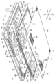
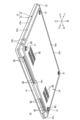
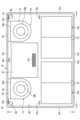
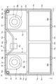
図1は、一実施形態に係る情報機器システム10を底面側から見た模式的な斜視図である。図2は、図1に示す情報機器システム10の分解斜視図である。図3は、携帯用情報機器12を底面側から見た模式的な斜視図である。本実施形態の情報機器システム10は、携帯用情報機器12と、拡張装置14とを備える。図1及び図2に示すように、情報機器システム10は携帯用情報機器12に拡張装置14を連結したドッキング状態で使用することができる。図3に示すように、情報機器システム10は拡張装置14を取り外した携帯用情報機器12を単独で使用することもできる。 Figure 1 is a schematic perspective view of an information device system 10 according to one embodiment, as viewed from the bottom side. Figure 2 is an exploded perspective view of the information device system 10 shown in Figure 1. Figure 3 is a schematic perspective view of a portable information device 12, as viewed from the bottom side. The information device system 10 of this embodiment comprises a portable information device 12 and an expansion device 14. As shown in Figures 1 and 2, the information device system 10 can be used in a docked state with the expansion device 14 connected to the portable information device 12. As shown in Figure 3, the information device system 10 can also be used with the portable information device 12 alone with the expansion device 14 removed.

先ず、携帯用情報機器12の構成例を説明する。 First, we will explain an example of the configuration of the portable information device 12.

携帯用情報機器12はクラムシェル型のノート型PCである。携帯用情報機器12は蓋体16と筐体18をヒンジ19で相対的に回動可能に連結した構成である。携帯用情報機器12はノート型PC以外、例えばタブレット型PC、スマートフォン、又は携帯用ゲーム機等でもよい。 The portable information device 12 is a clamshell-type notebook PC. The portable information device 12 has a cover 16 and a housing 18 connected by a hinge 19 so that they can rotate relative to each other. The portable information device 12 may be, other than a notebook PC, for example, a tablet PC, a smartphone, or a portable game machine.

蓋体16は薄い扁平な箱体である。蓋体16の正面にはディスプレイ20が搭載されている(図7A参照)。ディスプレイ20は、例えば有機ELディスプレイや液晶ディスプレイである。 The lid 16 is a thin, flat box. A display 20 is mounted on the front of the lid 16 (see FIG. 7A). The display 20 is, for example, an organic electroluminescence (EL) display or a liquid crystal display.

筐体18は薄い扁平な箱体である。筐体18は、筐体本体22と、カバー部材24とを有する。筐体本体22は上面22aにキーボード装置26が臨んでいる(図7A参照)。キーボード装置26は、例えばメンブレンスイッチを用いてキーキャップを物理的に上下動させる構成である。携帯用情報機器12は筐体本体22の上面22aにタッチディスプレイを設け、これにスクリーンキーボード式のキーボード装置26を表示してもよい。 The housing 18 is a thin, flat box. The housing 18 has a housing body 22 and a cover member 24. A keyboard device 26 faces the upper surface 22a of the housing body 22 (see FIG. 7A). The keyboard device 26 is configured to physically move key caps up and down using, for example, a membrane switch. The portable information device 12 may be provided with a touch display on the upper surface 22a of the housing body 22, on which the keyboard device 26 in the form of a screen keyboard is displayed.

以下、携帯用情報機器12及びこれに連結される拡張装置14の各構成要素について、筐体18の幅方向(左右)をそれぞれX1,X2方向、筐体18の奥行方向(前後)をそれぞれY1,Y2方向、筐体18の厚み方向(上下)をそれぞれZ1,Z2方向と呼んで説明する。X1,X2方向をまとめてX方向と呼ぶこともあり、Y1,Y2方向及びZ1,Z2方向についても同様にY方向、Z方向と呼ぶことがある。これら各方向は、説明の便宜上定めた方向であり、情報機器システム10の使用状態又は設置姿勢等によって変化する場合も当然にあり得る。 In the following explanation of the components of the portable information device 12 and the extension device 14 connected thereto, the width direction (left and right) of the housing 18 will be referred to as the X1 and X2 directions, the depth direction (front and back) of the housing 18 as the Y1 and Y2 directions, and the thickness direction (top and bottom) of the housing 18 as the Z1 and Z2 directions. The X1 and X2 directions are sometimes collectively referred to as the X direction, and the Y1, Y2 directions and the Z1, Z2 directions are sometimes similarly referred to as the Y direction and the Z direction. These directions are determined for the sake of convenience, and may of course change depending on the usage state or installation posture of the information device system 10.

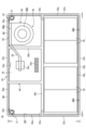
図4は、筐体本体22の模式的な底面図である。図2及び図4に示すように、筐体本体22は筐体18の上面及び四周側面を形成する。筐体本体22は底面22bの大部分が開口部28で開口している。筐体本体22は浅いバスタブ形状を有する。開口部28は拡張装置14又はカバー部材24によって着脱可能に閉じることができる(図1~図3参照)。 Figure 4 is a schematic bottom view of the housing body 22. As shown in Figures 2 and 4, the housing body 22 forms the top surface and all four side surfaces of the housing 18. Most of the bottom surface 22b of the housing body 22 is open at an opening 28. The housing body 22 has a shallow bathtub shape. The opening 28 can be removably closed by the expansion device 14 or the cover member 24 (see Figures 1 to 3).

筐体本体22は開口部28に臨むフレーム部30を有することができる。フレーム部30は、外縁部30aと、桟部30bとを有することができる。外縁部30aは筐体本体22の四周側面を形成する立壁22cの内壁に沿って枠状に延在している。桟部30bは外縁部30aの内側に格子状に配置されている。フレーム部30は底面22bよりもZ1側にオフセットして配置される(図7A参照)。フレーム部30のZ2側表面はカバー部材24又は後述する拡張筐体50の支持面となる(図7A及び図7C参照)。 The housing body 22 can have a frame portion 30 facing the opening 28. The frame portion 30 can have an outer edge portion 30a and a rib portion 30b. The outer edge portion 30a extends in a frame shape along the inner wall of the vertical wall 22c that forms the four circumferential sides of the housing body 22. The rib portions 30b are arranged in a lattice shape inside the outer edge portion 30a. The frame portion 30 is arranged offset toward the Z1 side from the bottom surface 22b (see FIG. 7A). The Z2 side surface of the frame portion 30 becomes a support surface for the cover member 24 or the expansion housing 50 described later (see FIG. 7A and FIG. 7C).

筐体本体22は底面22bから突出する一対の脚部31,31を有することができる。脚部31は底面22bのY2縁部におけるX方向両角部にそれぞれ設置されている。脚部31は携帯用情報機器12を机の上に載置する場合等に用いる脚である。脚部31は例えば先端面がゴムで形成されたゴム脚部品である。脚部31は例えば円柱状であるが、角柱状等でもよい。脚部31は、拡張装置14を連結せずに携帯用情報機器12を単独で使用する際に使用する。筐体本体22は底面22bに臨むカバー連結機構32を有するが、詳細は後述する。 The housing body 22 can have a pair of legs 31, 31 protruding from the bottom surface 22b. The legs 31 are respectively installed at both corners in the X direction at the Y2 edge of the bottom surface 22b. The legs 31 are used when placing the portable information device 12 on a desk, etc. The legs 31 are, for example, rubber leg parts whose tip surfaces are made of rubber. The legs 31 are, for example, cylindrical, but may also be rectangular or prismatic. The legs 31 are used when using the portable information device 12 alone without connecting the expansion device 14. The housing body 22 has a cover connection mechanism 32 facing the bottom surface 22b, the details of which will be described later.

筐体本体22の内部には、マザーボード34と、バッテリ装置35と、冷却モジュール36とを収容することができる。筐体本体22の内部には、さらに各種の電子部品や機械部品等を設けることができる。 The inside of the housing body 22 can accommodate a motherboard 34, a battery device 35, and a cooling module 36. Various electronic components, mechanical components, etc. can also be provided inside the housing body 22.

マザーボード34は携帯用情報機器12のメインボードとなる回路基板である。マザーボード34は例えば筐体本体22内でY2側寄りに配置され、X方向に延在している。マザーボード34はCPU(Central Processing Unit)34aを実装している。マザーボード34は、例えば左右の縁部にIOポート34bを実装している。IOポート34bとしては、USB規格やHDMI(登録商標)規格に準拠したコネクタ、LANポート等を例示できる。マザーボード34はさらにメモリや通信モジュール等も実装している。マザーボード34は、例えばZ2側表面に接続端子34cを実装していることができる。接続端子34cはZ2方向に突出した複数の端子ピンで構成されている。各端子ピンは、接続相手側である拡張装置14の接続端子62cに対する接触方向(Z2方向)に向かって常時弾性付勢されていることが好ましい。端子ピンは例えばポゴピンで構成できる。 The motherboard 34 is a circuit board that serves as the main board of the portable information device 12. For example, the motherboard 34 is disposed in the housing body 22 toward the Y2 side and extends in the X direction. The motherboard 34 is equipped with a CPU (Central Processing Unit) 34a. The motherboard 34 is equipped with IO ports 34b, for example, on the left and right edges. Examples of the IO ports 34b include connectors conforming to the USB standard or the HDMI (registered trademark) standard, and LAN ports. The motherboard 34 is also equipped with memory, a communication module, and the like. The motherboard 34 may be equipped with a connection terminal 34c, for example, on the Z2 side surface. The connection terminal 34c is composed of a plurality of terminal pins that protrude in the Z2 direction. It is preferable that each terminal pin is constantly elastically biased toward the contact direction (Z2 direction) with the connection terminal 62c of the expansion device 14, which is the connection counterpart. The terminal pin may be composed of a pogo pin, for example.

バッテリ装置35は携帯用情報機器12の電源となる充電池である。バッテリ装置35は例えばマザーボード34のY1側に並ぶように配置され、X方向に延在している。 The battery device 35 is a rechargeable battery that serves as the power source for the portable information device 12. The battery device 35 is arranged, for example, in line with the Y1 side of the motherboard 34 and extends in the X direction.

CPU34aは携帯用情報機器12に搭載された電子部品中で最大級の発熱量の発熱体である。冷却モジュール36はCPU34aが発生する熱を吸熱及び拡散し、筐体18外へと排出することができる。冷却モジュール36はCPU34a以外の発熱体を冷却することもできる。 The CPU 34a is a heat generating element that generates the largest amount of heat among the electronic components mounted on the portable information device 12. The cooling module 36 can absorb and dissipate the heat generated by the CPU 34a and expel it to the outside of the housing 18. The cooling module 36 can also cool heat generating elements other than the CPU 34a.

冷却モジュール36は、ヒートパイプ38と、ヒートシンク39と、ファン40とを有することができる。図2ではヒートパイプ38及びヒートシンク39の図示を省略している。 The cooling module 36 may have a heat pipe 38, a heat sink 39, and a fan 40. The heat pipe 38 and the heat sink 39 are not shown in FIG. 2.

ヒートパイプ38はパイプ型の熱輸送デバイスである。ヒートパイプ38は金属パイプを薄く扁平に潰して断面楕円形状に形成し、内側の密閉空間に水等の作動流体を封入した構成である。ヒートパイプ38は、一端部がCPU34aと熱的に接続され、他端がヒートシンク39と接続されている。これによりヒートパイプ38bはCPU34aの熱を高効率且つ迅速にヒートシンク39に移動させることができる。 Heat pipe 38 is a pipe-type heat transport device. Heat pipe 38 is made by crushing a metal pipe thin and flat to form an elliptical cross section, and sealing a working fluid such as water in the sealed space inside. One end of heat pipe 38 is thermally connected to CPU 34a, and the other end is connected to heat sink 39. This allows heat pipe 38b to transfer heat from CPU 34a to heat sink 39 with high efficiency and speed.

ヒートシンク39は薄い金属プレートで形成された複数枚のフィンをX方向に等間隔に並べた構造である。隣接するフィンの間にはファン40から吐出された空気が通過する隙間が形成されている。ヒートシンク39はファン40の吐出口40aに対向配置されている。 The heat sink 39 has a structure in which multiple fins made of thin metal plates are arranged at equal intervals in the X direction. A gap is formed between adjacent fins through which the air discharged from the fan 40 passes. The heat sink 39 is disposed opposite the outlet 40a of the fan 40.

ファン40は、例えばファン筐体の内部に収容したインペラをモータによって回転させる遠心ファンである。ファン40はヒートシンク39に面したY2側の側面に吐出口40aを有する。ファン40はファン筐体の下面に吸込口40bを有する。吸込口40bはファン筐体の上面にも設けることができる。ファン40は吸込口40bから筐体18外の空気を吸い込み、吐出口40aから吐き出すことができる。 The fan 40 is, for example, a centrifugal fan in which an impeller housed inside the fan housing is rotated by a motor. The fan 40 has an outlet 40a on the side facing the heat sink 39 on the Y2 side. The fan 40 has an inlet 40b on the bottom surface of the fan housing. The inlet 40b can also be provided on the top surface of the fan housing. The fan 40 can draw in air outside the housing 18 through the inlet 40b and expel it from the outlet 40a.

筐体本体22はY2側の立壁22cに通気口42を有することができる。通気口42は、吐出口40aから吐出されてヒートシンク39を通過した空気(排気)を筐体18外に排出するための開口である。通気口42は立壁22cの長手方向に沿って並列された複数の小窓で形成することができる。通気口42は、例えば立壁22cの長手方向で中央付近からX1側端部に亘って形成されている。この立壁22cには補助通気口43が形成することができる。補助通気口43はY2側の立壁22cに形成された複数の小窓で形成することができる。補助通気口43は、例えば立壁22cの長手方向でX2側に寄った位置に形成されている。補助通気口43は、後述する拡張装置14のX2側のファン70の空気を排出するための開口である。補助通気口43は省略されてもよい。 The housing body 22 may have a vent 42 in the vertical wall 22c on the Y2 side. The vent 42 is an opening for discharging the air (exhaust air) discharged from the discharge port 40a and passing through the heat sink 39 to the outside of the housing 18. The vent 42 may be formed of a plurality of small windows arranged in parallel along the longitudinal direction of the vertical wall 22c. The vent 42 is formed, for example, from near the center to the X1 side end in the longitudinal direction of the vertical wall 22c. An auxiliary vent 43 may be formed in this vertical wall 22c. The auxiliary vent 43 may be formed of a plurality of small windows formed in the vertical wall 22c on the Y2 side. The auxiliary vent 43 is formed, for example, at a position closer to the X2 side in the longitudinal direction of the vertical wall 22c. The auxiliary vent 43 is an opening for discharging air from the fan 70 on the X2 side of the expansion device 14 described later. The auxiliary vent 43 may be omitted.

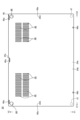
図5は、カバー部材24の平面図である。図5はカバー部材24を筐体本体22の底面20bに対向配置される内面24b側から見た図である。図1~図3及び図5に示すように、カバー部材24は略矩形の薄いプレートで形成することができる。カバー部材24は筐体本体22の底面22bの開口部28を着脱可能に閉じることができる(図3参照)。カバー部材24は後述する拡張筐体50の底面50bの開口部53を着脱可能に閉じることもできる(図1参照)。 Figure 5 is a plan view of the cover member 24. Figure 5 is a view of the cover member 24 as seen from the inner surface 24b side that is disposed opposite the bottom surface 20b of the housing main body 22. As shown in Figures 1 to 3 and 5, the cover member 24 can be formed of a thin plate that is approximately rectangular. The cover member 24 can detachably close the opening 28 on the bottom surface 22b of the housing main body 22 (see Figure 3). The cover member 24 can also detachably close the opening 53 on the bottom surface 50b of the expansion housing 50 described below (see Figure 1).

カバー部材24は、一対の孔部44,44と、一対の底面通気口45,46と、一対の脚部47,47とを有することができる。 The cover member 24 can have a pair of holes 44, 44, a pair of bottom vents 45, 46, and a pair of legs 47, 47.

孔部44はカバー部材24のY2側縁部におけるX方向両角部にそれぞれ形成された貫通孔である。各孔部44はそれぞれ平面視で各脚部31と上下にオーバーラップする位置にある。孔部44は携帯用情報機器12の脚部31を挿通可能な内径を有する。孔部44は脚部31をXY方向に位置決めできることが好ましい。従って孔部44の内径は脚部31の外径より僅かに大きい程度であることが好ましい。孔部44は後述する拡張装置14の拡張脚部56も脚部31と同様に挿通可能である。孔部44は拡張脚部56もXY方向に位置決めできることが好ましい(図1及び図2参照)。 The holes 44 are through holes formed at both corners in the X direction at the Y2 side edge of the cover member 24. Each hole 44 is located so as to overlap each leg 31 vertically in a plan view. The holes 44 have an inner diameter that allows the leg 31 of the portable information device 12 to be inserted therethrough. It is preferable that the hole 44 can position the leg 31 in the XY direction. Therefore, it is preferable that the inner diameter of the hole 44 is slightly larger than the outer diameter of the leg 31. The hole 44 can also be inserted with the expansion leg 56 of the expansion device 14 described later, in the same way as the leg 31. It is preferable that the hole 44 can also position the expansion leg 56 in the XY direction (see Figures 1 and 2).

底面通気口45,46は、それぞれ複数本のスリット状の孔部を並列して構成することができる。X1側の底面通気口45は平面視でファン40と上下にオーバーラップする位置にある。底面通気口45の配置は、平面視で後述する拡張装置14の一方のファン70と上下にオーバーラップする位置でもある。X2側の底面通気口46は、平面視で後述する拡張装置14の他方のファン70と上下にオーバーラップする位置にある。底面通気口45,46は、各ファン40,70の吸込口40b,70bに外気を導入するための吸気口となる。 The bottom vents 45, 46 can each be configured with multiple slit-shaped holes arranged in parallel. The bottom vent 45 on the X1 side is positioned so as to overlap vertically with the fan 40 in a plan view. The arrangement of the bottom vent 45 is also positioned so as to overlap vertically with one fan 70 of the expansion device 14, which will be described later, in a plan view. The bottom vent 46 on the X2 side is positioned so as to overlap vertically with the other fan 70 of the expansion device 14, which will be described later, in a plan view. The bottom vents 45, 46 serve as intakes for introducing outside air into the intakes 40b, 70b of the fans 40, 70.

本実施形態の場合、ファン40に対応する一方の底面通気口45は、その開口面積が他方の底面通気口46の開口面積よりも大きい。これによりカバー部材24が携帯用情報機器12に装着されているか又は拡張装置14に装着されているか否かに関わらず、底面通気口45は十分な外気の導入量を確保できる。一方で、底面通気口46は実質的に拡張装置14にカバー部材24を装着した場合にのみ利用される。このため底面通気口46は携帯用情報機器12の外観上で目立つことを避けるため、その開口面積を小さくしている。 In the present embodiment, the opening area of one bottom vent 45 corresponding to the fan 40 is larger than the opening area of the other bottom vent 46. This allows the bottom vent 45 to ensure a sufficient amount of outside air is introduced regardless of whether the cover member 24 is attached to the portable information device 12 or the expansion device 14. On the other hand, the bottom vent 46 is actually only used when the cover member 24 is attached to the expansion device 14. For this reason, the opening area of the bottom vent 46 is made small to avoid it being noticeable on the exterior of the portable information device 12.

脚部47はカバー部材24の外面24aから突出している。脚部47は、例えば外面24aのY1側縁部におけるX方向両角部にそれぞれ設置されている。脚部47は図1に示す情報機器システム10又は図3に示す携帯用情報機器12を机の上に載置する場合等に用いる脚である。脚部47は上記した脚部31と同様に先端面がゴムで形成されたゴム脚部品で構成できる。カバー部材24は内面24bに臨む連結機構48を有するが、詳細は後述する。 The legs 47 protrude from the outer surface 24a of the cover member 24. The legs 47 are installed, for example, at both corners in the X direction at the Y1 side edge of the outer surface 24a. The legs 47 are used when placing the information device system 10 shown in FIG. 1 or the portable information device 12 shown in FIG. 3 on a desk, etc. The legs 47 can be made of rubber leg parts whose tip surfaces are made of rubber, similar to the legs 31 described above. The cover member 24 has a connecting mechanism 48 facing the inner surface 24b, which will be described in detail later.

次に、拡張装置14の構成例を説明する。 Next, we will explain an example configuration of the expansion device 14.

図6Aは、拡張装置14の模式的な平面図である。図6Bは、拡張装置14の模式的な底面図である。図1、図2、図6A及び図6Bに示すように、拡張装置14は、携帯用情報機器12に連結され、その機能を拡張するドックである。 Figure 6A is a schematic plan view of the expansion device 14. Figure 6B is a schematic bottom view of the expansion device 14. As shown in Figures 1, 2, 6A, and 6B, the expansion device 14 is a dock that is connected to the portable information device 12 and expands its functions.

拡張装置14は拡張筐体50を備える。拡張筐体50は薄い扁平な箱体である。拡張筐体50の上面50aは携帯用情報機器12の底面22bに対する連結面となる。拡張筐体50の底面50bはカバー部材24の連結面となる。拡張筐体50は、上面50a及び底面50bの大部分がそれぞれ開口部52,53で開口している。拡張筐体50の四周側面は立壁50cで形成されている。開口部52,53は立壁50cの内側にそれぞれ形成されている。 The expansion device 14 includes an expansion housing 50. The expansion housing 50 is a thin, flat box. The top surface 50a of the expansion housing 50 is the connecting surface for the bottom surface 22b of the portable information device 12. The bottom surface 50b of the expansion housing 50 is the connecting surface for the cover member 24. Most of the top surface 50a and the bottom surface 50b of the expansion housing 50 are open at openings 52, 53, respectively. The four side surfaces of the expansion housing 50 are formed by vertical walls 50c. The openings 52, 53 are each formed inside the vertical walls 50c.

拡張筐体50は、一対の穴部54,54と、一対の拡張脚部56,56とを有することができる。 The expansion housing 50 can have a pair of holes 54, 54 and a pair of expansion legs 56, 56.

穴部54は拡張筐体50のY2側縁部におけるX方向両角部にそれぞれ形成されている。穴部54は上面50aに臨んで開口したZ方向の穴である(図6A及び図7B参照)。穴部54は携帯用情報機器12の脚部31を挿入可能な内径及び深さを有する。穴部54は脚部31を位置決めして挿入できることが好ましい。従って穴部54の内径は脚部31の外径より僅かに大きい程度であることが好ましい。穴部54はZ方向の貫通穴でもよい。拡張筐体50は上面50aに臨む連結機構58を有するが、詳細は後述する。 The holes 54 are formed at both corners in the X direction on the Y2 side edge of the expansion housing 50. The holes 54 are Z direction holes that open to the top surface 50a (see Figures 6A and 7B). The holes 54 have an inner diameter and depth that allow the legs 31 of the portable information device 12 to be inserted. It is preferable that the holes 54 allow the legs 31 to be inserted after positioning them. Therefore, it is preferable that the inner diameter of the holes 54 is slightly larger than the outer diameter of the legs 31. The holes 54 may be through holes in the Z direction. The expansion housing 50 has a connection mechanism 58 that faces the top surface 50a, which will be described in detail later.

拡張脚部56は底面50bのY2側縁部におけるX方向両角部にそれぞれ設置されている。拡張脚部56は携帯用情報機器12に拡張装置14を連結した情報機器システム10を机の上に載置する場合等の脚となるものである。拡張脚部56は上記した脚部31と同様に先端面がゴムで形成されたゴム脚部品で構成できる。拡張筐体50は底面50bに臨むカバー連結機構60を有するが、詳細は後述する。 The extension legs 56 are installed at both corners in the X direction on the Y2 side edge of the bottom surface 50b. The extension legs 56 serve as legs when the information device system 10, in which the extension device 14 is connected to the portable information device 12, is placed on a desk, etc. The extension legs 56 can be made of rubber foot parts whose tip surfaces are made of rubber, similar to the legs 31 described above. The extension housing 50 has a cover connection mechanism 60 facing the bottom surface 50b, which will be described in detail later.

拡張筐体50の内部には、拡張ボード62と、拡張バッテリ装置63と、拡張冷却モジュール64とを収納することができる。拡張筐体50の内部には、さらに各種の電子部品や機械部品等を設けることができる。 The expansion enclosure 50 can house an expansion board 62, an extended battery device 63, and an extended cooling module 64. Various electronic and mechanical components can also be provided inside the expansion enclosure 50.

拡張ボード62は携帯用情報機器12のマザーボード34の機能拡張用のサブボードとなる回路基板である。拡張ボード62は例えば拡張筐体50内でY2側寄りに配置されている。拡張ボード62は、例えばdGPU(dedicated Graphics Processing Unit)62aを実装し、携帯用情報機器12のグラフィック性能を強化することができる。拡張ボード62は、例えば左右の縁部にIOポート62bを実装している。IOポート62bは、上記した携帯用情報機器12のIOポート34bと同一又は異なる種類の規格に準拠したコネクタ等を例示できる。拡張ボード62は、例えばZ1側表面に接続端子62cを実装していることができる。接続端子62cは携帯用情報機器12の接続端子34cと上下にオーバーラップする位置にある。接続端子62cは、例えばポゴピンで形成された接続端子34cを接続可能な導電パッドで構成することができる。 The expansion board 62 is a circuit board that serves as a sub-board for expanding the functions of the motherboard 34 of the portable information device 12. The expansion board 62 is disposed, for example, on the Y2 side in the expansion housing 50. The expansion board 62 can be equipped with, for example, a dGPU (dedicated graphics processing unit) 62a to enhance the graphic performance of the portable information device 12. The expansion board 62 is equipped with IO ports 62b, for example, on the left and right edges. The IO port 62b can be, for example, a connector conforming to the same or different type of standard as the IO port 34b of the portable information device 12 described above. The expansion board 62 can be equipped with a connection terminal 62c, for example, on the Z1 side surface. The connection terminal 62c is located in a position that overlaps vertically with the connection terminal 34c of the portable information device 12. The connection terminal 62c can be configured as a conductive pad to which the connection terminal 34c formed by a pogo pin can be connected.

拡張バッテリ装置63は携帯用情報機器12の外部電源となる充電池である。拡張バッテリ装置63はバッテリ装置35を補完して携帯用情報機器12の駆動時間を延長することができる。拡張バッテリ装置63は例えば拡張ボード62のY1側に並ぶように配置され、X方向に延在している。 The extended battery device 63 is a rechargeable battery that serves as an external power source for the portable information device 12. The extended battery device 63 complements the battery device 35 and can extend the operating time of the portable information device 12. The extended battery device 63 is arranged, for example, next to the Y1 side of the extension board 62 and extends in the X direction.

dGPU62aは拡張装置14に搭載された電子部品中で最大級の発熱量の発熱体である。拡張冷却モジュール64はdGPU62aが発生する熱を吸熱及び拡散し、拡張筐体50外へと排出することができる。拡張冷却モジュール64は携帯用情報機器12の筐体18内も同時に冷却することができる。 The dGPU 62a is the heat generating element with the largest heat output among the electronic components mounted on the expansion device 14. The expansion cooling module 64 can absorb and disperse the heat generated by the dGPU 62a and discharge it outside the expansion housing 50. The expansion cooling module 64 can also simultaneously cool the inside of the housing 18 of the portable information device 12.

拡張冷却モジュール64は、ヒートパイプ68と、一対のヒートシンク69,69と、一対のファン70,70とを有することができる。図2ではヒートパイプ68及びヒートシンク69の図示を省略している。 The expansion cooling module 64 can have a heat pipe 68, a pair of heat sinks 69, 69, and a pair of fans 70, 70. The heat pipe 68 and the heat sink 69 are not shown in FIG. 2.

ヒートパイプ68、ヒートシンク69及びファン70は、それぞれ携帯用情報機器12に搭載したヒートパイプ38、ヒートシンク39及びファン40と同一又は同様な構成とすることができるため、詳細な説明は省略する。ヒートパイプ68は中央付近がdGPU62aと熱的に接続され、両端が左右のヒートシンク69,69と接続されている。各ファン70は、それぞれファン40の吐出口40a及び吸込口40bと同様な吐出口70a及び吸込口70bを有する。 The heat pipe 68, heat sink 69, and fan 70 can be configured the same as or similar to the heat pipe 38, heat sink 39, and fan 40 mounted on the portable information device 12, and detailed description will be omitted. The heat pipe 68 is thermally connected to the dGPU 62a near the center, and both ends are connected to the left and right heat sinks 69, 69. Each fan 70 has an outlet 70a and an inlet 70b similar to the outlet 40a and inlet 40b of the fan 40, respectively.

拡張筐体50はY2側の立壁50cに通気口72を有することができる。通気口72は、左右の吐出口70aからそれぞれ吐出されて左右のヒートシンク69を通過した空気(排気)を拡張筐体50外に排出するための開口である。図1及び図2に示すように、通気口72は立壁50cの長手方向に沿って並列された複数の小窓で形成することができる。通気口72は立壁50cの略全長に亘って延在している。 The expansion housing 50 can have an air vent 72 in the vertical wall 50c on the Y2 side. The air vent 72 is an opening for discharging air (exhaust air) discharged from the left and right exhaust ports 70a and passing through the left and right heat sinks 69 to the outside of the expansion housing 50. As shown in Figures 1 and 2, the air vent 72 can be formed of multiple small windows arranged in parallel along the longitudinal direction of the vertical wall 50c. The air vent 72 extends over substantially the entire length of the vertical wall 50c.

図2及び図6Bに示すように、拡張筐体50は底面50bの開口部53に臨むフレーム部74を有することができる。フレーム部74は、携帯用情報機器12のフレーム部30を構成する外縁部30a及び桟部30bと同様な外縁部74a及び桟部74bを有する構成とすることができるため、詳細な説明は省略する。フレーム部74も底面50bよりもZ1側にオフセットして配置される(図7B参照)。フレーム部74のZ2側表面はカバー部材24の支持面となる(図7C参照)。拡張筐体50は上面50aの開口部52に臨む部分にもフレーム部74と同様な構成を設けることができる。 2 and 6B, the expansion housing 50 can have a frame portion 74 facing the opening 53 of the bottom surface 50b. The frame portion 74 can have an outer edge portion 74a and a crosspiece portion 74b similar to the outer edge portion 30a and crosspiece portion 30b that constitute the frame portion 30 of the portable information device 12, so a detailed description will be omitted. The frame portion 74 is also positioned offset toward the Z1 side from the bottom surface 50b (see FIG. 7B). The Z2 side surface of the frame portion 74 becomes the support surface of the cover member 24 (see FIG. 7C). The expansion housing 50 can also have a configuration similar to the frame portion 74 in the portion facing the opening 52 of the top surface 50a.

次に、携帯用情報機器12に対する拡張装置14の連結構造及び連結動作を説明する。 Next, we will explain the connection structure and connection operation of the expansion device 14 to the portable information device 12.

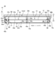
図7Aは、携帯用情報機器12の模式的な側面断面図である。図7Bは、図7Aに示す携帯用情報機器12からカバー部材24を取り外して拡張装置14を連結する動作を示す側面断面図である。図7Cは、図7Bに示す携帯用情報機器12に拡張装置14を連結した情報機器システム10の側面断面図である。 Figure 7A is a schematic side cross-sectional view of the portable information device 12. Figure 7B is a side cross-sectional view showing the operation of removing the cover member 24 from the portable information device 12 shown in Figure 7A and connecting the expansion device 14. Figure 7C is a side cross-sectional view of the information device system 10 in which the expansion device 14 is connected to the portable information device 12 shown in Figure 7B.

図4及び図7Bに示すように、携帯用情報機器12の筐体本体22は底面22b側にカバー連結機構(第1カバー連結機構)32を備える。カバー連結機構32は、複数の磁石32aと、複数の係合穴32bとを有することができる。磁石32aは、例えばY2側の立壁20cに沿う外縁部30aにX方向で3つ設けられる。磁石32aは、例えばX方向に延びる桟部30bの両端付近にそれぞれ設けられる。磁石32aは外縁部30a及び桟部30bに埋設され、開口部28から底面22b側を臨んでいる。係合穴32bは、例えばY1側の立壁20cの内壁に左右一対で設けられ、Y2方向を向いて開口している。磁石32aは一部又は全部をねじで代用することもでき、他の磁石48a,58a,60aも同様である。 As shown in FIG. 4 and FIG. 7B, the housing body 22 of the portable information device 12 has a cover connection mechanism (first cover connection mechanism) 32 on the bottom surface 22b side. The cover connection mechanism 32 can have multiple magnets 32a and multiple engagement holes 32b. For example, three magnets 32a are provided in the X direction on the outer edge portion 30a along the vertical wall 20c on the Y2 side. For example, the magnets 32a are provided near both ends of the crosspiece portion 30b extending in the X direction. The magnets 32a are embedded in the outer edge portion 30a and the crosspiece portion 30b, and face the bottom surface 22b side from the opening portion 28. The engagement holes 32b are provided in a pair on the left and right sides on the inner wall of the vertical wall 20c on the Y1 side, and open toward the Y2 direction. The magnets 32a can be partially or entirely replaced with screws, and the same is true for the other magnets 48a, 58a, and 60a.

図5及び図7Bに示すように、カバー部材24は内面24b側に連結機構(第1連結機構)48を備える。連結機構48は、複数の磁石48aと、複数のフック48bとを有することができる。各磁石48aは、筐体本体22の各磁石32aと吸着可能な位置に配置されている。つまり各磁石48aはカバー部材24を筐体本体22に位置決めした際、各磁石32aと上下に対向する位置にある。磁石48aはカバー部材24に埋設され、内面24b側を臨んでいる。各フック48bは、筐体本体22の各係合穴32bと係合可能な位置に配置されている。つまり各フック48bはカバー部材24を筐体本体22に位置決めした際、各係合穴32bと係脱可能な位置にある。フック48bはカバー部材24の内面24bから突出するように設けられている。 5 and 7B, the cover member 24 has a coupling mechanism (first coupling mechanism) 48 on the inner surface 24b side. The coupling mechanism 48 can have a plurality of magnets 48a and a plurality of hooks 48b. Each magnet 48a is arranged at a position where it can be attracted to each magnet 32a of the housing body 22. That is, when the cover member 24 is positioned on the housing body 22, each magnet 48a is located in a position facing each magnet 32a vertically. The magnet 48a is embedded in the cover member 24 and faces the inner surface 24b. Each hook 48b is arranged at a position where it can be engaged with each engagement hole 32b of the housing body 22. That is, when the cover member 24 is positioned on the housing body 22, each hook 48b is located at a position where it can be engaged with and disengaged from each engagement hole 32b. The hooks 48b are provided to protrude from the inner surface 24b of the cover member 24.

図6A及び図7Bに示すように、拡張装置14の拡張筐体50は上面50a側に連結機構(第2連結機構)58を備える。連結機構58は、複数の磁石58aと、複数のフック58bとを有することができる。各磁石58aは、筐体本体22の各磁石32aと吸着可能な位置に配置されている。つまり各磁石58aは拡張筐体50を筐体本体22に位置決めした際、各磁石32aと上下に対向する位置にある。磁石58aは拡張筐体50に埋設され、開口部52から上面50a側を臨んでいる。各フック58bは、筐体本体22の各係合穴32bと係合可能な位置に配置されている。つまり各フック58bは拡張筐体50を筐体本体22に位置決めした際、各係合穴32bと係脱可能な位置にある。フック58bは上面50aから突出するように設けられている。 As shown in FIG. 6A and FIG. 7B, the expansion housing 50 of the expansion device 14 has a coupling mechanism (second coupling mechanism) 58 on the upper surface 50a side. The coupling mechanism 58 can have multiple magnets 58a and multiple hooks 58b. Each magnet 58a is arranged at a position where it can be attracted to each magnet 32a of the housing body 22. In other words, when the expansion housing 50 is positioned on the housing body 22, each magnet 58a is located in a position facing each magnet 32a vertically. The magnet 58a is embedded in the expansion housing 50 and faces the upper surface 50a side from the opening 52. Each hook 58b is arranged at a position where it can engage with each engagement hole 32b of the housing body 22. In other words, when the expansion housing 50 is positioned on the housing body 22, each hook 58b is located at a position where it can be engaged with and disengaged from each engagement hole 32b. The hooks 58b are provided to protrude from the upper surface 50a.

図6B及び図7Bに示すように、拡張装置14の拡張筐体50は底面50b側にカバー連結機構(第2カバー連結機構)60を備える。カバー連結機構60は、複数の磁石60aと、複数の係合穴60bとを有することができる。磁石60aは、カバー部材24を拡張筐体50に位置決めした際、各磁石48aと上下に対向する位置にある。磁石60aは、外縁部74a及び桟部74bに埋設され、開口部53から底面50b側を臨んでいる。係合穴60bは、例えばY2側の立壁50cの内壁に左右一対で設けられ、Y2方向を向いて開口している。各係合穴60bは、カバー部材24を拡張筐体50に位置決めした際、各フック48bを係合可能な位置に配置されている。 As shown in FIG. 6B and FIG. 7B, the expansion housing 50 of the expansion device 14 has a cover connection mechanism (second cover connection mechanism) 60 on the bottom surface 50b side. The cover connection mechanism 60 can have multiple magnets 60a and multiple engagement holes 60b. When the cover member 24 is positioned in the expansion housing 50, the magnets 60a are positioned to face each magnet 48a vertically. The magnets 60a are embedded in the outer edge portion 74a and the crosspiece portion 74b, and face the bottom surface 50b side from the opening 53. The engagement holes 60b are provided in a pair on the left and right sides, for example, on the inner wall of the vertical wall 50c on the Y2 side, and open toward the Y2 direction. Each engagement hole 60b is positioned so that each hook 48b can be engaged when the cover member 24 is positioned in the expansion housing 50.

次に、携帯用情報機器12に対する拡張装置14の連結動作を説明する。 Next, we will explain how to connect the expansion device 14 to the portable information device 12.

図3及び図7Aに示すように、携帯用情報機器12は、拡張装置14を連結しない場合は底面22bの開口部28をカバー部材24で閉じることができる。カバー部材24は、連結機構48をカバー連結機構32に連結することで筐体本体22に着脱可能に連結できる。カバー部材24は、各磁石48aが各磁石32aに吸着し、各フック48bが各係合穴32bに係合する。この際、カバー部材24の孔部44には底面22bから突出する脚部31が挿通される。これによりカバー部材24はがたつきなく安定して筐体本体22に連結される。特に孔部44が脚部31の位置決め機能を有すると、カバー部材24の筐体本体22に対する連結時の位置合わせが容易となる。さらにカバー部材24が筐体本体22に連結された状態での位置ずれが一層確実に抑制される。このように拡張装置14を連結しない携帯用情報機器12は薄型且つ軽量である。 3 and 7A, when the extension device 14 is not connected, the opening 28 of the bottom surface 22b of the portable information device 12 can be closed by the cover member 24. The cover member 24 can be detachably connected to the housing body 22 by connecting the connection mechanism 48 to the cover connection mechanism 32. In the cover member 24, each magnet 48a is attracted to each magnet 32a, and each hook 48b is engaged with each engagement hole 32b. At this time, the leg portion 31 protruding from the bottom surface 22b is inserted into the hole portion 44 of the cover member 24. As a result, the cover member 24 is stably connected to the housing body 22 without rattling. In particular, if the hole portion 44 has a positioning function for the leg portion 31, it becomes easy to align the cover member 24 with the housing body 22 when it is connected. Furthermore, the positional deviation when the cover member 24 is connected to the housing body 22 is more reliably suppressed. In this way, the portable information device 12 without the extension device 14 is thin and lightweight.

図2及び図7Bに示すように、携帯用情報機器12に拡張装置14を連結する場合は、先ずカバー部材24を取り外す。カバー部材24は、例えばY2側縁部を指先や工具でZ2側に持ち上げて磁石48aを磁石32aから引き剥がす。続いてカバー部材24をY2方向にスライドさせる。これによりフック48bが係合穴32bから抜去され、カバー部材24を筐体本体22から容易に取り外すことができる。図1~図3及び図5に示すように、カバー部材24はY2側縁部の中央部に切欠形状部24cを設けておくこともできる。そうするとカバー部材24は筐体本体22から持ち上げる際、一層容易に指先や工具を引っ掛けることができる。 As shown in Figures 2 and 7B, when connecting the expansion device 14 to the portable information device 12, first remove the cover member 24. For example, the Y2 side edge of the cover member 24 is lifted toward the Z2 side with a fingertip or a tool, and the magnet 48a is pulled off from the magnet 32a. The cover member 24 is then slid in the Y2 direction. This removes the hook 48b from the engagement hole 32b, and the cover member 24 can be easily removed from the housing body 22. As shown in Figures 1 to 3 and 5, the cover member 24 can also be provided with a notched portion 24c in the center of the Y2 side edge. This makes it easier to hook a fingertip or a tool onto the cover member 24 when lifting it from the housing body 22.

図2及び図7Bに示すように、筐体本体22はカバー部材24が取り外されると底面22bに開口部28が露出する。そこで、次に拡張装置14を携帯用情報機器12に連結する。拡張装置14は、連結機構58をカバー連結機構32に連結することで筐体本体22に着脱可能に連結できる。この連結は、先ず拡張筐体50のY2側縁部をZ2側に持ち上げた姿勢とし、各フック58bを筐体本体22の各係合穴32bに係合させる。続いて拡張筐体50をZ1側に移動させ、各磁石58aを各磁石32aに吸着させる。同時に、筐体本体22の底面22bから突出する脚部31を拡張筐体50の上面50aで開口する穴部54に挿入する。これにより拡張装置14はがたつきなく安定して筐体本体22に連結される(図7C参照)。特に穴部54が脚部31の位置決め機能を有すると、拡張装置14の筐体本体22に対する連結時の位置合わせが容易となる。さらに拡張装置14が筐体本体22に連結された状態での位置ずれが一層確実に抑制される。 2 and 7B, when the cover member 24 of the housing body 22 is removed, the opening 28 is exposed on the bottom surface 22b. Next, the expansion device 14 is connected to the portable information device 12. The expansion device 14 can be detachably connected to the housing body 22 by connecting the connection mechanism 58 to the cover connection mechanism 32. This connection is first performed by lifting the Y2 side edge of the expansion housing 50 to the Z2 side, and engaging each hook 58b with each engagement hole 32b of the housing body 22. Next, the expansion housing 50 is moved to the Z1 side, and each magnet 58a is attracted to each magnet 32a. At the same time, the leg 31 protruding from the bottom surface 22b of the housing body 22 is inserted into the hole 54 opening on the top surface 50a of the expansion housing 50. This allows the expansion device 14 to be stably connected to the housing body 22 without any rattling (see FIG. 7C). In particular, if the holes 54 have a positioning function for the legs 31, it becomes easier to align the expansion device 14 when connecting it to the housing body 22. Furthermore, misalignment of the expansion device 14 when connected to the housing body 22 is more reliably suppressed.

なお、拡張装置14が筐体本体22に連結されると、接続端子34cと接続端子62cが互いに接続される。これより情報機器システム10は携帯用情報機器12と拡張装置14とが電気的に接続され、有線での情報の送受信が可能となる。なお、携帯用情報機器12及び拡張装置14は接続端子34c,62cを省略し、互いに無線で接続される構成とすることもできる。この場合の無線通信規格は、Bluetooth(登録商標)又は無線LAN等を例示できる。 When the expansion device 14 is connected to the housing body 22, the connection terminal 34c and the connection terminal 62c are connected to each other. This electrically connects the portable information device 12 and the expansion device 14 in the information device system 10, enabling wired information transmission and reception. The portable information device 12 and the expansion device 14 can also be configured to omit the connection terminals 34c, 62c and be connected to each other wirelessly. Examples of wireless communication standards in this case include Bluetooth (registered trademark) or wireless LAN.

続いて、拡張装置14の底面50bにカバー部材24を装着する。カバー部材24は、連結機構48をカバー連結機構60に連結することで拡張筐体50に着脱可能に連結できる。なお、カバー部材24は拡張装置14を携帯用情報機器12に連結する前に底面50bに装着してもよい。この連結は、先ずカバー部材24のY2側縁部をZ2側に持ち上げた姿勢とし、各フック48bを拡張筐体50の各係合穴60bに係合させる。続いてカバー部材24をZ1側に移動させ、各磁石48aを各磁石60aに吸着させる。同時に、拡張筐体50の底面50bから突出する拡張脚部56を孔部44に挿通させる。これによりカバー部材24はがたつきなく安定して拡張筐体50に連結される(図7C参照)。特に孔部44が拡張脚部56の位置決め機能を有すると、カバー部材24の拡張筐体50に対する連結時の位置合わせが容易となる。さらにカバー部材24が拡張筐体50に連結された状態での位置ずれが一層確実に抑制される。このように拡張装置14を携帯用情報機器12に連結した情報機器システム10は、携帯用情報機器12のパフォーマンスを拡張装置14で向上させることができる。 Next, the cover member 24 is attached to the bottom surface 50b of the expansion unit 14. The cover member 24 can be detachably connected to the expansion housing 50 by connecting the connection mechanism 48 to the cover connection mechanism 60. The cover member 24 may be attached to the bottom surface 50b before connecting the expansion unit 14 to the portable information device 12. This connection is first performed by lifting the Y2 side edge of the cover member 24 to the Z2 side, and engaging each hook 48b with each engagement hole 60b of the expansion housing 50. Next, the cover member 24 is moved to the Z1 side, and each magnet 48a is attracted to each magnet 60a. At the same time, the expansion leg portion 56 protruding from the bottom surface 50b of the expansion housing 50 is inserted into the hole portion 44. As a result, the cover member 24 is stably connected to the expansion housing 50 without rattling (see FIG. 7C). In particular, when the holes 44 have a positioning function for the expansion legs 56, it becomes easier to align the cover member 24 when it is connected to the expansion housing 50. Furthermore, misalignment of the cover member 24 when it is connected to the expansion housing 50 is more reliably suppressed. In this way, the information device system 10 in which the expansion device 14 is connected to the portable information device 12 can improve the performance of the portable information device 12 with the expansion device 14.

以上のように、本実施形態に係る情報機器システム10は、携帯用情報機器12と、携帯用情報機器12に着脱可能に連結される拡張装置14とを備える。携帯用情報機器12は、底面22bが開口した筐体本体22と、筐体本体22の底面22b側に設けられたカバー連結機構32と、カバー連結機構32に連結機構48で着脱されて底面22bを閉じるカバー部材24と、を有する。拡張装置14は、上面50aが開口した拡張筐体50と、拡張筐体50の上面50a側に設けられ、カバー部材24が取り外された筐体本体22のカバー連結機構32に着脱されることで拡張装置14を携帯用情報機器12に連結する連結機構58と、を有する。 As described above, the information device system 10 according to this embodiment includes a portable information device 12 and an expansion device 14 that is detachably connected to the portable information device 12. The portable information device 12 includes a housing body 22 with an open bottom surface 22b, a cover connection mechanism 32 provided on the bottom surface 22b side of the housing body 22, and a cover member 24 that is attached and detached to the cover connection mechanism 32 by a connection mechanism 48 to close the bottom surface 22b. The expansion device 14 includes an expansion housing 50 with an open top surface 50a, and a connection mechanism 58 provided on the top surface 50a side of the expansion housing 50, which is attached and detached to the cover connection mechanism 32 of the housing body 22 from which the cover member 24 has been removed, thereby connecting the expansion device 14 to the portable information device 12.

このような情報機器システム10は、カバー部材24を取り外した携帯用情報機器12の筐体18に対して拡張装置14を連結する。この際、拡張装置14の連結機構58は、カバー部材24を筐体本体22に連結していたカバー連結機構32を利用して携帯用情報機器12に連結する。つまり情報機器システム10は、底面22bから取り外したカバー部材24に代えて拡張装置14を携帯用情報機器12に連結する。このため拡張装置14は携帯用情報機器12に一体的に連結することができる。その結果、情報機器システム10は拡張装置14をドッキングした携帯用情報機器12を容易に持ち運びすることができ、例えば外出先等でのモバイル使用にそのまま対応できる。このため情報機器システム10は、モバイル使用時にも拡張装置14の拡張機能を利用した高いパフォーマンスを得ることができる。 In such an information device system 10, the expansion device 14 is connected to the housing 18 of the portable information device 12 from which the cover member 24 has been removed. At this time, the connection mechanism 58 of the expansion device 14 is connected to the portable information device 12 using the cover connection mechanism 32 that connected the cover member 24 to the housing body 22. In other words, the information device system 10 connects the expansion device 14 to the portable information device 12 in place of the cover member 24 removed from the bottom surface 22b. Therefore, the expansion device 14 can be connected integrally to the portable information device 12. As a result, the information device system 10 can easily carry the portable information device 12 with the expansion device 14 docked thereto, and can be used on the go, for example. Therefore, the information device system 10 can obtain high performance by utilizing the expansion function of the expansion device 14 even when used on the go.

情報機器システム10は、拡張装置14を取り外すことで携帯用情報機器12の小型化及び軽量化を図ることができる。つまり携帯用情報機器12は拡張装置14による性能向上を前提として、携帯用情報機器12自身に搭載する機能を必要最小限に抑えることもできる。これにより携帯用情報機器12の単独使用時のさらなる薄型化及び軽量化が可能となる。このように情報機器システム10は、ユーザの用途や目的に応じて携帯用情報機器12のパフォーマンスや大きさを容易に選択することができる。このため情報機器システム10は携帯用情報機器12の汎用性を向上させることができる。その結果、ユーザはより柔軟な使用方法を選択することができる。さらに携帯用情報機器12は例えば拡張装置14を交換することでパフォーマンスのアップデートを図ることができ、製品寿命の延長も可能となる。 The information device system 10 can reduce the size and weight of the portable information device 12 by removing the expansion device 14. In other words, the portable information device 12 can minimize the functions installed in the portable information device 12 itself, assuming that the expansion device 14 will improve its performance. This allows the portable information device 12 to be made even thinner and lighter when used alone. In this way, the information device system 10 can easily select the performance and size of the portable information device 12 according to the user's use and purpose. Therefore, the information device system 10 can improve the versatility of the portable information device 12. As a result, the user can select a more flexible method of use. Furthermore, the performance of the portable information device 12 can be updated by replacing the expansion device 14, for example, and the product life can be extended.

特に拡張装置14はカバー部材24を取り外して開口部28を露出させた筐体本体22に連結する。このため情報機器システム10は、拡張装置14が搭載する拡張冷却モジュール64で携帯用情報機器12の筐体18内を直接的に冷却することができる。その結果、携帯用情報機器12は拡張装置14によって冷却性能が大幅に向上するため、パフォーマンスが一層向上する。 In particular, the expansion device 14 is connected to the housing body 22 with the cover member 24 removed to expose the opening 28. This allows the information device system 10 to directly cool the inside of the housing 18 of the portable information device 12 with the expansion cooling module 64 mounted on the expansion device 14. As a result, the cooling performance of the portable information device 12 is greatly improved by the expansion device 14, further improving performance.

しかも情報機器システム10では、底面22bからカバー部材24を取り外した携帯用情報機器12に対し、上面50aにカバー部材24のようなプレート部材を持たない拡張装置14を連結できる。このため情報機器システム10は、携帯用情報機器12と拡張装置14の連結面から、上記した2枚のプレート部材分の厚みを削減できる。その結果、情報機器システム10はさらなる薄型化及び軽量化が可能となる。 In addition, in the information device system 10, an expansion device 14 that does not have a plate member such as the cover member 24 on the top surface 50a can be connected to a portable information device 12 from which the cover member 24 has been removed from the bottom surface 22b. This allows the information device system 10 to reduce the thickness of the two plate members from the connection surface between the portable information device 12 and the expansion device 14. As a result, the information device system 10 can be made even thinner and lighter.

拡張筐体50は、開口した底面50b側にカバー部材24の連結機構48を着脱可能なカバー連結機構60を有することができる。これにより携帯用情報機器12に連結された拡張筐体50の底面50bをカバー部材24で着脱可能に閉じることができる。そうすると拡張装置14は拡張筐体50の底面50bにカバー部材24のようなプレート部材を予め設ける必要がない。このため拡張装置14はさらなる薄型化及び軽量化が可能となる。さらにカバー部材24は携帯用情報機器12から取り外して拡張装置14に再利用することで、その保管場所の確保や紛失の問題も解消できる。 The expansion housing 50 can have a cover connection mechanism 60 on the open bottom surface 50b side to which the connection mechanism 48 of the cover member 24 can be attached and detached. This allows the bottom surface 50b of the expansion housing 50 connected to the portable information device 12 to be detachably closed with the cover member 24. In this way, the expansion device 14 does not need to previously provide a plate member such as the cover member 24 on the bottom surface 50b of the expansion housing 50. This allows the expansion device 14 to be made even thinner and lighter. Furthermore, the cover member 24 can be removed from the portable information device 12 and reused in the expansion device 14, eliminating the problems of securing a storage space for it and losing it.

携帯用情報機器12は筐体本体22の底面22bから突出する脚部31を有し、拡張装置14拡張筐体50の底面50bから突出する拡張脚部56を有することができる。この場合、カバー部材24は脚部31及び拡張脚部56をそれぞれ挿通可能な孔部44を有するとよい。そうすると携帯用情報機器12は、単独で使用する場合はカバー部材24の孔部44を挿通させた脚部31を机の上等に対する脚として利用できる。さらに拡張装置14を携帯用情報機器12に連結した情報機器システム10はカバー部材24の孔部44を挿通させた拡張脚部56を机の上等に対する脚として利用できる。 The portable information device 12 has legs 31 protruding from the bottom surface 22b of the housing main body 22, and the expansion device 14 can have extension legs 56 protruding from the bottom surface 50b of the expansion housing 50. In this case, the cover member 24 may have holes 44 through which the legs 31 and the extension legs 56 can be inserted. In this case, when the portable information device 12 is used alone, the legs 31 inserted through the holes 44 of the cover member 24 can be used as legs for supporting on a desk or the like. Furthermore, the information device system 10 in which the expansion device 14 is connected to the portable information device 12 can use the extension legs 56 inserted through the holes 44 of the cover member 24 as legs for supporting on a desk or the like.

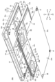
図8は、変形例に係る情報機器システム10Aの分解斜視図である。 Figure 8 is an exploded perspective view of an information device system 10A according to a modified example.

図8に示す情報機器システム10Aは、図2等に示す情報機器システム10と比べて、携帯用情報機器12及び拡張装置14と構成の異なる携帯用情報機器12A及び拡張装置14Aを備える。携帯用情報機器12Aは、携帯用情報機器12よりも構成を簡素化し、薄型化及び軽量化を向上させたものである。 Compared to the information device system 10 shown in FIG. 2 etc., the information device system 10A shown in FIG. 8 includes a portable information device 12A and an expansion device 14A that are different in configuration from the portable information device 12 and the expansion device 14. The portable information device 12A has a simpler configuration than the portable information device 12 and is thinner and lighter.

携帯用情報機器12Aは、例えばヒートパイプ38、ヒートシンク39及びファン40を搭載していない。代わりに携帯用情報機器12Aは、例えば筐体本体22にCPU34aの熱を拡散するための金属プレートやベーパーチャンバを搭載することができる。これにより携帯用情報機器12Aは筐体本体22の収容部品を一層削減でき、さらなる薄型化及び小型化が可能となる。携帯用情報機器12Aはファン40を搭載しないことで通気口42及び補助通気口43も省略することができる。これにより携帯用情報機器12Aの外観品質が向上する。 The portable information device 12A is not equipped with, for example, a heat pipe 38, a heat sink 39, or a fan 40. Instead, the portable information device 12A can be equipped with, for example, a metal plate or a vapor chamber in the housing body 22 to diffuse heat from the CPU 34a. This allows the portable information device 12A to further reduce the number of components housed in the housing body 22, making it possible to make the device even thinner and more compact. By not installing the fan 40, the portable information device 12A can also omit the vent 42 and auxiliary vent 43. This improves the appearance quality of the portable information device 12A.

携帯用情報機器12Aを構成するカバー部材24Aは、上記したカバー部材24と比べて底面通気口45,46を持たない構成とすることができる。携帯用情報機器12Aはファン40を備えない。そこで、カバー部材24Aは底面通気口45,46を備えないことで、携帯用情報機器12Aの底面をよりフラットに形成でき、外観品質を一層向上させることができる。 The cover member 24A constituting the portable information device 12A can be configured to not have bottom vents 45, 46, as compared to the cover member 24 described above. The portable information device 12A does not have a fan 40. Therefore, by not having bottom vents 45, 46 in the cover member 24A, the bottom surface of the portable information device 12A can be made flatter, further improving the appearance quality.

拡張装置14Aは、上記した拡張装置14と比べて、例えばX方向の各立壁50cに側面通気口78を有することができる。側面通気口78は左右の立壁50cに並列された複数の小窓で形成されている。側面通気口78は、ファン70の吸込口70bに対する外気の導入口となる。つまり拡張装置14Aのファン70は、側面通気口78から吸い込んだ外気を吐出口70aからヒートシンク69を通して通気口72へと排気することができる。拡張装置14Aのファン70は、さらに拡張筐体50の上面50aの開口部52を介して筐体本体22内の熱を吸引し、通気口72へと排気することもできる。 Compared to the above-mentioned expansion device 14, the expansion device 14A can have a side vent 78 on each vertical wall 50c in the X direction, for example. The side vent 78 is formed of multiple small windows arranged in parallel on the left and right vertical walls 50c. The side vent 78 serves as an inlet for outside air to the intake port 70b of the fan 70. In other words, the fan 70 of the expansion device 14A can exhaust the outside air sucked in from the side vent 78 through the exhaust port 70a and the heat sink 69 to the vent 72. The fan 70 of the expansion device 14A can also suck in heat from within the housing body 22 through the opening 52 on the top surface 50a of the expansion housing 50 and exhaust it to the vent 72.

このように情報機器システム10Aは、ファンレスの携帯用情報機器12Aを備えることで携帯用情報機器12の単独使用時の薄型化及び軽量化を図ることができる。しかも情報機器システム10Aは拡張装置14Aのファン70を用いて携帯用情報機器12Aの冷却も可能である。このため携帯用情報機器12Aは拡張装置14Aを連結することで、CPU34aのパフォーマンスを大幅に向上させることもできる。 In this way, by providing the fanless portable information device 12A, the information device system 10A can reduce the thickness and weight of the portable information device 12 when used alone. Furthermore, the information device system 10A can also cool the portable information device 12A using the fan 70 of the expansion device 14A. Therefore, by connecting the expansion device 14A to the portable information device 12A, the performance of the CPU 34a can be significantly improved.

図8に示すように、拡張装置14Aは上面50aに臨む受熱部材80を備えることができる。受熱部材80は銅やアルミニウム等の熱伝導率の高い金属プレートである。受熱部材80は例えば所定のヒートパイプやベーパーチャンバ等を介してヒートシンク69と熱的に接続されている。受熱部材80は拡張装置14Aが携帯用情報機器12Aに連結された際、CPU34aと熱的に接続される。これにより拡張装置14Aは受熱部材80を介してCPU34aを一層効率的に冷却することができる。 As shown in FIG. 8, the expansion device 14A can be provided with a heat receiving member 80 facing the upper surface 50a. The heat receiving member 80 is a metal plate with high thermal conductivity such as copper or aluminum. The heat receiving member 80 is thermally connected to the heat sink 69, for example, via a specified heat pipe or vapor chamber. When the expansion device 14A is connected to the portable information device 12A, the heat receiving member 80 is thermally connected to the CPU 34a. This allows the expansion device 14A to cool the CPU 34a more efficiently via the heat receiving member 80.

なお、本発明は、上記した実施形態に限定されるものではなく、本発明の主旨を逸脱しない範囲で自由に変更できることは勿論である。 The present invention is not limited to the above-described embodiment, and can of course be freely modified without departing from the spirit of the present invention.

拡張装置14,14Aは、拡張筐体50の底面50bに開口部53を持たず、カバー部材24,24Aと同様なプレート部材で底面50bを塞いだ構成とすることもできる。この場合、拡張装置14,14Aはカバー部材24を連結するためのカバー連結機構60は不要となる。 The expansion unit 14, 14A may be configured so that the bottom surface 50b of the expansion housing 50 does not have an opening 53, and the bottom surface 50b is covered with a plate member similar to the cover member 24, 24A. In this case, the expansion unit 14, 14A does not require a cover connection mechanism 60 for connecting the cover member 24.

10 情報機器システム
12,12A 携帯用情報機器
14,14A 拡張装置
22 筐体本体
24 カバー部材
31,47 脚部
32,60 カバー連結機構
44 孔部
48,58 連結機構
50 拡張筐体
54 穴部
56 拡張脚部
REFERENCE SIGNS LIST 10 Information device system 12, 12A Portable information device 14, 14A Expansion device 22 Housing body 24 Cover member 31, 47 Leg 32, 60 Cover connection mechanism 44 Hole 48, 58 Connection mechanism 50 Expansion housing 54 Hole 56 Expansion leg

Claims (4)

携帯用情報機器と、前記携帯用情報機器に着脱可能に連結される拡張装置と、を備える情報機器システムであって、
前記携帯用情報機器は、
底面が開口した筐体本体と、
前記筐体本体の底面側に設けられた第1カバー連結機構と、
前記第1カバー連結機構に着脱される第1連結機構を有し、前記筐体本体の底面を着脱可能に閉じるカバー部材と、
を有し、
前記拡張装置は、
少なくとも上面が開口した拡張筐体と、
前記拡張筐体の上面側に設けられ、前記カバー部材が取り外された前記筐体本体の前記第1カバー連結機構に着脱されることで、該拡張装置を前記携帯用情報機器に連結する第2連結機構と、
を有し、
前記拡張筐体は、底面が開口し、該底面側に前記第1連結機構を着脱可能な第2カバー連結機構を有し、
前記カバー部材は、前記第1連結機構が前記第2カバー連結機構に着脱されることで、前記携帯用情報機器に連結された前記拡張筐体の底面を着脱可能に閉じるものであり、
前記携帯用情報機器は、前記筐体本体の底面から突出する脚部を有し、
前記拡張装置は、前記拡張筐体の底面から突出する拡張脚部を有し、
前記カバー部材は、前記脚部及び前記拡張脚部をそれぞれ挿通可能な孔部を有する
ことを特徴とする情報機器システム。
An information device system comprising: a portable information device; and an extension device detachably connected to the portable information device,
The portable information device includes:
A housing body having an open bottom;
a first cover connecting mechanism provided on a bottom surface side of the housing body;
a cover member having a first connecting mechanism that is detachably attached to the first cover connecting mechanism and that detachably closes the bottom surface of the housing main body;
having
The expansion device is
an expansion housing having at least an open top;
a second coupling mechanism provided on an upper surface side of the expansion housing, the second coupling mechanism being attached to and detached from the first cover coupling mechanism of the housing main body from which the cover member has been removed, thereby coupling the expansion device to the portable information device;
having
the expansion housing has an open bottom surface and a second cover connecting mechanism on the bottom surface side to which the first connecting mechanism can be attached and detached;
the cover member detachably closes a bottom surface of the expansion housing connected to the portable information device by attaching and detaching the first connection mechanism to and from the second cover connection mechanism,
the portable information device has legs protruding from a bottom surface of the housing body,
The expansion device has an expansion leg protruding from a bottom surface of the expansion housing,
The cover member has holes through which the leg portion and the extension leg portion can be inserted.
An information device system comprising:
請求項に記載の情報機器システムであって、
前記拡張装置は、前記拡張筐体の上面に臨むように設けられ、前記脚部を位置決めして挿入可能な穴部を有する
ことを特徴とする情報機器システム。
2. The information device system according to claim 1 ,
The information equipment system is characterized in that the expansion device is provided facing an upper surface of the expansion housing and has holes into which the legs can be inserted for positioning the legs.
請求項又はに記載の情報機器システムであって、
前記カバー部材の前記孔部は、前記脚部及び前記拡張脚部をそれぞれ位置決めして挿通可能である
ことを特徴とする情報機器システム。
3. The information device system according to claim 1 ,
an information device system, characterized in that the hole of the cover member allows the leg portion and the extension leg portion to be inserted therethrough while being positioned therethrough,
携帯用情報機器と、前記携帯用情報機器に着脱可能に連結される拡張装置と、を備える情報機器システムであって、
前記携帯用情報機器は、
底面が開口した筐体本体と、
前記筐体本体の底面側に設けられた第1カバー連結機構と、
前記第1カバー連結機構に着脱される第1連結機構を有し、前記筐体本体の底面を着脱可能に閉じるカバー部材と、
を有し、
前記拡張装置は、
少なくとも上面が開口した拡張筐体と、
前記拡張筐体の上面側に設けられ、前記カバー部材が取り外された前記筐体本体の前記第1カバー連結機構に着脱されることで、該拡張装置を前記携帯用情報機器に連結する第2連結機構と、
を有し、
前記拡張筐体には、少なくとも冷却モジュールが搭載され、
前記冷却モジュールは、前記筐体本体から前記カバー部材が取り外され、前記拡張装置が前記携帯用情報機器に連結された状態において、前記筐体本体の底面の開口を通して該筐体本体の内部を冷却可能である
ことを特徴とする情報機器システム。
An information device system comprising: a portable information device; and an extension device detachably connected to the portable information device,
The portable information device includes:
A housing body having an open bottom;
a first cover connecting mechanism provided on a bottom surface side of the housing body;
a cover member having a first connecting mechanism that is detachably attached to the first cover connecting mechanism and that detachably closes the bottom surface of the housing main body;
having
The expansion device is
an expansion housing having at least an open top;
a second coupling mechanism provided on an upper surface side of the expansion housing, the second coupling mechanism being attached to and detached from the first cover coupling mechanism of the housing main body from which the cover member has been removed, thereby coupling the expansion device to the portable information device;
having
At least a cooling module is mounted on the expansion enclosure,
an information device system, characterized in that the cooling module is capable of cooling the inside of the housing body through an opening on the bottom surface of the housing body when the cover member is removed from the housing body and the expansion device is connected to the portable information device.
JP2024185889A 2024-10-22 2024-10-22 Information Equipment System Active JP7686866B1 (en)

Priority Applications (1)

Application Number Priority Date Filing Date Title
JP2024185889A JP7686866B1 (en) 2024-10-22 2024-10-22 Information Equipment System

Applications Claiming Priority (1)

Application Number Priority Date Filing Date Title
JP2024185889A JP7686866B1 (en) 2024-10-22 2024-10-22 Information Equipment System

Publications (1)

Publication Number Publication Date
JP7686866B1 true JP7686866B1 (en) 2025-06-02

Family

ID=95895084

Family Applications (1)

Application Number Title Priority Date Filing Date
JP2024185889A Active JP7686866B1 (en) 2024-10-22 2024-10-22 Information Equipment System

Country Status (1)

Country Link
JP (1) JP7686866B1 (en)

Citations (3)

* Cited by examiner, † Cited by third party
Publication number Priority date Publication date Assignee Title
JPH09222906A (en) * 1995-10-10 1997-08-26 Foxboro Co:The Field controller for control system
JP2019160103A (en) * 2018-03-16 2019-09-19 サクサ株式会社 Electronic device locking structure
JP2021190099A (en) * 2020-05-29 2021-12-13 技嘉科技股▲ふん▼有限公司Giga−Byte Technology Co., Ltd. Stacked computer system

Patent Citations (3)

* Cited by examiner, † Cited by third party
Publication number Priority date Publication date Assignee Title
JPH09222906A (en) * 1995-10-10 1997-08-26 Foxboro Co:The Field controller for control system
JP2019160103A (en) * 2018-03-16 2019-09-19 サクサ株式会社 Electronic device locking structure
JP2021190099A (en) * 2020-05-29 2021-12-13 技嘉科技股▲ふん▼有限公司Giga−Byte Technology Co., Ltd. Stacked computer system

Similar Documents

Publication Publication Date Title
US6842333B2 (en) Portable electronic device having LCD and touch screen
US6574102B2 (en) Docking station for portable computer and docking structure thereof
US8199524B2 (en) Electronic device and metal plate member
JPWO2015092942A1 (en) Electronics
US9148966B2 (en) Electronic device
CN100561401C (en) Electronics and Cooling Units
US20080080125A1 (en) Electronic device
JP7686866B1 (en) Information Equipment System
US20080080136A1 (en) Electronic device
US11609616B2 (en) Portable electronic apparatus having detachable key cap
JP5344247B2 (en) Electronics
JP5263406B2 (en) Electronics
US20080259556A1 (en) Modular graphics expansion system
JPWO2011061858A1 (en) Display device and electronic device
CN113258621B (en) Wireless charging equipment
US20080130214A1 (en) Mobile motherboard
JP5454583B2 (en) Electronics
JP5250702B2 (en) Electronics
CN218181400U (en) A New Type of Multifunctional Laptop Shell
CN217217288U (en) Novel power adapter suitable for notebook computer is last
JP7702033B1 (en) electronic equipment
WO2005074343A1 (en) Electronic device
CN221574258U (en) Connector terminal, data line and electronic equipment
JP7250086B1 (en) Electronics
JP7612905B1 (en) Electronics

Legal Events

Date Code Title Description
A621 Written request for application examination

Free format text: JAPANESE INTERMEDIATE CODE: A621

Effective date: 20241022

A711 Notification of change in applicant

Free format text: JAPANESE INTERMEDIATE CODE: A711

Effective date: 20241223

A131 Notification of reasons for refusal

Free format text: JAPANESE INTERMEDIATE CODE: A131

Effective date: 20250325

A521 Request for written amendment filed

Free format text: JAPANESE INTERMEDIATE CODE: A523

Effective date: 20250421

TRDD Decision of grant or rejection written
A01 Written decision to grant a patent or to grant a registration (utility model)

Free format text: JAPANESE INTERMEDIATE CODE: A01

Effective date: 20250507

A61 First payment of annual fees (during grant procedure)

Free format text: JAPANESE INTERMEDIATE CODE: A61

Effective date: 20250521

R150 Certificate of patent or registration of utility model

Ref document number: 7686866

Country of ref document: JP

Free format text: JAPANESE INTERMEDIATE CODE: R150