JP7686841B1 - Information providing device, information providing method, and program - Google Patents
Information providing device, information providing method, and program Download PDFInfo
- Publication number
- JP7686841B1 JP7686841B1 JP2024077991A JP2024077991A JP7686841B1 JP 7686841 B1 JP7686841 B1 JP 7686841B1 JP 2024077991 A JP2024077991 A JP 2024077991A JP 2024077991 A JP2024077991 A JP 2024077991A JP 7686841 B1 JP7686841 B1 JP 7686841B1
- Authority
- JP
- Japan
- Prior art keywords
- repair
- locations
- unit
- information
- contents
- Prior art date
- Legal status (The legal status is an assumption and is not a legal conclusion. Google has not performed a legal analysis and makes no representation as to the accuracy of the status listed.)
- Active
Links
Images


Abstract
【課題】建物の劣化及び損耗に関する正確な情報を提供すること。【解決手段】サーバ10は、計算部132と、提供部133と、を有する。計算部132は、建物を撮影した撮影画像を基に、撮影画像の特定の領域に含まれる建物の部分における修復箇所、修復内容及び修復費用を計算し、特定の領域内の複数の修復箇所に、修復内容に応じて優先度を付ける。提供部133は、特定の領域内の複数の修復箇所の修復内容及び修復費用を統合した情報を提供する。【選択図】図2[Problem] To provide accurate information regarding deterioration and wear of buildings. [Solution] A server 10 has a calculation unit 132 and a provision unit 133. The calculation unit 132 calculates the repair locations, repair contents, and repair costs for parts of the building included in a specific area of the photographed image based on a photographed image of the building, and prioritizes multiple repair locations within the specific area according to the repair contents. The provision unit 133 provides information that integrates the repair contents and repair costs for multiple repair locations within the specific area. [Selected Figure] Figure 2
Description
本発明は、情報提供装置、情報提供方法、及びプログラムに関する。 The present invention relates to an information providing device, an information providing method, and a program.
建物及び建物に備えられた設備は、時間の経過とともに劣化し、損耗する。例えば、不動産賃貸業においては、貸し出した物件(部屋等)の劣化及び損耗に伴う修復の要否を把握することが必要になる。 Buildings and the equipment installed in them deteriorate and wear out over time. For example, in the real estate rental business, it is necessary to understand whether repairs are required due to deterioration and wear of rented properties (rooms, etc.).
従来、建物を撮影した画像及び建物から発生した音を基に、建物の診断を行うシステムが知られている(例えば、特許文献1を参照)。また、建築現場及び不動産物件において、360°カメラで施工記録の写真を撮影する方法が知られている(例えば、非特許文献1を参照)。また、互いに異なる日時に撮影した建物の写真を比較することで、建物の劣化及び損耗の度合いを算出する技術が知られている(例えば、特許文献2を参照)。 Conventionally, a system is known that diagnoses a building based on images of the building and sounds generated by the building (see, for example, Patent Document 1). Also, a method is known for taking photos of construction records at construction sites and real estate properties using a 360° camera (see, for example, Non-Patent Document 1). Also, a technology is known that calculates the degree of deterioration and wear of a building by comparing photos of the building taken at different dates and times (see, for example, Patent Document 2).
しかしながら、従来の技術では、建物の劣化及び損耗に関する正確な情報が提供されない場合があるという問題がある。 However, conventional technology has the problem that it may not provide accurate information about the deterioration and wear of buildings.
例えば、建物の室内の1つの壁面に傷及び汚れがある場合、壁面の壁紙を交換することで、傷及び汚れの両方の修復が可能である。一方で、特許文献2に記載の技術では、傷及び汚れのそれぞれが別個の損耗とみなされ、傷を修復するための壁紙の交換、及び汚れを取るための清掃の両方の対応が必要であると判断される場合がある。このような場合、修復のために余分なコストが発生することになる。 For example, if there is a scratch and stain on one of the walls inside a building, it is possible to repair both the scratch and the stain by replacing the wallpaper on the wall. On the other hand, with the technology described in Patent Document 2, the scratch and the stain are each considered to be separate damages, and it may be determined that both replacing the wallpaper to repair the scratch and cleaning to remove the stain are necessary. In such cases, extra costs will be incurred for the repair.
本発明は、上記に鑑みてなされたものであって、建物の劣化及び損耗に関する正確な情報を提供することを目的とする。 The present invention was made in consideration of the above, and aims to provide accurate information regarding deterioration and wear of buildings.
上述した課題を解決し、目的を達成するために、本発明の情報提供装置は、建物を撮影した撮影画像を基に、前記撮影画像の特定の領域に含まれる前記建物の部分における修復箇所、修復内容及び修復費用を計算し、前記特定の領域内の複数の修復箇所に、前記修復内容に応じて優先度を付ける計算部と、前記特定の領域内の複数の修復箇所の前記修復内容及び前記修復費用を統合した情報を提供する提供部と、を有することを特徴とする。 In order to solve the above-mentioned problems and achieve the object, the information providing device of the present invention is characterized by having a calculation unit that calculates the repair locations, repair contents, and repair costs for parts of the building included in a specific area of a photographed image of the building based on the photographed image, and prioritizes multiple repair locations within the specific area according to the repair contents, and a providing unit that provides information that integrates the repair contents and the repair costs for multiple repair locations within the specific area.
本発明によれば、建物の劣化及び損耗に関する正確な情報を提供することができる。 The present invention can provide accurate information regarding deterioration and wear of buildings.
以下に、本願に係る情報提供装置、情報提供方法、及びプログラムを図面に基づいて詳細に説明する。なお、本発明は、以下に説明する実施形態により限定されるものではない。 The information providing device, information providing method, and program according to the present application are described in detail below with reference to the drawings. Note that the present invention is not limited to the embodiments described below.
[第1の実施形態]
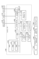
図1を用いて、情報提供システム1の構成を説明する。図1は、情報提供システムの構成例を示す図である。
[First embodiment]
The configuration of an
一例として、情報提供システム1は、住居として貸し出される建物(賃貸物件)の損耗に関する情報を提供する。情報提供システム1によって提供される情報は、不動産管理会社、不動産情報提供業者、工務店担当者、仲介業者、貸主、借主等によって利用される。
As an example, the
特に、情報提供システム1は、建物及び設備の修復に関する情報を提供する。建物及び設備は、経年劣化、通常損耗、及び特別損耗が生じることによって、修復が必要になる場合がある。経年劣化は、自然な劣化及び損耗等である。通常損耗は、借主の通常の使用により生ずる損耗等である。特別損耗は、借主の故意・過失、善管注意義務違反、その他通常の使用を超えるような使用による損耗等である。
In particular, the
例えば、情報提供システム1は、修復が必要な箇所(修復箇所)、修復の内容、及び修復にかかる費用を情報として提供する。
For example, the
本実施形態の情報提供システム1は、特許文献2に記載の情報処理装置を含むシステムと同様の構成を有していてもよい。特に、情報提供システム1は、特許文献2に記載の情報処理装置を含むシステムと同様の方法で画像の取得、及び画面の提供を行うことができる。例えば、情報提供システム1は、特許文献2に記載の情報処理装置を含むシステムに機能を追加することによって実現される。
The
図1に示すように、情報提供システム1は、サーバ10、及び端末20を有する。サーバ10は、端末20とネットワークNを介して接続される。ネットワークNは、例えばインターネットである。サーバ10は、情報提供装置の一例である。
As shown in FIG. 1, the
ユーザは、端末20に備えられたカメラを用いて、建物50を撮影する。本実施形態では、端末20によって建物の室内が撮影される場合を例に挙げて説明する。ただし、端末20によって撮影される対象は室内に限られず、建物の外観等であってもよい。
The user photographs the
サーバ10は、端末20から画像を取得する。サーバ10は、取得した画像に基づき、建物の修復が必要な箇所、修復内容、及び修復費用を計算する。サーバ10による計算結果は、端末20又は他の装置に提供される。
The
図2を用いて、サーバ10の構成を説明する。図2は、サーバの構成例を示す図である。図2に示すように、サーバ10は、通信部11、記憶部12、及び制御部13を有する。
The configuration of the
通信部11は、端末20を含む他の装置と通信を行うためのインタフェースである。例えば、通信部11はNIC(Network Interface Card)である。
The communication unit 11 is an interface for communicating with other devices including the
記憶部12は、HDD(Hard Disk Drive)、SSD(Solid State Drive)、光ディスク等の記憶装置である。なお、記憶部12は、RAM(Random Access Memory)、フラッシュメモリ、NVSRAM(Non Volatile Static Random Access Memory)等のデータを書き換え可能な半導体メモリであってもよい。記憶部12は、サーバ10で実行されるOS(Operating System)や各種プログラムを記憶する。記憶部12は、モデル情報121及び物件テーブル122を記憶する。
The storage unit 12 is a storage device such as a hard disk drive (HDD), a solid state drive (SSD), or an optical disk. The storage unit 12 may be a semiconductor memory in which data can be rewritten, such as a random access memory (RAM), a flash memory, or a non-volatile static random access memory (NVSRAM). The storage unit 12 stores the operating system (OS) and various programs executed by the
モデル情報121は、機械学習モデルを構築するためのパラメータ等の情報である。例えば、モデル情報121は、ニューラルネットワークの重み及びバイアス等である。また、モデル情報121は、互いに用途が異なる複数の機械学習モデルの情報を含んでいてもよい。 Model information 121 is information such as parameters for constructing a machine learning model. For example, model information 121 is weights and biases of a neural network. Model information 121 may also include information on multiple machine learning models with different uses.
物件テーブル122は、物件に関するデータが格納されるテーブルである。本実施形態では、物件テーブル122の各レコードは、集合住宅(アパート、マンション等)を構成する部屋のそれぞれに対応する。また、以降の説明では、各部屋を物件と呼ぶ場合がある。 The property table 122 is a table in which data related to properties is stored. In this embodiment, each record in the property table 122 corresponds to each room that makes up an apartment building (apartment, condominium, etc.). In the following description, each room may be referred to as a property.
図3は、物件テーブルの例を示す図である。図3に示すように、物件テーブル122は、「物件名」、「住所」、「部屋番号」、「間取り」、及び「画像」といったカラムを有する。 Figure 3 is a diagram showing an example of a property table. As shown in Figure 3, the property table 122 has columns such as "Property Name", "Address", "Room Number", "Layout", and "Image".
カラム「物件名」には、物件の名称が格納される。カラム「住所」には、物件の住所が格納される。カラム「部屋番号」には、物件の部屋番号が格納される。カラム「間取り」には、物件の間取りが格納される。カラム「画像」には、物件の画像の情報(例えば、画像ファイルのパス、又はバイナリデータ)が格納される。 The column "Property Name" stores the name of the property. The column "Address" stores the address of the property. The column "Room Number" stores the room number of the property. The column "Layout" stores the layout of the property. The column "Image" stores information about the image of the property (e.g., the path to the image file or binary data).
例えば、図3の物件テーブル122の1行目のレコードには、「A県B市1-2-3」である「Xアパート」の「101号室」の間取りが「1LDK」であることが示されている。また、物件テーブル122の1行目のレコードには、「101号室」の画像に関する情報が格納されている。 For example, the record in the first row of the property table 122 in FIG. 3 indicates that the layout of "Room 101" in "X Apartment" located at "1-2-3, B City, A Prefecture" is "1LDK." The record in the first row of the property table 122 also stores information about an image of "Room 101."
図2に戻り、制御部13は、サーバ10の全体を制御する。制御部13は、例えば、CPU(Central Processing Unit)、MPU(Micro Processing Unit)、GPU(Graphics Processing Unit)等の電子回路や、ASIC(Application Specific Integrated Circuit)、FPGA(Field Programmable Gate Array)等の集積回路である。
Returning to FIG. 2, the
制御部13は、各種の処理手順を規定したプログラムや制御データを格納するための内部メモリを有し、内部メモリを用いて各処理を実行する。また、制御部13は、各種のプログラムが動作することにより各種の処理部として機能する。例えば、制御部13は、特定部131、計算部132、及び提供部133を有する。
The
特定部131は、画像が撮影された位置を特定する。例えば、特定部131は、画像とともに取得した方位等を基に、画像の撮影位置を特定する。 The identification unit 131 identifies the location where the image was taken. For example, the identification unit 131 identifies the location where the image was taken based on the direction, etc., acquired together with the image.
特定部131は、機械学習モデルを使って撮影位置を特定することができる。また、特定部131は、物件テーブル122に格納された画像をテンプレートとしたテンプレートマッチングによって撮影位置を特定してもよい。 The identification unit 131 can identify the shooting location using a machine learning model. The identification unit 131 may also identify the shooting location by template matching using an image stored in the property table 122 as a template.
計算部132は、画像を基に、修復の必要がある位置、修復内容及び修復費用を計算する。計算部132は、画像を入力とし、修復の必要がある位置、修復内容及び修復費用を出力する機械学習モデルを使って計算を行う。計算部132は、特定部131によって特定された撮影位置を参照して計算を行ってもよい。 The calculation unit 132 calculates the location that needs to be repaired, the repair content, and the repair cost based on the image. The calculation unit 132 performs calculations using a machine learning model that takes the image as input and outputs the location that needs to be repaired, the repair content, and the repair cost. The calculation unit 132 may perform calculations by referring to the shooting location identified by the identification unit 131.
提供部133は、計算部132による計算結果を、端末20又は他の装置に提供する。例えば、提供部133は、計算結果を表示する画面を端末20に表示させる。
The providing
図4を用いて、端末20の構成を説明する。図4は、端末の構成例を示す図である。図4に示すように、端末20は、通信部21、センサ部22、表示部23、記憶部24、及び制御部25を有する。端末20は、スマートフォン、タブレット型コンピュータ、パーソナルコンピュータ等である。 The configuration of the terminal 20 will be described using FIG. 4. FIG. 4 is a diagram showing an example of the configuration of a terminal. As shown in FIG. 4, the terminal 20 has a communication unit 21, a sensor unit 22, a display unit 23, a memory unit 24, and a control unit 25. The terminal 20 is a smartphone, a tablet computer, a personal computer, etc.
通信部21は、端末20を含む他の装置と通信を行うためのインタフェースである。例えば、通信部21はNICである。 The communication unit 21 is an interface for communicating with other devices including the terminal 20. For example, the communication unit 21 is a NIC.
センサ部22は、複数のセンサである。カメラ221は、画像を撮影する。深度センサ222は、赤外線等により対象物との距離を測定する。例えば、深度センサ222は、カメラ221の撮影方向と同じ方向にある対象物との距離を測定する。方位センサ223は、地磁気を検知し、端末20の向きを測定する。例えば、方位センサ223は、カメラ221の撮影方向を3軸(例えば、東西の軸、南北の軸、上下の軸)の方位として出力する。 The sensor unit 22 is a plurality of sensors. The camera 221 captures an image. The depth sensor 222 measures the distance to an object using infrared rays or the like. For example, the depth sensor 222 measures the distance to an object in the same direction as the shooting direction of the camera 221. The orientation sensor 223 detects geomagnetism and measures the orientation of the terminal 20. For example, the orientation sensor 223 outputs the shooting direction of the camera 221 as the orientation of three axes (e.g., east-west axis, north-south axis, and up-down axis).
また、制御部25は、センサ部22による測定結果を基に、3D画像、パノラマ画像、及び全天球画像といった画像を生成してもよい。 The control unit 25 may also generate images such as 3D images, panoramic images, and spherical images based on the measurement results from the sensor unit 22.
表示部23は、画像を表示するディスプレイである。表示部23は、タッチパネルディスプレイであってもよい。 The display unit 23 is a display that displays images. The display unit 23 may be a touch panel display.
記憶部24は、HDD、SSD、光ディスク等の記憶装置である。なお、記憶部24は、RAM、フラッシュメモリ、NVSRAM等のデータを書き換え可能な半導体メモリであってもよい。記憶部24は、端末20で実行されるOSや各種プログラムを記憶する。 The storage unit 24 is a storage device such as an HDD, SSD, or optical disk. The storage unit 24 may also be a semiconductor memory in which data can be rewritten, such as a RAM, flash memory, or NVSRAM. The storage unit 24 stores the OS and various programs executed by the terminal 20.
制御部25は、端末20の全体を制御する。制御部25は、例えば、CPU、MPU、GPU等の電子回路や、ASIC、FPGA等の集積回路である。
The control unit 25 controls the
制御部25は、各種の処理手順を規定したプログラムや制御データを格納するための内部メモリを有し、内部メモリを用いて各処理を実行する。また、制御部25は、各種のプログラムが動作することにより各種の処理部として機能する。例えば、制御部25は、取得部251、提供部252、及び表示制御部253を有する。 The control unit 25 has an internal memory for storing programs and control data that define various processing procedures, and executes each process using the internal memory. The control unit 25 also functions as various processing units by the operation of various programs. For example, the control unit 25 has an acquisition unit 251, a provision unit 252, and a display control unit 253.
取得部251は、センサ部22から測定結果を取得する。取得部251は、カメラ221によって撮影された画像(撮影画像)、深度センサ222によって測定された深度、及び方位センサ223によって測定された方位を取得する。 The acquisition unit 251 acquires the measurement results from the sensor unit 22. The acquisition unit 251 acquires the image captured by the camera 221 (captured image), the depth measured by the depth sensor 222, and the direction measured by the direction sensor 223.
提供部252は、取得部251によって取得された情報をサーバ10に提供する。例えば、提供部252は、画像、深度、及び方位を提供する。
The providing unit 252 provides the information acquired by the acquiring unit 251 to the
表示制御部253は、表示部23に画面を表示させる。表示制御部253は、サーバ10から受信したデータに基づいて画面を表示させる。
The display control unit 253 causes the display unit 23 to display a screen. The display control unit 253 causes the screen to be displayed based on the data received from the
図5を用いて、サーバ10が情報を提供する処理の詳細を説明する。図5は、提供される情報を説明する図である。図5の画面70は、サーバ10から提供される情報に基づき、端末20に表示される。
The process by which the
図5に示すように、画面70は、領域71、領域72、領域73、領域74、及び領域75を含む。例えば、画面70は、提供部133によって生成されたものであってもよい。提供部133は、画像、オブジェクト及びテキストを画面に配置する。
As shown in FIG. 5,
領域71には、物件(ここでは、部屋を含む集合住宅)の名称、及び住所が表示される。領域72には、部屋番号が選択可能に表示される。領域73には、部屋の間取り図731、方位オブジェクト732、及び3軸オブジェクト733が表示される。例えば、領域71、領域72及び領域73に表示される情報は、端末20からの指定に応じて、提供部133が、記憶部12に記憶された物件テーブル122等を参照して提供する。
方位オブジェクト732は、間取り図731に対応し、方位を表すオブジェクトである。方位オブジェクト732の上側が北を指している。すなわち、間取り図731の下から上に向かう方位が北であり、間取り図731の上から下に向かう方位が南である。
The
3軸オブジェクト733は、部屋の位置を表すための3軸の方向を示すオブジェクトである。ここでは、x軸は東から西に向かう軸であり、y軸は南から北に向かう軸であり、z軸は鉛直上向きの軸である。
The three-
また、間取り図731の中には、撮影位置オブジェクト734が表示される。撮影位置オブジェクト734は、特定部131によって特定された、画像の撮影位置及び方向を示している。例えば、撮影位置オブジェクト734は、部屋の中央付近から南向きに画像が撮影されたことを示している。
A
領域74には、端末20によって撮影画像に情報が付加された画像が表示される。領域74には、3軸オブジェクト741が表示される。3軸オブジェクト741は、間取り図731の3軸オブジェクト733と対応している。例えば、3軸オブジェクト741において、x軸は東から西に向かう軸であり、y軸は南から北に向かう軸であり、z軸は鉛直上向きの軸である。
In
ラベル742、ラベル743、及びラベル744は、計算部132によって計算された修復が必要な箇所に付される。また、ラベル742、ラベル743、及びラベル744には、修復が必要な箇所に応じた、修復内容、及び修復費用がテキスト等により表示される。
例えば、ラベル742は、修復が必要な箇所である窓ガラスに付されている。そして、ラベル742には、修復内容が「リビング南側窓ガラス:汚れありのため要清掃」であり、修復費用が「¥4,000」であることが示されている。
For example,
また、領域75には、修復内容及び修復費用が一覧表示される。領域75の各項目は、各ラベルに対応している。
ここで、計算部132による計算処理について説明する。計算部132は、モデル情報121を基に構築した訓練済みの機械学習モデルに、必要なデータを入力し、出力を得る。また、計算部132は、機械学習モデルの出力を基に、さらに計算を行ってもよい。 Here, the calculation process by the calculation unit 132 will be described. The calculation unit 132 inputs necessary data into a trained machine learning model constructed based on the model information 121, and obtains an output. The calculation unit 132 may also perform further calculations based on the output of the machine learning model.
計算部132は、修復情報計算モデルに、画像を入力する。修復情報計算モデルは、画像を基に、画像に写る修復箇所、修復内容及び修復費用を出力するモデルである。修復情報計算モデルは、畳み込みニューラルネットワーク等の画像認識に用いられるモデルをベースにしたものであってもよい。 The calculation unit 132 inputs an image into the repair information calculation model. The repair information calculation model is a model that outputs the repair location, repair content, and repair cost shown in the image based on the image. The repair information calculation model may be based on a model used for image recognition such as a convolutional neural network.
例えば、修復情報計算モデルの訓練は、画像と、画像上の修復箇所、修復内容及び修復費用と、を組み合わせたデータによって行われる。例えば、修復情報計算モデルは、画像に写る部屋の壁、床、天井、開口部、及び建具等における、変色、傷、汚れ等を、矩形領域として検出する。修復情報計算モデルは、さらに、矩形領域ごとに、修復方法及び修復費用を計算する。 For example, the repair information calculation model is trained using data that combines an image with the location of repairs on the image, the repair content, and the repair cost. For example, the repair information calculation model detects discoloration, scratches, dirt, etc., as rectangular areas on the walls, floors, ceilings, openings, fittings, etc. of a room shown in an image. The repair information calculation model then calculates the repair method and repair cost for each rectangular area.
なお、サーバ10は、撮影画像と同様の位置から同様の向きで撮影した画像があれば、画像を比較することにより、修復箇所、修復内容、及び修復費用の計算精度を向上させることができる。サーバ10は、特許文献2に記載された方法と同様の方法により、第1の日時(例えば、借主の入居前)に撮影された画像と、第2の日時(例えば、借主の退去時)に撮影された画像と、を対比して求めた変化率を基に、修復箇所、修復内容、及び修復費用を計算してもよい。
If there is an image taken from the same position and in the same orientation as the captured image, the
提供部133は、画像上の修復箇所に対応する位置にラベルを配置するための情報を提供する。これにより、提供部133は、端末20等にラベルが付された画像を表示させることができる。例えば、提供部133は、画像上の修復箇所に対応する位置とともに、ラベルに表示される修復内容及び修復費用のテキストを提供する。
The providing
なお、提供部133は、修復箇所に対応する位置を、3軸オブジェクト733及び3軸オブジェクト741に示される座標空間の座標として提供することができる。また、ラベルは、テキストを表示するためのオブジェクトである。ラベルの形状は、図5に示すような吹き出し形式のものに限られず、テキストのみを表示するオブジェクトであってもよい。
The providing
これにより、図5に示すように、ラベルを修復箇所の近くに表示することが可能になる。その結果、ユーザは、修復箇所と修復内容及び修復費用を直感的に把握しやすくなる。 This makes it possible to display a label near the repair location, as shown in Figure 5. As a result, users can intuitively understand the repair location, repair details, and repair costs.
端末20の表示制御部253は、提供部133から提供された情報に基づき、検出された矩形領域を指し示すラベルを、撮影画像に配置する。そして、表示制御部253は、提供部133から提供された情報に基づき、ラベルに、修復内容及び修復費用を記載する。
The display control unit 253 of the terminal 20 places a label indicating the detected rectangular area on the captured image based on the information provided by the providing
提供部133は、画像上の修復箇所に対応する位置とともに、ラベルにテキストを入力可能であることを示す情報を提供する。この場合、表示制御部253は、提供部133から提供された情報に基づき、ラベルに修復内容及び修復費用を記載せずに、テキストを入力可能な状態にしておく。例えば、提供部133は、撮影画像に壁又は床のみが写っており、検出精度が低くなる場合に、テキストを入力可能なラベルを配置させる。
The providing
[複数の修復箇所が近くにある場合の処理]
例えば、建物の室内の1つの壁面に傷及び汚れがある場合、壁面の壁紙を交換することで、傷及び汚れの両方の修復が可能である。一方で、傷及び汚れのそれぞれを別個の損耗とみなし、傷を修復するための壁紙の交換、及び汚れを取るための清掃の両方の対応が必要であると判断される場合がある。このような場合、修復のために余分なコストが発生することになる。
[How to handle multiple repair points nearby]
For example, if there are scratches and stains on one wall in a building, it is possible to repair both the scratches and the stains by replacing the wallpaper on the wall. On the other hand, there are cases where the scratches and the stains are regarded as separate wear and tear, and it is determined that both replacing the wallpaper to repair the scratches and cleaning to remove the stains are necessary. In such cases, extra costs will be incurred for the repairs.
そこで、サーバ10は、余分なコストが発生しないように計算を行う。図6を用いて、複数の修復箇所が近くにある場合の処理を説明する。図6は、複数の修復箇所に対する処理を説明する図である。
Therefore, the
まず、計算部132は、画像の全部又は一部を、複数の領域に分割する。図6の例では、計算部132は、画像80に写る開口部(窓)を含む壁面を、領域811、領域812、領域813に分割する。
First, the calculation unit 132 divides all or part of the image into multiple regions. In the example of FIG. 6, the calculation unit 132 divides the wall surface including the opening (window) shown in the
計算部132は、画像分割用の機械学習モデルを用いて分割を行ってもよい。例えば、画像分割用の機械学習モデルの訓練は、画像と手動による画像の分割結果とを用いて行われる。 The calculation unit 132 may perform the segmentation using a machine learning model for image segmentation. For example, the machine learning model for image segmentation is trained using the images and the results of manual image segmentation.
また、計算部132は、1m四方の壁、窓とサッシといったような、あらかじめ定められた部分に領域を分割してもよい。 The calculation unit 132 may also divide the area into predefined parts, such as a 1m square wall, windows and sashes.
なお、画像80は、図5の画面70の撮影画像と同じである。このため、領域811、領域812、領域813は、南側の開口部を含む壁面に含まれる領域である。
Note that
計算部132は、建物を撮影した撮影画像を基に、撮影画像の特定の領域に含まれる建物の部分における修復箇所、修復内容及び修復費用を計算し、特定の領域内の複数の修復箇所に、修復内容に応じて優先度を付ける。 The calculation unit 132 calculates the repair locations, repair contents, and repair costs for parts of the building included in a specific area of the captured image based on the captured image of the building, and prioritizes the multiple repair locations within the specific area according to the repair contents.
計算部132は、修復内容の対象が、領域の広い部分に及ぶほど優先度を大きくする。例えば、修復内容が領域内の壁全体の壁紙を取り換えるものである場合、修復内容が領域内の壁の一部の拭き取り清掃を行うものである場合と比べて、計算部132は、優先度を大きくする。 The calculation unit 132 increases the priority as the repair content covers a larger portion of the area. For example, if the repair content involves replacing the wallpaper on an entire wall in the area, the calculation unit 132 increases the priority compared to when the repair content involves wiping and cleaning only a portion of the wall in the area.
計算部132は、領域において複数の修復内容が検出された場合、複数の修復内容のうち優先度が最大の修復内容を当該領域の修復内容に決定する。すなわち、提供部133は、特定の領域内の複数の修復箇所のうち、優先度が最も大きい修復箇所について、修復内容及び修復費用を提供する。
When multiple repair contents are detected in an area, the calculation unit 132 determines the repair content with the highest priority among the multiple repair contents as the repair content for the area. In other words, the
図6の例では、計算部132は、領域813において、矩形領域8102、及び矩形領域8103を修復箇所として検出する。このとき、計算部132は、矩形領域8102の修復内容を、壁紙の交換であることを計算によって特定する。また、計算部132は、矩形領域8103の修復内容を、拭き取り清掃であることを計算によって特定する。
In the example of FIG. 6, the calculation unit 132 detects
計算部132は、矩形領域8102の優先度を10とする。また、計算部132は、矩形領域8103の優先度を2とする。そして、計算部132は、最終的な修復内容に、矩形領域8102を含め、矩形領域8103を含めない。
The calculation unit 132 sets the priority of
図5の修復内容「リビング南側クロス貼り換え」は、矩形領域8102の修復内容である。一方で、図5には、矩形領域8103の修復内容である「リビング南側クロス拭き取り清掃」が掲載されていない。
The repair content in Figure 5, "Replacing wallpaper on the south side of the living room," is the repair content for
このように、計算部132は、複数の修復箇所のうち、修復内容が部材の交換である修復箇所に対し、修復内容が部材の清掃である修復箇所よりも大きい優先度を付ける。これにより、サーバ10は、壁紙の交換と清掃の両方の費用が生じることを防止することができる。
In this way, the calculation unit 132 assigns a higher priority to repair locations where the repair content is the replacement of parts among multiple repair locations than to repair locations where the repair content is the cleaning of parts. This allows the
なお、領域811の修復箇所は矩形領域8101の1か所のみであるため、計算部132は、領域811においては優先度を付ける処理を行わない。
Note that since the only repair location in
図7は、端末の処理の流れを示すフローチャートである。まず、図7に示すように、端末20は、カメラ221によって撮影された室内の画像を取得する(ステップS101)。また、端末20は、方位センサ223から端末20の方位を取得する(ステップS102)。 Figure 7 is a flowchart showing the flow of processing by the terminal. First, as shown in Figure 7, the terminal 20 acquires an image of the room captured by the camera 221 (step S101). The terminal 20 also acquires the direction of the terminal 20 from the direction sensor 223 (step S102).
次に、端末20は、取得した画像及び方位をサーバ10に送信する(ステップS103)。 Next, the terminal 20 transmits the acquired image and orientation to the server 10 (step S103).
その後、端末20は、修復が必要な位置、修復内容、及び費用をサーバ10から受信する(ステップS104)。端末20は、サーバ10から受信した情報を基に、画像を画面に表示し(ステップS105)、修復内容及び費用を、画像上の対応する位置に表示する(ステップS106)。
Then, the terminal 20 receives the location where repair is required, the repair content, and the cost from the server 10 (step S104). Based on the information received from the
図8は、サーバの処理の流れを示すフローチャートである。まず、図8に示すように、サーバ10は、端末20から画像及び方位を受信する(ステップS201)。
Figure 8 is a flowchart showing the flow of processing by the server. First, as shown in Figure 8, the
次に、サーバ10は、画像及び方位を基に、撮影位置を特定する(ステップS202)。そして、サーバ10は、画像を基に、修復が必要な位置、修復内容、及び費用を計算する(ステップS203)。サーバ10は、機械学習モデルを使って計算を行うことができる。
Next, the
続いて、サーバ10は、画像に写った室内の面を複数の領域に分割する(ステップS204)。サーバ10は、各領域の修復内容に優先度を付与する(ステップS205)。サーバ10は、優先度に応じて修復内容を統合する(ステップS206)。すなわち、サーバ10は、領域内の複数の修復内容のうち、優先度が最大の修復内容を残し、その他の修復内容を除外する。
Then, the
サーバ10は、計算結果を端末20に送信する(ステップS207)。サーバ10は、計算結果をそのまま送信してもよいし、計算結果を基に作成した画面のデータを送信してもよい。
The
[システム構成等]
図示した各装置の各構成要素は機能概念的なものであり、必ずしも物理的に図示のように構成されていることを要しない。すなわち、各装置の分散及び統合の具体的形態は図示のものに限られず、その全部又は一部を、各種の負荷や使用状況等に応じて、任意の単位で機能的又は物理的に分散又は統合して構成することができる。さらに、各装置にて行われる各処理機能は、その全部又は任意の一部が、CPU及び当該CPUにて解析実行されるプログラムにて実現され、あるいは、ワイヤードロジックによるハードウェアとして実現され得る。なお、プログラムは、CPUだけでなく、GPU等の他のプロセッサによって実行されてもよい。
[System configuration, etc.]
Each component of each device shown in the figure is a functional concept, and does not necessarily have to be physically configured as shown in the figure. In other words, the specific form of distribution and integration of each device is not limited to that shown in the figure, and all or a part of it can be functionally or physically distributed or integrated in any unit depending on various loads, usage conditions, etc. Furthermore, each processing function performed by each device can be realized in whole or in any part by a CPU and a program analyzed and executed by the CPU, or can be realized as hardware by wired logic. Note that the program may be executed not only by the CPU but also by other processors such as a GPU.
また、実施形態において説明した各処理のうち、自動的に行われるものとして説明した処理の全部又は一部を手動的に行うこともでき、あるいは、手動的に行われるものとして説明した処理の全部又は一部を公知の方法で自動的に行うこともできる。この他、上記文書中や図面中で示した処理手順、制御手順、具体的名称、各種のデータやパラメータを含む情報については、特記する場合を除いて任意に変更することができる。 Furthermore, among the processes described in the embodiments, all or part of the processes described as being performed automatically can be performed manually, or all or part of the processes described as being performed manually can be performed automatically using known methods. In addition, the information including the processing procedures, control procedures, specific names, various data, and parameters shown in the above documents and drawings can be changed as desired unless otherwise specified.
[プログラム]
一実施形態として、サーバ10は、パッケージソフトウェアやオンラインソフトウェアとして上記の処理を実行するプログラムを所望のコンピュータにインストールさせることによって実装できる。例えば、上記のプログラムを情報処理装置に実行させることにより、情報処理装置をサーバ10として機能させることができる。ここで言う情報処理装置には、デスクトップ型又はノート型のパーソナルコンピュータが含まれる。また、その他にも、情報処理装置には、タブレット型端末、スマートフォン、携帯電話機やPHS(Personal Handyphone System)等の移動体通信端末、さらには、PDA(Personal Digital Assistant)等のスレート端末等がその範疇に含まれる。
[program]
In one embodiment, the
また、サーバ10は、Webサーバとして実装することとしてもよいし、アウトソーシングによって上記の処理に関するサービスを提供するクラウドとして実装することとしてもかまわない。
Furthermore, the
図9は、プログラムを実行するコンピュータの構成例を示す図である。コンピュータ1000は、例えば、メモリ1010、CPU1020を有する。また、コンピュータ1000は、ハードディスクドライブインタフェース1030、ディスクドライブインタフェース1040、シリアルポートインタフェース1050、ビデオアダプタ1060、ネットワークインタフェース1070を有する。これらの各部は、バス1080によって接続される。
Figure 9 is a diagram showing an example of the configuration of a computer that executes a program. The
メモリ1010は、ROM(Read Only Memory)1011及びRAM(Random Access Memory)1012を含む。ROM1011は、例えば、BIOS(Basic Input Output System)等のブートプログラムを記憶する。ハードディスクドライブインタフェース1030は、ハードディスクドライブ1090に接続される。ディスクドライブインタフェース1040は、ディスクドライブ1100に接続される。例えば磁気ディスクや光ディスク等の着脱可能な記憶媒体が、ディスクドライブ1100に挿入される。シリアルポートインタフェース1050は、例えばマウス1110、キーボード1120に接続される。ビデオアダプタ1060は、例えばディスプレイ1130に接続される。
The memory 1010 includes a read only memory (ROM) 1011 and a random access memory (RAM) 1012. The ROM 1011 stores a boot program such as a basic input output system (BIOS). The hard
ハードディスクドライブ1090は、例えば、OS1091、アプリケーションプログラム1092、プログラムモジュール1093、プログラムデータ1094を記憶する。すなわち、サーバ10の各処理を規定するプログラムは、コンピュータにより実行可能なコードが記述されたプログラムモジュール1093として実装される。プログラムモジュール1093は、例えばハードディスクドライブ1090に記憶される。例えば、サーバ10における機能構成と同様の処理を実行するためのプログラムモジュール1093が、ハードディスクドライブ1090に記憶される。なお、ハードディスクドライブ1090は、SSD(Solid State Drive)により代替されてもよい。
The
また、上述した実施形態の処理で用いられる設定データは、プログラムデータ1094として、例えばメモリ1010やハードディスクドライブ1090に記憶される。そして、CPU1020は、メモリ1010やハードディスクドライブ1090に記憶されたプログラムモジュール1093やプログラムデータ1094を必要に応じてRAM1012に読み出して、上述した実施形態の処理を実行する。
The setting data used in the processing of the above-described embodiment is stored as
なお、プログラムモジュール1093やプログラムデータ1094は、ハードディスクドライブ1090に記憶される場合に限らず、例えば着脱可能な記憶媒体に記憶され、ディスクドライブ1100等を介してCPU1020によって読み出されてもよい。あるいは、プログラムモジュール1093及びプログラムデータ1094は、ネットワーク(LAN(Local Area Network)、WAN(Wide Area Network)等)を介して接続された他のコンピュータに記憶されてもよい。そして、プログラムモジュール1093及びプログラムデータ1094は、他のコンピュータから、ネットワークインタフェース1070を介してCPU1020によって読み出されてもよい。
The
N ネットワーク
10 サーバ
11、21 通信部
12、24 記憶部
13、25 制御部
20 端末
22 センサ部
23 表示部
70 画面
80 画像
71、72、73、74、75、811、812、813 領域
122 物件テーブル
221 カメラ
222 深度センサ
223 方位センサ
251 取得部
252 提供部
253 表示制御部
732 方位オブジェクト
733 3軸オブジェクト
734 撮影位置オブジェクト
741 3軸オブジェクト
742、743、744 ラベル
8101、8102、8103 矩形領域
Claims (5)
前記特定の領域内の複数の修復箇所の前記修復内容及び前記修復費用を統合した情報を提供する提供部と、
を有することを特徴とする情報提供装置。 a calculation unit that calculates, based on a photographed image of a building, repair locations, repair contents, and repair costs for a portion of the building included in a specific area of the photographed image, and prioritizes a plurality of repair locations within the specific area according to the repair contents;
a providing unit that provides integrated information of the repair contents and the repair costs of a plurality of repair locations within the specific area;
An information providing device comprising:
ことを特徴とする請求項1に記載の情報提供装置。 The information providing device according to claim 1 , wherein the providing unit provides the repair details and the repair cost for a repair location having the highest priority among a plurality of repair locations in the specific area.
ことを特徴とする請求項1又は2に記載の情報提供装置。 3 . The information providing device according to claim 1 , wherein the calculation unit assigns a higher priority to a repair location, among the plurality of repair locations, whose repair content is replacement of a component, than to a repair location, whose repair content is cleaning of the component. 4 .
建物を撮影した撮影画像を基に、前記撮影画像の特定の領域に含まれる前記建物の部分における修復箇所、修復内容及び修復費用を計算し、前記特定の領域内の複数の修復箇所に、前記修復内容に応じて優先度を付ける計算工程と、
前記特定の領域内の複数の修復箇所の前記修復内容及び前記修復費用を統合した情報を提供する提供工程と、
を含むことを特徴とする情報提供方法。 An information providing method executed by an information providing device, comprising:
a calculation step of calculating, based on an image of a building, the locations, contents, and costs of repair for a portion of the building included in a specific area of the image, and prioritizing a plurality of locations, based on the contents of repair, within the specific area;
providing information that integrates the repair contents and the repair costs of a plurality of repair locations within the specific area;
13. An information providing method comprising:
前記特定の領域内の複数の修復箇所の前記修復内容及び前記修復費用を統合した情報を提供する提供ステップと、
をコンピュータに実行させることを特徴とするプログラム。 a calculation step of calculating, based on a photographed image of a building, the locations, contents, and costs of repair for a portion of the building included in a specific region of the photographed image, and prioritizing a plurality of repair locations within the specific region according to the contents of repair;
providing information that integrates the repair contents and the repair costs of a plurality of repair locations within the specific area;
A program characterized by causing a computer to execute the above.
Priority Applications (1)
| Application Number | Priority Date | Filing Date | Title |
|---|---|---|---|
| JP2024077991A JP7686841B1 (en) | 2024-05-13 | 2024-05-13 | Information providing device, information providing method, and program |
Applications Claiming Priority (1)
| Application Number | Priority Date | Filing Date | Title |
|---|---|---|---|
| JP2024077991A JP7686841B1 (en) | 2024-05-13 | 2024-05-13 | Information providing device, information providing method, and program |
Publications (2)
| Publication Number | Publication Date |
|---|---|
| JP7686841B1 true JP7686841B1 (en) | 2025-06-02 |
| JP2025172467A JP2025172467A (en) | 2025-11-26 |
Family
ID=95895090
Family Applications (1)
| Application Number | Title | Priority Date | Filing Date |
|---|---|---|---|
| JP2024077991A Active JP7686841B1 (en) | 2024-05-13 | 2024-05-13 | Information providing device, information providing method, and program |
Country Status (1)
| Country | Link |
|---|---|
| JP (1) | JP7686841B1 (en) |
Citations (2)
| Publication number | Priority date | Publication date | Assignee | Title |
|---|---|---|---|---|
| JP2021099607A (en) | 2019-12-20 | 2021-07-01 | エヌ・ティ・ティ・コミュニケーションズ株式会社 | Information processing apparatus, information processing method, and program |
| JP2023171575A (en) | 2021-10-18 | 2023-12-01 | 株式会社国栄工商 | Systems, methods, devices and programs |
-
2024
- 2024-05-13 JP JP2024077991A patent/JP7686841B1/en active Active
Patent Citations (2)
| Publication number | Priority date | Publication date | Assignee | Title |
|---|---|---|---|---|
| JP2021099607A (en) | 2019-12-20 | 2021-07-01 | エヌ・ティ・ティ・コミュニケーションズ株式会社 | Information processing apparatus, information processing method, and program |
| JP2023171575A (en) | 2021-10-18 | 2023-12-01 | 株式会社国栄工商 | Systems, methods, devices and programs |
Also Published As
| Publication number | Publication date |
|---|---|
| JP2025172467A (en) | 2025-11-26 |
Similar Documents
| Publication | Publication Date | Title |
|---|---|---|
| CA2885020C (en) | Damage assessment and reporting system | |
| US11392897B1 (en) | Intelligent system and method for assessing structural damage using aerial imagery | |
| CA2934254C (en) | Project management system providing optimized interaction with digital models | |
| Nagy et al. | HBIM platform & smart sensing as a tool for monitoring and visualizing energy performance of heritage buildings | |
| US11699001B2 (en) | Generating measurements of physical structures and environments through automated analysis of sensor data | |
| US10497177B1 (en) | Tool for onsite augmentation of reality meshes | |
| Tarboton et al. | TauDEM 5.1 quick start guide to using the TauDEM ArcGIS toolbox | |
| Kopsida et al. | BIM registration methods for mobile augmented reality-based inspection | |
| CN112699430A (en) | Method and device for detecting remote video and drawing models | |
| US20130290908A1 (en) | Systems and methods for creating and utilizing high visual aspect ratio virtual environments | |
| JP7686841B1 (en) | Information providing device, information providing method, and program | |
| US20180039715A1 (en) | System and method for facilitating an inspection process | |
| KR20230056498A (en) | Apparatus and method for managing defects of apartment houses | |
| JP7817313B2 (en) | Information providing device, information providing method, and program | |
| JP7746455B1 (en) | Information providing device, information providing method, and program | |
| JP7746456B1 (en) | Information providing device, information providing method, and program | |
| JP7769039B1 (en) | Information providing device, information providing method, and program | |
| CN107766476A (en) | Mass-rent data processing method, device, equipment and storage medium based on building block number evidence | |
| Rauch et al. | Rohbau3D: A Shell Construction Site 3D Point Cloud Dataset | |
| KR102613765B1 (en) | Apparatus and method for requesting defect repair of structure using 3d tour | |
| JP7842502B1 (en) | Programs, information processing devices, methods, and systems | |
| JP7644297B1 (en) | Information processing system and program | |
| Fard | D4AR-4 dimensional augmented reality-Models or automation and interactive visualization of construction progress monitoring | |
| JP2020149482A (en) | Construction support equipment and construction support program | |
| Moreno et al. | Virtual Tour Models as an Efficient Counterpart to BIMs in Spatial Immersion for IoT Distant Control |
Legal Events
| Date | Code | Title | Description |
|---|---|---|---|
| A621 | Written request for application examination |
Free format text: JAPANESE INTERMEDIATE CODE: A621 Effective date: 20240513 |
|
| TRDD | Decision of grant or rejection written | ||
| A01 | Written decision to grant a patent or to grant a registration (utility model) |
Free format text: JAPANESE INTERMEDIATE CODE: A01 Effective date: 20250422 |
|
| A61 | First payment of annual fees (during grant procedure) |
Free format text: JAPANESE INTERMEDIATE CODE: A61 Effective date: 20250521 |
|
| R150 | Certificate of patent or registration of utility model |
Ref document number: 7686841 Country of ref document: JP Free format text: JAPANESE INTERMEDIATE CODE: R150 |
|
| S533 | Written request for registration of change of name |
Free format text: JAPANESE INTERMEDIATE CODE: R313533 |
|
| R350 | Written notification of registration of transfer |
Free format text: JAPANESE INTERMEDIATE CODE: R350 |