JP7686836B2 - Inkjet printer - Google Patents
Inkjet printer Download PDFInfo
- Publication number
- JP7686836B2 JP7686836B2 JP2024071464A JP2024071464A JP7686836B2 JP 7686836 B2 JP7686836 B2 JP 7686836B2 JP 2024071464 A JP2024071464 A JP 2024071464A JP 2024071464 A JP2024071464 A JP 2024071464A JP 7686836 B2 JP7686836 B2 JP 7686836B2
- Authority
- JP
- Japan
- Prior art keywords
- mode
- home screen
- inkjet printer
- button
- displayed
- Prior art date
- Legal status (The legal status is an assumption and is not a legal conclusion. Google has not performed a legal analysis and makes no representation as to the accuracy of the status listed.)
- Active
Links
Images


Classifications
-
- H—ELECTRICITY
- H04—ELECTRIC COMMUNICATION TECHNIQUE
- H04N—PICTORIAL COMMUNICATION, e.g. TELEVISION
- H04N1/00—Scanning, transmission or reproduction of documents or the like, e.g. facsimile transmission; Details thereof
- H04N1/0035—User-machine interface; Control console
- H04N1/00405—Output means
- H04N1/00408—Display of information to the user, e.g. menus
- H04N1/00413—Display of information to the user, e.g. menus using menus, i.e. presenting the user with a plurality of selectable options
- H04N1/00416—Multi-level menus
- H04N1/00419—Arrangements for navigating between pages or parts of the menu
- H04N1/00427—Arrangements for navigating between pages or parts of the menu using a menu list
-
- H—ELECTRICITY
- H04—ELECTRIC COMMUNICATION TECHNIQUE
- H04N—PICTORIAL COMMUNICATION, e.g. TELEVISION
- H04N1/00—Scanning, transmission or reproduction of documents or the like, e.g. facsimile transmission; Details thereof
- H04N1/0035—User-machine interface; Control console
- H04N1/00405—Output means
- H04N1/00474—Output means outputting a plurality of functional options, e.g. scan, copy or print
-
- H—ELECTRICITY
- H04—ELECTRIC COMMUNICATION TECHNIQUE
- H04N—PICTORIAL COMMUNICATION, e.g. TELEVISION
- H04N2201/00—Indexing scheme relating to scanning, transmission or reproduction of documents or the like, and to details thereof
- H04N2201/0077—Types of the still picture apparatus
- H04N2201/0094—Multifunctional device, i.e. a device capable of all of reading, reproducing, copying, facsimile transception, file transception
Landscapes
- Engineering & Computer Science (AREA)
- Human Computer Interaction (AREA)
- Multimedia (AREA)
- Signal Processing (AREA)
- User Interface Of Digital Computer (AREA)
- Accessory Devices And Overall Control Thereof (AREA)
- Facsimiles In General (AREA)
- Control Or Security For Electrophotography (AREA)
Description
本発明は、表示画面を制御する技術に関する。 The present invention relates to technology for controlling a display screen.
特許文献1には、タブ形式の画面が表示される表示制御装置が開示されている。上記の表示制御装置は、登録ユーザがログインしてない一般モード時には共有タブを表示し、登録ユーザがログインしている個人モード時には、共有タブと、ログインしているユーザに応じたパーソナルタブとを表示する。前記タブのうちいずれか1つをメインタブに設定可能であり、メインタブは一般モードでの動作の開始後に最初に選択状態にして画面表示が行われる。ただし、パーソナルタブがメインタブに設定されている場合は、共有タブを選択状態とする。また、パーソナルタブは、パスワード認証またはカードによる認証によって開くことができるように管理されている。
しかしながら、装置の起動後、ユーザによっては装置の終了前に使用していたタブの操作を行うためにメインタブからの切替えを行うケースが起こり得るため、操作性が損なわれる可能性がある。 However, after starting up the device, some users may switch from the main tab to operate the tab they were using before shutting down the device, which may impair operability.
そこで本開示は、表示画面の操作性の向上を目的とする。 Therefore, this disclosure aims to improve the operability of the display screen.
本開示の一態様に係るインクジェットプリンタは、複数の機能を実行可能であるインクジェットプリンタであって、表示部と、第1のモードのホーム画面と、複数の第2のモードのホーム画面と、を切り替えて前記表示部に表示することが可能な表示制御手段と、前記複数の第2のモードのホーム画面の各ホーム画面に対して認証情報を設定することが可能な設定手段と、を備え、前記第1のモードのホーム画面は、コピー機能の実行を指示するためのボタンとスキャン機能の実行を指示するためのボタンとLANに関するボタンを含み、前記複数の第2のモードのホーム画面のうち少なくとも1つのホーム画面は、コピー機能の実行を指示するためのボタンと両面コピー機能の実行を指示するためのボタンを含み、かつLANに関するボタンを含まず、前記複数の第2のモードのホーム画面のうち少なくとも1つのホーム画面は、さらに、前記コピー機能に関連する第1画像と、前記両面コピー機能に関連する画像であって前記第1画像とは異なる第2画像とを含み、前記表示制御手段は、前記複数の第2のモードのホーム画面のうち所定のホーム画面に対して入力された情報が、前記設定手段によって設定された前記所定のホーム画面の認証情報を満たす場合に、前記所定のホーム画面を表示し、前記第1のモードのホーム画面が前記表示部に表示された状態で前記インクジェットプリンタの電源がオフ状態に移行し、その後、前記インクジェットプリンタの電源がオン状態に移行した場合、前記インクジェットプリンタの電源がオフ状態へ移行時に前記第1のモードのホーム画面が表示されていたことに基づいて前記第1のモードのホーム画面を前記表示部に表示し、前記第2のモードのホーム画面が前記表示部に表示された状態で前記インクジェットプリンタの電源がオフ状態に移行し、その後、前記インクジェットプリンタの電源がオン状態に移行した場合、前記インクジェットプリンタの電源がオフ状態へ移行時に前記第2のモードのホーム画面が表示されていたことに基づいて前記第2のモードのホーム画面を前記表示部に表示することを特徴とする。 An inkjet printer according to one aspect of the present disclosure is an inkjet printer capable of executing a plurality of functions, comprising: a display unit; a display control means capable of switching between a home screen of a first mode and a plurality of home screens of a second mode to be displayed on the display unit ; and a setting means capable of setting authentication information for each of the plurality of home screens of the second mode, wherein the home screen of the first mode includes a button for instructing execution of a copy function, a button for instructing execution of a scan function, and a button related to a LAN, at least one home screen of the plurality of home screens of the second mode includes a button for instructing execution of the copy function and a button for instructing execution of a double-sided copy function, but does not include a button related to a LAN, at least one home screen of the plurality of home screens of the second mode further includes a first image related to the copy function, and a second image related to the double-sided copy function and different from the first image, and the display control means controls the display unit to display a home screen of a first mode and a second image related to the double-sided copy function, the second image being different from the first image. The means displays the specified home screen when information input for a specific home screen among the multiple home screens of the second mode satisfies authentication information for the specific home screen set by the setting means, and when the inkjet printer is powered off with the home screen of the first mode displayed on the display unit and then the inkjet printer is powered on, the means displays the home screen of the first mode on the display unit based on the fact that the home screen of the first mode was displayed when the inkjet printer was powered off, and when the inkjet printer is powered on with the home screen of the second mode displayed on the display unit and then the inkjet printer is powered on, the means displays the home screen of the second mode on the display unit based on the fact that the home screen of the second mode was displayed when the inkjet printer was powered off.
本開示によれば、表示画面の操作性を向上させることができる。 This disclosure makes it possible to improve the operability of the display screen.
以下、本発明の実施形態について、図面を参照して説明する。なお、以下の実施形態は本発明を限定するものではなく、また、本実施形態で説明されている特徴の組み合わせの全てが本発明の解決手段に必須のものとは限らない。なお、同一の構成については、同じ符号を付して説明する。 The following describes an embodiment of the present invention with reference to the drawings. Note that the following embodiment does not limit the present invention, and not all of the combinations of features described in the present embodiment are necessarily essential to the solution of the present invention. Note that the same components are described with the same reference numerals.
<<実施形態1>>
<ブロック図>
図1は、本実施形態におけるMFP100の概略構成例を示すブロック図である。MFP100は、情報処理装置の一種である。また、MFP100は、電子機器の一種である。本実施形態のMFP100は、ログ情報およびステータス情報を含むデバイス情報の生成、記憶、または送信などの情報処理機能を備える。また、後述の記録制御部113および記録部114によって、記録媒体に画像を形成する画像形成機能を備える。
<<
<Block diagram>
1 is a block diagram showing an example of a schematic configuration of an
MFP100は、CPU101、ROM102、RAM103、画像メモリ104、データ変換部105、読取制御部106、読取部107、操作表示部108、LCD109、通信制御部110、および解像度変換部111を備える。また、MFP100は符号復号化部112、記録制御部113、記録部114、USBファンクション制御部115、USBホスト制御部116、およびバス117を備える。
The
CPU101は、システム制御部であり、MFP100の全体を制御する。ROM102は、CPU101が実行する制御プログラムやデータテーブル、組み込みオペレーティングシステム(OS)などの固定データを格納する不揮発性メモリである。本実施形態では、ROM102に格納されている各制御プログラムは、ROM102に格納されている組み込みOSの管理下で、スケジューリング、タスクスイッチ、または割り込み処理などのソフトウエア実行制御が行われる。ROM102には、デバイス情報を外部へ提供するかを示す許諾状態を示す情報が記憶される。RAM103は、バックアップ電源を必要とするSRAM(Static Random Access Memory)などで構成され、不図示のデータバックアップ用の1次電池によってRAM103への給電が保障されている。RAM103には、プログラム制御変数などが格納される。画像メモリ104は、DRAM(Dynamic Random Access Memory)などで構成され、画像データを蓄積することができる。また、画像メモリ104の一部の領域は、ソフトウエア処理の実行のための作業領域として確保されている。データ変換部105は、ページ記述言語(PDL:Page Description Language)の解析、またはキャラクタデータのCG(Computer Graphics)展開など、画像データの変換を行うことができる。
The
読取部107は、CISイメージセンサによって原稿を光学的に読み取り、電気的な画像信号に変換する。読取制御部106は、この画像信号に、2値化処理または中間調処理などの各種画像処理を施し、高精細な画像データを出力する。なお、原稿を光学的に読み取る手法は、固定されているCISイメージセンサで原稿を読み取るシート読取制御方式、および原稿台に固定されている原稿を移動するCISイメージセンサで読み取るブック読取制御方式のいずれでもよい。
The
操作表示部108は、数値入力キー、モード設定キー、決定キー、または取り消しキーなど必要最低限のキーと、LED(発光ダイオード)または7セグメント表示部などとから構成される。上記の各種キーは、LCD109上に表示されるいわゆるソフトキーで実現され、ユーザからの操作を受け付けることができる。LCD109は、一定時間ユーザの操作が行われなかった場合、消費電力を低減させるため、LCD109のバックライト(バックライト機能)をOFFに切り替える。
The
通信制御部110は、MFP100と通信ネットワーク300との通信を制御し、インターネットサービスプロバイダへの接続、またはサービス管理サーバ200との間における各種データの通信を行う。また、通信制御部110は、MFP100がインターネットに接続されているのか、LANのみに接続されているのかを判定することができる。なお、通信制御部110と通信ネットワーク300との接続は、HTTPまたはXMPPなど公知の方法によるものとする。解像度変換部111は、ミリ系の画像データとインチ系の画像データとの相互変換などの解像度変換処理を行う。なお、解像度変換部111は、画像データの拡大縮小処理も実行することができる。
The
符号復号化部112は、MFP100で扱われる画像データ(非圧縮、MH、MR、MMR、JBIG、JPEGなど)に符号復号化処理を施したり、拡大縮小処理を施したりする。記録制御部113は、印刷される画像データに対し、スムージング処理、記録濃度補正処理、または色補正などの各種画像処理を施すことにより、高精細な画像データに変換し、記録部114に出力する。また、記録制御部113は、定期的に記録部114の状態情報データを取得する役割も果たす。記録部114は、レーザビームプリンタまたはインクジェットプリンタなどによって構成され、記録制御部113で生成された画像データを用紙などの記録媒体に印刷する。
The encoding/
USBファンクション制御部115は、USB通信規格に従ってプロトコル制御を行う。USBホスト制御部116は、USB通信規格で定められたプロトコルで通信を行うための制御部である。このUSB通信規格は、双方向の高速データ通信のための規格であり、このUSB通信規格によれば1台のホスト(マスター)に対し、複数のハブまたはファンクション(スレーブ)を接続可能な旨が定められている。つまり、USBホスト制御部116は、USB通信におけるホストの機能を提供する。読取部107、LCD109以外の構成は、バス117を介して相互に接続されている。
The USB
<操作表示部>
本実施形態に係わる操作表示部108はタブ形式の画面を有する。
<Operation display section>
The
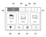
図2は操作表示部108に表示する標準ホーム画面を示す図である。タブ201は標準ホーム画面に対応したタブである。タブ202、203、および204はそれぞれカスタムホーム画面に対応したタブ(カスタムタブ)である。以下、「タブ」という表現は、当該タブに対応するメニュー画面を表すこともある。ユーザはタブを押下することでホーム画面を切り替えることができる。また、タブ201のタブの色を他のタブの色と変えることにより、現在表示されているタブ(現在タブ)201の画面(即ち、標準ホーム画面)が表示していることを示す。標準ホーム画面はコピーメニューボタン205、スキャンメニューボタン206、プリントメニューボタン207、LANボタン208、ワイヤレスコネクトボタン209、設定ボタン210、およびヒントボタン211を有する。ユーザが各ボタンを押下することにより、各ボタンに対応した画面へと遷移する。具体的には例えば、コピーメニューボタン205が押されたら、コピーの設定を入力する領域や、コピーの実行を指示するための画面が表示される。標準ホーム画面には、後述のカスタムホーム画面と異なり、ユーザが任意に選択することなく予め決まったボタンが表示されるものとする。しかしこの形態に限定されず。標準ホーム画面に表示されるボタンも、ユーザが任意に選択や変更可能な形態であっても良い。
2 is a diagram showing a standard home screen displayed on the
図3は操作表示部108に表示するタブ202のカスタムホーム画面を示す図である。タブ202のタブの色を他のタブの色と変えることにより、現在タブ202のカスタムホーム画面を表示していることを示す。タブ202のカスタムホーム画面は、カスタムメニュー(画面)305、306、および307を有しており、それぞれのメニューはユーザがカスタム可能なメニューであり、各メニュー位置に表示する機能を指定できる。本図においては、カスタムメニュー305に「標準コピー」、カスタムメニュー306に「両面コピー」、またカスタムメニュー307に「原稿をパソコンに保存」がそれぞれ設定されている。両面コピーとは、記録媒体の表側、裏側に印刷を行う両面印刷機能を適用したコピーのことである。なおカスタムホーム画面には、標準ホーム画面と異なり、各メニューから実行される処理の設定を紐づけたメニューを登録可能である。すなわち例えば、コピーメニューボタン205から実行されるコピーにおいては、当該コピーが両面コピーか片面コピーかはコピーメニューボタン205が押された後に別途設定する必要がある。しかし、カスタムメニュー306から実行されるコピーにおいては、当該コピーが両面コピーか片面コピーかをカスタムメニュー306が押された後に別途設定する必要がない。また、各ホーム画面毎に、ログイン情報やcookie情報が紐づけられて保存されても良い。また、各カスタムホーム画面にはロックを設定することができる。本実施形態ではロックとは、パスワード(認証情報)入力画面に対する正確なパスワードの入力無しでは、カスタムホーム画面を表示しないようにするための制御を指す。ロックが設定されていないカスタムホーム画面は、当該カスタムホーム画面に対応するタブが操作されたら、パスワード入力画面の表示無しに当該カスタムホーム画面が表示される。カスタムホーム画面のカスタムメニューの設定およびロック設定は図2の設定ボタン210から行うことができる。
Figure 3 is a diagram showing the custom home screen of
図4は操作表示部108に表示するタブ202のロック画面を示す図である。ユーザがロック制御されたカスタムホーム画面に対応するタブであるタブ202を選択したとき、カスタムホーム画面は表示されず、図4に示す画面が表示される。ユーザがロック解除ボタン401を押下することでパスワード入力画面が表示され、入力したパスワードが正確なパスワードと一致した場合、タブ202のカスタムホーム画面が表示される。なお正確なパスワードは、タブ毎に設定される。本実施形態においてロック状態とは、選択されたタブ(対象タブ)に対応するメニュー画面に対するユーザ操作が制限された状態である。例えば、図4のように選択されたタブに対応するメニュー画面を表示しない状態である。または、選択されたタブに対応するメニュー画面が表示されるが、表示内容を変更できない状態でも良い。
Figure 4 is a diagram showing the lock screen of
本実施形態では、現在表示中のタブ202のカスタムホーム画面から別のタブのメニューを表示後、再度タブ202が押下された場合、ロック画面は表示せずユーザはパスワード入力することなくタブ202のカスタムホーム画面を表示させる。
In this embodiment, when
図5は操作表示部108に表示するロック解除状態(ロック解除中)のカスタムホーム画面である。ロック解除中アイコン501は現在表示されているタブ202に対応するカスタムホーム画面のロック設定が解除されていることを示す。
Figure 5 shows a custom home screen in an unlocked state (unlocked) displayed on the
本実施形態では、ユーザはロック解除中アイコン(即ち、本図ではタブ202)を押下することでタブをロックできる。なお、ロック設定が無効なタブではロック解除中アイコン501は表示されず、現在表示されているカスタムホーム画面のタブを押下しても処理は行われない。尚、タブのロック設定を有効にするか、または無効にするかの設定は予めタブごとに行われているものとする。タブのロック設定を有効にするか、または無効にするかの設定は、例えば、設定ボタン210から行うことができるようにすればよい。
In this embodiment, the user can lock a tab by pressing the unlocked icon (i.e.,
<フローチャート>
図6は本実施形態のロック解除シーケンスを説明するためのフローチャートである。本図を用いて、ユーザがタブのロックを解除する処理の流れについて説明していく。本フローチャートに示される一連の処理は、MFP100のCPU101がROM102に記憶されているプログラムコードをRAM103に展開し実行することによって行われる。尚、以下の各処理の説明における「S」はフローチャートにおけるステップであることを意味し、以降の実施形態においても同様である。本処理はユーザがカスタムホーム画面のタブを押下する場合に実行される。また、本処理は、操作表示部108がタッチなどユーザの操作を検知することで開始される。
<Flowchart>
FIG. 6 is a flowchart for explaining the unlock sequence of this embodiment. The flow of processing for a user to unlock a tab will be explained using this diagram. A series of processing shown in this flowchart is performed by the
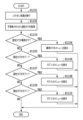
まずS601において、CPU101は、ユーザによって押下されたタブを検知する。S602においてCPU101は、タブのロックフラグがONかを判定する。タブのロックフラグは各タブごとに個別に用意され、タブのロック操作時にONになる。タブのロック操作に関する詳細は後述する。ロックフラグがOFFの場合、S607においてCPU101は、タブのメニューを表示する。なお、ロック設定が無効なタブのロックフラグは常にOFFである。前述でも説明したが、タブのロック設定を有効にするか、または無効にするかの設定は予めタブごとに設定されているものとする。
First, in S601,
ロックフラグがONの場合、S603においてCPU101は、図4に示すようなロック画面を表示する。S604においてCPU101は、ユーザからのパスワード入力を検知するとS605においてパスワードが一致しているかの判定を行う。パスワードが不一致だった場合は再度S603においてロック画面を表示する。パスワードが一致した場合はS606においてロックフラグをOFFに設定後、S607においてタブのメニューを表示する。
If the lock flag is ON, in S603, the
S608においてユーザ操作によって他のタブへ切替えが行われた場合、CPU101はS606においてロックフラグをOFFにした切り替え前のタブに関してロックフラグの状態をOFFのまま維持する。これにより、S601において再度タブ押下を検知した際はS602においてロックフラグがOFFの判定となり、ユーザはパスワード入力をせずタブのメニューを表示させることができる。以上が、タブのロックを解除する際の処理の流れである。
If the user switches to another tab in S608, the
次に、ユーザがタブをロックする際の処理を説明する。 Next, we'll explain what happens when the user locks a tab.
図7はユーザがタブをロックする際の処理シーケンスを説明するためのフローチャートである。本フローチャートに示される一連の処理は、MFP100のCPU101がROM102に記憶されているプログラムコードをRAM103に展開し実行することによって行われる。本処理は、ユーザによるパスワード認証等の解除操作によってタブが解除状態になることで開始される。
Figure 7 is a flowchart for explaining the processing sequence when a user locks a tab. The series of processes shown in this flowchart is performed by the
S701においてCPU101は、操作表示部108に所定のタブのメニューを表示している。S702においてCPU101は、操作表示部108に現在メニューを表示しているタブの押下を検知したかどうか判定する。本ステップにおいてCPU101は、例えば予め決定した時間が経過するまでにタブの押下を検知していないと判定した場合は、本フローチャートの処理を終了する。一方、時間内にタブの押下を検知したと判定した場合は、S703において当該タブのロック設定が有効かを判定する。前述でも説明したが、タブのロック設定を有効にするか、または無効にするかの設定は予めタブごとに設定されているものとする。当該タブのロック設定が無効の場合は処理を終了する。タブのロック設定が有効だった場合、S704においてロック確認画面を表示する。ロック確認画面は例えば図8の表示画面850である。一方、ロック確認画面においてユーザはタブをロックするか否かを選択する。CPU101は、ロック確認画面においてユーザ操作によりロックしない選択を検知した場合、S701に処理を戻す。S705においてロックする選択を検知した場合、S706においてCPU101は、ロックフラグをONに設定し、S707においてロック中画面を表示後、本フローチャートの処理を終了する。以上が、ユーザによってタブをロックする場合の処理の流れである。
In S701, the
次に操作表示部108のバックライトオフ時の画面遷移について説明する。操作表示部108のバックライトはユーザによって操作表示部108が操作されて画面が表示された場合やMFP100の電源がオンされて操作表示部108に画面が表示された場合にオン状態となる。そしてバックライトがオン状態においてユーザによる操作が一定時間検知されなければ消費電力を低減させるためにオフ状態になるものである。すなわち、バックライトがオンである状態とは、操作表示部108に画面が表示されている状態であり、バックライトがオフである状態とは、操作表示部108に画面が表示されておらず、省電力の状態である。
Next, we will explain the screen transition when the backlight of the
図8はバックライトオフ時の画面遷移を示すフローチャートである。本フローチャートに示される一連の処理は、MFP100のCPU101がROM102に記憶されているプログラムコードをRAM103に展開し実行することによって行われる。
Figure 8 is a flowchart showing the screen transition when the backlight is off. The series of processes shown in this flowchart are performed by the
まず、S801においてCPU101は、バックライトオフタイマの満了を検知する。すなわち、CPU101は、所定の時間が経過したらバックライトをオフにするため、バックライトオフ用タイマを起動して操作表示部108に対するユーザ操作がなくなってからの経過時間をカウントしている。CPU101は、S801において当該所定の時間が経過したことを検知する。タイマの設定時間に関しては、ユーザによって予め設定されているものとする。
First, in S801, the
S802においてCPU101は現在タブのロック設定を取得する。ここでの現在タブとは、現在表示されているタブであり、バックライトオフ状態においてはバックライトがオフになる前に最後に表示されていたタブである。なお、バックライトがオフになる条件に達した場合とは、操作表示部108に対するユーザ操作がなくなってから所定の時間が経過した場合(すなわち、バックライトオフ用タイマを起動してから所定の時間が経過した場合)である。
In S802, the
S803においてCPU101は、現在タブのロック設定が有効か否かを判定する。現在タブのロック設定が有効であると判定された場合、S804においてCPU101は、現在タブのロック制をロック状態に設定するロック制御を実行し、表示画面を現在タブのロック中画面に遷移させる。その後、S805においてバックライトをオフにして本フローチャートの処理を終了する。尚、S804の処理は、バックライトオン時に行うことも可能である、即ち、S803において現在タブのロック設定が有効である場合であっても、S804を経由せずにバックライトをオフにする。その後バックライトオン時にロック設定が有効であるタブついては現在タブのロック中画面を表示制御するようにしてもよい。つまり、ロック中画面はバックライトオフの段階で表示させてもよいし、バックライトオン時に表示させてもよい。
In S803, the
S803においてCPU101は、現在タブのロック設定が無効であると判定した場合、S805においてCPU101は、バックライトをオフにする。その後、CPU101は本フローチャートの処理を終了する。
If the
以上、図8のフローチャートの処理により、ロック設定が有効なタブ以下の階層の画面でバックライトをオフにした場合、バックライトをオンにした時に操作表示部108にはロック中画面が表示される。一方、ロック設定が無効なタブ以下の階層の画面でバックライトをオフにした場合、バックライトをオンにした時には操作表示部108にはバックライトオフ前に表示していた画面が表示される。これにより、ロック設定が有効な現在タブについてのバックライトオフ時のセキュリティを確保することができる。尚、図8のフローチャートの処理は現在表示されている現在タブに対しての処理であるため、他のタブに関しては、タブロックは適用されないため操作性を確保することができる。
As described above, when the backlight is turned off on a screen in a hierarchy below a tab for which the lock setting is enabled, the operation and
次に、CPU101が操作表示部108のバックライトをオフにした時にロック設定が有効となってるタブを全てロック状態にする方法を説明する。
Next, we will explain how to lock all tabs for which the lock setting is enabled when the
図9はバックライトオフ時のロック処理シーケンスを説明するためのフローチャートである。本フローチャートに示される一連の処理は、MFP100のCPU101がROM102に記憶されているプログラムコードをRAM103に展開し実行することによって行われる。
Figure 9 is a flowchart for explaining the lock processing sequence when the backlight is off. The series of processes shown in this flowchart are performed by the
S901においてCPU101は、バックライトオフタイマの満了を検知すると、S902においてインデックスiを1に初期化する。S903においてCPU101は、インデックスiがカスタムタブ数以下かの判定を行う。S903においてインデックスiがカスタムタブ数以下だった場合、S904においてCPU101は、i番目のカスタムタブのロック設定が有効かを判定する。i番目のカスタムタブのロック設定が有効だった場合、S905においてCPU101は、i番目のカスタムタブのロックフラグをONに設定する。
When the
S904においてi番目のカスタムタブのロック設定が無効だった場合、およびS905においてi番目のカスタムタブのロックフラグをONに設定した後、S906においてCPU101は、インデックスiに1を加算する。S906を実施後、再度S903においてインデックスiがカスタムタブ数以下かの判定を行う。S903においてインデックスiがタブ数よりも大きくなった場合、CPU101は本フローチャートの処理を終了する。これにより、インデックスiがカスタムタブ数と同じ値になるまで、タブの番号が若い方から順にタブをロックすることができる。即ち、ロック設定が有効なタブをバックライトオフのタイミングですべてロック状態にすることができる。この処理により、ユーザが操作を終えた際に、ログアウト等の操作を失念したとしても、一定時間経過することでロック状態にすべきタブをロックすることができる。これにより、図8で説明した現在タブのみをロックする処理と比べてよりセキュリティ性を向上させることができる。
If the lock setting of the i-th custom tab is invalid in S904, and after the lock flag of the i-th custom tab is set to ON in S905, the
次に図10、図11を用いて本実施形態のタブ切り替え処理を説明する。本実施形態のタブ切り替え処理は、MFP100に対してソフトオンされた(MFP100が電源オン操作に応じて起動した)時、標準タブのメニュー画面を表示するのではなく、前回MFPが使用された際の最後に表示されていたタブを表示するものである。以下、最後に表示されていたタブを対象タブとも呼ぶ。尚、以下のタブ切り替えの説明では、図2に示すように標準タブ、タブ1、タブ2、およびタブ3の4つのタブを有するような表示画面について説明していく。
Next, the tab switching process of this embodiment will be described with reference to Figures 10 and 11. In the tab switching process of this embodiment, when the
図10はタブ切替えのシーケンスを説明するフローチャートである。本フローチャートに示される一連の処理は、MFP100のCPU101がROM102に記憶されているプログラムコードをRAM103に展開し実行することによって行われる。
Figure 10 is a flowchart explaining the sequence of tab switching. The series of processes shown in this flowchart are performed by the
S1001においてCPU101は、タブの切り替えを検知する。S1002においてCPU101は、切替え後のタブを不揮発メモリに保存する。本処理で保存するタブを現在タブと呼ぶ。その後、S1003において切替え後のタブに対応したメニューを表示し、CPU101は本フローチャートの処理を終了する。例えば、CPU101は、切替え後のタブがタブ2である場合、S1003において操作表示部108にタブ2に対応するメニュー画面を表示する。
In S1001,
図11はソフトオン時の画面表示シーケンスを説明するフローチャートである。本フローチャートに示される一連の処理は、MFP100のCPU101がROM102に記憶されているプログラムコードをRAM103に展開し実行することによって行われる。本処理は電源がオフされた状態(電源オフ状態)で電源ボタンが押下されたことにより開始する。
Figure 11 is a flowchart explaining the screen display sequence during soft-on. The series of processes shown in this flowchart are performed by the
S1101においてCPU101はソフトオン処理を実行する。すなわち、CPU101は、MFP100を電源オンに応じて起動させる。次にS1102においてCPU101は、図10のS1002において不揮発メモリに保存した現在タブを取得する。
In S1101, the
S1103においてCPU101は、現在タブが標準タブかカスタムタブかを判定する。現在タブが標準タブの場合(S1103においてYESと判定された場合)、S1104においてCPU101は、標準タブのメニューを操作表示部108に表示し、本フローチャートの処理を終了する。現在タブが標準タブでない場合(S1103においてNOと判定された場合)、S1105においてCPU101は、現在タブがタブ1かを判定する。現在タブがタブ1の場合(S1105においてYESと判定された場合)、S1106においてCPU101は、タブ1のメニュー画面を操作表示部108に表示し、本フローチャートの処理を終了する。現在タブがタブ1でない場合(S1105においてNOと判定された場合)、S1107においてCPU101は、現在タブがタブ2かを判定する。現在タブがタブ2の場合(S1107においてYESと判定された場合)、S1108においてCPU101は、タブ2のメニューを操作表示部108に表示する。その後、本フローチャートの処理を終了する。現在タブがタブ2でない場合(S1107においてNOと判定された場合)、S1109においてCPU101は、現在タブがタブ3かを判定する。現在タブがタブ3の場合(S1109においてYESと判定された場合)、S1110においてCPU101は、タブ3のメニューを操作表示部108に表示し、本フローチャートの処理を終了する。現在タブがタブ3でない場合(S1109においてNOと判定された場合)、CPU101は本フローチャートの処理を終了する。このような処理によって、前回MFP100を電源オフした時に表示されていたタブを、MFP100の電源オン時に表示することができる。
In S1103, the
尚、図11のS1104、S1106、S1108、およびS1110において当該タブのロック設定が有効であった場合には、当該タブに対応するメニュー画面をロック状態に設定し、ロック状態の画面を表示する。そして、CPU101は、ユーザによって正しいパスワードが入力された場合に当該タブのメニュー画面を表示する。
If the lock setting for the tab is enabled in steps S1104, S1106, S1108, and S1110 in FIG. 11, the menu screen corresponding to the tab is set to a locked state, and the locked state screen is displayed. Then, when the user inputs the correct password, the
以上、図10、および図11で説明した処理を行うことで表示画面のセキュリティを向上させることができる。具体的には、MFP100の操作表示部108のバックライトがオフになる条件に達した場合、ロック設定の有無に基づいて表示中のタブをロック状態に制御することができる。
By carrying out the processes described above with reference to Figures 10 and 11, it is possible to improve the security of the display screen. Specifically, when the conditions for turning off the backlight of the
<<その他の実施形態>>
上述の本実施形態においてはMFP100の表示画面を例に説明したが、これに限らず操作表示部を有していれば、どのような機器に適用してもよい。また例えば、MFP100の設定を実行したりMFP100に各種処理を実行させるための上述の各画面を、MFP100がMFP100と通信している他の装置(スマートフォンやPC)などに表示させても良い。そして、当該他の装置に表示される画面において、本開示を適用しても良い。
<<Other embodiments>>
In the above embodiment, the display screen of the
また、上述した実施形態は、以下の処理を実行することによっても実現される。すなわち、上述した実施形態の機能を実現するソフトウェア(プログラム)を、ネットワーク又は各種記憶媒体を介してシステム或いは装置に供給し、そのシステム或いは装置のコンピュータ(CPUやMPU等)がプログラムを読み出して実行する処理である。また、プログラムは、1つのコンピュータで実行させても、複数のコンピュータで連動させて実行させるようにしてもよい。また、上記した処理の全てをソフトウェアで実現する必要はなく、処理の一部または全部をASIC等のハードウェアで実現するようにしてもよい。また、CPUも1つのCPUで全ての処理を行うものに限らず、複数のCPUが適宜連携をしながら処理を行うものとしてもよい。 The above-described embodiments can also be realized by executing the following process. That is, software (programs) that realize the functions of the above-described embodiments are supplied to a system or device via a network or various storage media, and the computer (CPU, MPU, etc.) of the system or device reads and executes the program. The program may be executed by one computer, or may be executed by multiple computers in cooperation with each other. It is not necessary to realize all of the above-described processes by software, and some or all of the processes may be realized by hardware such as an ASIC. The CPU is also not limited to one that performs all processes by one CPU, and multiple CPUs may perform processes in cooperation with each other as appropriate.
また、コンピュータが読み出したプログラムコードを実行することにより、前述した実施例の機能が実現されるだけでない。そのプログラムコードの指示に基づき、コンピュータ上で稼動しているOSなどが実際の処理の一部または全部を行い、その処理によって前述した実施形態の機能が実現される場合も含まれる。 Furthermore, the functions of the above-mentioned embodiments are not only realized by the computer executing the program code that it has read. It also includes cases where an OS running on a computer performs some or all of the actual processing based on the instructions of the program code, and the functions of the above-mentioned embodiments are realized through that processing.
また、本開示は、以下の構成を含む。 This disclosure also includes the following:
(構成1)
画像データを記録媒体に印刷する印刷機能と、原稿を読み取る読取機能を少なくとも含む複数の機能を実行可能であるインクジェットプリンタであって、
表示部と、
前記印刷機能の実行を指示するためのボタンと前記読取機能の実行を指示するためのボタンを含む第1のホーム画面と、前記印刷機能の実行を指示するためのボタンと両面印刷機能の実行を指示するためのボタンを含む第2のホーム画面を切り替えて前記表示部に表示することが可能な表示制御手段と、
を備え、
前記表示制御手段は、前記第1のホーム画面が前記表示部に表示された状態で前記インクジェットプリンタの電源がオフ状態に移行し、その後、前記インクジェットプリンタの電源がオン状態に移行した場合、前記第1のホーム画面を前記表示部に表示し、前記第2のホーム画面が前記表示部に表示された状態で前記インクジェットプリンタの電源がオフ状態に移行し、その後、前記インクジェットプリンタの電源がオン状態に移行した場合、前記第2のホーム画面を前記表示部に表示することを特徴とするインクジェットプリンタ。
(Configuration 1)
An inkjet printer capable of executing a plurality of functions including at least a printing function of printing image data on a recording medium and a reading function of reading an original,
A display unit;
a display control means for switching between a first home screen including a button for instructing execution of the printing function and a button for instructing execution of the reading function and a second home screen including a button for instructing execution of the printing function and a button for instructing execution of a double-sided printing function and displaying the first home screen on the display unit;
Equipped with
The display control means displays the first home screen on the display unit when the inkjet printer is turned off while the first home screen is displayed on the display unit and then the inkjet printer is turned on, and displays the second home screen on the display unit when the inkjet printer is turned off while the second home screen is displayed on the display unit and then the inkjet printer is turned on.
100 MFP
101 CPU
108 操作表示部
100 MFP
101 CPU
108 Operation display section
Claims (14)
表示部と、
第1のモードのホーム画面と、複数の第2のモードのホーム画面と、を切り替えて前記表示部に表示することが可能な表示制御手段と、
前記複数の第2のモードのホーム画面の各ホーム画面に対して認証情報を設定することが可能な設定手段と、
を備え、
前記第1のモードのホーム画面は、コピー機能の実行を指示するためのボタンとスキャン機能の実行を指示するためのボタンとLANに関するボタンを含み、前記複数の第2のモードのホーム画面のうち少なくとも1つのホーム画面は、コピー機能の実行を指示するためのボタンと両面コピー機能の実行を指示するためのボタンを含み、かつLANに関するボタンを含まず、
前記複数の第2のモードのホーム画面のうち少なくとも1つのホーム画面は、さらに、前記コピー機能に関連する第1画像と、前記両面コピー機能に関連する画像であって前記第1画像とは異なる第2画像とを含み、
前記表示制御手段は、前記複数の第2のモードのホーム画面のうち所定のホーム画面に対して入力された情報が、前記設定手段によって設定された前記所定のホーム画面の認証情報を満たす場合に、前記所定のホーム画面を表示し、
前記第1のモードのホーム画面が前記表示部に表示された状態で前記インクジェットプリンタの電源がオフ状態に移行し、その後、前記インクジェットプリンタの電源がオン状態に移行した場合、前記インクジェットプリンタの電源がオフ状態へ移行時に前記第1のモードのホーム画面が表示されていたことに基づいて前記第1のモードのホーム画面を前記表示部に表示し、
前記第2のモードのホーム画面が前記表示部に表示された状態で前記インクジェットプリンタの電源がオフ状態に移行し、その後、前記インクジェットプリンタの電源がオン状態に移行した場合、前記インクジェットプリンタの電源がオフ状態へ移行時に前記第2のモードのホーム画面が表示されていたことに基づいて前記第2のモードのホーム画面を前記表示部に表示する
ことを特徴とするインクジェットプリンタ。 An inkjet printer capable of performing multiple functions, comprising:
A display unit;
a display control means for switching between a home screen of a first mode and a plurality of home screens of a second mode and displaying the home screens on the display unit;
a setting means for setting authentication information for each of the home screens of the second mode;
Equipped with
the home screen of the first mode includes a button for instructing execution of a copy function, a button for instructing execution of a scan function, and a button related to a LAN, and at least one home screen of the plurality of home screens of the second mode includes a button for instructing execution of the copy function and a button for instructing execution of a double-sided copy function, but does not include a button related to a LAN;
At least one home screen among the plurality of second mode home screens further includes a first image related to the copy function and a second image related to the double-sided copy function and different from the first image;
the display control means displays a predetermined home screen among the plurality of home screens of the second mode when information input for the predetermined home screen satisfies authentication information for the predetermined home screen set by the setting means;
when the inkjet printer is turned off with the home screen of the first mode displayed on the display unit and then turned on, the home screen of the first mode is displayed on the display unit based on the fact that the home screen of the first mode was displayed when the inkjet printer was turned off;
an inkjet printer comprising: a display unit configured to display a home screen of the second mode on a display unit; a power supply unit configured to supply power to the inkjet printer; a power supply unit configured to supply power to the inkjet printer;
ことを特徴とする請求項1に記載のインクジェットプリンタ。 2. The inkjet printer according to claim 1, wherein a number of buttons, including a button for instructing execution of the copy function, displayed on the home screen in the first mode is different from a number of buttons displayed on the home screen in the second mode.
ことを特徴とする請求項1に記載のインクジェットプリンタ。 2. The inkjet printer according to claim 1, wherein the display control means, when displaying a button indicating the copy function specified by the user on the home screen of the second mode, displays a button indicating the copy function including a name indicating the copy function, and when displaying a button indicating the double-sided copy function specified by the user on the home screen of the second mode, displays a button indicating the double-sided copy function including a name indicating the double-sided copy function.
ことを特徴とする請求項1に記載のインクジェットプリンタ。 2. The inkjet printer according to claim 1, wherein the power supply is switched to an ON state when the inkjet printer is soft-on and started up.
第1のモードのホーム画面と、複数の第2のモードのホーム画面と、を切り替えて前記表示部に表示することが可能な表示制御ステップと、
前記複数の第2のモードのホーム画面の各ホーム画面に対して認証情報を設定することが可能な設定ステップと、
を備え、
前記第1のモードのホーム画面は、コピー機能の実行を指示するためのボタンとスキャン機能の実行を指示するためのボタンとLANに関するボタンを含み、前記複数の第2のモードのホーム画面のうち少なくとも1つのホーム画面は、コピー機能の実行を指示するためのボタンと両面コピー機能の実行を指示するためのボタンを含み、かつLANに関するボタンを含まず、
前記複数の第2のモードのホーム画面のうち少なくとも1つのホーム画面は、さらに、前記コピー機能に関連する第1画像と、前記両面コピー機能に関連する画像であって前記第1画像とは異なる第2画像とを含み、
前記表示制御ステップは、前記複数の第2のモードのホーム画面のうち所定のホーム画面に対して入力された情報が、前記設定ステップによって設定された前記所定のホーム画面の認証情報を満たす場合に、前記所定のホーム画面を表示し、
前記第1のモードのホーム画面が前記表示部に表示された状態で前記インクジェットプリンタの電源がオフ状態に移行し、その後、前記インクジェットプリンタの電源がオン状態に移行した場合、前記インクジェットプリンタの電源がオフ状態へ移行時に前記第1のモードのホーム画面が表示されていたことに基づいて前記第1のモードのホーム画面を前記表示部に表示し、
前記第2のモードのホーム画面が前記表示部に表示された状態で前記インクジェットプリンタの電源がオフ状態に移行し、その後、前記インクジェットプリンタの電源がオン状態に移行した場合、前記インクジェットプリンタの電源がオフ状態へ移行時に前記第2のモードのホーム画面が表示されていたことに基づいて前記第2のモードのホーム画面を前記表示部に表示する
ことを特徴とする制御方法。 A method for controlling an inkjet printer capable of executing a plurality of functions and having a display unit, comprising the steps of:
a display control step of switching between a home screen of a first mode and a plurality of home screens of a second mode and displaying them on the display unit;
a setting step of setting authentication information for each of the home screens of the plurality of second mode home screens;
Equipped with
the home screen of the first mode includes a button for instructing execution of a copy function, a button for instructing execution of a scan function, and a button related to a LAN, and at least one home screen of the plurality of home screens of the second mode includes a button for instructing execution of the copy function and a button for instructing execution of a double-sided copy function, but does not include a button related to a LAN;
At least one home screen among the plurality of second mode home screens further includes a first image related to the copy function and a second image related to the double-sided copy function and different from the first image;
The display control step displays a predetermined home screen among the plurality of home screens of the second mode when information input for the predetermined home screen satisfies authentication information for the predetermined home screen set in the setting step, and
when the inkjet printer is turned off with the home screen of the first mode displayed on the display unit and then turned on, the home screen of the first mode is displayed on the display unit based on the fact that the home screen of the first mode was displayed when the inkjet printer was turned off;
a control method characterized in that, when the inkjet printer is turned off while the home screen of the second mode is displayed on the display unit, and then the inkjet printer is turned on, the home screen of the second mode is displayed on the display unit based on the fact that the home screen of the second mode was displayed when the inkjet printer was turned off.
Priority Applications (2)
| Application Number | Priority Date | Filing Date | Title |
|---|---|---|---|
| JP2024071464A JP7686836B2 (en) | 2022-10-26 | 2024-04-25 | Inkjet printer |
| JP2025084875A JP2025118984A (en) | 2022-10-26 | 2025-05-21 | Inkjet printer |
Applications Claiming Priority (2)
| Application Number | Priority Date | Filing Date | Title |
|---|---|---|---|
| JP2022171518A JP7480251B1 (en) | 2022-10-26 | 2022-10-26 | Inkjet printer, inkjet printer control method, and program |
| JP2024071464A JP7686836B2 (en) | 2022-10-26 | 2024-04-25 | Inkjet printer |
Related Parent Applications (1)
| Application Number | Title | Priority Date | Filing Date |
|---|---|---|---|
| JP2022171518A Division JP7480251B1 (en) | 2022-10-26 | 2022-10-26 | Inkjet printer, inkjet printer control method, and program |
Related Child Applications (1)
| Application Number | Title | Priority Date | Filing Date |
|---|---|---|---|
| JP2025084875A Division JP2025118984A (en) | 2022-10-26 | 2025-05-21 | Inkjet printer |
Publications (2)
| Publication Number | Publication Date |
|---|---|
| JP2024102158A JP2024102158A (en) | 2024-07-30 |
| JP7686836B2 true JP7686836B2 (en) | 2025-06-02 |
Family
ID=90833509
Family Applications (3)
| Application Number | Title | Priority Date | Filing Date |
|---|---|---|---|
| JP2022171518A Active JP7480251B1 (en) | 2022-10-26 | 2022-10-26 | Inkjet printer, inkjet printer control method, and program |
| JP2024071464A Active JP7686836B2 (en) | 2022-10-26 | 2024-04-25 | Inkjet printer |
| JP2025084875A Pending JP2025118984A (en) | 2022-10-26 | 2025-05-21 | Inkjet printer |
Family Applications Before (1)
| Application Number | Title | Priority Date | Filing Date |
|---|---|---|---|
| JP2022171518A Active JP7480251B1 (en) | 2022-10-26 | 2022-10-26 | Inkjet printer, inkjet printer control method, and program |
Family Applications After (1)
| Application Number | Title | Priority Date | Filing Date |
|---|---|---|---|
| JP2025084875A Pending JP2025118984A (en) | 2022-10-26 | 2025-05-21 | Inkjet printer |
Country Status (2)
| Country | Link |
|---|---|
| US (2) | US12192417B2 (en) |
| JP (3) | JP7480251B1 (en) |
Families Citing this family (1)
| Publication number | Priority date | Publication date | Assignee | Title |
|---|---|---|---|---|
| JP7676348B2 (en) | 2022-10-26 | 2025-05-14 | キヤノン株式会社 | Inkjet printer, inkjet printer control method, and program |
Citations (8)
| Publication number | Priority date | Publication date | Assignee | Title |
|---|---|---|---|---|
| JP2006191328A (en) | 2005-01-05 | 2006-07-20 | Ricoh Co Ltd | Operation unit of image forming apparatus |
| JP2007060033A (en) | 2005-08-22 | 2007-03-08 | Ricoh Co Ltd | Multifunction image forming apparatus, screen display mode setting method, program, and recording medium |
| US20090092106A1 (en) | 2007-10-04 | 2009-04-09 | Kabushiki Kaisha Toshiba | Wireless lan setting system in an image forming apparatus, and a wireless lan setting method |
| JP2013025561A (en) | 2011-07-21 | 2013-02-04 | Brother Ind Ltd | Data input device, control method for data input device, and program |
| JP2017059050A (en) | 2015-09-17 | 2017-03-23 | キヤノン株式会社 | Information processing apparatus, control method therefor, and program |
| JP2017211729A (en) | 2016-05-23 | 2017-11-30 | キヤノン株式会社 | Communication device, communication method, and program |
| JP2020052973A (en) | 2018-09-28 | 2020-04-02 | ブラザー工業株式会社 | Display control device, display control method and program |
| JP2020112652A (en) | 2019-01-10 | 2020-07-27 | 京セラドキュメントソリューションズ株式会社 | Image forming apparatus |
Family Cites Families (18)
| Publication number | Priority date | Publication date | Assignee | Title |
|---|---|---|---|---|
| JP2002312092A (en) * | 2001-04-16 | 2002-10-25 | Sharp Corp | Graphical user interface creation device |
| JP2012093612A (en) | 2010-10-28 | 2012-05-17 | Sharp Corp | Operation device and image forming apparatus |
| US9122862B2 (en) * | 2011-04-13 | 2015-09-01 | Lenovo (Singapore) Pte. Ltd. | Password input method using visual object |
| JP2013014079A (en) | 2011-07-04 | 2013-01-24 | Canon Inc | Information processing apparatus, control method therefor, and program |
| EP2615564A1 (en) * | 2012-01-11 | 2013-07-17 | LG Electronics | Computing device for performing at least one function and method for controlling the same |
| JP6442174B2 (en) | 2014-07-03 | 2018-12-19 | キヤノン株式会社 | PROCESSING DEVICE, PROCESSING DEVICE CONTROL METHOD, PROGRAM |
| JP6378567B2 (en) | 2014-07-23 | 2018-08-22 | キヤノン株式会社 | Apparatus, method, program |
| KR102308645B1 (en) * | 2014-12-29 | 2021-10-05 | 삼성전자주식회사 | User termincal device and methods for controlling the user termincal device thereof |
| JP5931242B1 (en) | 2015-03-20 | 2016-06-08 | ヤフー株式会社 | Terminal device, information transmission method, and information transmission program |
| US10182169B2 (en) * | 2016-06-02 | 2019-01-15 | Ricoh Company, Ltd. | Information processing apparatus, information processing method, and non-transitory recording medium |
| JP6880801B2 (en) | 2017-02-10 | 2021-06-02 | ブラザー工業株式会社 | Display control device, control method of display control device, and control program of display control device |
| JP7119408B2 (en) * | 2018-02-15 | 2022-08-17 | コニカミノルタ株式会社 | Image processing device, screen handling method, and computer program |
| JP7067201B2 (en) * | 2018-03-30 | 2022-05-16 | ブラザー工業株式会社 | Screen creation program, information processing device and screen creation method |
| JP7210977B2 (en) | 2018-09-28 | 2023-01-24 | ブラザー工業株式会社 | image forming device |
| JP2020088412A (en) | 2018-11-15 | 2020-06-04 | キヤノン株式会社 | Image processing apparatus, control method of image processing apparatus, and program |
| JP7183859B2 (en) | 2019-02-25 | 2022-12-06 | ブラザー工業株式会社 | FUNCTION EXECUTION DEVICE, FUNCTION EXECUTION METHOD AND FUNCTION EXECUTION PROGRAM |
| JP7467200B2 (en) | 2020-03-30 | 2024-04-15 | キヤノン株式会社 | Information processing device, control method, program, and information processing system |
| JP7619021B2 (en) | 2020-11-26 | 2025-01-22 | ブラザー工業株式会社 | Scanner, control program |
-
2022
- 2022-10-26 JP JP2022171518A patent/JP7480251B1/en active Active
-
2023
- 2023-10-19 US US18/490,479 patent/US12192417B2/en active Active
-
2024
- 2024-04-25 JP JP2024071464A patent/JP7686836B2/en active Active
- 2024-10-25 US US18/927,672 patent/US20250055950A1/en active Pending
-
2025
- 2025-05-21 JP JP2025084875A patent/JP2025118984A/en active Pending
Patent Citations (8)
| Publication number | Priority date | Publication date | Assignee | Title |
|---|---|---|---|---|
| JP2006191328A (en) | 2005-01-05 | 2006-07-20 | Ricoh Co Ltd | Operation unit of image forming apparatus |
| JP2007060033A (en) | 2005-08-22 | 2007-03-08 | Ricoh Co Ltd | Multifunction image forming apparatus, screen display mode setting method, program, and recording medium |
| US20090092106A1 (en) | 2007-10-04 | 2009-04-09 | Kabushiki Kaisha Toshiba | Wireless lan setting system in an image forming apparatus, and a wireless lan setting method |
| JP2013025561A (en) | 2011-07-21 | 2013-02-04 | Brother Ind Ltd | Data input device, control method for data input device, and program |
| JP2017059050A (en) | 2015-09-17 | 2017-03-23 | キヤノン株式会社 | Information processing apparatus, control method therefor, and program |
| JP2017211729A (en) | 2016-05-23 | 2017-11-30 | キヤノン株式会社 | Communication device, communication method, and program |
| JP2020052973A (en) | 2018-09-28 | 2020-04-02 | ブラザー工業株式会社 | Display control device, display control method and program |
| JP2020112652A (en) | 2019-01-10 | 2020-07-27 | 京セラドキュメントソリューションズ株式会社 | Image forming apparatus |
Non-Patent Citations (1)
| Title |
|---|
| LP-S8180シリーズ LP-S7180シリーズ ユーザーズガイド[online],2020年,[2024年11月12日検索], <https://www2.epson.jp/support/manual/NPD647103_UG_JA.PDF> |
Also Published As
| Publication number | Publication date |
|---|---|
| JP2025118984A (en) | 2025-08-13 |
| US20240146851A1 (en) | 2024-05-02 |
| US12192417B2 (en) | 2025-01-07 |
| JP7480251B1 (en) | 2024-05-09 |
| JP2024102158A (en) | 2024-07-30 |
| JP2024067040A (en) | 2024-05-17 |
| US20250055950A1 (en) | 2025-02-13 |
Similar Documents
| Publication | Publication Date | Title |
|---|---|---|
| KR102569211B1 (en) | Printing apparatus that executes print job, control method therefor, and storage medium | |
| US8976390B2 (en) | Image processing apparatus having storage unit that stores setting values, and control method and storage medium therefor | |
| JP6004699B2 (en) | Printing apparatus, image processing apparatus, printing apparatus control method, image processing apparatus control method, and program | |
| JP7686836B2 (en) | Inkjet printer | |
| JP7386726B2 (en) | Job processing device, job processing device control method, and program | |
| JP6736271B2 (en) | Information processing apparatus, information processing apparatus control method, and program | |
| US20240056534A1 (en) | Image formation apparatus, control method, and storage medium | |
| JP7676348B2 (en) | Inkjet printer, inkjet printer control method, and program | |
| US12307140B2 (en) | Image forming apparatus, multifunction peripheral and terminal, exclusive usage mode control method, and computer readable storage medium | |
| JP4337900B2 (en) | Image forming system, server apparatus, image forming apparatus, image forming apparatus control method, and control program therefor | |
| JP7577718B2 (en) | COMMUNICATION DEVICE, CONTROL METHOD FOR COMMUNICATION DEVICE, AND PROGRAM | |
| JP2024024292A (en) | Control device, control method for the control device, and program | |
| JP2024063561A (en) | CONTROL DEVICE, CONTROL METHOD FOR CONTROLLING CONTROL DEVICE, AND PROGRAM | |
| JP2024063563A (en) | CONTROL DEVICE, CONTROL METHOD FOR CONTROLLING CONTROL DEVICE, AND PROGRAM | |
| US20240069696A1 (en) | Information processing apparatus, controlling method, and storage medium | |
| JP2024081225A (en) | Image forming apparatus, control method for image forming apparatus, and program | |
| CN119512476A (en) | Display control device, control method and recording medium | |
| JP2025125765A (en) | Image formation device, method for controlling image formation device, and program | |
| JP2020015267A (en) | Printing apparatus, control method thereof, and program |
Legal Events
| Date | Code | Title | Description |
|---|---|---|---|
| A521 | Request for written amendment filed |
Free format text: JAPANESE INTERMEDIATE CODE: A523 Effective date: 20240704 |
|
| A621 | Written request for application examination |
Free format text: JAPANESE INTERMEDIATE CODE: A621 Effective date: 20240704 |
|
| A871 | Explanation of circumstances concerning accelerated examination |
Free format text: JAPANESE INTERMEDIATE CODE: A871 Effective date: 20240704 |
|
| A131 | Notification of reasons for refusal |
Free format text: JAPANESE INTERMEDIATE CODE: A131 Effective date: 20240813 |
|
| A521 | Request for written amendment filed |
Free format text: JAPANESE INTERMEDIATE CODE: A523 Effective date: 20241015 |
|
| A131 | Notification of reasons for refusal |
Free format text: JAPANESE INTERMEDIATE CODE: A131 Effective date: 20241119 |
|
| A521 | Request for written amendment filed |
Free format text: JAPANESE INTERMEDIATE CODE: A523 Effective date: 20250120 |
|
| A131 | Notification of reasons for refusal |
Free format text: JAPANESE INTERMEDIATE CODE: A131 Effective date: 20250128 |
|
| A521 | Request for written amendment filed |
Free format text: JAPANESE INTERMEDIATE CODE: A523 Effective date: 20250328 |
|
| TRDD | Decision of grant or rejection written | ||
| A01 | Written decision to grant a patent or to grant a registration (utility model) |
Free format text: JAPANESE INTERMEDIATE CODE: A01 Effective date: 20250422 |
|
| A61 | First payment of annual fees (during grant procedure) |
Free format text: JAPANESE INTERMEDIATE CODE: A61 Effective date: 20250521 |
|
| R150 | Certificate of patent or registration of utility model |
Ref document number: 7686836 Country of ref document: JP Free format text: JAPANESE INTERMEDIATE CODE: R150 |