JP7686820B1 - Image forming system, image forming apparatus, and server device - Google Patents
Image forming system, image forming apparatus, and server device Download PDFInfo
- Publication number
- JP7686820B1 JP7686820B1 JP2024026048A JP2024026048A JP7686820B1 JP 7686820 B1 JP7686820 B1 JP 7686820B1 JP 2024026048 A JP2024026048 A JP 2024026048A JP 2024026048 A JP2024026048 A JP 2024026048A JP 7686820 B1 JP7686820 B1 JP 7686820B1
- Authority
- JP
- Japan
- Prior art keywords
- image forming
- data
- image
- unit
- degree
- Prior art date
- Legal status (The legal status is an assumption and is not a legal conclusion. Google has not performed a legal analysis and makes no representation as to the accuracy of the status listed.)
- Active
Links
Images


Classifications
-
- G—PHYSICS
- G03—PHOTOGRAPHY; CINEMATOGRAPHY; ANALOGOUS TECHNIQUES USING WAVES OTHER THAN OPTICAL WAVES; ELECTROGRAPHY; HOLOGRAPHY
- G03G—ELECTROGRAPHY; ELECTROPHOTOGRAPHY; MAGNETOGRAPHY
- G03G15/00—Apparatus for electrographic processes using a charge pattern
- G03G15/50—Machine control of apparatus for electrographic processes using a charge pattern, e.g. regulating differents parts of the machine, multimode copiers, microprocessor control
- G03G15/5075—Remote control machines, e.g. by a host
- G03G15/5079—Remote control machines, e.g. by a host for maintenance
-
- G—PHYSICS
- G03—PHOTOGRAPHY; CINEMATOGRAPHY; ANALOGOUS TECHNIQUES USING WAVES OTHER THAN OPTICAL WAVES; ELECTROGRAPHY; HOLOGRAPHY
- G03G—ELECTROGRAPHY; ELECTROPHOTOGRAPHY; MAGNETOGRAPHY
- G03G15/00—Apparatus for electrographic processes using a charge pattern
- G03G15/55—Self-diagnostics; Malfunction or lifetime display
-
- G—PHYSICS
- G06—COMPUTING OR CALCULATING; COUNTING
- G06F—ELECTRIC DIGITAL DATA PROCESSING
- G06F3/00—Input arrangements for transferring data to be processed into a form capable of being handled by the computer; Output arrangements for transferring data from processing unit to output unit, e.g. interface arrangements
- G06F3/12—Digital output to print unit, e.g. line printer, chain printer
- G06F3/1201—Dedicated interfaces to print systems
- G06F3/1202—Dedicated interfaces to print systems specifically adapted to achieve a particular effect
- G06F3/1203—Improving or facilitating administration, e.g. print management
- G06F3/1208—Improving or facilitating administration, e.g. print management resulting in improved quality of the output result, e.g. print layout, colours, workflows, print preview
-
- G—PHYSICS
- G06—COMPUTING OR CALCULATING; COUNTING
- G06F—ELECTRIC DIGITAL DATA PROCESSING
- G06F3/00—Input arrangements for transferring data to be processed into a form capable of being handled by the computer; Output arrangements for transferring data from processing unit to output unit, e.g. interface arrangements
- G06F3/12—Digital output to print unit, e.g. line printer, chain printer
- G06F3/1201—Dedicated interfaces to print systems
- G06F3/1202—Dedicated interfaces to print systems specifically adapted to achieve a particular effect
- G06F3/121—Facilitating exception or error detection and recovery, e.g. fault, media or consumables depleted
-
- G—PHYSICS
- G06—COMPUTING OR CALCULATING; COUNTING
- G06F—ELECTRIC DIGITAL DATA PROCESSING
- G06F3/00—Input arrangements for transferring data to be processed into a form capable of being handled by the computer; Output arrangements for transferring data from processing unit to output unit, e.g. interface arrangements
- G06F3/12—Digital output to print unit, e.g. line printer, chain printer
- G06F3/1201—Dedicated interfaces to print systems
- G06F3/1223—Dedicated interfaces to print systems specifically adapted to use a particular technique
- G06F3/1229—Printer resources management or printer maintenance, e.g. device status, power levels
-
- G—PHYSICS
- G06—COMPUTING OR CALCULATING; COUNTING
- G06F—ELECTRIC DIGITAL DATA PROCESSING
- G06F3/00—Input arrangements for transferring data to be processed into a form capable of being handled by the computer; Output arrangements for transferring data from processing unit to output unit, e.g. interface arrangements
- G06F3/12—Digital output to print unit, e.g. line printer, chain printer
- G06F3/1201—Dedicated interfaces to print systems
- G06F3/1278—Dedicated interfaces to print systems specifically adapted to adopt a particular infrastructure
- G06F3/1285—Remote printer device, e.g. being remote from client or server
Landscapes
- Engineering & Computer Science (AREA)
- Theoretical Computer Science (AREA)
- Physics & Mathematics (AREA)
- General Physics & Mathematics (AREA)
- General Engineering & Computer Science (AREA)
- Human Computer Interaction (AREA)
- Microelectronics & Electronic Packaging (AREA)
- Signal Processing (AREA)
- Multimedia (AREA)
- Quality & Reliability (AREA)
- Control Or Security For Electrophotography (AREA)
- Accessory Devices And Overall Control Thereof (AREA)
- Health & Medical Sciences (AREA)
- Biomedical Technology (AREA)
- General Health & Medical Sciences (AREA)
- Computing Systems (AREA)
Abstract

【課題】画像形成装置の動作履歴に関するデータの収集レベルを調整して、画像形成装置の動作履歴などに応じた適切な分析精度を効率よく得ることを可能とする。
【解決手段】画像形成装置PRと、サーバ装置SVと、を有する画像形成システム100が提供される。画像形成装置PRは、データの収集に関する設定である収集データ設定に基づいて画像形成装置PRの動作履歴に関する動作履歴データを収集し、収集した動作履歴データをサーバ装置SVに伝達する収集手段ECTL05、ECTL06を備える。サーバ装置SVは、動作履歴データを分析する分析手段SCTL01、SCTL02と、分析手段SCTL01、SCTL02の分析結果に基づいて、収集データ設定が変更されるように画像形成装置PRへ通知を行う収集データ設定手段SCTL05と、を備える。
【選択図】図4
An image forming apparatus includes: an image forming device that performs image analysis based on an operation history of the image forming apparatus; an image forming apparatus that performs image analysis based on the operation history of the image forming apparatus;
[Solution] An image forming system 100 is provided that includes an image forming device PR and a server device SV. The image forming device PR includes collection means ECTL05, ECTL06 that collect operation history data related to the operation history of the image forming device PR based on a collected data setting that is a setting related to data collection, and transmits the collected operation history data to the server device SV. The server device SV includes analysis means SCTL01, SCTL02 that analyzes the operation history data, and a collected data setting means SCTL05 that notifies the image forming device PR so that the collected data setting is changed based on the analysis results of the analysis means SCTL01, SCTL02.
[Selected Figure] Figure 4
Description
本発明は、複写機、プリンタ、ファクシミリ装置、又はこれらの機能のうち複数の機能を備えた複合機などの画像形成装置から画像形成装置の動作履歴に関するデータをサーバ装置に伝達する画像形成システム、画像形成装置及びサーバ装置に関するものである。 The present invention relates to an image forming system, an image forming device, and a server device that transmit data related to the operation history of an image forming device, such as a copier, printer, facsimile machine, or a multifunction device equipped with multiple of these functions, to a server device.
従来、複写機やプリンタなどの画像形成装置に関して、その動作履歴をサーバ上で分析し、ユーザやディーラに予防保守及び緊急保守の必要性を通知するシステムが提案されている。 Conventionally, a system has been proposed for analyzing the operation history of image forming devices such as copiers and printers on a server and notifying users and dealers of the need for preventive and emergency maintenance.
特許文献1では、次のような仕組みが提案されている。サーバ上に実装した分析プログラムで画像形成装置の動作履歴を分析し、ユーザやディーラに給紙ローラや定着装置などの交換タイミングを通知する。その上で、保守内容の妥当性を判断し、分析プログラムの精度を改善する。
上述のようなシステムは、予め定められたデータを画像形成装置から収集し、クラウドサービスで分析する形態をとることが一般的である。クラウドサービスは、一般的に、サーバリソース(ストレージ、メモリ、実行時間)に応じた従量課金制が採用されている。そのため、分析精度を保ちつつ運用コストを抑えることが可能なシステムであることが重要である。 The above-mentioned systems generally collect predetermined data from image forming devices and analyze it using a cloud service. Cloud services generally use a pay-per-use system based on server resources (storage, memory, execution time). For this reason, it is important that the system is capable of reducing operational costs while maintaining analytical accuracy.
従来のシステムは、画像形成装置から収集される予め定められたデータが、所定の分析精度を保つための必要最低限のデータとなるように設計されている。しかし、画像形成装置の動作履歴などに応じた求められる分析精度の変更(変化)などに柔軟に対応できる仕組みが求められている。 Conventional systems are designed so that the predetermined data collected from the image forming device is the minimum necessary to maintain a certain level of analysis accuracy. However, there is a demand for a mechanism that can flexibly respond to changes in the required analysis accuracy depending on factors such as the operating history of the image forming device.
そこで、本発明の目的は、画像形成装置の動作履歴に関するデータの収集レベルを調整して、画像形成装置の動作履歴などに応じた適切な分析精度を効率よく得ることを可能とすることである。 The object of the present invention is to adjust the collection level of data regarding the operation history of an image forming device, thereby making it possible to efficiently obtain an appropriate level of analysis accuracy according to the operation history of the image forming device, etc.
上記目的は本発明に係る画像形成システム、画像形成装置及びサーバ装置にて達成される。要約すれば、本発明の一態様によると、画像形成装置と、前記画像形成装置の動作に関連する不良の程度を決定する1つ以上のサーバ装置と、を備え、前記画像形成装置は、前記不良の程度の決定に用いられるデータを前記1つ以上のサーバ装置に送信し、前記不良の程度が第1の程度である場合、前記1つ以上のサーバ装置は、前記画像形成装置が第1のデータ量の前記データを前記1つ以上のサーバ装置へ送信するよう前記画像形成装置へ通知し、前記不良の程度が前記第1の程度より悪い第2の程度である場合、前記1つ以上のサーバ装置は、前記画像形成装置が第2のデータ量の前記データを前記1つ以上のサーバ装置へ送信するよう前記画像形成装置へ通知し、前記第2のデータ量は、前記第1のデータ量より多い、ことを特徴とする画像形成システムが提供される。 The above object is achieved by the image forming system, image forming device, and server device according to the present invention. In summary, according to one aspect of the present invention, there is provided an image forming system comprising an image forming device and one or more server devices that determine a degree of a defect related to the operation of the image forming device, the image forming device transmits data used for determining the degree of the defect to the one or more server devices, and when the degree of the defect is a first degree, the one or more server devices notify the image forming device to transmit a first amount of the data to the one or more server devices, and when the degree of the defect is a second degree worse than the first degree, the one or more server devices notify the image forming device to transmit a second amount of the data to the one or more server devices, the second amount of data being greater than the first amount of data .
本発明の他の態様によると、画像形成装置であって、前記画像形成装置の動作に関連する不良の程度を決定する1つ以上のサーバ装置に、前記不良の程度の決定に用いられるデータを送信するように構成されており、前記不良の程度が第1の程度である場合に前記1つ以上のサーバ装置が前記画像形成装置に対して行う通知に基づいて、第1のデータ量の前記データを前記1つ以上のサーバ装置へ送信し、前記不良の程度が前記第1の程度より悪い第2の程度である場合に前記1つ以上のサーバ装置が前記画像形成装置に対して行う通知に基づいて、第2のデータ量の前記データを前記1つ以上のサーバ装置へ送信し、前記第2のデータ量は、前記第1のデータ量より多い、ことを特徴とする画像形成装置が提供される。 According to another aspect of the present invention, there is provided an image forming apparatus configured to transmit data used to determine the degree of a defect to one or more server devices which determine the degree of the defect related to the operation of the image forming apparatus, wherein the image forming apparatus transmits a first amount of data to the one or more server devices based on a notification made by the one or more server devices to the image forming apparatus when the degree of the defect is a first degree, and transmits a second amount of data to the one or more server devices based on a notification made by the one or more server devices to the image forming apparatus when the degree of the defect is a second degree worse than the first degree, wherein the second amount of data is greater than the first amount of data .
本発明の他の態様によると、画像形成装置の動作に関連する不良の程度を決定するサーバ装置であって、前記画像形成装置から送信される前記不良の程度の決定に用いられるデータを受信するように構成されており、前記不良の程度が第1の程度である場合、第1のデータ量の前記データを送信するよう前記画像形成装置へ通知し、前記不良の程度が前記第1の程度より悪い第2の程度である場合、第2のデータ量の前記データを送信するよう前記画像形成装置へ通知し、前記第2のデータ量は、前記第1のデータ量より多い、ことを特徴とするサーバ装置が提供される。 According to another aspect of the present invention, there is provided a server device for determining a degree of defect related to the operation of an image forming device, the server device being configured to receive data used in determining the degree of the defect transmitted from the image forming device, and if the degree of the defect is a first degree, notifying the image forming device to send a first amount of the data, and if the degree of the defect is a second degree worse than the first degree, notifying the image forming device to send a second amount of the data, the second amount of data being greater than the first amount of data .
本発明によれば、画像形成装置の動作履歴に関するデータの収集レベルを調整して、画像形成装置の動作履歴などに応じた適切な分析精度を効率よく得ることが可能となる。 According to the present invention, it is possible to adjust the collection level of data regarding the operation history of an image forming device, and efficiently obtain an appropriate analysis accuracy according to the operation history of the image forming device, etc.
以下、本発明に係る画像形成システム、画像形成装置及びサーバ装置を図面に則して更に詳しく説明する。 The image forming system, image forming device, and server device according to the present invention will be described in more detail below with reference to the drawings.
[実施例1]
<画像形成装置の説明:図1>
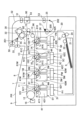
本実施例の画像形成装置の概略構成について説明する。本実施例の画像形成装置は、電子写真方式を用いてシート状の記録材Sにフルカラー画像を形成することが可能な、中間転写方式を採用したタンデム型のカラーレーザプリンタである。図1は、本実施例のプリンタPRの概略断面図である。なお、プリンタPRでは、記録材Sとして主に紙が用いられるため、記録材Sのことを紙ということがあるが、記録材Sは紙に限定されるものではない。記録材Sとしては、例えば、合成樹脂を主体とする材料で構成された合成紙やフィルム、金属層を有する蒸着紙などの特殊紙などの、紙以外の材料又は紙以外の材料を含む材料で構成されたものを用いることもできる。
[Example 1]
<Explanation of image forming apparatus: FIG. 1>
The schematic configuration of the image forming apparatus of this embodiment will be described. The image forming apparatus of this embodiment is a tandem type color laser printer that employs an intermediate transfer method and is capable of forming a full-color image on a sheet-shaped recording material S using an electrophotographic method. FIG. 1 is a schematic cross-sectional view of the printer PR of this embodiment. In the printer PR, paper is mainly used as the recording material S, so the recording material S is sometimes called paper, but the recording material S is not limited to paper. As the recording material S, for example, synthetic paper or film made of a material mainly composed of synthetic resin, special paper such as metal-deposited paper having a metal layer, or materials made of materials other than paper or materials containing materials other than paper can also be used.
プリンタPRは、複数の画像形成部として、それぞれイエロー(Y)、マゼンダ(M)、シアン(C)、ブラック(K)の各色のトナー像を形成する4つの画像形成部PY、PM、PC、PKを有する。これらの画像形成部PY、PM、PC、PKは、後述する中間転写ベルト11の略水平に配置される画像転写面の移動方向に沿って並んで配置されている。プリンタPRは、各画像形成部PY、PM、PC、PKにより形成される4色のトナー像を重ね合わせることでカラー画像を出力できるように構成されている。なお、各色用に設けられた同一又は対応する機能あるいは構成を有する要素については、いずれかの色用の要素であることを示す符号の末尾のY、M、C、Kを省略して総括的に説明することがある。
The printer PR has four image forming units PY, PM, PC, and PK that form toner images of the colors yellow (Y), magenta (M), cyan (C), and black (K) as multiple image forming units. These image forming units PY, PM, PC, and PK are arranged in a line along the direction of movement of the image transfer surface of the
本実施例では、画像形成部Pは、後述する感光ドラム1、帯電ローラ2、露光装置3、現像装置4、クリーニング装置6などを有して構成されている。また、本実施例では、各画像形成部Pにおいて、感光ドラム1と、感光ドラム1に作用するプロセス手段としての帯電ローラ2、現像装置4及びクリーニング装置6とは、一体的に装置本体9に対して着脱可能なプロセスカートリッジ5を構成している。そして、プロセスカートリッジ5の下方に、露光装置(レーザユニット)3が配置されている。本実施例では、プリンタPRの装置本体9とは、プリンタPRの各プロセスカートリッジ5Y、5M、5C、5Kを除いた部分である。
In this embodiment, the image forming section P is configured to include a
像担持体としての回転可能なドラム型の電子写真感光体(感光体)である感光ドラム1は、駆動手段としてのドラム駆動モータ(図示せず)から駆動力が伝達されることで、図中矢印R1方向(時計回り方向)に回転駆動される。回転する感光ドラム1の表面は、帯電手段としてのローラ型の帯電部材である帯電ローラ2によって、所定の極性(本実施例では負極性)の所定の電位に一様に帯電処理される。帯電処理時に、帯電ローラ2には、帯電電圧印加手段としての帯電電源(図示せず)によって、感光ドラム1の帯電極性と同極性(本実施例では負極性)の所定の帯電電圧(帯電バイアス)が印加される。帯電処理された感光ドラム1の表面は、露光手段としての露光装置3によって画像信号に基づいて走査露光され、感光ドラム1上に静電潜像(静電像)が形成される。感光ドラム1上に形成された静電潜像は、現像手段としての現像装置4によって現像剤としてのトナーが供給されて現像(可視化)され、感光ドラム1上にトナー像(トナー画像、現像剤像)が形成される。現像装置4は、現像剤担持体(現像部材)としての現像ローラ41と、トナーを収容する現像容器42と、を有する。現像ローラ41は、駆動手段としてのドラム駆動モータ(図示せず)から駆動力が伝達されることで回転駆動される。現像ローラ41は、現像容器42内のトナーを担持して感光ドラム1との対向部(当接部)である現像部へと搬送し、感光ドラム1上の静電潜像に応じてトナーを感光ドラム1上に付着させる。現像時に、現像ローラ41には、現像電圧印加手段としての現像電源(図示せず)によって、感光ドラム1の帯電極性と同極性(本実施例では負極性)の所定の現像電圧(現像バイアス)が印加される。本実施例では、一様に帯電処理された後に露光されることで電位の絶対値が低下した感光ドラム1上の露光部(イメージ部)に、感光ドラム1の帯電極性(本実施例では負極性)と同極性に帯電したトナーが付着する(反転現像方式)。本実施例では、現像時のトナーの主要な帯電極性であるトナーの正規の帯電極性は負極性である。
The
4つの感光ドラム1Y、1M、1C、1Kに対向するように、中間転写ユニット7が配置されている。中間転写ユニット7は、中間転写ベルト11、3つの張架ローラ12、13、14、4つの1次転写ローラ10Y、10M、10C、10Kなどを有して構成されている。中間転写体としての回転可能な無端状のベルトで構成された中間転写ベルト11は、4つの感光ドラム1Y、1M、1C、1Kに対向するように配置されている。中間転写ベルト11は、複数の張架ローラとしてのテンションローラ12、駆動ローラ13及び2次転写対向ローラ14に掛け渡されて所定の張力で張架されている。駆動ローラ13は、駆動手段としてのベルト駆動モータ(図示せず)から駆動力が伝達されることで回転駆動される。中間転写ベルト11は、駆動ローラ13から駆動力が伝達されることで、図中矢印R2方向(反時計回り方向)に回転(周回移動)する。中間転写ベルト11の内周面側には、各感光ドラム1Y、1M、1C、1Kに対応して、1次転写手段としてのローラ型の1次転写部材である1次転写ローラ10が配置されている。1次転写ローラ10は、感光ドラム1に向けて押圧され、中間転写ベルト11を介して感光ドラム1に当接して、感光ドラム1と中間転写ベルト11との接触部である1次転写部(1次転写ニップ部)N1を形成する。感光ドラム1上に形成されたトナー像は、1次転写部N1において、1次転写ローラ10の作用によって、回転している中間転写ベルト11上に転写(1次転写)される。1次転写時に、1次転写ローラ10には、1次転写電圧印加手段としての1次転写電源(図示せず)によって、トナーの正規の帯電極性とは逆極性(本実施例では正極性)の所定の1次転写電圧(1次転写バイアス)が印加される。例えば、フルカラー画像の形成時には、各感光ドラム1上に形成されたイエロー、マゼンタ、シアン、ブラックの各色のトナー像が、中間転写ベルト11上に重ね合わせられるようにして順次転写される。これにより、4色のトナー像が中間転写ベルト11上に重なった状態で後述する2次転写部N2まで搬送される。
The
中間転写ベルト11の外周面側において、2次転写対向ローラ(2次転写内ローラ)14に対向する位置には、2次転写手段としてのローラ型の2次転写部材である2次転写ローラ(2次転写外ローラ)15が配置されている。2次転写ローラ15は、2次転写対向ローラ14に向けて押圧され、中間転写ベルト11を介して2次転写対向ローラ14に当接して、中間転写ベルト11と2次転写ローラ15との接触部である2次転写部(2次転写ニップ部)N2を形成する。中間転写ベルト11上に形成されたトナー像は、2次転写部N2において、2次転写ローラ15の作用によって、中間転写ベルト11と2次転写ローラ15とに挟持されて搬送されている記録材S上に転写(2次転写)される。2次転写時に、2次転写ローラ15には、2次転写電圧印加手段としての2次転写電源(図示せず)によって、トナーの正規の帯電極性とは逆極性(本実施例では正極性)の所定の2次転写電圧(2次転写バイアス)が印加される。記録用紙などの記録材(転写材、記録媒体、シート)Sは、給紙部20から2次転写部N2へと搬送されてくる。給紙部20は、記録材収納部としての給紙カセット21と、給紙部材としての給紙ローラ22と、搬送部材としての搬送ローラ23と、分離搬送部材としての分離ローラ24と、を有する。給紙カセット21内に収納された記録材Sは、給紙ローラ22によって給紙カセット21から送り出される。給紙ローラ22によって給紙された記録材Sは、搬送ローラ23及び分離ローラ24によって1枚ずつ分離搬送される。そして、給紙部20から搬送された記録材Sは、同期搬送部材としてのレジストローラ対25によって、中間転写ベルト11上のトナー像とタイミングが合わせられて2次転写部N2へと搬送される。
On the outer peripheral surface side of the
トナー像が転写された記録材Sは、定着手段としての定着装置30へと搬送される。定着装置30は、熱源が内周面側に設けられた定着回転体としての定着フィルム31と、加圧回転体としての加圧ローラ32と、を有する。未定着のトナー像を担持した記録材Sは、定着フィルム31と加圧ローラ32とに挟持されて搬送される過程で加熱及び加圧されて、その表面にトナー像が定着(溶融、固着)される。片面プリントの場合、トナー像が定着された記録材Sは、排出部材としての排出ローラ対33によって、装置本体9の外部(機外)に排出(出力)され、装置本体9の上面に設けられた排出部としてのトレイ8上に積載される。
The recording material S onto which the toner image has been transferred is transported to the fixing
また、1次転写後に感光ドラム1上に残留したトナー(1次転写残トナー)は、クリーニング手段としてのクリーニング装置6によって感光ドラム1上から除去されて回収される。クリーニング装置6は、クリーニング部材としてのクリーニングブレード61と、トナーを収容する廃トナー容器62と、を有する。クリーニング装置6は、クリーニングブレード61によって、回転する感光ドラム1の表面から1次転写残トナーを掻き取って、廃トナー容器62内に回収する。また、2次転写後に中間転写ベルト11上に残留したトナー(2次転写残トナー)などの付着物は、中間転写体クリーニング手段としてのベルトクリーニング装置16によって中間転写ベルト11上から除去されて回収される。
Furthermore, the toner remaining on the
なお、レジストローラ対25から2次転写部N2への記録材Sの搬送路に、記録材検知手段としての搬送路センサ27が配置されている。搬送路センサ27は、早着や遅延などの搬送異常に起因するジャムの発生を判断するためのセンサである。プリンタPRは、ジャムが発生したと判断した場合、プリンタPRに設けられた操作表示部PR02(図2)にジャムが発生した旨を表示する。また、プリンタPRは、必要に応じてジャムを解消するための手段に関する情報を操作表示部PR02に表示する。
A
また、プリンタPRは、両面プリント(自動両面プリント)を行うことができるように構成されている。両面プリントの場合、定着装置30を通過した第1面(1面目)に画像が形成された記録材Sは、機外に排出されず、その第2面(2面目)に対する画像形成が行われる。つまり、定着装置30を通過した第1面に画像が形成された記録材Sは、反転ポイント201に向かう方向に搬送される。両面フラッパ55は、記録材Sの搬送方向を排出方向と反転部方向とに切り替えることが可能である。両面プリントを行う場合は、第1面に画像形成済みの記録材Sの搬送方向の先端が両面フラッパ55に到着する前に、両面フラッパ55が記録材Sの搬送方向を反転部方向に切り替える。記録材Sは、反転ポイント201を通過した後、反転ローラ対50によって機外に排出される方向に搬送される。この記録材Sの搬送方向の後端が反転ポイント201を通過し、反転ローラ対50の位置にこの記録材Sが存在する間に、反転ローラ対50が一旦停止する。そして、反転ローラ対50がそれまでとは逆回転方向に回転することにより、この記録材Sは両面搬送路52に向かう方向に搬送される。この記録材Sは、両面搬送路52内で、両面搬送ローラ対51及び再給紙ローラ対53によって、再給紙待機ポイント202、合流ポイント200へと順次搬送される。反転ローラ対50、両面搬送ローラ対51及び再給紙ローラ対53は、駆動手段としての両面搬送モータ92(図2)から駆動力が伝達されて回転する。両面搬送路52は、合流ポイント200において、搬送ローラ23とレジストローラ対25との間の記録材Sの搬送路に合流する。両面搬送路52を通過して表裏を反転された記録材Sは、レジストローラ対25によって2次転写部N2へと搬送される。そして、この記録材Sの第2面に中間転写ベルト11上のトナー像が転写される。記録材Sの第2面に転写されたトナー像は、定着装置30によって記録材S上に定着される。また、両面フラッパ55が記録材Sの搬送方向を排出方向に切り替えることにより、両面に画像が形成された記録材Sは機外に排出される。
The printer PR is also configured to perform double-sided printing (automatic double-sided printing). In the case of double-sided printing, the recording material S on which an image is formed on the first side (first surface) that has passed through the fixing
また、本実施例では、両面搬送路52に検知手段としての画像読み取り部90が設置されている。画像読み取り部90は、画像読み取り手段としてのCIS(Contact Image Sensor:コンタクトイメージセンサ)93、発光素子(図示せず)などを有して構成されている。画像読み取り部90は、両面搬送路52内を搬送される記録材Sやその記録材S上の画像の読み取りを所定のタイミングで開始する。画像読み取り部90は、読み取った画像を、時系列のデジタル画素信号に変換して、メモリ(図示せず)にスキャン画像データとして蓄積する。
In this embodiment, an
<ハードウェア構成の説明:図2>
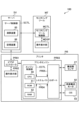
図2は、本実施例における画像形成システム100のハードウェア構成を説明するための模式図である。本実施例では、画像形成システム100は、プリンタPRと、サーバSVと、モニタリングツールMTと、を有する。
<Hardware configuration explanation: Figure 2>
2 is a schematic diagram for explaining the hardware configuration of the
プリンタPRは、ビデオコントローラPR01と、操作表示部PR02と、プリンタエンジンPR03と、を有する。ここで、プリンタPRが有する操作表示部PR02は、図示しないオペレーションパネルや操作ボタンなどを有して構成されている。オペレーションパネルは、情報を表示する表示部及び情報を入力する入力部の機能を有するものであってよい。操作ボタンは、情報を入力する入力部として機能する。ビデオコントローラPR01は、図示しないパーソナルコンピュータなどのホストコンピュータ(外部装置)から送信されたプリントデータ(画像情報)やプリント指示をプリンタエンジンPR03に送信する。プリンタエンジンPR03は、演算処理部としてのCPU80、記憶部としてのROM81及びRAM82を備えたエンジン制御部ECTLと、システムバスPR04と、IOポートPR05と、を有する。また、記録材Sに画像を形成する前述のプロセスを実行するための各装置、例えば、各画像形成部P、中間転写ユニット7、2次転写ローラ15、定着装置30、各種駆動部、各種電源は、プリンタエンジンPR03を構成する。CPU80は、ROM81に記憶されているプログラム及び各種データをRAM82にロードし、RAM82を作業領域とすることでプログラムを実行する。エンジン制御部ECTLは、双方向にアクセス可能なシステムバスPR04を介して、IOポートPR05と接続されている。これにより、エンジン制御部ECTLとIOポートPR05とは、双方向にアクセス可能である。IOポートPR05には、搬送路センサ27、両面搬送モータ92及びCIS93などのプリンタPRの各装置が接続されている。CPU80は、IOポートPR05を介してプリンタPRの各装置を制御する。これにより、エンジン制御部ECTLは、プリンタPRに画像形成などの種々の動作を実行させる。なお、図2では、IOポートPR05を介してエンジン制御部ECTLに接続される装置の例として、本実施例との関係で特に注目する搬送路センサ27、両面搬送モータ92及びCIS93が示されている。ただし、IOポートPR05を介してエンジン制御部ECTLに接続される装置はこれらに限定されるものではない。
The printer PR has a video controller PR01, an operation display unit PR02, and a printer engine PR03. Here, the operation display unit PR02 of the printer PR is configured with an operation panel and operation buttons, not shown. The operation panel may have the functions of a display unit that displays information and an input unit that inputs information. The operation buttons function as an input unit that inputs information. The video controller PR01 transmits print data (image information) and print instructions sent from a host computer (external device) such as a personal computer, not shown, to the printer engine PR03. The printer engine PR03 has an engine control unit ECTL equipped with a
サーバSVは、演算装置85及び記憶装置86を備えたサーバ制御部SCTLを有する。サーバSVは、プリンタPR及びモニタリングツールMTのそれぞれと、双方向にアクセス可能なネットワークで接続されている。これにより、サーバSVと、プリンタPR及びモニタリングツールMTのそれぞれとは、双方向にアクセス可能である。演算装置85は、記憶装置86に保存されたプログラムの実行や、各種データの読み書きを行う。演算装置85にはCPU、GPUなどを、また記憶装置86にはRAM、HDD、SSDなどを直接割り当ててもよいし、仮想マシンなどの仮想環境を割り当ててもよい。サーバSVのサーバ制御部SCTLは、プリンタPRのビデオコントローラPR01を経由することで、プリンタPRのエンジン制御部ECTLとの間での情報の受け渡しを行うことが可能である。また、サーバSVのサーバ制御部SCTLは、インターネットなどのネットワークを通じて、モニタリングツールMTのモニタリングツール制御部MCTLとの間での情報の受け渡しを行うことが可能である。
The server SV has a server control unit SCTL equipped with a
モニタリングツールMTは、サーバ制御部SCTLからの情報を受信するためのモニタリングツール制御部MCTLと、受信した情報を表示するための操作表示部MDSPと、を有する。モニタリングツールMTは、例えば、パーソナルコンピュータで構成される。ここで、モニタリングツールMTが有する操作表示部MDSPは、図示しないディスプレイ、キーボード、マウスなどを有して構成されている。具体的には、モニタリングツールMTの機能は、例えば、パーソナルコンピュータにインストールされたソフトウェアをパーソナルコンピュータが実行することで実現される。なお、モニタリングツールMTの形態は、パーソナルコンピュータやサーバに限らず、仮想マシンなどの仮想環境や、タブレット端末、専用デバイスであってもよい。これらは、それぞれ情報処理装置の例であるといえる。 The monitoring tool MT has a monitoring tool control unit MCTL for receiving information from the server control unit SCTL, and an operation display unit MDSP for displaying the received information. The monitoring tool MT is, for example, configured as a personal computer. Here, the operation display unit MDSP of the monitoring tool MT is configured with a display, keyboard, mouse, etc., which are not shown. Specifically, the functions of the monitoring tool MT are realized, for example, by the personal computer executing software installed on the personal computer. Note that the form of the monitoring tool MT is not limited to a personal computer or a server, and may also be a virtual environment such as a virtual machine, a tablet terminal, or a dedicated device. Each of these can be considered as an example of an information processing device.
<画像情報分析処理の説明:図3、表1>
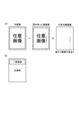
本実施例では、エンジン制御部ECTL及びサーバ制御部SCTLにおいて、記録材Sに本来の画像ではないスジ状のトナー像が形成されてしまう「縦スジ」と呼ばれる画像不良を検知する。具体的な検知アルゴリズムについて図3(a)を用いて説明する。図3(a)は、本実施例における縦スジの検知アルゴリズムを説明するための模式図である。
<Explanation of image information analysis process: Figure 3, Table 1>
In this embodiment, the engine control unit ECTL and the server control unit SCTL detect an image defect called a "vertical streak" in which a streak-like toner image that is not an original image is formed on the recording material S. A specific detection algorithm will be described with reference to Fig. 3A. Fig. 3A is a schematic diagram for explaining the detection algorithm of the vertical streak in this embodiment.
まず、記録材Sに形成したい元画像情報と、画像読み取り部90で読み取った実画像情報と、を取得する。元画像情報は、例えばエンジン制御部ECTLのメモリ(RAM82など)から取得することができ、実画像情報は、例えば画像読み取り部90のメモリ(図示せず)から取得することができる。そして、2つの画像の位置合わせを行うために、2つの画像の差分が最も小さくなる位置を求める。画像の位置合わせは、例えば公知の方法などの任意の方法を用いて行うことができる。位置合わせを行った後、実画像と元画像との差分を取ることで得られた画像を分析対象画像とする。次に、分析対象画像に対して縦方向のエッジを強調するフィルタ、例えばSobelフィルタを適用し、エッジ強調後の画像データに対して縦方向の画像濃度のバラつきを「特徴量」とする。縦方向の画像濃度のバラつきは、例えば斯界にて周知の偏差を求める方法などの任意の方法を用いて求めることができる。そして、例えば、予め決められた閾値以上の特徴量がある場合に画像不良ありと判断することができる。ここで、縦方向は、記録材Sの搬送方向(感光ドラム1の表面の移動方向、副走査方向)と略平行な方向であり、横方向は、感光ドラム1の回転軸線方向(主走査方向)と略平行な方向である。また、画像濃度は、0~255の256段階の濃度レベルで表される。
First, the original image information to be formed on the recording material S and the actual image information read by the
本実施例では、縦スジは、定着装置30の汚れ(例えば、定着フィルム31の表面へのトナーの固着)を起因とするものを想定している。 In this embodiment, it is assumed that the vertical streaks are caused by dirt on the fixing device 30 (e.g., toner adhering to the surface of the fixing film 31).
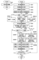
なお、本実施例では、上記アルゴリズムによる縦スジの検知を、表1に示すいくつかの検知形態で行う。「タイプ1」は、エンジン制御部ECTLで算出した特徴量をサーバ制御部SCTLに送信するため、送信するデータ量やサーバ制御部SCTLで実行する計算量が小さいが、分析精度は低い。一方、「タイプ2」及び「タイプ3」は、エンジン制御部ECTLで検知した画像データをサーバ制御部SCTLに送信し、サーバ制御部SCTLで特徴量を算出するため、送信するデータ量やサーバ制御部SCTLで実行する計算量が大きくなるが、分析精度を高めることができる。タイプ2については、エンジン制御部ECTLとサーバ制御部SCTLとの両方で特徴量の算出を行う。つまり、画像の全領域の特徴量をエンジン制御部ECTLで算出して、その特徴量をサーバ制御部SCTLに送信すると共に、画像の一部領域の画像データをサーバ制御部SCTLに送信して、サーバ制御部SCTLでその一部領域の特徴量を算出する。このように、タイプ2では、画像の一部領域の詳細な分析をサーバ制御部SCTLで行うことで、タイプ1における分析精度の低さを補っている。図3(b)は、特徴量の算出を行う画像領域を説明するための模式図である。表1に示す「画像領域」は、図3(b)に示すような特徴量の算出を行う画像領域を示し、画像の全領域を用いた分析の方が、画像の一部領域を用いた分析よりも、分析精度の向上につながる。また、表1に示す「分解能」は、上述の画像処理を施す単位を示し、値が小さい場合の方が、値が大きい場合よりも、分析精度の向上につながる。画像の一部領域は、所望の分析精度などに応じて適宜選択することができるが、図3(b)に示す例では、縦方向における画像の1/4程度の領域である。
In this embodiment, the detection of vertical streaks using the above algorithm is performed in several detection forms shown in Table 1. In "
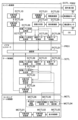
<機能ブロックの説明:図4、図5、表2~表7>
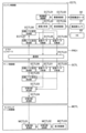
本実施例におけるエンジン制御部ECTL、ビデオコントローラPR01、サーバ制御部SCTL及びモニタリングツール制御部MCTLの機能について図4を用いて説明する。図4は、エンジン制御部ECTL、ビデオコントローラPR01、サーバ制御部SCTL及びモニタリングツール制御部MCTLの機能ブロックを示す模式図である。
<Explanation of functional blocks: Fig. 4, Fig. 5, Tables 2 to 7>
The functions of the engine control unit ECTL, the video controller PR01, the server control unit SCTL, and the monitoring tool control unit MCTL in this embodiment will be described with reference to Fig. 4. Fig. 4 is a schematic diagram showing the functional blocks of the engine control unit ECTL, the video controller PR01, the server control unit SCTL, and the monitoring tool control unit MCTL.
エンジン制御部ECTLの機能は、例えば、CPU80がROM81に記憶されているプログラムやRAM82に記憶されているデータに基づいて処理を実行することで実現される。ビデオコントローラPR01の機能は、例えば、ビデオコントローラPR01において演算処理部としてのCPU(図示せず)が記憶部としてのROMやRAM(図示せず)に記憶されたプログラムやデータに基づいて処理を実行することで実現される。サーバ制御部SCTLの機能は、例えば、演算装置85が記憶装置86に記憶されているプログラムやデータに基づいて処理を実行することで実現される。また、モニタリングツール制御部MCTLの機能は、例えば、モニタリングツールMTにおいて演算処理部としてのCPU(図示せず)が記憶部としてのROMやRAM(図示せず)に記憶されたプログラムやデータに基づいて処理を実行することで実現される。ただし、これらの機能の全部又は一部がASIC(特定用途集積回路)やFPGA(フィールドプログラマブルアレイ)などのハードウェア回路により実現されてもよい。
The function of the engine control unit ECTL is realized, for example, by the
エンジン制御部ECTLは、両面搬送制御を行う機能、画像情報を分析する機能、動作履歴に関する基礎データを収集する機能、動作履歴に関する拡張データを収集する機能、及び収集レベルを管理する機能を有する。 The engine control unit ECTL has the functions of controlling double-sided transport, analyzing image information, collecting basic data related to the operation history, collecting extended data related to the operation history, and managing the collection level.
サーバ制御部SCTLは、基礎データから画像不良を分析する機能、拡張データから画像不良を分析する機能、対策内容を決定する機能、対策内容を送信する機能、収集レベルを決定する機能、及び収集レベルを送信する機能を有する。 The server control unit SCTL has the functions of analyzing image defects from basic data, analyzing image defects from extended data, determining the content of countermeasures, transmitting the content of countermeasures, determining the collection level, and transmitting the collection level.
モニタリングツール制御部MCTLは、対策内容を表示する機能を有する。 The monitoring tool control unit MCTL has the function of displaying the details of the measures.
次に、それぞれの機能について順に説明する。 Next, we'll explain each function in turn.
・両面搬送制御を行う機能
エンジン制御部ECTLは、両面搬送制御を行う機能ブロックとして、両面搬送制御手段としての両面搬送制御部ECTL01と、駆動制御手段としての駆動制御部ECTL02と、を有する。両面搬送制御部ECTL01は、次の順序で両面搬送制御を行う。図5は、両面搬送制御を説明するための、プリンタPRにおける両面搬送路52の付近の概略断面図である。
1.両面フラッパ55を制御して、第1面に画像が形成された1枚目の記録材S1を、反転ポイント201に向かう方向に搬送する。(図5(a))
2.駆動制御部ECTL02に両面搬送モータ92の駆動を指示し、1枚目の記録材S1を、両面搬送路52を通して、再給紙待機ポイント202に向かう方向に搬送する。また、2枚目の記録材S2を、第1面に画像形成するために2次転写部N2へと搬送する。(図5(b))
3.駆動制御部ECTL02に両面搬送モータ92の駆動を指示し、1枚目の記録材S1を再給紙待機ポイント202で待機させる。その間に、第1面に画像が形成された2枚目の記録材S2を、反転ポイント201に向かう方向に搬送する。(図5(c))
4.駆動制御部ECTL02に両面搬送モータ92の駆動を指示し、1枚目の記録材S1を、再給紙ローラ対53によりレジストローラ対25へと再給紙し、第2面に対する画像の形成(2次転写)を開始する。(図5(d))
5.両面フラッパ55を制御して、第2面に画像が形成された1枚目の記録材S1を、排紙ローラ対33に向かう方向に搬送し、機外へ排出する。また、駆動制御部ECTL02に両面搬送モータ92の駆動を指示し、2枚目の記録材S2を、両面搬送路52を通して、合流ポイント200に向かう方向に搬送する。そして、第2面に画像を形成するために2枚目の記録材S2を2次転写部N2へと搬送する。その後、3枚目の記録材S3を、第1面に画像を形成するために2次転写部N2へと搬送する(図5(e))。
The engine control unit ECTL has a duplex conveying control unit ECTL01 as a duplex conveying control means and a drive control unit ECTL02 as a drive control means as a functional block that performs duplex conveying control. The duplex conveying control unit ECTL01 performs duplex conveying control in the following order. Figure 5 is a schematic cross-sectional view of the vicinity of the
1. The double-
2. The drive control unit ECTL02 is instructed to drive the double-sided conveying
3. The drive control unit ECTL02 is instructed to drive the double-sided conveying
4. The drive control unit ECTL02 is instructed to drive the double-sided conveying
5. The double-
・画像情報を分析する機能
エンジン制御部ECTLは、画像情報を分析する機能ブロックとして、画像分析手段としての画像分析部ECTL03と、検知制御手段としての検知制御部ECTL04と、を有する。検知制御部ECTL04は、両面搬送制御部ECTL01による制御によって両面搬送路52を搬送される記録材Sの搬送方向の先端が画像読み取り部90に到達すると、CIS93を用いて画像の読み取りを実行する。そして、検知制御部ECTL04は、スキャン画像データを画像分析部ECTL03に受け渡す。画像分析部ECTL03は、検知制御部ECTL04から受け渡された画像データを画像読み取り日時と関係づけてRAM82に保存すると共に、表1に示したタイプ1の検知形態で特徴量を算出する処理を行い、その結果をRAM82に保存する。特徴量(基礎データ)は、画像形成装置の動作履歴に関するデータ(動作履歴データ)の一例である。以下、スキャン画像データのサイズは、縦(副走査方向)hピクセル×横(主走査方向)wピクセルを前提として説明する。
Function of Analyzing Image Information The engine control unit ECTL has an image analysis unit ECTL03 as an image analysis means and a detection control unit ECTL04 as a detection control means as a functional block for analyzing image information. When the leading edge of the recording material S in the conveying direction conveyed through the double-sided conveying
・基礎データを収集する機能
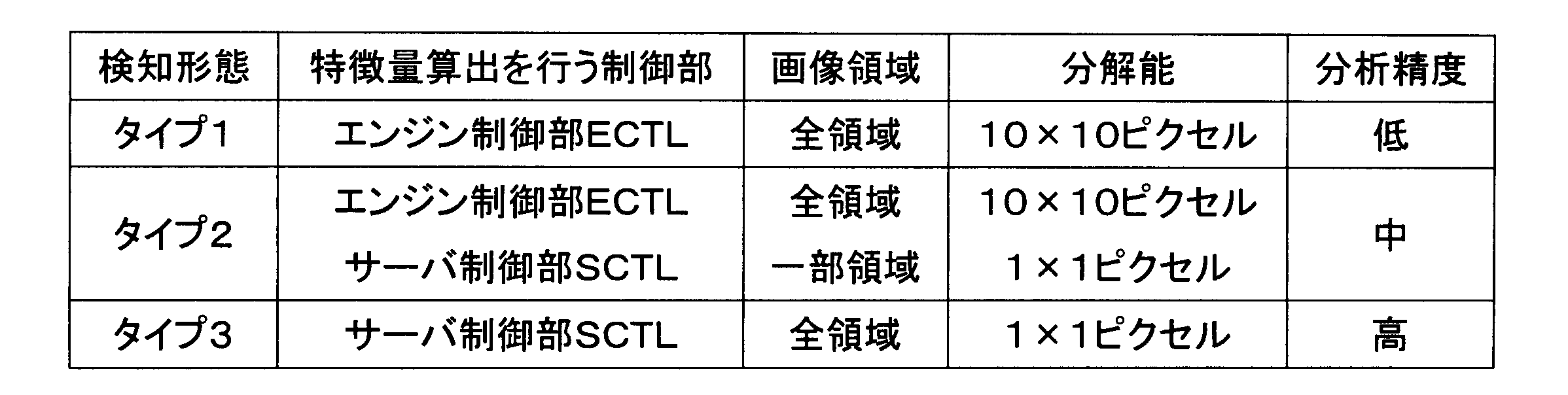
エンジン制御部ECTLは、基礎データを収集する機能ブロックとして、基礎データ収集手段としての基礎データ収集部ECTL05を有する。基礎データ収集部ECTL05は、画像分析部ECTL03が保存した特徴量(基礎データ)を、ビデオコントローラPR01が有する通信手段としての通信部PCTL01に伝達する。ただし、伝達の可否設定は、後述する収集レベル設定反映部ECTL08が行い、伝達が「無効」と指定された場合は、基礎データの伝達処理を行わない。また、通信部PCTL01は、基礎データ収集部ECTL05から特徴量が伝達されると、画像読み取り日時及び特徴量をサーバ制御部SCTLに通知する。サーバ制御部SCTLは、受信した画像読み取り日時及び特徴量を記憶装置86に保存する。基礎データ収集部ECTL05は、ビデオコントローラPR01が有する通信部PCTL01を経由して、後述するサーバ制御部SCTLの基礎データ分析部SCTL01に直接的に画像読み取り日時及び特徴量を伝達してもよい。なお、保存された基礎データの例を表2に示す。表2に示す「n」は、w÷10(表1に示す分解能10ピクセルに相当する)の整数部分である。
Function of collecting basic data The engine control unit ECTL has a basic data collection unit ECTL05 as a basic data collection means as a functional block for collecting basic data. The basic data collection unit ECTL05 transmits the feature amount (basic data) stored by the image analysis unit ECTL03 to a communication unit PCTL01 as a communication means of the video controller PR01. However, the setting of whether or not to transmit is performed by a collection level setting reflection unit ECTL08 described later, and if the transmission is specified as "disabled", the transmission process of the basic data is not performed. In addition, when the feature amount is transmitted from the basic data collection unit ECTL05, the communication unit PCTL01 notifies the server control unit SCTL of the image reading date and time and the feature amount. The server control unit SCTL stores the received image reading date and time and the feature amount in the
・拡張データを収集する機能
エンジン制御部ECTLは、拡張データを収集する機能ブロックとして、拡張データ収集手段としての拡張データ収集部ECTL06を有する。拡張データ収集部ECTL06は、画像分析部ECTL03が保存した画像データから指定された領域の画像データ(拡張データ)を抽出し、ビデオコントローラPR01が有する通信部PCTL01に伝達する。ただし、領域指定は後述する収集レベル設定反映部ECTL08が行い、指定された領域が「0(なし)」の場合は、拡張データの伝達処理を行わない。また、通信部PCTL01は、拡張データ収集部ECTL06から拡張データが伝達されると、画像読み取り日時及び画像データをサーバ制御部SCTLに通知する。指定された領域の画像データ(拡張データ)は、画像形成装置の動作履歴に関するデータ(動作履歴データ)の一例である。サーバ制御部SCTLは、受信した画像読み取り日時及び画像データを記憶装置86に保存する。拡張データ収集部ECTL06は、ビデオコントローラPR01が有する通信部PCTL01を経由して、後述するサーバ制御部SCTLの拡張データ分析部SCTL02に直接的に画像読み取り日時及び画像データを伝達してもよい。なお、保存された拡張データの例を表3に示す。
Function of collecting extended data The engine control unit ECTL has an extended data collection unit ECTL06 as an extended data collection means, which is a functional block for collecting extended data. The extended data collection unit ECTL06 extracts image data (extended data) of a specified area from the image data stored by the image analysis unit ECTL03, and transmits it to the communication unit PCTL01 of the video controller PR01. However, the area is specified by the collection level setting reflection unit ECTL08 described later, and if the specified area is "0 (none)", the transmission process of the extended data is not performed. In addition, when the extended data is transmitted from the extended data collection unit ECTL06, the communication unit PCTL01 notifies the server control unit SCTL of the image reading date and time and the image data. The image data (extended data) of the specified area is an example of data (operation history data) related to the operation history of the image forming apparatus. The server control unit SCTL stores the received image reading date and time and image data in the

・収集レベルを管理する機能
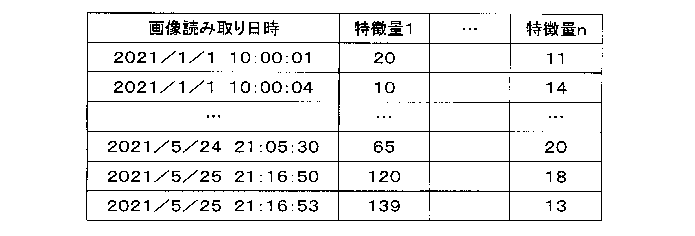
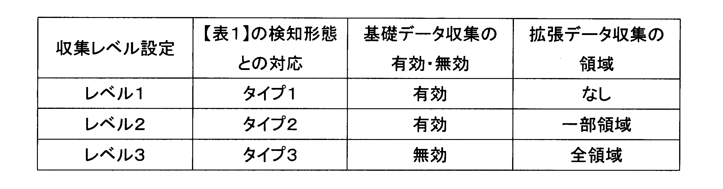
エンジン制御部ECTLは、動作履歴データの収集レベルを管理する機能ブロックとして、収集レベル設定受信手段としての収集レベル設定受信部ECTL07と、収集レベル設定反映手段としての収集レベル設定反映部ECTL08と、を有する。収集レベル設定受信部ECTL07は、後述するサーバ制御部SCTLが有する収集レベル設定送信部SCTL06から収集レベル設定を受信する。本実施例における収集レベル設定は、基礎データ収集部ECTL05と拡張データ収集部ECTL06とに、基礎データ収集の可否と拡張データ収集の領域とをそれぞれ指示することであり、エンジン制御部ECTLへのコマンドとして表現される。収集レベル設定反映部ECTL08は、収集レベル設定受信部ECTL07が収集レベル設定を指示するコマンドを受信した場合、基礎データの収集レベルと拡張データの収集レベルとを表4に示すように設定(変更)する。収集レベル設定は、「レベル1」が最も分析精度が低く、「レベル2」の分析精度は「レベル1」よりも高く、「レベル3」が最も分析精度が高い。一方、分析精度のより高い収集レベル設定は、より多くのシステムのリソースを使用し、運用コストがかかる傾向がある。
Function of managing collection level The engine control unit ECTL has a collection level setting receiving unit ECTL07 as a collection level setting receiving means and a collection level setting reflecting unit ECTL08 as a collection level setting reflecting means as a functional block for managing the collection level of the operation history data. The collection level setting receiving unit ECTL07 receives the collection level setting from a collection level setting transmitting unit SCTL06 of the server control unit SCTL described later. The collection level setting in this embodiment is to instruct the basic data collection unit ECTL05 and the extended data collection unit ECTL06 on whether to collect basic data and the area of extended data collection, respectively, and is expressed as a command to the engine control unit ECTL. When the collection level setting receiving unit ECTL07 receives a command instructing the collection level setting, the collection level setting reflecting unit ECTL08 sets (changes) the collection level of basic data and the collection level of extended data as shown in Table 4. The collection level settings have the lowest analytical accuracy, with "
・基礎データから画像不良を分析する機能
サーバ制御部SCTLは、基礎データから画像不良を分析する機能ブロックとして、基礎データ分析手段としての基礎データ分析部SCTL01を有する。基礎データ分析部SCTL01は、基礎データ収集部ECTL05から受信した(記憶装置86に保存された)特徴量に対し、直近X枚分の平均Ai(i=1~n)を算出する。本実施例では、X=100とし、データ数がXに満たない場合はAiを未算出とする。また、基礎データ分析部SCTL01は、Vi=max(Ai)-min(Ai)を計算し、Vmax=max(Vi)に対して、表5に示す基準に基づいて縦スジによる画像不良の分析を行い、分析結果を画像読み取り日時に紐づけて記憶装置86に保存する。
Function of Analyzing Image Defects from Basic Data The server control unit SCTL has a basic data analysis unit SCTL01 as a basic data analysis means, which is a functional block for analyzing image defects from basic data. The basic data analysis unit SCTL01 calculates the average Ai (i = 1 to n) of the most recent X sheets for the feature amount received from the basic data collection unit ECTL05 (stored in the storage device 86). In this embodiment, X = 100, and if the number of data does not reach X, Ai is not calculated. In addition, the basic data analysis unit SCTL01 calculates Vi = max (Ai) - min (Ai), and analyzes image defects due to vertical streaks for Vmax = max (Vi) based on the criteria shown in Table 5, and stores the analysis result in the

・拡張データから画像不良を分析する機能
サーバ制御部SCTLは、拡張データから画像不良を分析する機能ブロックとして、拡張データ分析手段としての拡張データ分析部SCTL02を有する。拡張データ分析部SCTL02は、拡張データ収集部ECTL06から受信した(記憶装置86に保存された)画像データからピクセル毎に特徴量を算出し、直近X枚分の平均Aj(j=1~w)を算出する。本実施例では、X=100とし、データ数がXに満たない場合はAjを未算出とする。また、拡張データ分析部SCTL02は、Wj=max(Aj)-min(Aj)を計算し、Wmax=max(Vj)に対して、表5に示す基準に基づいて縦スジによる画像不良の分析を行い、分析結果を画像読み取り日時に紐づけて記憶装置86に保存する。
Function of Analyzing Image Defects from Extended Data The server control unit SCTL has an extended data analysis unit SCTL02 as an extended data analysis means, which is a functional block for analyzing image defects from extended data. The extended data analysis unit SCTL02 calculates feature amounts for each pixel from image data received from the extended data collection unit ECTL06 (stored in the storage device 86), and calculates the average Aj (j = 1 to w) of the most recent X sheets. In this embodiment, X = 100, and if the number of data does not reach X, Aj is left uncalculated. In addition, the extended data analysis unit SCTL02 calculates Wj = max (Aj) - min (Aj), and analyzes image defects due to vertical streaks for Wmax = max (Vj) based on the criteria shown in Table 5, and stores the analysis results in the
・対策内容を決定する機能
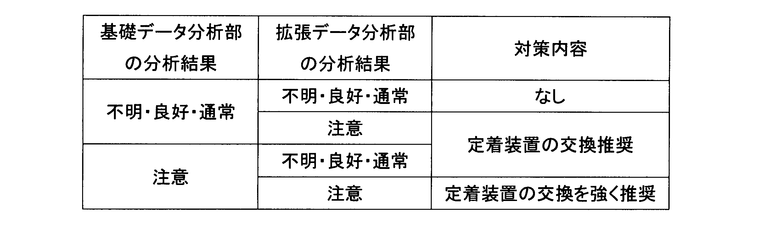
サーバ制御部SCTLは、対策内容を決定する機能ブロックとして、対策内容決定手段としての対策内容決定部SCTL03を有する。対策内容決定部SCTL03は、基礎データ分析部SCTL01及び拡張データ分析部SCTL02の分析結果に基づいて、対策内容を決定する。本実施例では、画像不良の発生しているユニットの例を定着装置30としており、対策内容決定部SCTL03は、表6に示す基準に従い、対策内容を決定する。対策内容決定部SCTL03は、決定した対策内容をモニタリングツールMTに通知する。表6に示すように、対策内容決定部SCTL03は、基礎データ分析部SCTL01の分析結果と拡張データ分析部SCTL02の分析結果とを統合する。そして、いずれかの分析結果において「注意」と判断された場合には「定着装置の交換推奨」コマンドを通知し、両方の分析結果において「注意」と判断された場合には「定着装置の交換を強く推奨」コマンドを通知する。
Function of determining countermeasure contents The server control unit SCTL has a countermeasure contents determination unit SCTL03 as a countermeasure contents determination means, which is a functional block for determining countermeasure contents. The countermeasure contents determination unit SCTL03 determines countermeasure contents based on the analysis results of the basic data analysis unit SCTL01 and the extended data analysis unit SCTL02. In this embodiment, the fixing
・対策内容を送信する機能
サーバ制御部SCTLは、対策内容を送信する機能ブロックとして、対策内容送信手段(通知手段)としての対策内容送信部SCTL04を有する。対策内容送信部SCTL04は、対策内容決定部SCTL03が決定した対策内容を、ネットワークを経由して、後述するモニタリング制御部MCTLが有する対策内容受信部MCTL01に伝達する。モニタリングツールMTは、サーバ制御部SCTLから受信した対策内容をモニタリングツールMTの記憶部に一旦保存してもよい。本実施例では、上述の対策内容は、通知クライアント装置としてのモニタリングツールMTへのコマンドとして伝達する。
Function of transmitting countermeasure contents The server control unit SCTL has a countermeasure content transmitting unit SCTL04 as a countermeasure content transmitting means (notification means) as a functional block for transmitting countermeasure contents. The countermeasure content transmitting unit SCTL04 transmits the countermeasure contents determined by the countermeasure content determining unit SCTL03 via a network to a countermeasure content receiving unit MCTL01 of the monitoring control unit MCTL, which will be described later. The monitoring tool MT may temporarily store the countermeasure contents received from the server control unit SCTL in the memory unit of the monitoring tool MT. In this embodiment, the above-mentioned countermeasure contents are transmitted as commands to the monitoring tool MT, which is a notification client device.
・対策内容を表示する機能
モニタリングツール制御部MCTLは、対策内容を表示する機能ブロックとして、対策内容受信手段としての対策内容受信部MCTL01と、対策内容反映手段としての対策内容反映部MCTL02と、表示制御手段としての表示制御部MCTL03と、を有する。本実施例では、画像不良の状態、具体的には前述の基礎データ及び拡張データの分析結果に基づいて、モニタリングツールMTの操作表示部MDSPの表示内容を変更する。対策内容受信部MCTL01は、サーバ制御部SCTLが有する対策内容送信部SCTL04から対策内容を受信する(あるいはモニタリングツールMTの記憶部から取得する)。本実施例では、対策内容として、「定着装置の交換推奨」や「定着装置の交換を強く推奨」のようなディーラへの指示をモニタリングツールMTの操作表示部MDSPに表示する。対策内容反映部MCTL02は、対策内容受信部MCTL01が「定着装置の交換推奨」コマンドを受信した場合、対策内容として「定着装置の交換推奨」を示す情報を操作表示部MDSPに表示するように表示制御部MCTL03に指示する。表示制御部MCTL03は、例えば、単に定着装置30の交換が推奨される旨を表示するか、これに加えて又は代えて、交換用の定着装置30の発注などの準備指示を操作表示部MDSPに表示する。また、対策内容反映部MCTL02は、対策内容受信部MCTL01が「定着装置の交換を強く推奨」コマンドを受信した場合、対策内容として「定着装置の交換を強く推奨」を示す情報を操作表示部MDSPに表示するように表示制御部MCTL03に指示する。表示制御部MCTL03は、例えば、単に定着装置30の交換が強く推奨される旨を表示するか、これに加えて又は代えて、サービス出動及び定着装置30の交換の指示を操作表示部MDSPに表示する。これにより、ディーラは、操作表示部MDSPの表示から必要な対策を確認することが可能になる。
Function of displaying countermeasure contents The monitoring tool control unit MCTL has a countermeasure content receiving unit MCTL01 as a countermeasure content receiving means, a countermeasure content reflecting unit MCTL02 as a countermeasure content reflecting means, and a display control unit MCTL03 as a display control means, as functional blocks for displaying countermeasure contents. In this embodiment, the display contents of the operation display unit MDSP of the monitoring tool MT are changed based on the state of the image defect, specifically, the analysis results of the basic data and the extended data described above. The countermeasure content receiving unit MCTL01 receives the countermeasure contents from the countermeasure content transmitting unit SCTL04 of the server control unit SCTL (or obtains them from the memory unit of the monitoring tool MT). In this embodiment, as the countermeasure contents, instructions to the dealer such as "Replacement of the fixing device is recommended" or "Replacement of the fixing device is strongly recommended" are displayed on the operation display unit MDSP of the monitoring tool MT. When the countermeasure content receiving unit MCTL01 receives the "replacement of the fixing device recommended" command, the countermeasure content reflecting unit MCTL02 instructs the display control unit MCTL03 to display information indicating "replacement of the fixing device recommended" as the countermeasure content on the operation display unit MDSP. The display control unit MCTL03, for example, simply displays that replacement of the fixing
・収集レベル設定を決定する機能
サーバ制御部SCTLは、収集レベル設定を決定する機能ブロックとして、収集レベル設定決定手段(収集データ設定手段)としての収集レベル設定決定部SCTL05を有する。収集レベル設定決定部SCTL05は、基礎データ分析部SCTL01及び拡張データ分析部SCTL02の分析結果に基づいて、収集レベル設定を決定する。本実施例では、収集レベル設定決定部SCTL05は、表7に示す基準に従い、収集レベル設定を決定する。表7に示すように、収集レベル設定決定部SCTL05は、基礎データ分析部SCTL01の分析結果と拡張データ分析部SCTL02の分析結果とを統合する。そして、「注意」と判断された数に応じて収集レベル設定を上げる。
Function of Determining Collection Level Setting The server control unit SCTL has a collection level setting determination unit SCTL05 as a collection level setting determination means (collected data setting means) as a functional block that determines the collection level setting. The collection level setting determination unit SCTL05 determines the collection level setting based on the analysis results of the basic data analysis unit SCTL01 and the extended data analysis unit SCTL02. In this embodiment, the collection level setting determination unit SCTL05 determines the collection level setting according to the criteria shown in Table 7. As shown in Table 7, the collection level setting determination unit SCTL05 integrates the analysis results of the basic data analysis unit SCTL01 and the analysis results of the extended data analysis unit SCTL02. Then, the collection level setting is increased according to the number of times determined to be "caution".

・収集レベル設定を送信する機能
サーバ制御部SCTLは、収集レベル設定を送信する機能ブロックとして、収集レベル設定送信手段としての収集レベル設定送信部SCTL06を有する。収集レベル設定送信部SCTL06は、収集レベル設定決定部SCTL05が決定した収集レベル設定を、ビデオコントローラPR01が有する通信部PCTL01を経由して、エンジン制御部ECTLが有する収集レベル設定受信部ECTL07に伝達する。
The server control unit SCTL has a collecting level setting transmission unit SCTL06 as a collecting level setting transmission means, which is a functional block that transmits the collecting level setting. The collecting level setting transmission unit SCTL06 transmits the collecting level setting determined by the collecting level setting determination unit SCTL05 to a collecting level setting receiving unit ECTL07 in the engine control unit ECTL via a communication unit PCTL01 in the video controller PR01.
このように、サーバSVの収集レベル設定決定部SCTL05は、収集レベル設定送信部SCTL06を介して、プリンタPRに、基礎データ及び拡張データの分析結果に基づいて決定した収集レベル設定を通知する。これにより、プリンタPRの基礎データ収集部ECTL05及び拡張データ収集部ECTL06は、収集レベル設定受信部ECTL07及び収集レベル設定反映部ECTL08を介して、データの収集に関する設定である収集レベル設定が変更される。そして、基礎データ収集部ECTL05及び拡張データ収集部ECTL06は、この収集レベル設定に基づいて動作履歴データを収集し、収集した動作履歴データをサーバSVに伝達する。 In this way, the collection level setting determination unit SCTL05 of the server SV notifies the printer PR of the collection level setting determined based on the analysis results of the basic data and extended data via the collection level setting transmission unit SCTL06. As a result, the basic data collection unit ECTL05 and extended data collection unit ECTL06 of the printer PR change the collection level setting, which is a setting related to data collection, via the collection level setting reception unit ECTL07 and collection level setting reflection unit ECTL08. The basic data collection unit ECTL05 and extended data collection unit ECTL06 then collect operation history data based on this collection level setting and transmit the collected operation history data to the server SV.
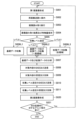
<制御部の動作の説明:図6>
本実施例におけるエンジン制御部ECTL、サーバ制御部SCTL、及びモニタリングツール制御部MCTLの動作について図6を用いて説明する。図6は、本実施例におけるエンジン制御部ECTL、サーバ制御部SCTL、及びモニタリングツール制御部MCTLの動作を説明するためのフローチャートである。
<Explanation of the operation of the control unit: Figure 6>
The operations of the engine control unit ECTL, the server control unit SCTL, and the monitoring tool control unit MCTL in this embodiment will be described with reference to Fig. 6. Fig. 6 is a flowchart for explaining the operations of the engine control unit ECTL, the server control unit SCTL, and the monitoring tool control unit MCTL in this embodiment.
図6のフローチャートの手順は、エンジン制御部ECTL(プリンタエンジンPR03)がプリント指示を受けると開始される。エンジン制御部ECTLは、プリント指示を受けると、記録材Sの第1面に対して前述の画像形成プロセスにより画像を形成するようにプリンタPRの各装置を制御する(S001)。次に、エンジン制御部ECTLは、1枚目の記録材S1を、反転ローラ対50に向かう方向に案内するよう両面フラッパ55に指示し、両面搬送路52へと搬送する(S002)。次に、エンジン制御部ECTLは、記録材S1の搬送方向の先端が画像読み取り部90に到達すると、CIS93を用いて画像読み取りを実行する(S003)。次に、エンジン制御部ECTLは、画像分析部ECTL03において、読み取られた画像データと算出した特徴量をRAM82に保存する(S004)。その後、エンジン制御部ECTLは、基礎データ収集部ECTL05、拡張データ収集部ECTL06において、収集レベル設定に応じて(S005)、特徴量及び画像データのうちの少なくとも一方をサーバ制御部SCTLに通知する(S006L1、S006L2、S006L3)。つまり、収集レベル設定がレベル1の場合は、基礎データ収集部ECTL05が特徴量をサーバ制御部SCTLに通知する(S006L1)。また、収集レベル設定がレベル2の場合は、基礎データ収集部ECTL05が特徴量を、また拡張データ収集部ECTL06が画像データをそれぞれサーバ制御部SCTLに通知する(S006L2)。また、収集レベル設定がレベル3の場合は、拡張データ収集部ECTL06が画像データをサーバ制御部SCTLに通知する(S006L3)。次に、サーバ制御部SCTLは、基礎データ分析部SCTL01、拡張データ分析部SCTL02において、受信した特徴量及び画像データに基づいて、画像不良の分析を行う(S007)。つまり、基礎データ分析部SCTL01は、基礎データ収集部ECTL05から受信した特徴量に基づいて、画像不良の分析を行う。また、拡張データ分析部SCTL02は、拡張データ収集部ECTL06から受信した画像データに基づいて画像不良の分析を行う。
The procedure of the flowchart in FIG. 6 is started when the engine control unit ECTL (printer engine PR03) receives a print instruction. When the engine control unit ECTL receives the print instruction, it controls each device of the printer PR to form an image on the first side of the recording material S by the image formation process described above (S001). Next, the engine control unit ECTL instructs the double-
次に、サーバ制御部SCTLは、対策内容決定部SCTL03において、基礎データ及び拡張データの分析結果に基づいて対策内容を決定し、モニタリングツール制御部MCTLに送信する(S008)。本実施例では、対策内容決定部SCTL03は、表6に示す基準に従って対策内容を決定する。次に、モニタリングツール制御部MCTLは、対策内容受信部MCTL01において、対策内容を受信する。すると、モニタリングツール制御部MCTLは、対策内容反映部MCTL02において、受信した対策内容を表示制御部MCTL03による操作表示部MDSPの制御に反映する(S009)。本実施例では、「定着装置の交換推奨」や「定着装置の交換を強く推奨」のような対策内容を示すコマンドに従って、表示制御部MCTL03がディーラへの指示を操作表示部MDSPに表示する。 Next, the server control unit SCTL determines the countermeasure content based on the analysis results of the basic data and the extended data in the countermeasure content determination unit SCTL03, and transmits it to the monitoring tool control unit MCTL (S008). In this embodiment, the countermeasure content determination unit SCTL03 determines the countermeasure content according to the criteria shown in Table 6. Next, the monitoring tool control unit MCTL receives the countermeasure content in the countermeasure content receiving unit MCTL01. Then, the monitoring tool control unit MCTL reflects the received countermeasure content in the control of the operation display unit MDSP by the display control unit MCTL03 in the countermeasure content reflection unit MCTL02 (S009). In this embodiment, the display control unit MCTL03 displays instructions to the dealer on the operation display unit MDSP according to commands indicating the countermeasure content, such as "Replacement of the fixing device recommended" or "Replacement of the fixing device strongly recommended".
次に、サーバ制御部SCTLは、収集レベル設定決定部SCTL05において、基礎データ及び拡張データの分析結果に基づいて収集レベル設定を決定し、エンジン制御部ECTLに送信する(S010)。本実施例では、収集レベル設定決定部SCTL05は、表7に示す基準に従って収集レベル設定を決定する。次に、エンジン制御部ECTLは、収集レベル設定受信部ECTL07において、収集レベル設定を受信する。すると、エンジン制御部ECTLは、収集レベル設定反映部ECTL08において、受信した収集レベル設定を、基礎データ収集部ECTL05及び拡張データ収集部ECTL06のそれぞれによる制御(基礎データ収集の可否の設定、拡張データ収集の領域の設定)に反映する(S011)。 Next, the server control unit SCTL determines the collection level setting in the collection level setting determination unit SCTL05 based on the analysis results of the basic data and extended data, and transmits it to the engine control unit ECTL (S010). In this embodiment, the collection level setting determination unit SCTL05 determines the collection level setting according to the criteria shown in Table 7. Next, the engine control unit ECTL receives the collection level setting in the collection level setting receiving unit ECTL07. Then, the engine control unit ECTL reflects the received collection level setting in the collection level setting reflection unit ECTL08 to the control (setting of whether basic data is collected, setting of the extended data collection area) by each of the basic data collection unit ECTL05 and the extended data collection unit ECTL06 (S011).
なお、説明の便宜上、S008~S009の手順と、S010~S011の手順と、を直列的に記載しているが、これらの手順は上記とは逆の順番で実行されてもよいし、実質的に同時に実行されてもよい。 For ease of explanation, steps S008 to S009 and steps S010 to S011 are described in series, but these steps may be executed in the reverse order or may be executed substantially simultaneously.
次に、エンジン制御部ECTLは、記録材Sの第2面に対して前述の画像形成プロセスにより画像を形成し、機外へ排出するように、プリンタPRの各装置を制御する(S020)。 Next, the engine control unit ECTL controls each device of the printer PR to form an image on the second side of the recording material S by the image forming process described above and eject the recording material S outside the machine (S020).
その後、エンジン制御部ECTLは、次の記録材Sに対するプリント指示があれば(S021)、再び記録材Sの第1面に対する画像形成に戻り(S001)、そうでなければ制御を終了する。 After that, if there is an instruction to print the next recording material S (S021), the engine control unit ECTL returns to image formation on the first side of the recording material S (S001), otherwise it ends control.
このように、本実施例では、画像形成システム100は、動作履歴データの分析結果に基づいて、収集レベル設定を動的に調整する。具体的には、本実施例では、基礎データ分析部SCTL01の分析結果と拡張データ分析部SCTL02の分析結果とに基づいて、基礎データ収集部ECTL05の基礎データ収集の可否の設定及び拡張データ収集部ECTL06拡張データ収集の領域の設定を動的に調整する。これにより、動作履歴などに応じた求められる分析精度の変更(変化)などに柔軟に対応しながら、運用コストを最適化することができる。
In this manner, in this embodiment, the
[実施例2]
次に、本発明の他の実施例について説明する。本実施例の画像形成システム及び画像形成装置の基本的な構成及び動作は、実施例1の画像形成システム及び画像形成装置のものと同じである。したがって、本実施例の画像形成システム及び画像形成装置において、実施例1のものと同一又は対応する機能あるいは構成を有する要素については、実施例1と同一の符号を付して詳しい説明は省略する。
[Example 2]
Next, another embodiment of the present invention will be described. The basic configuration and operation of the image forming system and image forming apparatus of this embodiment are the same as those of the image forming system and image forming apparatus of
本実施例では、画像形成システム100は、動作履歴データの分析結果と、動作履歴データの収集レベル(収集レベル設定)の調整パターンを指定する情報としての契約プラン情報と、に基づいて、収集レベル設定を決定する。
In this embodiment, the
<機能ブロックの説明:図7>
図7は、本実施例におけるエンジン制御部ECTL、サーバ制御部SCTL及びモニタリングツール制御部MCTLの機能ブロックを示す模式図である。本実施例は、主に、画像形成システム100が契約プラン設定部MCTL04を使用して収集レベル設定を決定する点が実施例1と異なる。
<Explanation of functional blocks: Figure 7>
7 is a schematic diagram showing the functional blocks of the engine control unit ECTL, the server control unit SCTL, and the monitoring tool control unit MCTL in this embodiment. This embodiment is mainly different from the first embodiment in that the
本実施例では、モニタリングツール制御部MCTLは、収集レベル設定の調整パターンを指定する情報を取得する機能ブロックとして、契約プラン設定手段(調整パターン指定手段)としての契約プラン設定部MCTL04を有する。契約プラン設定部MCTL04は、保守設定情報収集手段としての保守設定情報収集部MCTL06を構成する。収集レベル設定の調整パターンとは、動作履歴データの分析結果と収集レベル設定との関係を示す情報である。言い換えると、収集レベル設定の調整パターンとは、動作履歴データの分析結果に応じて収集レベル設定を調整するルールを示す情報である。実施例1では、画像形成システム100には、収集レベル設定の調整パターンは1種類のみ設けられていたが、本実施例では、収集レベル設定の調整パターンが複数設けられており、契約プランに応じて選択されて用いられる。
In this embodiment, the monitoring tool control unit MCTL has a contract plan setting unit MCTL04 as a contract plan setting means (adjustment pattern designation means) as a functional block that acquires information specifying the adjustment pattern of the collection level setting. The contract plan setting unit MCTL04 constitutes a maintenance setting information collection unit MCTL06 as a maintenance setting information collection means. The adjustment pattern of the collection level setting is information indicating the relationship between the analysis result of the operation history data and the collection level setting. In other words, the adjustment pattern of the collection level setting is information indicating the rule for adjusting the collection level setting according to the analysis result of the operation history data. In the first embodiment, the
本実施例では、契約プラン設定部MCTL04(モニタリングツールMTの記憶部)には、収集レベル設定の調整パターンを指定する情報として、ディーラとユーザとが結んでいる契約プラン(契約内容)を示す契約プラン情報が格納されている。契約プラン情報は、予め設定された画像形成装置の保守に関する条件に関する情報である保守設定情報の一例である。契約プラン設定部MCTL04に格納された契約プラン情報は、ネットワークを経由して、収集レベル設定決定部SCTL05へ送信される。また、本実施例では、収集レベル設定決定部SCTL05(サーバ制御部SCTLの記憶装置86)には、契約プラン毎の収集レベル設定の調整パターンが格納されている。そして、本実施例では、収集レベル設定決定部SCTL05は、基礎データ及び拡張データの分析結果と共に、契約プラン情報に応じて選択された収集レベル設定の調整パターンを用いて、収集レベル設定を判断(決定)する。
In this embodiment, the contract plan setting unit MCTL04 (storage unit of the monitoring tool MT) stores contract plan information indicating the contract plan (contract details) concluded between the dealer and the user as information specifying the adjustment pattern of the collection level setting. The contract plan information is an example of maintenance setting information, which is information regarding the conditions related to the maintenance of the image forming device that have been set in advance. The contract plan information stored in the contract plan setting unit MCTL04 is transmitted to the collection level setting determination unit SCTL05 via the network. In this embodiment, the collection level setting determination unit SCTL05 (
本実施例における収集レベル設定は、実施例1における表4に示すものと同様である。つまり、収集レベル設定は、「レベル1」が最も分析精度が低く、「レベル2」の分析精度は「レベル1」よりも高く、「レベル3」が最も分析精度が高い。一方、より高い分析精度の収集レベル設定は、より多くのシステムのリソースを使用し、運用コストがかかる傾向がある。そのため、典型的には、ディーラは、より高い分析精度の収集レベル設定をより多く用いる調整パターンに関しては、より高額の契約プランをユーザと結び、サービスを提供する。
The collection level settings in this embodiment are the same as those shown in Table 4 in Example 1. In other words, the collection level settings are as follows: "
表8に、基礎データ及び拡張データの分析結果と契約プランとに応じた収集レベル設定の調整パターンを示す。本実施例における基礎データ及び拡張データの分析結果(不明・良好・通常・注意)に基づく収集レベル設定の判断方法は、実施例1と同様である。また、本実施例では、契約プランA~契約プランEの5段階の契約プランがあり、契約プランAが最も低料金、プランEが最も高額な契約である。
Table 8 shows the adjustment patterns for the collection level setting according to the analysis results of the basic data and extended data and the contract plan. The method for determining the collection level setting based on the analysis results of the basic data and extended data (unknown, good, normal, caution) in this embodiment is the same as in
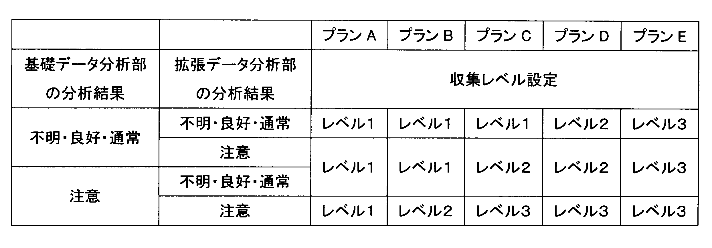
図8は、契約プラン設定部MCTL04において契約プランを設定する操作画面の例を示す。モニタリングツールMTの機能は、例えば、パーソナルコンピュータにインストールされたソフトウェアをパーソナルコンピュータが実行することで実現される。例えば、操作者は、操作画面MDSPに表示されたUI(ユーザインターフェース)画面をキーボードやマウスなどを使って操作することで、モニタリングツールMTにおける情報の入力を行うことができる。図8の例では、各契約プランのカラムにチェックボックスがあり、いずれかのチェックボックスを選択することで、対象となるユーザのプリンタPRにおいて適用すべき収集レベル設定の調整パターンを設定することができる。図8は、一例として、プランBを選択した状態を示している。 Figure 8 shows an example of an operation screen for setting a contract plan in the contract plan setting unit MCTL04. The functions of the monitoring tool MT are realized, for example, by a personal computer executing software installed on the personal computer. For example, an operator can input information in the monitoring tool MT by operating a UI (user interface) screen displayed on the operation screen MDSP using a keyboard, mouse, etc. In the example of Figure 8, there are check boxes in the column for each contract plan, and by selecting one of the check boxes, an adjustment pattern for the collection level setting to be applied to the target user's printer PR can be set. Figure 8 shows the state in which plan B has been selected, as an example.
なお、本実施例では、モニタリングツールMTがパーソナルコンピュータで構成される例を示したが、モニタリングツールMTは、例えば操作画面を有する専用デバイスであっても構わない。 In this embodiment, an example is shown in which the monitoring tool MT is configured as a personal computer, but the monitoring tool MT may also be, for example, a dedicated device having an operation screen.
また、表8(及び図8)の例では、プランA及びプランEでは、収集レベル設定は、動作履歴データの分析結果によらずに一定である。このように、予め設定された収集レベル設定の複数の調整パターンには、動作履歴データの分析結果に基づいて収集レベル設定が動的に調整されない調整パターンが含まれていてもよい。 Also, in the example of Table 8 (and FIG. 8), in Plan A and Plan E, the collection level setting is constant regardless of the analysis results of the operation history data. In this way, the multiple adjustment patterns of the pre-set collection level setting may include an adjustment pattern in which the collection level setting is not dynamically adjusted based on the analysis results of the operation history data.
<制御部の動作の説明:図9>
本実施例におけるエンジン制御部ECTL、サーバ制御部SCTL、及びモニタリングツール制御部MCTLの動作について図9を用いて説明する。図9は、本実施例におけるエンジン制御部ECTL、サーバ制御部SCTL、及びモニタリングツール制御部MCTLの動作を説明するためのフローチャートである。
<Explanation of the operation of the control unit: Figure 9>
The operations of the engine control unit ECTL, the server control unit SCTL, and the monitoring tool control unit MCTL in this embodiment will be described with reference to Fig. 9. Fig. 9 is a flowchart for explaining the operations of the engine control unit ECTL, the server control unit SCTL, and the monitoring tool control unit MCTL in this embodiment.
図9(a)のフローチャートの手順は、例えばプリンタPRの設置時に、モニタリングツール制御部MCTL(モニタリングツールMT)において開始される、契約プラン情報を設定する手順である。具体的には、例えばディーラの操作者によるモニタリングツールMTにおける操作に基づいて、契約プラン設定部MCTL04が、ディーラとユーザとが結んでいる契約プラン(契約内容)に応じて選択された契約プラン情報を設定する(S101)。 The procedure in the flowchart in FIG. 9(a) is a procedure for setting contract plan information that is initiated in the monitoring tool control unit MCTL (monitoring tool MT) when, for example, the printer PR is installed. Specifically, for example, based on the operation of the monitoring tool MT by an operator at a dealer, the contract plan setting unit MCTL04 sets contract plan information selected according to the contract plan (contract details) between the dealer and the user (S101).
図9(b)のフローチャートの手順は、図6のフローチャートの手順と同様の、エンジン制御部ECTL(プリンタエンジンPR03)がプリント指示を受けると開始される手順である。図9(b)のフローチャートにおいて、実施例1で説明した図6のフローチャートの処理と同一又は対応する処理には同一のステップ番号を付して、適宜説明を省略する。本実施例では、収集レベル設定決定部SCTL05が契約プラン設定部MCTL04から契約プラン情報を取得する手順(S102)が追加されている点が実施例1と異なる。また、本実施例では、S007の処理において、取得された契約プラン情報の分析が行われる点が実施例1と異なる。 The procedure in the flowchart of FIG. 9(b) is similar to the procedure in the flowchart of FIG. 6, and is initiated when the engine control unit ECTL (printer engine PR03) receives a print instruction. In the flowchart of FIG. 9(b), the same step numbers are used for processes that are the same as or correspond to the processes in the flowchart of FIG. 6 described in the first embodiment, and descriptions are omitted as appropriate. This embodiment differs from the first embodiment in that a procedure (S102) is added in which the collection level setting determination unit SCTL05 acquires contract plan information from the contract plan setting unit MCTL04. This embodiment also differs from the first embodiment in that the acquired contract plan information is analyzed in the process of S007.
具体的には、サーバ制御部SCTLは、基礎データ分析部SCTL01、拡張データ分析部SCTL02において、収集レベル設定に応じて、基礎データ収集部ECTL05、拡張データ収集部ECTL06から特徴量、画像データをそれぞれ取得する(S005、S006L1~S006L3)。また、サーバ制御部SCTLは、収集レベル設定決定部SCTL05において、契約プラン設定部MCTL04から契約プラン情報を取得する(S102)。次に、サーバ制御部SCTLは、実施例1と同様に、基礎データ分析部SCTL01、拡張データ分析部SCTL02において、受信した特徴量及び画像データに基づいて、画像不良の分析を行う(S007)。また、サーバ制御部SCTLは、収集レベル設定決定部SCTL05において、契約プラン設定部MCTL04から取得された契約プラン情報を分析して、収集レベル設定の調整パターンを判断(決定)する(S007)。 Specifically, the server control unit SCTL acquires features and image data from the basic data collection unit ECTL05 and the extended data collection unit ECTL06 in the basic data analysis unit SCTL01 and the extended data analysis unit SCTL02, respectively, depending on the collection level setting (S005, S006L1 to S006L3). The server control unit SCTL also acquires contract plan information from the contract plan setting unit MCTL04 in the collection level setting determination unit SCTL05 (S102). Next, the server control unit SCTL analyzes image defects based on the received features and image data in the basic data analysis unit SCTL01 and the extended data analysis unit SCTL02, as in the first embodiment (S007). The server control unit SCTL also analyzes the contract plan information acquired from the contract plan setting unit MCTL04 in the collection level setting determination unit SCTL05, and determines (determines) the adjustment pattern for the collection level setting (S007).
そして、サーバ制御部SCTLは、収集レベル設定決定部SCTL05において、基礎データ及び拡張データの分析結果と、契約プラン情報に応じて選択された収集レベル設定の調整パターンと、に基づいて、収集レベル設定を決定し、エンジン制御部ECTLに送信する(S010)。本実施例では、収集レベル設定決定部SCTL05は、表8に示す基準に従って収集レベル設定を決定する。S008、S009、S020、S021の処理は実施例1と同様である。 Then, the server control unit SCTL determines the collection level setting in the collection level setting determination unit SCTL05 based on the analysis results of the basic data and extended data and the collection level setting adjustment pattern selected according to the contract plan information, and transmits it to the engine control unit ECTL (S010). In this embodiment, the collection level setting determination unit SCTL05 determines the collection level setting according to the criteria shown in Table 8. The processes of S008, S009, S020, and S021 are the same as those in the first embodiment.
なお、説明の便宜上、S008~S009の手順と、S010~S011の手順と、を直列的に記載しているが、これらの手順は上記とは逆の順番で実行されてもよいし、実質的に同時に実行されてもよい。 For ease of explanation, steps S008 to S009 and steps S010 to S011 are described in series, but these steps may be executed in the reverse order or may be executed substantially simultaneously.
このように、本実施例では、動作履歴データの分析結果と、収集レベル設定の調整パターンを指定する情報(本実施例では、保守設定情報としての契約プラン情報により予め設定された条件)と、に基づいて、収集レベル設定を動的に調整する。これにより、動作履歴などに応じた求められる分析精度の変更(変化)などに柔軟に対応しながら、個々のユーザの要望に合わせて、運用コストを最適化することができる。 In this manner, in this embodiment, the collection level setting is dynamically adjusted based on the analysis results of the operation history data and information specifying the adjustment pattern for the collection level setting (in this embodiment, conditions preset by the contract plan information as the maintenance setting information). This makes it possible to optimize operational costs in accordance with the needs of individual users while flexibly responding to changes (changes) in the required analytical accuracy according to the operation history, etc.
なお、本実施例では、契約プラン設定部MCTL04は、モニタリングツールMTに設けられていたが、これに限られるものではなく、例えば、エンジン制御部ECTLに設けられていてもよい。この場合、モニタリングツールMTからではなく、プリンタPRの操作表示部PR02から契約プラン情報を設定することができる。また、例えば、画像形成システム100は、別のクラウドシステム(契約システム)と連携する形で、契約プラン情報を取得してもよい。
In this embodiment, the contract plan setting unit MCTL04 is provided in the monitoring tool MT, but this is not limited to this and may be provided in the engine control unit ECTL, for example. In this case, the contract plan information can be set from the operation display unit PR02 of the printer PR, rather than from the monitoring tool MT. Also, for example, the
[実施例3]
次に、本発明の他の実施例について説明する。本実施例の画像形成システム及び画像形成装置の基本的な構成及び動作は、実施例1、2の画像形成システム及び画像形成装置のものと同じである。したがって、本実施例の画像形成システム及び画像形成装置において、実施例1、2のものと同一又は対応する機能あるいは構成を有する要素については、実施例1、2と同一の符号を付して詳しい説明は省略する。
[Example 3]
Next, another embodiment of the present invention will be described. The basic configuration and operation of the image forming system and image forming apparatus of this embodiment are the same as those of the image forming system and image forming apparatus of
本実施例では、画像形成システム100は、動作履歴データの分析結果と、対策内容を通知する通知先となる通知クライアント装置を指定する情報としてのサービスマンの出動可否情報と、に基づいて、適切な通知クライアント装置を決定する。また、本実施例では、画像形成システム100は、決定された通知クライアント装置に応じて、対策内容を変更する。更に、本実施例では、決定された通知クライアント装置に応じて、収集レベル設定を変更する。
In this embodiment, the
<機能ブロックの説明:図10>
図10は、本実施例におけるエンジン制御部ECTL、サーバ制御部SCTL及びモニタリングツール制御部MCTLの機能ブロックを示す模式図である。本実施例は、主に、次の3点が実施例2と異なる。まず、画像形成システム100が、出動可否情報設定部MCTL05を使用して、保守設定情報としての、サービスマンがすぐに対応できるか否かといったサービスマンの出動可否情報を取得する点である。次に、画像形成システム100が、対策内容決定部(通知先決定部)SCTL03において、保守設定情報としての契約プラン情報及び出動可否情報を受信し、分析する点である。最後に、画像形成システム100が、収集レベル設定決定部SCTL05において、保守設定情報としての契約プラン情報及び出動可否情報を受信し、分析する点である。
<Explanation of functional blocks: Figure 10>
10 is a schematic diagram showing the functional blocks of the engine control unit ECTL, the server control unit SCTL, and the monitoring tool control unit MCTL in this embodiment. This embodiment is mainly different from the second embodiment in the following three points. First, the
本実施例では、モニタリングツール制御部MCTLは、収集レベル設定の調整パターンを指定する情報を取得する機能ブロックとして、契約プラン設定手段としての契約プラン設定部MCTL04を有する。また、本実施例では、モニタリングツール制御部MCTLは、対策内容の通知クライアント装置を指定する情報を取得する機能ブロックとして、出動可否情報設定手段(通知先指定手段)としての出動可否情報設定部MCTL05を有する。契約プラン設定部MCTL04及び出動可否情報設定部MCTL05は、保守設定情報収集手段としての保守設定情報収集部MCTL06を構成する。このように、本実施例では、保守設定情報収集部MCTL06は、実施例2で説明した契約プラン情報を契約プラン設定部MCTL04で収集することに加え、出動可否情報設定部MCTL05で出動可否情報を収集する。契約プラン情報、出動可否情報は、それぞれ予め設定された画像形成装置の保守に関する条件に関する情報である保守設定情報の一例である。 In this embodiment, the monitoring tool control unit MCTL has a contract plan setting unit MCTL04 as a contract plan setting means, as a functional block that acquires information specifying the adjustment pattern of the collection level setting. In addition, in this embodiment, the monitoring tool control unit MCTL has a dispatch feasibility information setting unit MCTL05 as a dispatch feasibility information setting means (notification destination designation means) as a functional block that acquires information specifying the notification client device of the countermeasure content. The contract plan setting unit MCTL04 and the dispatch feasibility information setting unit MCTL05 constitute the maintenance setting information collection unit MCTL06 as a maintenance setting information collection means. Thus, in this embodiment, the maintenance setting information collection unit MCTL06 collects the contract plan information described in the second embodiment with the contract plan setting unit MCTL04, and also collects the dispatch feasibility information with the dispatch feasibility information setting unit MCTL05. The contract plan information and the dispatch feasibility information are examples of maintenance setting information, which is information regarding the conditions related to the maintenance of the image forming device that have been set in advance.
本実施例では、出動可否情報設定部MCTL05は、サービスマンが出動可能なタイミングに関する情報としての曜日と時間帯に関する情報を取得する。例えば、プリンタPRの設置時に、ディーラの操作者が、モニタリングツールMTにおける操作に基づいて、サービスマンが出動可能な曜日と時間帯に関する情報を設定する。図11は、サービスマンが出動可能な曜日と時間帯に関する情報を設定する操作画面の例を示す。図11の例では、各曜日に対するチェックボックスがあり、いずれかのチェックボックスを選択することで、対象となるユーザのプリンタPRにおいて適用すべきサービスマンが出動可能な曜日を設定することができる。また、各曜日に対して時間帯を選択する欄があり、いずれかの時間帯(図示の例では1時間毎)を選択することで、対象となるユーザのプリンタPRにおいて適用すべきサービスマンが出動可能な時間帯を設定することができる。図11は、月曜日から金曜日のAM10:00~PM5:00の間にサービスマンが出動可能と設定した状態を示している。 In this embodiment, the dispatch availability information setting unit MCTL05 acquires information on the days of the week and the time periods as information on the timing when a serviceman can be dispatched. For example, when installing the printer PR, the dealer's operator sets information on the days of the week and the time periods when a serviceman can be dispatched based on the operation of the monitoring tool MT. FIG. 11 shows an example of an operation screen for setting information on the days of the week and the time periods when a serviceman can be dispatched. In the example of FIG. 11, there are check boxes for each day of the week, and by selecting one of the check boxes, it is possible to set the days of the week when a serviceman to be applied to the printer PR of the target user can be dispatched. In addition, there is a column for selecting a time period for each day of the week, and by selecting one of the time periods (every hour in the illustrated example), it is possible to set the time period when a serviceman to be applied to the printer PR of the target user can be dispatched. FIG. 11 shows a state in which it is set that a serviceman can be dispatched between 10:00 AM and 5:00 PM from Monday to Friday.
サーバ制御部SCTLは、対策内容決定部SCTL03において、出動可否情報設定部MCTL05から受信した出動可否情報(曜日、時間帯)と、現在日時(曜日、時刻)と、に基づいて、「保守状態」を決定する。本実施例では、現在日時がサービスマンの出動可能な曜日及び時間帯に該当する場合、保守状態を「出動可能」とする。一方、現在日時がサービスマンの出動可能な曜日及び時間帯に該当しない場合、保守状態を「出動不可」とする。 The server control unit SCTL determines the "maintenance status" in the countermeasure content determination unit SCTL03 based on the dispatch availability information (day of the week, time period) received from the dispatch availability information setting unit MCTL05 and the current date and time (day of the week, time). In this embodiment, if the current date and time corresponds to a day of the week and time period when a serviceman is available for dispatch, the maintenance status is set to "dispatch available". On the other hand, if the current date and time does not correspond to a day of the week and time period when a serviceman is available for dispatch, the maintenance status is set to "not dispatchable".
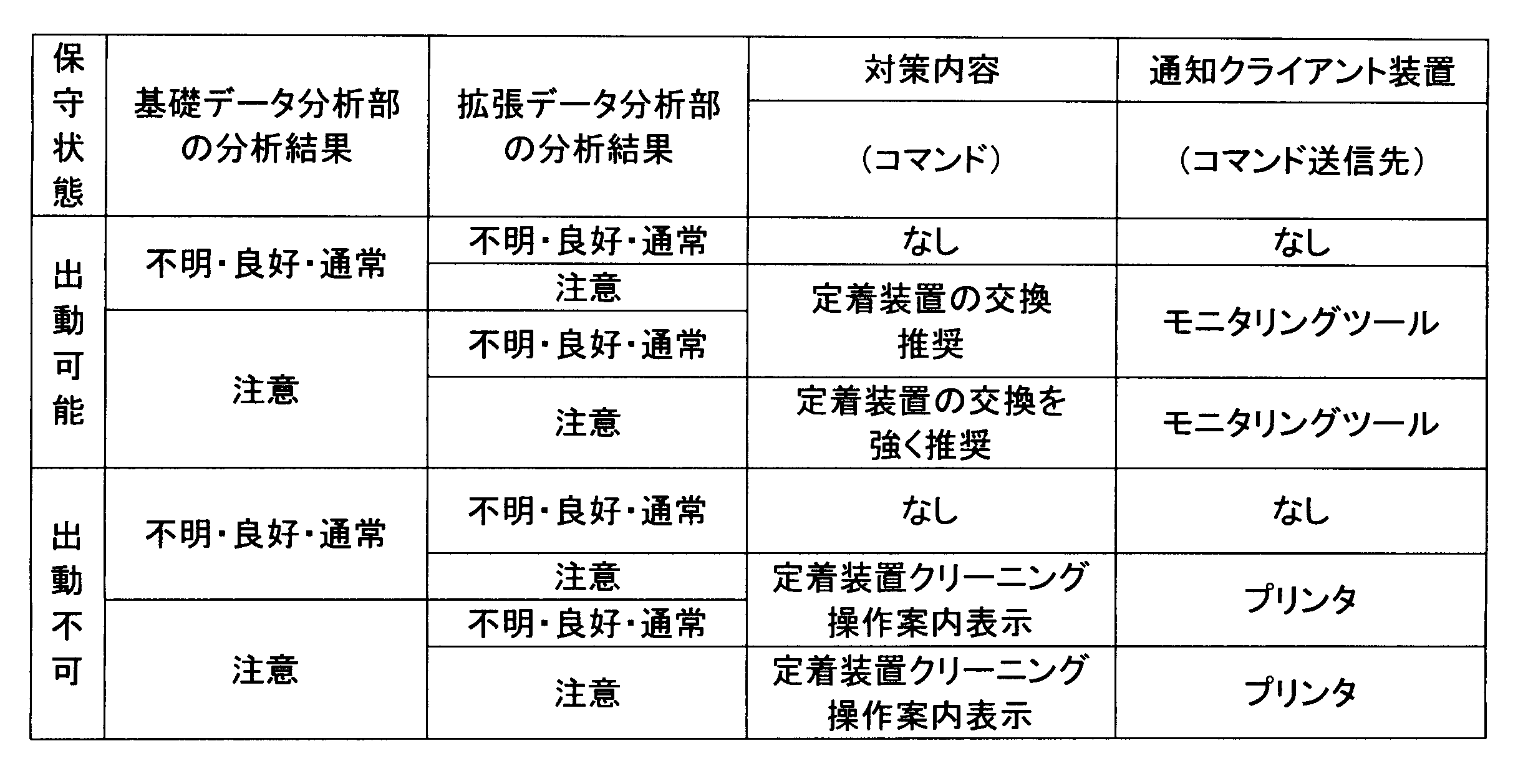
また、本実施例では、サーバ制御部SCTLは、対策内容決定部SCTL03において、基礎データ及び拡張データの分析結果と、上記保守状態と、に基づいて、対策内容及び通知クライアント装置を決定する。このように、本実施例では、対策内容決定部SCTL03は、対策内容決定手段としての機能を有すると共に、通知先決定手段としての機能を有する。本実施例では、対策内容決定部SCTL03は、表9に示す基準に従い、対策内容及び通知クライアント装置を決定する。保守状態が「出動可能」の場合は、画像不良の状態、具体的には実施例1、2で説明した基礎データ及び拡張データの分析結果に応じて、「定着装置の交換推奨」や「定着装置の交換を強く推奨」コマンドをモニタリングツールMTに送信する。つまり、この場合は、通知クライアント装置としてのモニタリングツールMTへ対策内容を示すコマンドが伝達される。一方、保守状態が「出動不可」の場合は、画像不良の状態、具体的には実施例1、2で説明した基礎データ及び拡張データの分析結果に応じて、定着装置クリーニング操作案内表示コマンドをプリンタPRに送信する。つまり、この場合は、通知クライアント装置としてのプリンタPRへ対策内容を示すコマンドが伝達される。 In addition, in this embodiment, the server control unit SCTL determines the countermeasure content and the notification client device in the countermeasure content determination unit SCTL03 based on the analysis results of the basic data and the extended data and the above maintenance status. Thus, in this embodiment, the countermeasure content determination unit SCTL03 has a function as a countermeasure content determination means and also a function as a notification destination determination means. In this embodiment, the countermeasure content determination unit SCTL03 determines the countermeasure content and the notification client device according to the criteria shown in Table 9. When the maintenance status is "dispatchable", a "fixing device replacement recommended" or "fixing device replacement strongly recommended" command is sent to the monitoring tool MT according to the image defect state, specifically the analysis results of the basic data and extended data described in Examples 1 and 2. In other words, in this case, a command indicating the countermeasure content is transmitted to the monitoring tool MT as the notification client device. On the other hand, when the maintenance status is "dispatchable", a fixing device cleaning operation guide display command is sent to the printer PR according to the image defect state, specifically the analysis results of the basic data and extended data described in Examples 1 and 2. In other words, in this case, a command indicating the countermeasures will be transmitted to the printer PR as the notification client device.
本実施例では、「出動可能」の場合は、サーバ制御部SCTLは、実施例1、2と同様にして、ネットワークを経由して、モニタリング制御部MCTLが有する対策内容受信部MCTL01に対策内容を送信する。一方、本実施例では、「出動不可」の場合は、サーバ制御部SCTLは、対策内容送信部SCTL04によりエンジン制御部ECTLへ対策内容を送信する。つまり、この場合、対策内容送信部SCTL04は、ビデオコントローラPR01が有する通信部PCTL01を経由して、エンジン制御部ECTLが有する対策内容受信手段としての対策内容受信部ECTL09へ対策内容を送信する。対策内容受信部ECTL09は、受信した対策内容を、エンジン制御部ECTLが有する対策内容反映手段としての対策内容反映部ECTL10へ送信する。対策内容反映部ECTL10は、受信した対策内容に基づいて、プリンタPRの操作表示部PR02に対策内容を表示してユーザに通知するように制御する。 In this embodiment, in the case of "dispatch possible", the server control unit SCTL transmits the countermeasure content to the countermeasure content receiving unit MCTL01 of the monitoring control unit MCTL via the network, as in the first and second embodiments. On the other hand, in this embodiment, in the case of "dispatch not possible", the server control unit SCTL transmits the countermeasure content to the engine control unit ECTL via the countermeasure content transmitting unit SCTL04. That is, in this case, the countermeasure content transmitting unit SCTL04 transmits the countermeasure content to the countermeasure content receiving unit ECTL09 as a countermeasure content receiving means of the engine control unit ECTL via the communication unit PCTL01 of the video controller PR01. The countermeasure content receiving unit ECTL09 transmits the received countermeasure content to the countermeasure content reflecting unit ECTL10 as a countermeasure content reflecting means of the engine control unit ECTL. The countermeasure content reflecting unit ECTL10 controls the printer PR to display the countermeasure content on the operation display unit PR02 of the printer PR based on the received countermeasure content and notify the user.
「出動不可」の場合の対策内容としては、例えば、画像不良の解消又は低減のための処置を、典型的にはユーザの操作に基づいて実行することが挙げられる。具体的には、例えば、対策内容の表示において、プリンタPRに予め備わっている定着装置30のクリーニング操作(クリーニングモード)の実行をユーザに促すことができる。この場合、例えば、対策内容反映部ECTL10は、定着装置30のクリーニング操作を実行するためのガイダンスを操作表示部PR02に表示するコマンドを、操作表示部PR02に送信する。定着装置30のクリーニング操作の具体的な方法としては、画像印字率(画像比率)の高い画像(ベタ黒画像)を両面プリントにより記録材Sの両面に形成するといった方法が挙げられる。
In the case of "unavailable", countermeasures include, for example, measures to eliminate or reduce image defects, typically implemented based on user operation. Specifically, for example, the countermeasures display can prompt the user to execute a cleaning operation (cleaning mode) of the fixing
これにより、サービスマンが出動できない曜日、時間帯など、その他の事情によりサービスマンがすぐに出動できない状況下においても、画像不良の発生レベルを緩和することができる。また、これにより、サービス出動が要請される可能性を抑えることも期待できる。 This makes it possible to reduce the occurrence of image defects even in situations where a service technician cannot be dispatched immediately due to certain days of the week, time of day, or other reasons. It is also expected that this will reduce the possibility of a service technician being called out.
なお、本実施例では、定着装置30のクリーニングを行う方法としてユーザの操作を伴う方法を例として挙げたが、ユーザの操作を伴わない他の方法で画像不良の解消又は低減を図っても構わない。具体的には、画像不良が目立たなくなるようにエンジン制御部ECTLが画像濃度の微調整を行うことなどが例として挙げられる。
In this embodiment, a method involving user operation has been given as an example of a method for cleaning the fixing
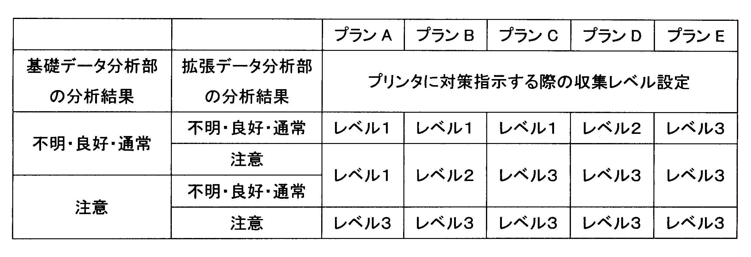
また、本実施例では、サーバ制御部SCTLは、収集レベル設定決定部SCTL05において、対策内容が通知される通知クライアント装置に応じて、収集レベル設定を変更する。本実施例では、保守状態が「出動可能」であり、対策内容をモニタリングツールMTへ送信する場合は、収集レベル設定決定部SCTL05は、実施例2と同様に表8に示す基準に従って収集レベル設定を決定する。一方、本実施例では、保守状態が「出動不可」であり、対策指示をプリンタPRに送信する場合は、表10に示す基準に従って収集レベル設定を決定する。表10に示す収集レベル設定は、表8に示すものに比べると、一部の収集レベルの値が高く設定されている。これにより、プリンタPRに備えられた検知手段により取得したデータを用いて本システムによって自律的に対策を行うにあたって、より精度の高いデータを取得し、分析手段による判断の正確性を高めることができる。また、分析精度を高めると、画像不良の状態の判断結果が良化する傾向がある場合には、分析精度を高めることでサービス出動が要請される可能性を抑えることも期待できる。 In this embodiment, the server control unit SCTL changes the collection level setting in the collection level setting determination unit SCTL05 according to the notification client device to which the countermeasure content is notified. In this embodiment, when the maintenance status is "dispatch possible" and the countermeasure content is sent to the monitoring tool MT, the collection level setting determination unit SCTL05 determines the collection level setting according to the criteria shown in Table 8 as in the second embodiment. On the other hand, in this embodiment, when the maintenance status is "dispatch not possible" and the countermeasure instruction is sent to the printer PR, the collection level setting is determined according to the criteria shown in Table 10. The collection level settings shown in Table 10 have some collection level values set higher than those shown in Table 8. This makes it possible to obtain more accurate data and improve the accuracy of judgment by the analysis means when the system autonomously takes countermeasures using data obtained by the detection means provided in the printer PR. In addition, if the judgment result of the image defect state tends to improve when the analysis accuracy is improved, it is expected that the possibility of a service dispatch being requested can be reduced by improving the analysis accuracy.
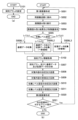
<制御部の動作の説明:図12>
本実施例におけるエンジン制御部ECTL、サーバ制御部SCTL、及びモニタリングツール制御部MCTLの動作について図12を用いて説明する。図12は、本実施例におけるエンジン制御部ECTL、サーバ制御部SCTL、及びモニタリングツール制御部MCTLの動作を説明するためのフローチャートである。
<Explanation of the operation of the control unit: FIG. 12>
The operations of the engine control unit ECTL, the server control unit SCTL, and the monitoring tool control unit MCTL in this embodiment will be described with reference to Fig. 12. Fig. 12 is a flowchart for explaining the operations of the engine control unit ECTL, the server control unit SCTL, and the monitoring tool control unit MCTL in this embodiment.
図12(a)のフローチャートの手順は、例えばプリンタPRの設置時に、モニタリングツール制御部MCTL(モニタリングツールMT)において開始される、保守設定情報(契約プラン情報、出動可否情報)を設定する手順である。具体的には、例えばディーラの操作者によるモニタリングツールMTにおける操作に基づいて、契約プラン設定部MCTL04は、契約プラン情報を設定すると共に、出動可否情報設定部MCTL05が出動可否情報を設定する(S201)。 The procedure in the flowchart in FIG. 12(a) is a procedure for setting maintenance setting information (contract plan information, dispatch feasibility information) that is initiated in the monitoring tool control unit MCTL (monitoring tool MT) when, for example, the printer PR is installed. Specifically, for example, based on the operation of the monitoring tool MT by an operator at a dealer, the contract plan setting unit MCTL04 sets the contract plan information, and the dispatch feasibility information setting unit MCTL05 sets the dispatch feasibility information (S201).
図12(b)のフローチャートの手順は、図6、図9(b)のフローチャートと同様の、エンジン制御部ECTL(プリンタエンジンPR03)がプリント指示を受けると開始される手順である。図12(b)のフローチャートにおいて、実施例1、2でそれぞれ説明した図6、図9(b)のフローチャートの処理と同一又は対応する処理には同一のステップ番号を付して、適宜説明を省略する。本実施例では、対策内容決定部SCTL、収集レベル設定決定部SCTL05が保守設定情報(契約プラン情報、出動可否情報)を取得する手順(S202)が追加されている点が実施例1、2と異なる。また、本実施例では、S007の処理において、取得された保守設定情報(契約プラン情報、出動可否情報)の分析が行われる点が実施例1、2と異なる。また、本実施例では、対策内容(通知先)決定部SCTL03が出動可否情報に基づいて通知クライアント装置を決定する手順(S203)が追加されている点が実施例1、2と異なる。また、本実施例では、通知クライアント装置に応じて対策内容を決定して送信する手順(S008P、S008P、S008M、S009M)が実施例1、2と異なる。また、本実施例では、S010の処理において、通知クライアント装置に応じて収集レベル設定が決定される点が実施例1、2と異なる。 The procedure of the flowchart in FIG. 12(b) is the same as that of the flowchart in FIG. 6 and FIG. 9(b), and is a procedure that is started when the engine control unit ECTL (printer engine PR03) receives a print instruction. In the flowchart in FIG. 12(b), the same step numbers are given to processes that are the same as or correspond to the processes of the flowchart in FIG. 6 and FIG. 9(b) described in the first and second embodiments, respectively, and the explanation is omitted as appropriate. In this embodiment, the countermeasure content determination unit SCTL and the collection level setting determination unit SCTL05 are added with a procedure (S202) for acquiring maintenance setting information (contract plan information, dispatch availability information). In addition, in this embodiment, the acquired maintenance setting information (contract plan information, dispatch availability information) is analyzed in the process of S007, which is different from the first and second embodiments. In this embodiment, the countermeasure content (notification destination) determination unit SCTL03 is added with a procedure (S203) for determining the notification client device based on the dispatch availability information. In addition, in this embodiment, the procedure (S008P, S008P, S008M, S009M) for determining and transmitting the countermeasure content according to the notification client device differs from that of the first and second embodiments. In addition, in this embodiment, the process of S010 differs from that of the first and second embodiments in that the collection level setting is determined according to the notification client device.
具体的には、サーバ制御部SCTLは、基礎データ分析部SCTL01、拡張データ分析部SCTL02において、収集レベル設定に応じて、基礎データ収集部ECTL05、拡張データ収集部ECTL06から特徴量、画像データをそれぞれ取得する(S005、S006L1~S006L3)。また、サーバ制御部SCTLは、対策内容決定部SCTL03、収集レベル設定決定部SCTL05において、契約プラン設定部MCTL04及び出動可否情報設定部MCTL05から、契約プラン情報及び出動可否情報を取得する(S202)。次に、サーバ制御部SCTLは、実施例1、2と同様に、基礎データ分析部SCTL01、拡張データ分析部SCTL02において、受信した特徴量及び画像データに基づいて、画像不良の分析を行う(S007)。また、サーバ制御部SCTLは、対策内容決定部SCTL03において、出動可否情報設定部MCTL05から取得された手動可否情報を分析して、保守状態を判断(決定)する(S007)。更に、サーバ制御部SCTLは、収集レベル設定決定部SCTL05において、契約プラン設定部MCTL04から取得された契約プラン情報を分析して、収集レベル設定の調整パターンを判断(決定)する(S007)。 Specifically, the server control unit SCTL acquires features and image data from the basic data collection unit ECTL05 and the extended data collection unit ECTL06 in the basic data analysis unit SCTL01 and the extended data analysis unit SCTL02, respectively, depending on the collection level setting (S005, S006L1-S006L3). The server control unit SCTL also acquires contract plan information and dispatch feasibility information from the contract plan setting unit MCTL04 and the dispatch feasibility information setting unit MCTL05 in the countermeasure content determination unit SCTL03 and the collection level setting determination unit SCTL05 (S202). Next, the server control unit SCTL analyzes image defects based on the received features and image data in the basic data analysis unit SCTL01 and the extended data analysis unit SCTL02, as in the first and second embodiments (S007). In addition, the server control unit SCTL, in the countermeasure content determination unit SCTL03, analyzes the manual availability information acquired from the dispatch availability information setting unit MCTL05 to determine (decide) the maintenance status (S007). Furthermore, the server control unit SCTL, in the collection level setting determination unit SCTL05, analyzes the contract plan information acquired from the contract plan setting unit MCTL04 to determine (decide) the adjustment pattern for the collection level setting (S007).
また、サーバ制御部SCTLは、対策内容決定部SCTL03において、出動可否情報の分析結果である保守状態に応じて、通知クライアント装置をプリンタPRとするかモニタリングツールMTとするかを選択(決定)する(S203)。対策内容決定部SCTL03は、保守状態が「出動可能」である場合は、対策内容を通知する通知先となる通知クラインと装置としてモニタリングツールMTを選択する。そして、サーバ制御部SCTLは、対策内容送信部SCTL04において、対策内容としてサービスマンが実行すべき対策の指示をモニタリングツールMTへ通知する(S008M)。これにより、モニタリングツールMTは、対策内容受信部MCTL01において、対策内容を受信する(S009M)。また、モニタリングツールMTは、対策内容反映部MCTL02、表示制御部MCTL03において、実施例1、2と同様にして、対策内容をモニタリングツールMTの操作表示部MDSPに表示するように処理を行う(S009M)。一方、対策内容決定部SCTL03は、保守状態が「出動不可」である場合は、対策内容を通知する通知先となる通知クライアント装置としてプリンタPRを選択する。そして、サーバ制御部SCTLは、対策内容送信部SCTL04において、対策内容としてユーザが実行すべき対策の指示をプリンタPRへ通知する(S008P)。これにより、プリンタPRは、対策内容受信部ECTL09において、対策内容を受信する(S009P)。また、プリンタPRは、対策内容反映部ECTL10において、対策内容をプリンタPRの操作表示部PR02に表示するように処理を行う(S009M)。この場合、対策内容反映部ECTL10は、例えば、定着装置30のクリーニングの操作方法をユーザに行わせるためのガイダンスを操作表示部PR02に表示するように制御する。本実施例では、対策内容決定部SCTL03は、表9に示す基準に従って対策内容と通知クライアント装置を決定する。
In addition, the server control unit SCTL selects (determines) whether the notification client device is the printer PR or the monitoring tool MT in the countermeasure content determination unit SCTL03 according to the maintenance status, which is the analysis result of the dispatch readiness information (S203). If the maintenance status is "dispatchable", the countermeasure content determination unit SCTL03 selects the monitoring tool MT as the notification client device to which the countermeasure content is to be notified. Then, the server control unit SCTL notifies the monitoring tool MT of the countermeasure content, in the countermeasure content transmission unit SCTL04, the instructions of the countermeasure to be executed by the serviceman as the countermeasure content (S008M). As a result, the monitoring tool MT receives the countermeasure content in the countermeasure content reception unit MCTL01 (S009M). In addition, the monitoring tool MT performs processing in the countermeasure content reflection unit MCTL02 and the display control unit MCTL03 to display the countermeasure content on the operation display unit MDSP of the monitoring tool MT in the same manner as in the first and second embodiments (S009M). On the other hand, if the maintenance status is "unavailable", the countermeasure content determination unit SCTL03 selects the printer PR as the notification client device to which the countermeasure content is to be notified. Then, the server control unit SCTL notifies the printer PR of the countermeasure content to be executed by the user in the countermeasure content transmission unit SCTL04 (S008P). As a result, the printer PR receives the countermeasure content in the countermeasure content reception unit ECTL09 (S009P). The printer PR also performs processing in the countermeasure content reflection unit ECTL10 to display the countermeasure content on the operation display unit PR02 of the printer PR (S009M). In this case, the countermeasure content reflection unit ECTL10 controls the operation display unit PR02 to display, for example, guidance for the user to perform the operation method for cleaning the fixing
また、サーバ制御部SCTLは、収集レベル設定決定部SCTL05において、保守状態(通知クライアント装置)と、基礎データ及び拡張データの分析結果と、契約プラン情報と、に基づいて、収集レベル設定を決定する(S010)。本実施例では、収集レベル設定決定部SCTL05は、保守状態が「出動可能」であり通知クライアント装置がモニタリングツールMTである場合は、実施例2と同様に表8に示す基準に従って収集レベル設定を決定する。また、本実施例では、収集レベル設定決定部SCTL05は、保守状態が「出動不可」であり通知クライアント装置がプリンタPRである場合は、表10に示す基準に従って収集レベル設定を決定する。S011、S012,S020、S021の処理は実施例2と同様である。 The server control unit SCTL determines the collection level setting in the collection level setting determination unit SCTL05 based on the maintenance status (notification client device), the analysis results of the basic data and extended data, and the contract plan information (S010). In this embodiment, if the maintenance status is "dispatchable" and the notification client device is the monitoring tool MT, the collection level setting determination unit SCTL05 determines the collection level setting according to the criteria shown in Table 8, as in the second embodiment. In this embodiment, if the maintenance status is "dispatchable" and the notification client device is the printer PR, the collection level setting determination unit SCTL05 determines the collection level setting according to the criteria shown in Table 10. The processes of S011, S012, S020, and S021 are the same as those in the second embodiment.
なお、説明の便宜上、S203~S009P、S009Mの手順と、S010~S011の手順と、を直列的に記載しているが、これらの手順は上記とは逆の順番で実行されてもよいし、実質的に同時に実行されてもよい。 For ease of explanation, steps S203 to S009P and S009M and steps S010 to S011 are described in series, but these steps may be executed in the reverse order or may be executed substantially simultaneously.
このように、本実施例では、動作履歴データの分析結果と、対策内容の通知クライアント装置を指定する情報(本実施例では、保守設定情報としての出動可否情報により予め設定された条件)と、に基づいて、対策内容及び通知クライアント装置を決定する。つまり、本実施例では、サービスマンの予定を考慮したうえで、適切な対策内容及び通知クライアント装置を決定することができる。これにより、サービスマンが出動できない状況下においても、画像不良の解消又は低減のための処置をユーザ自身で行うことが可能となる。更に、サービス出動が要請される可能性を抑えられるため、ディーラのサービスコストを抑制することも期待できる。その際に、サービスマンが出動できない状況下で対策を行う場合は動作履歴データの収集レベルを上げて、判断の正確性を高めることができる。 In this way, in this embodiment, the countermeasure content and the notification client device are determined based on the analysis results of the operation history data and information specifying the notification client device for the countermeasure content (in this embodiment, the condition is set in advance based on the dispatch availability information as the maintenance setting information). In other words, in this embodiment, appropriate countermeasure content and notification client device can be determined after taking into consideration the schedule of the serviceman. This allows the user to take measures to eliminate or reduce image defects even in situations where a serviceman cannot be dispatched. Furthermore, since the possibility of a service dispatch being requested is reduced, it is expected that the service costs of the dealer can be reduced. In that case, if countermeasures are taken in a situation where a serviceman cannot be dispatched, the collection level of operation history data can be increased to improve the accuracy of the judgment.
なお、本実施例では、サービスマンが出動可能な曜日と時間帯とを固定的に設定した例を示したが、サーバとモニタリングツールの対話(通信)によりリアルタイムにサービスマンの出動可否状態を更新してもよい。 In this embodiment, the days of the week and times when a serviceman is available are set to a fixed number, but the availability of a serviceman may be updated in real time through dialogue (communication) between the server and the monitoring tool.
また、本実施例では、契約プラン設定部MCTL04、出動可否情報設定部MCTL05は、モニタリングツールMTに設けられていたが、これに限られるものではなく、例えば、エンジン制御部ECTLに設けられていてもよい。この場合、モニタリングツールMTからではなく、プリンタPRの操作表示部PR02から契約プラン情報、動作可否情報を設定することができる。また、例えば、画像形成システム100は、別のクラウドシステム(契約システム)と連携する形で、契約プラン情報、動作可否情報を取得してもよい。
In addition, in this embodiment, the contract plan setting unit MCTL04 and the deployment feasibility information setting unit MCTL05 are provided in the monitoring tool MT, but this is not limited to this and may be provided, for example, in the engine control unit ECTL. In this case, the contract plan information and the operation feasibility information can be set from the operation display unit PR02 of the printer PR, rather than from the monitoring tool MT. Also, for example, the
[その他]
以上、本発明を具体的な実施例に即して説明したが、本発明は上述の実施例に限定されるものではない。
[others]
Although the present invention has been described above with reference to specific embodiments, the present invention is not limited to the above-mentioned embodiments.
上述の実施例では、画像不良の分析結果に応じて収集レベル設定を決定したが、ジャム率などの給紙不良の分析結果に応じて収集レベル設定を決定してもよいし、定着装置や中間転写体などの交換部品状態の分析結果に応じて決定してもよい。ジャム率は、例えば、所定のプリント枚数におけるジャム(紙詰まり、早着、遅延など)の発生割合から求められる。交換部品状態は、例えば、交換部品の累積の使用量(回転時間などの駆動時間、回転回数などの駆動回数)から判断できる。また、収集レベル設定の具体的な内容は、上述の実施例に示したものに限らず、データ収集頻度や一度に取得するデータ長などの別のパラメータを調整してもよい。また、複数の分析結果を踏まえた収集レベル設定の決定を行ってもよい。 In the above embodiment, the collection level setting is determined according to the analysis results of the image defects, but the collection level setting may be determined according to the analysis results of paper feed defects such as the jam rate, or according to the analysis results of the status of replacement parts such as the fixing device and intermediate transfer body. The jam rate is calculated, for example, from the occurrence rate of jams (paper jams, early arrival, delay, etc.) for a specified number of prints. The status of replacement parts can be determined, for example, from the cumulative usage amount of the replacement parts (driving time such as rotation time, driving count such as number of rotations, etc.). The specific contents of the collection level setting are not limited to those shown in the above embodiment, and other parameters such as the data collection frequency and the data length acquired at one time may be adjusted. The collection level setting may also be determined based on multiple analysis results.
また、上述の実施例では、通知(報知)は表示により行うものとして説明したが、これに限らず、音声による通知、発光による通知であってもよい。 In addition, in the above embodiment, the notification (alert) is described as being made by display, but this is not limited thereto, and notification may also be made by sound or light emission.
また、上述の実施例では、両面搬送路に画像読み取り部が設けられていたが、片面プリントの場合も画像を読み取ることができるように画像読み取り部が設けられていてもよい。 In addition, in the above-mentioned embodiment, an image reading unit was provided on the double-sided transport path, but an image reading unit may also be provided so that images can be read in the case of single-sided printing.
また、画像形成装置は電子写真方式のものに限らず、例えばインクジェット方式などの他の画像形成方式のものであってもよい。 In addition, the image forming device is not limited to an electrophotographic type, but may be of another image forming type, such as an inkjet type.
また、上述の実施例でプリンタにおいて行うものとして説明した通知は、プリンタに接続されたパーソナルコンピュータなどのホストコンピュータの表示部などにおいて行ってもよい。同様に、上述の実施例でプリンタにおいて行うものとして説明した情報の入力は、プリンタに接続されたパーソナルコンピュータなどのホストコンピュータの操作部などにおいて行ってもよい。 In addition, the notification described in the above embodiment as being performed by the printer may be performed on a display unit of a host computer, such as a personal computer, connected to the printer. Similarly, the input of information described in the above embodiment as being performed by the printer may be performed on an operation unit of a host computer, such as a personal computer, connected to the printer.
また、画像形成システムは、サーバやモニタリングツールに対して複数のプリンタが通信可能に接続されていてもよい。この場合、サーバやモニタリングツールにおける情報処理を、プリンタの識別情報と関係づけて行うことで、それぞれのプリンタに関して上述の実施例と同様の制御を行うことができる。サーバやモニタリングツールも、それぞれ複数設けられていてもよい。 The image forming system may also have multiple printers communicably connected to a server or a monitoring tool. In this case, by associating information processing in the server or monitoring tool with the printer identification information, it is possible to perform control similar to that in the above-described embodiment for each printer. Multiple servers and monitoring tools may also be provided.
つまり、上述の実施例から次のような技術思想が導かれる。 In other words, the following technical ideas can be derived from the above examples:
本発明の一態様によると、画像形成装置(プリンタ)PRと、画像形成装置PRと通信可能なサーバ装置(サーバ)SVと、を有する画像形成システム100が提供される。画像形成装置PRは、データの収集に関する設定である収集データ設定に基づいて画像形成装置PRの動作履歴に関する動作履歴データ(基礎データ、拡張データ)を収集し、収集した動作履歴データをサーバ装置SVに伝達する収集手段(基礎データ収集部ECTL05、拡張データ収集部ECTL06)を備える。サーバ装置SVは、動作履歴データを分析する分析手段(基礎データ分析部SCTL01、拡張データ分析部SCTL02)と、分析手段SCTL01、SCTL02の分析結果に基づいて、収集データ設定が変更されるように画像形成装置PRへ通知を行う収集データ設定手段(収集レベル設定決定部SCTL05)と、を備える。
According to one aspect of the present invention, an
一実施例では、収集データ設定は、第1の収集データ設定と、第2の収集データ設定と、に変更可能である。また、動作履歴データは、該動作履歴データの取得タイミング(日時など)に関する情報と、該取得タイミングにおける画像形成装置の状態(画像不良の程度など)を示す情報と、を含む。そして、各取得タイミング又は所定期間あたりの動作履歴データのデータ量は、上記第1の収集データ設定(例えば、収集レベル設定のレベル1)の方が上記第2の収集データ設定(例えば、収集レベル設定のレベル2又はレベル3)よりも小さい。
In one embodiment, the collected data setting can be changed between a first collected data setting and a second collected data setting. The operation history data includes information on the timing (date and time, etc.) at which the operation history data was acquired, and information indicating the state of the image forming device at the acquisition timing (such as the degree of image defects). The amount of operation history data per acquisition timing or predetermined period is smaller for the first collected data setting (e.g.,
また、一実施例では、画像形成装置PRは、画像形成装置PRにおける画像形成に供された記録材Sから画像データを取得することが可能な画像読み取り手段(CIS93)を有する。また、収集手段ECTL05、ECTL06は、上記第1の収集データ設定の場合は動作履歴データとして上記画像データに基づいて算出される特徴量を含むデータを収集してサーバ装置SVに伝達し、上記第2の収集データ設定の場合は動作履歴データとして上記画像データの一部又は全部を含むデータを収集してサーバ装置SVに伝達する。そして、分析手段SCTL01、SCTL02は、上記特徴量及び上記画像データの一部又は全部に基づいて画像不良の程度を示す分析結果を得る。例えば、収集データ設定手段SCTL05は、上記分析結果が示す画像不良の程度が第1の程度である場合に収集データ設定が上記第1の収集データ設定(例えば、収集レベル設定のレベル1)とされるように画像形成装置PRへ通知を行い、上記分析結果が示す画像不良の程度が上記第1の程度よりも悪い第2の程度である場合に収集データ設定が上記第2の収集データ設定(例えば、収集レベル設定のレベル2又はレベル3)とされるように画像形成装置PRへ通知を行う。
In one embodiment, the image forming apparatus PR has an image reading means (CIS93) capable of acquiring image data from a recording material S used for image formation in the image forming apparatus PR. In addition, the collection means ECTL05, ECTL06 collect data including feature amounts calculated based on the image data as operation history data in the case of the first collection data setting and transmit the data to the server apparatus SV, and in the case of the second collection data setting, collect data including part or all of the image data as operation history data and transmit the data to the server apparatus SV. Then, the analysis means SCTL01, SCTL02 obtain an analysis result indicating the degree of image defects based on the feature amounts and part or all of the image data. For example, the collected data setting means SCTL05 notifies the image forming device PR that the collected data setting should be the first collected data setting (e.g.,
また、一実施例では、画像形成システム100は、収集データ設定手段SCTL05に、収集データ設定の変更ルール(収集レベル設定の調整パターン)を指定する指定手段(契約プラン設定部MCTL04)を更に有する。この指定手段は、サーバ装置SVと通信可能な情報処理装置(モニタリングツールMT)に設けられていてもよいし、画像形成装置PRに設けられていてもよい。また、この変更ルールは、画像形成装置PRのユーザと画像形成装置PRの保守担当者(ディーラなど)との間の契約プラン設定に関する情報を含んでいてよい。
In one embodiment, the
また、一実施例では、サーバ装置SVは、分析手段SCTL01、SCTL02の分析結果に基づいて対策内容を決定する対策内容決定手段(対策内容決定部SCTL03)と、対策内容を通知クライアント装置に通知する通知手段(対策内容送信部SCTL04)と、を更に有する。ここで、対策内容は、画像形成装置PRを構成する要素の交換(定着装置30、中間転写ベルト11、給紙ローラ22などの交換)、画像形成装置PRを構成する要素の清掃若しくは調整(定着装置30、中間転写ベルト11、給紙ローラ22などの清掃や調整)、及び画像形成装置PRにおける画像形成に関する動作設定の変更(画像濃度の調整など)のうちの少なくとも1つを含んでいてよい。また、通知クライアント装置は、サーバ装置SVと通信可能な情報処理装置(モニタリングツールMT)であってもよいし、画像形成装置PRであってもよい。
In one embodiment, the server device SV further includes a countermeasure content determination means (countermeasure content determination unit SCTL03) that determines countermeasure content based on the analysis results of the analysis means SCTL01 and SCTL02, and a notification means (countermeasure content transmission unit SCTL04) that notifies the notification client device of the countermeasure content. Here, the countermeasure content may include at least one of replacement of elements constituting the image forming device PR (replacement of the fixing
また、一実施例では、サーバ装置SVは、通知手段SCTL04による対策内容の通知先となる通知クライアント装置を変更する通知先決定手段(通知先決定部の機能を備えた対策内容決定部SCTL03)を更に有する。例えば、通知先決定手段SCTL03は、対策内容の通知先となる通知クライアント装置を、サーバ装置SVと通信可能な情報処理装置(モニタリングツールMT)と、画像形成装置PRと、に変更可能である。また、一実施例では、画像形成システム100は、通知先決定手段SCTL03に、対策内容の通知先となる通知クライアント装置の変更ルール(出動可否情報)を指定する指定手段(出動可否情報設定部MCTL05)を更に有する。この指定手段は、サーバ装置SVと通信可能な情報処理装置(モニタリングツールMT)に設けられていてもよいし、画像形成装置PRに設けられていてもよい。また、この変更ルールは、画像形成装置PRの保守担当者(ディーラ)が画像形成装置PRの保守操作を行うことが可能なタイミング(曜日、時間帯など)に関する情報を含んでいてよい。また、対策内容決定手段SCTL03は、対策内容の通知先となる通知クライアントに応じて対策内容を変更することができる。また、収集データ設定手段SCTL05は、対策内容の通知先となる通知クライアント装置に応じて収集データ設定が変更されるように画像形成装置PRへ通知を行うことができる。
In one embodiment, the server device SV further includes a notification destination determination means (countermeasure content determination unit SCTL03 having the function of a notification destination determination unit) that changes the notification client device to which the notification means SCTL04 notifies the countermeasure content. For example, the notification destination determination means SCTL03 can change the notification client device to which the countermeasure content is notified to an information processing device (monitoring tool MT) that can communicate with the server device SV and an image forming device PR. In one embodiment, the
別の言い方をすると、画像形成システム100は、予め設定された画像形成装置PRの保守内容に関する保守設定情報を収集する保守設定情報収集手段(保守設定情報収集部MCTL06)を更に有する。そして、通知先決定手段SCTL03は、上記保守設定情報に基づいて対策内容の通知先となる通知クライアント装置を変更することができ、対策内容決定手段SCTL03は、上記保守設定情報に基づいて対策内容を変更することができる。更に、収集データ設定手段SCTL05が、上記保守設定情報に基づいて収集データ設定が変更されるように画像形成装置PRへ通知を行ってもよい。この保守設定情報収集手段MCTL06は、サーバ装置SVと通信可能な情報処理装置(モニタリングツールMT)に設けられていてもよいし、画像形成装置PRに設けられていてもよい。
In other words, the
また、本発明の他の態様によると、サーバ装置SVと通信可能な画像形成装置PRが提供される。この画像形成装置PRは、データの収集に関する設定である収集データ設定に基づいて画像形成装置PRの動作履歴に関する動作履歴データを収集し、収集した動作履歴データをサーバ装置SVに伝達する収集手段ECTL05、ECTL06を有する。この収集手段ECTL05、ECTL06は、収集手段ECTL05、ECTL06がサーバ装置SVに動作履歴データを送信したことに応じて画像形成装置PRがサーバ装置SVから受信した通知に基づいて、収集データ設定が変更される。一実施例では、この収集データ設定は、第1の収集データ設定と、第2の収集データ設定と、に変更可能である。また、動作履歴データは、該動作履歴データの取得タイミングに関する情報と、該取得タイミングにおける画像形成装置PRの状態を示す情報と、を含む。そして、各取得タイミング又は所定期間あたりの動作履歴データのデータ量は、上記第1の収集データ設定の方が上記第2の収集データ設定よりも小さい。 According to another aspect of the present invention, an image forming device PR capable of communicating with a server device SV is provided. The image forming device PR has collection means ECTL05, ECTL06 that collects operation history data related to the operation history of the image forming device PR based on a collection data setting, which is a setting related to data collection, and transmits the collected operation history data to the server device SV. The collection means ECTL05, ECTL06 change the collection data setting based on a notification received by the image forming device PR from the server device SV in response to the collection means ECTL05, ECTL06 transmitting the operation history data to the server device SV. In one embodiment, the collection data setting can be changed to a first collection data setting and a second collection data setting. The operation history data includes information related to the acquisition timing of the operation history data and information indicating the state of the image forming device PR at the acquisition timing. The amount of operation history data per acquisition timing or per predetermined period is smaller for the first collection data setting than for the second collection data setting.
また、本発明の他の態様によると、画像形成装置PRと通信可能なサーバ装置SVが提供される。このサーバ装置SVは、画像形成装置PRにおいて、データの収集に関する設定である収集データ設定に基づいて収集された、画像形成装置PRの動作履歴に関する動作履歴データを受信し、受信した動作履歴データを分析する分析手段SCTL01、SCTL02と、分析手段SCTL01、SCTL02の分析結果に基づいて、収集データ設定が変更されるように画像形成装置PRへ通知を行う収集データ設定手段SCTL05と、を有する。一実施例では、この収集データ設定は、第1の収集データ設定と、第2の収集データ設定と、に変更可能である。また、動作履歴データは、該動作履歴データの取得タイミングに関する情報と、該取得タイミングにおける画像形成装置PRの状態を示す情報と、を含む。そして、各取得タイミング又は所定期間あたりの動作履歴データのデータ量は、上記第1の収集データ設定の方が上記第2の収集データ設定よりも小さい。 According to another aspect of the present invention, a server device SV capable of communicating with an image forming device PR is provided. The server device SV includes analysis means SCTL01 and SCTL02 for receiving operation history data related to the operation history of the image forming device PR, which is collected in the image forming device PR based on a collection data setting, which is a setting related to data collection, and analyzing the received operation history data, and a collection data setting means SCTL05 for notifying the image forming device PR to change the collection data setting based on the analysis results of the analysis means SCTL01 and SCTL02. In one embodiment, the collection data setting can be changed to a first collection data setting and a second collection data setting. The operation history data includes information related to the acquisition timing of the operation history data and information indicating the state of the image forming device PR at the acquisition timing. The amount of operation history data per acquisition timing or per predetermined period is smaller for the first collection data setting than for the second collection data setting.
100 画像形成システム
SV サーバ
PR プリンタ
MT モニタリングツール
SCTL サーバ制御部
ECTL エンジン制御部
MCTL モニタリングツール制御部
100 Image forming system SV Server PR Printer MT Monitoring tool SCTL Server control unit ECTL Engine control unit MCTL Monitoring tool control unit
Claims (15)
前記画像形成装置の動作に関連する不良の程度を決定する1つ以上のサーバ装置と、
を備え、
前記画像形成装置は、前記不良の程度の決定に用いられるデータを前記1つ以上のサーバ装置に送信し、
前記不良の程度が第1の程度である場合、前記1つ以上のサーバ装置は、前記画像形成装置が第1のデータ量の前記データを前記1つ以上のサーバ装置へ送信するよう前記画像形成装置へ通知し、
前記不良の程度が前記第1の程度より悪い第2の程度である場合、前記1つ以上のサーバ装置は、前記画像形成装置が第2のデータ量の前記データを前記1つ以上のサーバ装置へ送信するよう前記画像形成装置へ通知し、
前記第2のデータ量は、前記第1のデータ量より多い、
ことを特徴とする画像形成システム。 An image forming apparatus;
one or more server devices that determine the extent of defects associated with the operation of the imaging device;
Equipped with
the image forming device transmits data used to determine the degree of the defect to the one or more server devices;
If the degree of the defect is a first degree, the one or more server devices notify the image forming device to transmit a first data amount of the data to the one or more server devices;
if the degree of the defect is a second degree worse than the first degree, the one or more server devices notify the image forming device to transmit a second amount of the data to the one or more server devices;
The second amount of data is greater than the first amount of data.
1. An image forming system comprising:
前記不良は、画像不良であり、
前記画像不良の程度が前記第1の程度である場合、前記1つ以上のサーバ装置は、前記画像形成装置が前記データとして前記画像データに基づいて算出される特徴量のデータを前記1つ以上のサーバ装置へ送信するよう前記画像形成装置へ通知し、
前記画像不良の程度が前記第2の程度である場合、前記1つ以上のサーバ装置は、前記画像形成装置が前記データとして前記画像データの一部又は全部を含むデータを前記1つ以上のサーバ装置へ送信するよう前記画像形成装置へ通知する、
ことを特徴とする請求項1に記載の画像形成システム。 the image forming apparatus includes an image reading unit capable of acquiring image data from a recording material used for image formation in the image forming apparatus,
The defect is an image defect,
when the degree of the image defect is the first degree, the one or more server devices notify the image forming device to transmit, as the data, data of a feature amount calculated based on the image data to the one or more server devices;
When the degree of the image defect is the second degree, the one or more server devices notify the image forming device to transmit data including a part or all of the image data as the data to the one or more server devices .
2. The image forming system according to claim 1 ,
前記1つ以上のサーバ装置は、前記保守設定情報に基づいて前記対策内容を変更することを特徴とする請求項1に記載の画像形成システム。 the one or more server devices determine whether to notify the image forming device or the information processing device of the countermeasure content based on the degree of the defect based on maintenance setting information related to the maintenance content of the image forming device ;
2. The image forming system according to claim 1, wherein the one or more server devices change the countermeasure content based on the maintenance setting information.
前記画像形成装置の動作に関連する不良の程度を決定する1つ以上のサーバ装置に、前記不良の程度の決定に用いられるデータを送信するように構成されており、
前記不良の程度が第1の程度である場合に前記1つ以上のサーバ装置が前記画像形成装置に対して行う通知に基づいて、第1のデータ量の前記データを前記1つ以上のサーバ装置へ送信し、
前記不良の程度が前記第1の程度より悪い第2の程度である場合に前記1つ以上のサーバ装置が前記画像形成装置に対して行う通知に基づいて、第2のデータ量の前記データを前記1つ以上のサーバ装置へ送信し、
前記第2のデータ量は、前記第1のデータ量より多い、
ことを特徴とする画像形成装置。 An image forming apparatus,
configured to transmit data used to determine the extent of defects associated with the operation of the image forming device to one or more server devices that determine the extent of the defects;
transmitting a first amount of the data to the one or more server devices based on a notification made by the one or more server devices to the image forming device when the degree of the defect is a first degree;
transmitting a second amount of the data to the one or more server devices based on a notification made by the one or more server devices to the image forming device when the degree of the defect is a second degree worse than the first degree;
The second amount of data is greater than the first amount of data.
1. An image forming apparatus comprising:
前記画像形成装置から送信される前記不良の程度の決定に用いられるデータを受信するように構成されており、
前記不良の程度が第1の程度である場合、第1のデータ量の前記データを送信するよう前記画像形成装置へ通知し、
前記不良の程度が前記第1の程度より悪い第2の程度である場合、第2のデータ量の前記データを送信するよう前記画像形成装置へ通知し、
前記第2のデータ量は、前記第1のデータ量より多い、
ことを特徴とするサーバ装置。 1. A server device for determining a degree of a defect associated with an operation of an image forming device, comprising:
A method for determining the degree of the defect by receiving data transmitted from the image forming device,
if the degree of the defect is a first degree, notifying the image forming device to transmit a first amount of the data;
if the degree of the defect is a second degree worse than the first degree, notifying the image forming device to transmit a second amount of the data;
The second amount of data is greater than the first amount of data.
A server device comprising:
Priority Applications (2)
| Application Number | Priority Date | Filing Date | Title |
|---|---|---|---|
| JP2024026048A JP7686820B1 (en) | 2024-02-22 | 2024-02-22 | Image forming system, image forming apparatus, and server device |
| US19/051,121 US20250271803A1 (en) | 2024-02-22 | 2025-02-11 | Image forming system, image forming apparatus, and server apparatus |
Applications Claiming Priority (1)
| Application Number | Priority Date | Filing Date | Title |
|---|---|---|---|
| JP2024026048A JP7686820B1 (en) | 2024-02-22 | 2024-02-22 | Image forming system, image forming apparatus, and server device |
Publications (2)
| Publication Number | Publication Date |
|---|---|
| JP7686820B1 true JP7686820B1 (en) | 2025-06-02 |
| JP2025128974A JP2025128974A (en) | 2025-09-03 |
Family
ID=95895102
Family Applications (1)
| Application Number | Title | Priority Date | Filing Date |
|---|---|---|---|
| JP2024026048A Active JP7686820B1 (en) | 2024-02-22 | 2024-02-22 | Image forming system, image forming apparatus, and server device |
Country Status (2)
| Country | Link |
|---|---|
| US (1) | US20250271803A1 (en) |
| JP (1) | JP7686820B1 (en) |
Citations (2)
| Publication number | Priority date | Publication date | Assignee | Title |
|---|---|---|---|---|
| JP2006007659A (en) | 2004-06-28 | 2006-01-12 | Dainippon Screen Mfg Co Ltd | Method and equipment for displaying defect of printed matter |
| JP2021071657A (en) | 2019-10-31 | 2021-05-06 | キヤノン株式会社 | Image forming system and maintenance support device |
-
2024
- 2024-02-22 JP JP2024026048A patent/JP7686820B1/en active Active
-
2025
- 2025-02-11 US US19/051,121 patent/US20250271803A1/en active Pending
Patent Citations (2)
| Publication number | Priority date | Publication date | Assignee | Title |
|---|---|---|---|---|
| JP2006007659A (en) | 2004-06-28 | 2006-01-12 | Dainippon Screen Mfg Co Ltd | Method and equipment for displaying defect of printed matter |
| JP2021071657A (en) | 2019-10-31 | 2021-05-06 | キヤノン株式会社 | Image forming system and maintenance support device |
Also Published As
| Publication number | Publication date |
|---|---|
| JP2025128974A (en) | 2025-09-03 |
| US20250271803A1 (en) | 2025-08-28 |
Similar Documents
| Publication | Publication Date | Title |
|---|---|---|
| US8564802B2 (en) | Image defect inspection apparatus, image defect inspection system, image defect inspection method and non-transitory computer readable recording medium | |
| CN102608899A (en) | Image forming apparatus having maintenance method setting function | |
| US11119431B2 (en) | Information processing apparatus and control method for an image forming apparatus | |
| JP2013132825A (en) | Image forming apparatus and control method thereof | |
| US20080138094A1 (en) | Image forming apparatus | |
| JP2016153855A (en) | Image forming apparatus and image forming system | |
| US7920801B2 (en) | Image forming apparatus and method for controlling image forming apparatus | |
| JP2023087410A (en) | Image forming device, information processing device | |
| JP7686820B1 (en) | Image forming system, image forming apparatus, and server device | |
| JP2022028351A (en) | Image forming apparatus and method for controlling image forming apparatus | |
| JP2011090580A (en) | Management system for image forming apparatus | |
| US11733633B2 (en) | Information processing apparatus that determines replacement time of replacement components | |
| JP2024058967A (en) | Apparatus, method, system, and program | |
| JP7562246B2 (en) | Lifetime determination device, lifetime determination method, and lifetime determination program | |
| JP7292118B2 (en) | IMAGE FORMING APPARATUS, IMAGE FORMING SYSTEM AND INFORMATION PROCESSING APPARATUS | |
| JP2003149931A (en) | Image forming device | |
| JP2007317207A (en) | Server | |
| JP2019200306A (en) | Image forming apparatus | |
| JP4967374B2 (en) | Image forming apparatus | |
| JP2005266599A (en) | Image forming apparatus | |
| JP2019191326A (en) | Image formation apparatus | |
| JP7551386B2 (en) | Image forming apparatus, control method, program, and management system for image forming apparatus | |
| US20250045549A1 (en) | Image forming apparatus | |
| JP2019184957A (en) | Image formation device | |
| JP2006301070A (en) | Image forming apparatus and host computer |
Legal Events
| Date | Code | Title | Description |
|---|---|---|---|
| A621 | Written request for application examination |
Free format text: JAPANESE INTERMEDIATE CODE: A621 Effective date: 20240711 |
|
| A131 | Notification of reasons for refusal |
Free format text: JAPANESE INTERMEDIATE CODE: A131 Effective date: 20250128 |
|
| A521 | Request for written amendment filed |
Free format text: JAPANESE INTERMEDIATE CODE: A523 Effective date: 20250331 |
|
| TRDD | Decision of grant or rejection written | ||
| A01 | Written decision to grant a patent or to grant a registration (utility model) |
Free format text: JAPANESE INTERMEDIATE CODE: A01 Effective date: 20250422 |
|
| A61 | First payment of annual fees (during grant procedure) |
Free format text: JAPANESE INTERMEDIATE CODE: A61 Effective date: 20250521 |
|
| R150 | Certificate of patent or registration of utility model |
Ref document number: 7686820 Country of ref document: JP Free format text: JAPANESE INTERMEDIATE CODE: R150 |