JP7686819B2 - Pre-combustion four-stroke engine - Google Patents
Pre-combustion four-stroke engine Download PDFInfo
- Publication number
- JP7686819B2 JP7686819B2 JP2024024471A JP2024024471A JP7686819B2 JP 7686819 B2 JP7686819 B2 JP 7686819B2 JP 2024024471 A JP2024024471 A JP 2024024471A JP 2024024471 A JP2024024471 A JP 2024024471A JP 7686819 B2 JP7686819 B2 JP 7686819B2
- Authority
- JP
- Japan
- Prior art keywords
- chamber
- combustion
- spark plug
- stroke engine
- cylinder head
- Prior art date
- Legal status (The legal status is an assumption and is not a legal conclusion. Google has not performed a legal analysis and makes no representation as to the accuracy of the status listed.)
- Active
Links
Images



Classifications
-
- F—MECHANICAL ENGINEERING; LIGHTING; HEATING; WEAPONS; BLASTING
- F02—COMBUSTION ENGINES; HOT-GAS OR COMBUSTION-PRODUCT ENGINE PLANTS
- F02B—INTERNAL-COMBUSTION PISTON ENGINES; COMBUSTION ENGINES IN GENERAL
- F02B19/00—Engines characterised by precombustion chambers
- F02B19/12—Engines characterised by precombustion chambers with positive ignition
-
- F—MECHANICAL ENGINEERING; LIGHTING; HEATING; WEAPONS; BLASTING
- F01—MACHINES OR ENGINES IN GENERAL; ENGINE PLANTS IN GENERAL; STEAM ENGINES
- F01P—COOLING OF MACHINES OR ENGINES IN GENERAL; COOLING OF INTERNAL-COMBUSTION ENGINES
- F01P3/00—Liquid cooling
- F01P3/02—Arrangements for cooling cylinders or cylinder heads
-
- F—MECHANICAL ENGINEERING; LIGHTING; HEATING; WEAPONS; BLASTING
- F01—MACHINES OR ENGINES IN GENERAL; ENGINE PLANTS IN GENERAL; STEAM ENGINES
- F01P—COOLING OF MACHINES OR ENGINES IN GENERAL; COOLING OF INTERNAL-COMBUSTION ENGINES
- F01P3/00—Liquid cooling
- F01P3/12—Arrangements for cooling other engine or machine parts
- F01P3/16—Arrangements for cooling other engine or machine parts for cooling fuel injectors or sparking-plugs
-
- H—ELECTRICITY
- H01—ELECTRIC ELEMENTS
- H01T—SPARK GAPS; OVERVOLTAGE ARRESTERS USING SPARK GAPS; SPARKING PLUGS; CORONA DEVICES; GENERATING IONS TO BE INTRODUCED INTO NON-ENCLOSED GASES
- H01T13/00—Sparking plugs
- H01T13/02—Details
- H01T13/16—Means for dissipating heat
-
- H—ELECTRICITY
- H01—ELECTRIC ELEMENTS
- H01T—SPARK GAPS; OVERVOLTAGE ARRESTERS USING SPARK GAPS; SPARKING PLUGS; CORONA DEVICES; GENERATING IONS TO BE INTRODUCED INTO NON-ENCLOSED GASES
- H01T13/00—Sparking plugs
- H01T13/46—Sparking plugs having two or more spark gaps
- H01T13/467—Sparking plugs having two or more spark gaps in parallel connection
-
- H—ELECTRICITY
- H01—ELECTRIC ELEMENTS
- H01T—SPARK GAPS; OVERVOLTAGE ARRESTERS USING SPARK GAPS; SPARKING PLUGS; CORONA DEVICES; GENERATING IONS TO BE INTRODUCED INTO NON-ENCLOSED GASES
- H01T13/00—Sparking plugs
- H01T13/54—Sparking plugs having electrodes arranged in a partly-enclosed ignition chamber
-
- F—MECHANICAL ENGINEERING; LIGHTING; HEATING; WEAPONS; BLASTING
- F02—COMBUSTION ENGINES; HOT-GAS OR COMBUSTION-PRODUCT ENGINE PLANTS
- F02B—INTERNAL-COMBUSTION PISTON ENGINES; COMBUSTION ENGINES IN GENERAL
- F02B19/00—Engines characterised by precombustion chambers
- F02B2019/006—Engines characterised by precombustion chambers with thermal insulation
-
- Y—GENERAL TAGGING OF NEW TECHNOLOGICAL DEVELOPMENTS; GENERAL TAGGING OF CROSS-SECTIONAL TECHNOLOGIES SPANNING OVER SEVERAL SECTIONS OF THE IPC; TECHNICAL SUBJECTS COVERED BY FORMER USPC CROSS-REFERENCE ART COLLECTIONS [XRACs] AND DIGESTS
- Y02—TECHNOLOGIES OR APPLICATIONS FOR MITIGATION OR ADAPTATION AGAINST CLIMATE CHANGE
- Y02T—CLIMATE CHANGE MITIGATION TECHNOLOGIES RELATED TO TRANSPORTATION
- Y02T10/00—Road transport of goods or passengers
- Y02T10/10—Internal combustion engine [ICE] based vehicles
- Y02T10/12—Improving ICE efficiencies
Landscapes
- Engineering & Computer Science (AREA)
- Chemical & Material Sciences (AREA)
- Combustion & Propulsion (AREA)
- Mechanical Engineering (AREA)
- General Engineering & Computer Science (AREA)
- Combustion Methods Of Internal-Combustion Engines (AREA)
- Ignition Installations For Internal Combustion Engines (AREA)
- Cylinder Crankcases Of Internal Combustion Engines (AREA)
Description
この発明は、主燃焼室および副室を有する副室燃焼4ストロークエンジンに関する。 This invention relates to a pre-combustion four-stroke engine having a main combustion chamber and a pre-combustion chamber.
従来、例えば特許文献1に開示されているような、複数の連通孔を介して連通する主燃焼室および副室を有する副室燃焼4ストロークエンジンが知られている。副室の内部の混合気はスパークプラグによって点火される。特許文献1の副室燃焼4ストロークエンジンは、副室に燃料を噴射する副室燃料噴射弁を有さず、吸気通路に燃料を噴射する吸気通路噴射弁を有する。特許文献1の吸気通路噴射弁は、ストイキオメトリックまたはストイキオメトリックよりもリッチな空燃比の混合気が主燃焼室に生成されるように制御される。特許文献1の副室燃焼4ストロークエンジンは、冷却ジャケット(冷却部)をシリンダヘッドに有する。また、特許文献1の副室燃焼4ストロークエンジンは、主燃焼室における混合気の点火を補助する補助スパークプラグ(点火補助装置)を有する。
Conventionally, a pre-chamber combustion four-stroke engine is known, which has a main combustion chamber and a pre-chamber that communicate with each other through a plurality of communication holes, as disclosed in, for example,
特許文献1のような副室燃焼4ストロークエンジンにおいては、複数の連通孔の周辺およびスパークプラグの電極部が高温となる。高負荷時にはこれらは特に高温となるため、これらの近傍でプレイグニッションが発生しやすい。なお、プレイグニッションとは、スパークプラグによる点火の前に混合気が自己着火する現象である。仮に、プレイグニッションの発生を抑制するために冷却ジャケットの容積を増大させた場合、シリンダヘッドが大型化してしまう。
In a pre-chamber combustion four-stroke engine like the one in
本発明は、シリンダヘッドの大型化を抑制しつつ、プレイグニッションの発生を抑制できる副室燃焼4ストロークエンジンを提供することを目的とする。 The present invention aims to provide a pre-chamber combustion four-stroke engine that can suppress the occurrence of pre-ignition while preventing the cylinder head from becoming too large.
本発明の一実施形態の副室燃焼4ストロークエンジンは、以下の構成を有する。
吸気通路および排気通路が接続される主燃焼室と、前記吸気通路を通過して前記主燃焼室に吸入される空気の量を調整するスロットル弁と、ガソリン燃料、アルコール燃料、またはガソリン・アルコール混合燃料である液体燃料を前記吸気通路の内部に噴射する吸気通路噴射弁と、前記主燃焼室よりも容積が小さくなるようにシリンダヘッドに形成され、その内部空間が複数の連通孔を介して前記主燃焼室の内部空間と連通し、その内部空間に副室スパークプラグの一部が露出する副室と、前記吸気通路噴射弁および前記副室スパークプラグを制御する制御装置とを有する副室燃焼4ストロークエンジンである。前記制御装置は、前記スロットル弁の開度が小さい低負荷領域の少なくとも一部において、前記吸気通路および前記主燃焼室で混合された混合気が燃焼後に三元触媒で処理できる第1空燃比または前記第1空燃比よりもリッチな第2空燃比となるように、前記吸気通路噴射弁を制御する。前記副室燃焼4ストロークエンジンは、前記副室に燃料を噴射する副室燃料噴射弁、および、前記副室または前記主燃焼室における混合気の点火を補助する点火補助装置のどちらも有さない。前記シリンダヘッドは、前記副室スパークプラグの電極部および前記複数の連通孔が形成された副室壁部からの熱を受け取る冷却媒体が収容される冷却部を有する。前記電極部に複数の火花放電が周方向に分散して生じるように前記副室スパークプラグの前記電極部が形成され、前記複数の連通孔が周方向に分散して形成され、前記副室スパークプラグの前記電極部から前記冷却部までの複数の熱経路、および、前記副室壁部から前記冷却部までの複数の熱経路が、それぞれ周方向に分散して形成されるように前記シリンダヘッドが形成される。
The pre-chamber combustion four-stroke engine according to one embodiment of the present invention has the following configuration.
A pre-chamber combustion four-stroke engine having a main combustion chamber to which an intake passage and an exhaust passage are connected, a throttle valve for adjusting the amount of air taken into the main combustion chamber through the intake passage, an intake passage injection valve for injecting a liquid fuel, which is gasoline fuel, alcohol fuel, or a gasoline-alcohol mixed fuel, into the intake passage, an auxiliary chamber formed in a cylinder head to have a smaller volume than the main combustion chamber, the internal space of which communicates with the internal space of the main combustion chamber through a plurality of communication holes, and in which a pre-chamber spark plug is partially exposed to the internal space, and a control device for controlling the intake passage injection valve and the pre-chamber spark plug. The control device controls the intake passage injection valve so that the mixture mixed in the intake passage and the main combustion chamber has a first air-fuel ratio that can be processed by a three-way catalyst after combustion or a second air-fuel ratio that is richer than the first air-fuel ratio, at least in a part of a low load range where the opening degree of the throttle valve is small. The pre-chamber combustion four-stroke engine does not have either a pre-chamber fuel injection valve that injects fuel into the pre-chamber, or an ignition assist device that assists ignition of the mixture in the pre-chamber or the main combustion chamber. The cylinder head has a cooling section that accommodates a cooling medium that receives heat from the electrode section of the pre-chamber spark plug and the pre-chamber wall section in which the multiple communication holes are formed. The electrode section of the pre-chamber spark plug is formed so that multiple spark discharges are generated in a circumferentially dispersed manner at the electrode section, the multiple communication holes are formed in a circumferentially dispersed manner, and the cylinder head is formed so that multiple heat paths from the electrode section of the pre-chamber spark plug to the cooling section and multiple heat paths from the pre-chamber wall section to the cooling section are each formed in a circumferentially dispersed manner.
この構成によると、ガソリン燃料、アルコール燃料、またはガソリン・アルコール混合燃料である液体燃料は、吸気通路噴射弁から吸気通路に噴射される。また、低負荷領域の少なくとも一部において、吸気通路および主燃焼室で混合された混合気は第1空燃比または第1空燃比よりもリッチな第2空燃比である。そのため、低負荷時であっても、副室の内部空間において、混合気の着火しやすい位置が多い。そのため、副室スパークプラグとして、例えば、周方向に配列された複数の接地電極または環状の接地電極を含む電極部を有するスパークプラグを使用した場合に、低負荷時および高負荷時に、副室スパークプラグの電極部において複数の火花放電が周方向に分散的に生じることができる。複数の火花放電が周方向に分散して生じることによって、副室スパークプラグの電極部において周方向に分散的に熱が生じる。
また、複数の連通孔が周方向に分散して形成される。そのため、複数の連通孔が形成される副室壁部において、周方向に分散的に熱が生じる。
このように、副室スパークプラグの電極部および副室壁部において周方向に分散的に熱が生じる。さらに、副室スパークプラグの電極部から冷却部までの複数の熱経路、および、副室壁部から冷却部までの複数の熱経路が、それぞれ周方向に分散して形成されるようにシリンダヘッドが形成されている。そのため、特に高温となる副室スパークプラグの電極部および副室壁部から冷却部に熱が移動しやすい。
また、仮に主燃焼室にスパークプラグなどの点火補助装置が設けられた場合、点火補助装置も高温となるため、副室壁部のうち点火補助装置に近い位置から熱が移動しにくくなる。主燃焼室に点火補助装置が設けられないことにより、副室壁部から冷却部への熱の移動しやすさの周方向の均一性を高めることができるため、副室壁部から熱が移動しやすい。
また、仮に副室に点火補助装置が設けられた場合、点火補助装置も高温となるため、副室スパークプラグの電極部のうち点火補助装置に近い位置から熱が移動しにくくなる。副室に点火補助装置が設けられないことにより、副室スパークプラグの電極部から冷却部への熱の移動しやすさの周方向の均一性をより高めることができるため、副室スパークプラグの電極部から熱が移動しやすい。
このように、副室スパークプラグの電極部および副室壁部から冷却部に熱が移動しやすいため、冷却部の大型化を抑制しつつプレイグニッションの発生を抑制できる。しかも、点火補助装置が設けられないため、シリンダヘッドの大型化をより抑制できる。よって、シリンダヘッドの大型化を抑制しつつ、プレイグニッションの発生を抑制できる。
According to this configuration, liquid fuel, which is gasoline fuel, alcohol fuel, or gasoline-alcohol mixed fuel, is injected from the intake manifold injection valve into the intake manifold. In addition, in at least a part of the low load region, the mixture mixed in the intake manifold and the main combustion chamber has a first air-fuel ratio or a second air-fuel ratio richer than the first air-fuel ratio. Therefore, even at low load, there are many positions in the internal space of the auxiliary chamber where the mixture is easy to ignite. Therefore, when a spark plug having an electrode portion including, for example, a plurality of ground electrodes arranged in the circumferential direction or an annular ground electrode is used as the auxiliary chamber spark plug, multiple spark discharges can be generated in a circumferentially dispersed manner at the electrode portion of the auxiliary chamber spark plug at low load and high load. By generating multiple spark discharges in a circumferentially dispersed manner, heat is generated in a circumferentially dispersed manner at the electrode portion of the auxiliary chamber spark plug.
Furthermore, the plurality of communication holes are formed in a circumferentially dispersed manner, so that heat is generated in a circumferentially dispersed manner in the sub-chamber wall portion in which the plurality of communication holes are formed.
In this way, heat is generated in a circumferentially dispersed manner in the electrode portion and the pre-chamber wall portion of the pre-chamber spark plug. Furthermore, the cylinder head is formed so that multiple heat paths from the electrode portion of the pre-chamber spark plug to the cooling portion and multiple heat paths from the pre-chamber wall portion to the cooling portion are formed in a circumferentially dispersed manner. Therefore, heat is easily transferred from the electrode portion and the pre-chamber wall portion of the pre-chamber spark plug, which become particularly hot, to the cooling portion.
In addition, if an auxiliary ignition device such as a spark plug is provided in the main combustion chamber, the auxiliary ignition device will also become hot, making it difficult for heat to transfer from a position on the auxiliary chamber wall that is close to the auxiliary ignition device.By not providing an auxiliary ignition device in the main combustion chamber, the ease of heat transfer from the auxiliary chamber wall to the cooling section can be made more uniform in the circumferential direction, making it easier for heat to transfer from the auxiliary chamber wall.
In addition, if an auxiliary ignition device were provided in the pre-chamber, the auxiliary ignition device would also become hot, making it difficult for heat to transfer from the electrode of the pre-chamber spark plug close to the auxiliary ignition device. By not providing an auxiliary ignition device in the pre-chamber, the ease of heat transfer from the electrode of the pre-chamber spark plug to the cooling section can be made more uniform in the circumferential direction, making it easier for heat to transfer from the electrode of the pre-chamber spark plug.
In this way, heat can be easily transferred from the electrode portion and the pre-chamber wall portion of the pre-chamber spark plug to the cooling portion, so the occurrence of pre-ignition can be suppressed while suppressing an increase in the size of the cooling portion. Moreover, since no ignition auxiliary device is provided, the increase in size of the cylinder head can be further suppressed. Therefore, the occurrence of pre-ignition can be suppressed while suppressing an increase in size of the cylinder head.
本発明の一実施形態の副室燃焼4ストロークエンジンは、以下の構成を有していてもよい。
前記副室壁部の母材は、融点が前記シリンダヘッドの母材よりも高く、比熱と比重を乗じた値が前記シリンダヘッドの母材よりも高く、熱伝導率がクロム系ステンレスと同じかそれよりも高い。
The pre-chamber combustion four-stroke engine according to one embodiment of the present invention may have the following configuration.
The base material of the sub-chamber wall has a higher melting point than the base material of the cylinder head, a higher specific heat multiplied by specific gravity than the base material of the cylinder head, and a thermal conductivity equal to or higher than that of chromium-based stainless steel.
この構成によると、副室壁部の母材は、融点がシリンダヘッドの母材よりも高い。そのため、副室壁部の耐熱性を確保することができる。また、副室壁部の母材は、比熱と比重を乗じた値がシリンダヘッドの母材よりも高い。ここで、比熱と比重を乗じた値は、単位体積当たりの熱容量を表す。単位体積当たりの熱容量が大きいほど温度が上がりにくい。単位体積当たりの熱容量がシリンダヘッドの母材よりも高い材料で副室壁部の母材を構成することで、副室壁部の温度の上昇を抑えると共に、高温の副室壁部からシリンダヘッドに形成された冷却部に熱が移動しやすい。また、副室壁部の母材は、熱伝導率がクロム系ステンレスと同じかそれよりも高い。そのため、副室壁部から冷却部に熱がより移動しやすい。その結果、プレイグニッションの発生をより抑制できる。 According to this configuration, the base material of the pre-chamber wall has a higher melting point than the base material of the cylinder head. Therefore, the heat resistance of the pre-chamber wall can be ensured. In addition, the value obtained by multiplying the specific heat and specific gravity of the base material of the pre-chamber wall is higher than that of the base material of the cylinder head. Here, the value obtained by multiplying the specific heat and specific gravity represents the heat capacity per unit volume. The larger the heat capacity per unit volume, the less likely the temperature will rise. By forming the base material of the pre-chamber wall from a material with a higher heat capacity per unit volume than the base material of the cylinder head, the temperature rise of the pre-chamber wall is suppressed and heat is easily transferred from the high-temperature pre-chamber wall to the cooling section formed in the cylinder head. In addition, the base material of the pre-chamber wall has a thermal conductivity equal to or higher than that of chromium-based stainless steel. Therefore, heat is more easily transferred from the pre-chamber wall to the cooling section. As a result, the occurrence of pre-ignition can be further suppressed.
本発明の一実施形態の副室燃焼4ストロークエンジンは、以下の構成を有していてもよい。
前記副室スパークプラグを除き前記副室の内面に突起が形成されず、前記副室の内部空間の前記副室スパークプラグのプラグ軸方向の長さが副室の内部空間の前記プラグ軸方向に直交する方向の最大長さの2倍より小さい。
The pre-chamber combustion four-stroke engine according to one embodiment of the present invention may have the following configuration.
No protrusions are formed on the inner surface of the pre-chamber except for the pre-chamber spark plug, and the length of the pre-chamber spark plug in the plug axial direction in the internal space of the pre-chamber is less than twice the maximum length of the internal space of the pre-chamber in a direction perpendicular to the plug axial direction.
仮に副室の内面に突起が形成された場合、突起に熱が溜まりやすい。副室スパークプラグを除き副室の内面に突起が形成されないことにより、副室壁部から冷却部に熱が移動しやすい。また、副室の内部空間のプラグ軸方向の長さは、副室の内部空間のプラグ軸方向に直交する方向の最大長さの2倍より小さい。そのため、副室の容積を確保しつつ副室の周長をより長くできる。それにより、副室壁部から冷却部までの熱経路をより多く確保することができる。したがって、副室壁部から冷却部に熱がより移動しやすい。その結果、プレイグニッションの発生をより抑制できる。 If protrusions were formed on the inner surface of the pre-chamber, heat would easily accumulate in the protrusions. Since no protrusions are formed on the inner surface of the pre-chamber except for the pre-chamber spark plug, heat is easily transferred from the pre-chamber wall to the cooling section. In addition, the length of the pre-chamber's internal space in the plug axial direction is less than twice the maximum length of the pre-chamber's internal space in the direction perpendicular to the plug axial direction. This allows the pre-chamber's perimeter to be longer while still maintaining the pre-chamber's volume. This allows more heat paths to be secured from the pre-chamber wall to the cooling section. Therefore, heat is more easily transferred from the pre-chamber wall to the cooling section. As a result, the occurrence of pre-ignition can be further suppressed.
本発明の一実施形態の副室燃焼4ストロークエンジンは、以下の構成を有していてもよい。
前記副室壁部が、前記主燃焼室の内部空間に突出するように形成されており、前記副室壁部の外面を通らず前記副室の内部空間を通り前記副室スパークプラグのプラグ軸方向に直交するいずれかの平面によって前記副室の内部空間を2つの空間に分けた場合に、前記2つの空間のうち前記主燃焼室に近い方の空間の体積が、前記2つの空間のうち前記主燃焼室から遠い方の空間の体積よりも小さくなるように前記副室は形成されている。
The pre-chamber combustion four-stroke engine according to one embodiment of the present invention may have the following configuration.
The auxiliary chamber wall is formed to protrude into the internal space of the main combustion chamber, and the auxiliary chamber is formed so that when the internal space of the auxiliary chamber is divided into two spaces by a plane that passes through the internal space of the auxiliary chamber but not through the outer surface of the auxiliary chamber wall and is perpendicular to the plug axial direction of the auxiliary chamber spark plug, the volume of the space closer to the main combustion chamber is smaller than the volume of the space farther from the main combustion chamber.
この構成によると、副室壁部は主燃焼室の内部空間に突出しているものの、その突出量は小さい。そのため、副室壁部に熱が溜まりにくく、副室壁部から冷却部に熱が移動しやすい。その結果、プレイグニッションの発生をより抑制できる。 With this configuration, although the pre-chamber wall protrudes into the internal space of the main combustion chamber, the amount of protrusion is small. Therefore, heat is less likely to accumulate in the pre-chamber wall, and heat is more likely to transfer from the pre-chamber wall to the cooling section. As a result, the occurrence of pre-ignition can be further suppressed.
本発明の一実施形態の副室燃焼4ストロークエンジンは、以下の構成を有していてもよい。
前記冷却部を通り前記副室スパークプラグのプラグ軸方向に直交する平面が、前記副室スパークプラグを通る。
The pre-chamber combustion four-stroke engine according to one embodiment of the present invention may have the following configuration.
A plane that passes through the cooling portion and is perpendicular to the plug axial direction of the pre-chamber spark plug passes through the pre-chamber spark plug.
この構成によると、副室スパークプラグが冷却部に近いため、副室スパークプラグの電極部の熱が冷却部に移動しやすい。その結果、プレイグニッションの発生をより抑制できる。 With this configuration, the pre-chamber spark plug is close to the cooling section, so heat from the electrode of the pre-chamber spark plug is easily transferred to the cooling section. As a result, the occurrence of pre-ignition can be further suppressed.
本発明の一実施形態の副室燃焼4ストロークエンジンは、以下の構成を有していてもよい。
前記副室の内部空間が、前記主燃焼室の内部空間にその一部が露出するシリンダヘッド本体および前記副室スパークプラグのどちらとも別体であり前記副室壁部を含む副室部材と、前記副室スパークプラグとによって囲まれた空間である。
The pre-chamber combustion four-stroke engine according to one embodiment of the present invention may have the following configuration.
The internal space of the pre-chamber is a space surrounded by a pre-chamber member including the pre-chamber wall portion, which is separate from both the cylinder head body and the pre-chamber spark plug, and which includes a portion of the pre-chamber wall portion and is exposed to the internal space of the main combustion chamber, and the pre-chamber spark plug.
この構成によると、副室の内部空間が副室壁部を含む副室部材と副室スパークプラグと他の部材(例えばシリンダヘッド本体)とによって囲まれた空間である場合に比べて、副室の内部空間の形状およびサイズを維持しつつ、副室部材を副室スパークプラグのプラグ軸方向に長くできる。そのため、副室部材の材料を熱が移動しやすい材料にした場合に、副室壁部から冷却部に熱がより移動しやすい。その結果、プレイグニッションの発生をより抑制できる。 With this configuration, the pre-chamber member can be made longer in the plug axial direction of the pre-chamber spark plug while maintaining the shape and size of the pre-chamber internal space, compared to when the pre-chamber internal space is surrounded by the pre-chamber member including the pre-chamber wall, the pre-chamber spark plug, and other members (e.g., the cylinder head body). Therefore, when the pre-chamber member is made of a material that transfers heat easily, heat transfers more easily from the pre-chamber wall to the cooling section. As a result, the occurrence of pre-ignition can be further suppressed.
本発明の一実施形態の副室燃焼4ストロークエンジンは、以下の構成を有していてもよい。
前記冷却部を通り前記副室スパークプラグのプラグ軸方向に直交する平面が、前記副室部材を通る。
The pre-chamber combustion four-stroke engine according to one embodiment of the present invention may have the following configuration.
A plane that passes through the cooling portion and is perpendicular to the plug axial direction of the pre-chamber spark plug passes through the pre-chamber member.
この構成によると、副室部材が冷却部に近いため、副室壁部から冷却部に熱がより移動しやすい。その結果、プレイグニッションの発生をより抑制できる。 With this configuration, the auxiliary chamber member is close to the cooling section, so heat can more easily transfer from the auxiliary chamber wall to the cooling section. As a result, the occurrence of pre-ignition can be further suppressed.
本発明の一実施形態の副室燃焼4ストロークエンジンは、以下の構成を有していてもよい。
前記冷却部の内面の一部が、前記副室部材の外周面の少なくとも一部である。
The pre-chamber combustion four-stroke engine according to one embodiment of the present invention may have the following configuration.
A part of the inner surface of the cooling portion is at least a part of the outer circumferential surface of the sub chamber member.
この構成によると、冷却部を流れる冷却媒体は、副室部材の外周面に接触する。そのため、副室壁部から冷却部に熱がより移動しやすい。その結果、プレイグニッションの発生をより抑制できる。 With this configuration, the cooling medium flowing through the cooling section comes into contact with the outer peripheral surface of the auxiliary chamber member. This makes it easier for heat to transfer from the auxiliary chamber wall to the cooling section. As a result, the occurrence of pre-ignition can be further suppressed.
本発明の一実施形態の副室燃焼4ストロークエンジンは、以下の構成を有していてもよい。
前記副室スパークプラグに形成された雄ねじが、前記副室部材に形成された雌ねじと噛み合って接触している。
The pre-chamber combustion four-stroke engine according to one embodiment of the present invention may have the following configuration.
A male thread formed on the pre-chamber spark plug meshes with and contacts a female thread formed on the pre-chamber member.
この構成によると、副室スパークプラグと副室部材との接触面積が大きい。そのため、副室スパークプラグから副室部材に熱が移動しやすい。したがって、副室スパークプラグの電極部から副室部材を介して冷却部に熱が移動しやすい。その結果、プレイグニッションの発生をより抑制できる。 With this configuration, the contact area between the pre-chamber spark plug and the pre-chamber member is large. Therefore, heat is easily transferred from the pre-chamber spark plug to the pre-chamber member. Therefore, heat is easily transferred from the electrode portion of the pre-chamber spark plug to the cooling portion via the pre-chamber member. As a result, the occurrence of pre-ignition can be further suppressed.
本発明の一実施形態の副室燃焼4ストロークエンジンは、以下の構成を有していてもよい。
前記冷却部を通り前記副室スパークプラグのプラグ軸方向に直交する平面が、前記副室スパークプラグに形成された前記雄ねじが前記副室部材に形成された前記雌ねじと噛み合って接触する箇所を通る。
The pre-chamber combustion four-stroke engine according to one embodiment of the present invention may have the following configuration.
A plane that passes through the cooling portion and is perpendicular to the plug axial direction of the pre-chamber spark plug passes through the point where the male thread formed on the pre-chamber spark plug meshes with and contacts the female thread formed on the pre-chamber member.
この構成によると、副室部材が冷却部に近いため、副室壁部から冷却部に熱がより移動しやすい。さらに、副室スパークプラグと副室部材とのねじによる接触部が冷却部に近いため、副室スパークプラグの電極部から副室部材を介して冷却部に熱がより移動しやすい。その結果、プレイグニッションの発生をより抑制できる。 With this configuration, since the pre-chamber member is close to the cooling section, heat is more easily transferred from the pre-chamber wall to the cooling section. Furthermore, since the screw contact between the pre-chamber spark plug and the pre-chamber member is close to the cooling section, heat is more easily transferred from the electrode portion of the pre-chamber spark plug to the cooling section via the pre-chamber member. As a result, the occurrence of pre-ignition can be further suppressed.
本発明の一実施形態の副室燃焼4ストロークエンジンは、以下の構成を有していてもよい。
前記副室部材の外周面が前記シリンダヘッド本体に接触している。
The pre-chamber combustion four-stroke engine according to one embodiment of the present invention may have the following configuration.
The outer peripheral surface of the sub chamber member is in contact with the cylinder head body.
この構成によると、副室部材の外周面がシリンダヘッド本体に接触していない場合に比べて、副室壁部からシリンダヘッド本体に熱が移動しやすい。その結果、プレイグニッションの発生をより抑制できる。 With this configuration, heat is more easily transferred from the sub-chamber wall to the cylinder head body than when the outer peripheral surface of the sub-chamber member is not in contact with the cylinder head body. As a result, the occurrence of pre-ignition can be further suppressed.
本発明の一実施形態の副室燃焼4ストロークエンジンは、以下の構成を有していてもよい。
前記副室の内部空間を通り前記副室スパークプラグのプラグ軸方向に直交する平面が、前記副室部材の外周面の前記シリンダヘッド本体に接触する箇所を通る。
The pre-chamber combustion four-stroke engine according to one embodiment of the present invention may have the following configuration.
A plane that passes through the internal space of the pre-chamber and is perpendicular to the plug axial direction of the pre-chamber spark plug passes through a portion of the outer circumferential surface of the pre-chamber member that contacts the cylinder head body.
この構成によると、副室の内部空間が、副室部材の外周面のシリンダヘッド本体に接触する箇所に近い。したがって、副室壁部が、副室部材の外周面のシリンダヘッド本体に接触する箇所に近い。そのため、副室壁部からシリンダヘッド本体に熱が移動しやすい。その結果、プレイグニッションの発生をより抑制できる。 With this configuration, the internal space of the pre-chamber is close to the point where the outer circumferential surface of the pre-chamber member contacts the cylinder head body. Therefore, the pre-chamber wall is close to the point where the outer circumferential surface of the pre-chamber member contacts the cylinder head body. This makes it easier for heat to transfer from the pre-chamber wall to the cylinder head body. As a result, the occurrence of pre-ignition can be further suppressed.
本発明の一実施形態の副室燃焼4ストロークエンジンは、以下の構成を有していてもよい。
前記副室の内部空間を通り前記プラグ軸方向に直交する平面が、前記副室部材に形成された雄ねじが前記シリンダヘッド本体に形成された雌ねじと噛み合って接触する箇所を通る。
The pre-chamber combustion four-stroke engine according to one embodiment of the present invention may have the following configuration.
A plane that passes through the internal space of the sub-chamber and is perpendicular to the plug axial direction passes through the location where the male thread formed on the sub-chamber member meshes with and contacts the female thread formed on the cylinder head body.
この構成によると、副室部材とシリンダヘッド本体との接触面積が大きい。そのため、副室部材からシリンダヘッド本体に熱がより移動しやすい。その結果、プレイグニッションの発生をより抑制できる。 With this configuration, the contact area between the sub-chamber member and the cylinder head body is large. This makes it easier for heat to transfer from the sub-chamber member to the cylinder head body. As a result, the occurrence of pre-ignition can be further suppressed.
本発明の一実施形態の副室燃焼4ストロークエンジンは、以下の構成を有していてもよい。
前記主燃焼室の内部に燃料を噴射する主燃焼室燃料噴射弁を有さない。
The pre-chamber combustion four-stroke engine according to one embodiment of the present invention may have the following configuration.
There is no main combustion chamber fuel injection valve for injecting fuel into the main combustion chamber.
この構成によると、主燃焼室燃料噴射弁が設けられる場合に比べて、シリンダヘッドの大型化を抑制できる。 This configuration makes it possible to reduce the size of the cylinder head compared to when a main combustion chamber fuel injection valve is provided.
本発明および実施の形態において、低負荷領域とは、エンジンの負荷の最低から最高までの領域を2等分した場合の低い方の領域である。 In the present invention and embodiments, the low load range is the lower range when the range from the lowest to the highest engine load is divided into two equal parts.
本発明および実施の形態において、燃料と空気の混合比である空燃比は、第1空燃比、第2空燃比および第3空燃比で表現される。第1空燃比とは、燃焼後に三元触媒で処理できる空燃比である。第1空燃比は、理論空燃比(stoichiometric ratio)、または、理論空燃比を含む空燃比のウィンドウでもよい。第1空燃比は、理論空燃比の近傍の空燃比でもよい。第1空燃比は、理論空燃比の近傍の空燃比を含み理論空燃比を含まないウィンドウでもよい。第2空燃比は、第1空燃比よりもリッチな空燃比である。第1空燃比が、理論空燃比の近傍の空燃比であるか、もしくは、理論空燃比を含まないウィンドウである場合、第2空燃比は、理論空燃比よりもリッチであってもなくてもよい。第3空燃比とは、第1空燃比よりもリーンな空燃比である。本発明および実施の形態において、リッチとは、混合気の燃料が濃いことを意味する。リーンとは、混合気の燃料が薄いことを意味する。本発明および実施の形態において、燃焼後に三元触媒で処理できる空燃比とは、混合気の燃焼後に生じる排ガスを三元触媒で処理できるような混合気の空燃比である。本発明および実施の形態において、制御装置は、低負荷領域の少なくとも一部において、吸気通路および主燃焼室で混合された混合気が理論空燃比または理論空燃比よりもリッチな空燃比となるように、吸気通路噴射弁を制御してもよい。本発明の副室燃焼4ストロークエンジンは、排気通路に配置された触媒を有する。本発明の副室燃焼4ストロークエンジンは、排気通路に配置された三元触媒を有してもよい。本発明の副室燃焼4ストロークエンジンは、排気通路に配置された三元触媒ではない触媒を有してもよい。本発明の副室燃焼4ストロークエンジンは、主燃焼室と触媒との間に配置され、排気通路を流れる排ガスの酸素濃度を検出する酸素センサを有する。 In the present invention and the embodiment, the air-fuel ratio, which is the mixture ratio of fuel and air, is expressed by a first air-fuel ratio, a second air-fuel ratio, and a third air-fuel ratio. The first air-fuel ratio is an air-fuel ratio that can be processed by a three-way catalyst after combustion. The first air-fuel ratio may be a stoichiometric ratio or a window of air-fuel ratios including the stoichiometric ratio. The first air-fuel ratio may be an air-fuel ratio in the vicinity of the stoichiometric ratio. The first air-fuel ratio may be a window including an air-fuel ratio in the vicinity of the stoichiometric ratio and not including the stoichiometric ratio. The second air-fuel ratio is an air-fuel ratio richer than the first air-fuel ratio. When the first air-fuel ratio is an air-fuel ratio in the vicinity of the stoichiometric ratio or a window not including the stoichiometric ratio, the second air-fuel ratio may or may not be richer than the stoichiometric ratio. The third air-fuel ratio is an air-fuel ratio leaner than the first air-fuel ratio. In the present invention and the embodiment, rich means that the mixture is rich in fuel. Lean means that the fuel in the mixture is thin. In the present invention and the embodiment, the air-fuel ratio that can be processed by a three-way catalyst after combustion is the air-fuel ratio of the mixture that can process the exhaust gas generated after the mixture is burned by the three-way catalyst. In the present invention and the embodiment, the control device may control the intake passage injection valve so that the mixture mixed in the intake passage and the main combustion chamber has a stoichiometric air-fuel ratio or an air-fuel ratio richer than the stoichiometric air-fuel ratio in at least a part of the low load region. The auxiliary combustion four-stroke engine of the present invention has a catalyst arranged in the exhaust passage. The auxiliary combustion four-stroke engine of the present invention may have a three-way catalyst arranged in the exhaust passage. The auxiliary combustion four-stroke engine of the present invention may have a catalyst other than a three-way catalyst arranged in the exhaust passage. The auxiliary combustion four-stroke engine of the present invention has an oxygen sensor arranged between the main combustion chamber and the catalyst to detect the oxygen concentration of the exhaust gas flowing through the exhaust passage.
本発明および実施の形態において、副室または主燃焼室における混合気の点火を補助する点火補助装置とは、例えば、マイクロ波放電を発生させる装置、誘電体バリア放電(無声放電)を発生させる装置、または、主燃焼室の混合気に点火するスパークプラグなどである。本発明および実施の形態において、副室燃焼4ストロークエンジンが点火補助装置を有さないとは、副室スパークプラグとは別体の点火補助装置が設けられないことだけでなく、副室スパークプラグが点火補助装置の機能を有さないことも含む。 In the present invention and its embodiments, the auxiliary ignition device that assists in igniting the mixture in the pre-chamber or main combustion chamber is, for example, a device that generates microwave discharge, a device that generates dielectric barrier discharge (silent discharge), or a spark plug that ignites the mixture in the main combustion chamber. In the present invention and its embodiments, when a pre-chamber combustion four-stroke engine does not have an auxiliary ignition device, it not only means that there is no auxiliary ignition device separate from the pre-chamber spark plug, but also means that the pre-chamber spark plug does not have the function of an auxiliary ignition device.
本発明および実施の形態において、副室が主燃焼室よりも容積が小さいとは、副室の容積が主燃焼室の最小の容積よりも小さいことを意味する。なお、主燃焼室の容積はピストンの移動に伴って変化する。副室の容積とは副室の内部空間の容積である。本発明および実施の形態において、副室の内部空間は、複数の連通孔の内部空間を含まない。本発明および実施の形態において、副室の内面とは、副室の内部空間を形成する面である。本発明および実施の形態において、副室スパークプラグは、副室の内面の一部を形成する。本発明および実施の形態において、副室スパークプラグを除き副室の内面に突起が形成されないとは、副室の内面に突起が形成されないか、もしくは、副室の内面に形成される突起が副室スパークプラグによる突起だけであることを意味する。本発明において、複数の連通孔が形成された副室壁部とは、主燃焼室の内部空間に晒された片面を有する壁部である。副室壁部は、主燃焼室の内部空間に突出するように形成されていてもよく、突出しないように形成されていてもよい。副室壁部が主燃焼室の内部空間に突出するように形成されている場合、副室壁部は筒状の部分を有する。 In the present invention and the embodiment, the auxiliary chamber has a smaller volume than the main combustion chamber, which means that the volume of the auxiliary chamber is smaller than the minimum volume of the main combustion chamber. The volume of the main combustion chamber changes with the movement of the piston. The volume of the auxiliary chamber is the volume of the internal space of the auxiliary chamber. In the present invention and the embodiment, the internal space of the auxiliary chamber does not include the internal space of the multiple communication holes. In the present invention and the embodiment, the inner surface of the auxiliary chamber is the surface that forms the internal space of the auxiliary chamber. In the present invention and the embodiment, the auxiliary chamber spark plug forms a part of the inner surface of the auxiliary chamber. In the present invention and the embodiment, the fact that no protrusions are formed on the inner surface of the auxiliary chamber except for the auxiliary chamber spark plug means that no protrusions are formed on the inner surface of the auxiliary chamber, or that the only protrusions formed on the inner surface of the auxiliary chamber are the protrusions due to the auxiliary chamber spark plug. In the present invention, the auxiliary chamber wall portion having multiple communication holes formed therein is a wall portion having one side exposed to the internal space of the main combustion chamber. The auxiliary chamber wall portion may be formed so as to protrude into the internal space of the main combustion chamber, or may be formed so as not to protrude. When the auxiliary chamber wall is formed to protrude into the internal space of the main combustion chamber, the auxiliary chamber wall has a cylindrical portion.
本発明および実施の形態において、冷却媒体は、液体または気体である。液体の冷却媒体は、例えば、水でもよく、潤滑油でもよい。気体の冷却媒体は、例えば空気でもよい。本発明および実施の形態において、冷却媒体が収容される冷却部は、少なくとも1つの室(チャンバー)または少なくとも1つの通路である。冷却媒体は冷却部を流れてもよい。冷却部に流入する冷却媒体が流れる通路、および、冷却部から排出された冷却媒体が流れる通路が、冷却部に接続されてもよい。冷却部は、互いに連通しない複数の室(チャンバー)または複数の通路でもよい。 In the present invention and embodiments, the cooling medium is a liquid or a gas. A liquid cooling medium may be, for example, water or a lubricating oil. A gas cooling medium may be, for example, air. In the present invention and embodiments, the cooling section in which the cooling medium is accommodated is at least one chamber or at least one passage. The cooling medium may flow through the cooling section. The passage through which the cooling medium flowing into the cooling section and the passage through which the cooling medium discharged from the cooling section flows may be connected to the cooling section. The cooling section may be multiple chambers or multiple passages that are not in communication with each other.
本発明および実施の形態において、熱経路は、熱が移動する経路である。本発明および実施の形態において、副室スパークプラグの電極部から冷却部までの複数の熱経路は、互いに独立した熱経路に限らない。つまり、複数の熱経路の間で熱が移動可能でもよい。本発明および実施の形態における副室壁部から冷却部までの複数の熱経路の定義も同様である。 In the present invention and the embodiments, a heat path is a path through which heat moves. In the present invention and the embodiments, the multiple heat paths from the electrode portion of the pre-chamber spark plug to the cooling portion are not limited to being heat paths that are independent of each other. In other words, heat may be able to move between multiple heat paths. The same applies to the definition of multiple heat paths from the pre-chamber wall portion to the cooling portion in the present invention and the embodiments.
本発明および実施の形態において、副室スパークプラグの電極部とは、少なくとも1つの中心電極と少なくとも1つの接地電極を含む。電極部は、例えば、単一の中心電極と、複数の接地電極または環状の接地電極とを含んでもよい。複数の接地電極は、例えば、2つの接地電極でもよい。複数の接地電極は、例えば、3つ以上の接地電極でもよい。電極部が単一の中心電極と複数の接地電極とを有する場合、複数の放電ギャップが形成される。電極部が単一の中心電極と環状の接地電極とを有する場合、環状の放電ギャップが形成される。火花放電は、放電ギャップにおいて発生する。本発明および実施の形態において、副室スパークプラグのプラグ軸方向とは、副室スパークプラグの中心軸線に平行な方向である。副室スパークプラグのプラグ軸方向は、主燃焼室を形成するシリンダ孔の中心軸線と平行であってもよく平行でなくてもよい。 In the present invention and the embodiments, the electrode portion of the pre-chamber spark plug includes at least one center electrode and at least one ground electrode. The electrode portion may include, for example, a single center electrode and multiple ground electrodes or an annular ground electrode. The multiple ground electrodes may be, for example, two ground electrodes. The multiple ground electrodes may be, for example, three or more ground electrodes. When the electrode portion has a single center electrode and multiple ground electrodes, multiple discharge gaps are formed. When the electrode portion has a single center electrode and an annular ground electrode, an annular discharge gap is formed. Spark discharge occurs in the discharge gap. In the present invention and the embodiments, the plug axial direction of the pre-chamber spark plug is a direction parallel to the central axis of the pre-chamber spark plug. The plug axial direction of the pre-chamber spark plug may or may not be parallel to the central axis of the cylinder hole that forms the main combustion chamber.
本発明および実施の形態において、「複数の火花放電が周方向に分散して生じる」とは、火花放電が生じる位置が周方向に分散していることを意味する。「複数の火花放電が周方向に分散して生じる」とは、周方向に分散した位置において複数の火花放電が同時に生じることを限定する意味ではない。周方向に分散した位置で複数の火花放電が同時に生じてもよい。この場合、同時に発生した複数の火花放電のうちの少なくとも1つの火花放電が、点火の起点となる。「複数の火花放電が周方向に分散して生じる」という文章における周方向とは、例えば、副室スパークプラグのプラグ軸方向に平行な直線を中心とした周方向である。複数の火花放電が周方向に分散して生じない場合の一例は、電極部が単一の中心電極と単一の接地電極を有する場合である。複数の火花放電が周方向に分散して形成されない場合の他の例は、電極部が、単一の中心電極と、主に使用される第1接地電極と、補助的に使用される第2接地電極を有する場合である。複数の火花放電が周方向に分散して生じない場合の他の例は、副室の内部における混合気の濃度のばらつきによって混合気の点火しやすい位置が周方向にほぼ均等でない場合である。複数の火花放電が周方向に分散して生じない場合の具体例は、これらに限らない。 In the present invention and the embodiment, "multiple spark discharges are generated in a circumferentially distributed manner" means that the positions where the spark discharges are generated are distributed in the circumferential direction. "Multiple spark discharges are generated in a circumferentially distributed manner" does not mean that multiple spark discharges are generated simultaneously at positions distributed in the circumferential direction. Multiple spark discharges may occur simultaneously at positions distributed in the circumferential direction. In this case, at least one of the multiple spark discharges generated simultaneously becomes the starting point of ignition. The circumferential direction in the sentence "multiple spark discharges are generated in a circumferentially distributed manner" is, for example, the circumferential direction centered on a straight line parallel to the plug axial direction of the sub-chamber spark plug. An example of a case where multiple spark discharges are not generated in a circumferentially distributed manner is a case where the electrode portion has a single center electrode and a single ground electrode. Another example of a case where multiple spark discharges are not formed in a circumferentially distributed manner is a case where the electrode portion has a single center electrode, a first ground electrode that is mainly used, and a second ground electrode that is used auxiliary. Another example of a case where multiple spark discharges do not occur in a circumferentially dispersed manner is a case where the positions where the mixture is likely to ignite are not uniform in the circumferential direction due to variations in the concentration of the mixture inside the auxiliary chamber. Specific examples of cases where multiple spark discharges do not occur in a circumferentially dispersed manner are not limited to these.
本発明および実施の形態において、「複数の連通孔が周方向に分散して形成される」とは、複数の連通孔が極端な偏りなく周方向に並んで形成されることを意味する。複数の連通孔が周方向に分散して形成される場合、複数の連通孔は周方向に並んで形成される。複数の連通孔が周方向に分散して形成される」とは、複数の連通孔が周方向に等間隔に形成されることに限らない。「複数の連通孔が周方向に分散して形成される」という文章における周方向とは、例えば、副室スパークプラグのプラグ軸方向に平行な直線を中心とした周方向である。 In the present invention and the embodiments, "multiple communication holes are formed in a circumferentially dispersed manner" means that the multiple communication holes are formed in a line in the circumferential direction without excessive bias. When multiple communication holes are formed in a circumferentially dispersed manner, the multiple communication holes are formed in a line in the circumferential direction. "Multiple communication holes are formed in a circumferentially dispersed manner" does not necessarily mean that the multiple communication holes are formed at equal intervals in the circumferential direction. The circumferential direction in the phrase "multiple communication holes are formed in a circumferentially dispersed manner" refers to, for example, the circumferential direction centered on a straight line parallel to the plug axial direction of the sub-chamber spark plug.
本発明および実施の形態において、「副室スパークプラグの電極部から冷却部までの複数の熱経路が周方向に分散して形成される」とは、副室スパークプラグの電極部から冷却部まで移動する熱量が周方向に分散していることを意味する。つまり、副室スパークプラグの電極部から冷却部までの熱の移動のしやすさの程度が周方向にほぼ均等であることを意味する。「副室スパークプラグの電極部から冷却部までの複数の熱経路が周方向に分散して形成される」という文章における周方向とは、例えば、副室スパークプラグのプラグ軸方向に平行な直線を中心とした周方向である。本発明および実施の形態において、「副室壁部から冷却部までの複数の熱経路が周方向に分散して形成される」とは、副室壁部から冷却部まで移動する熱量が周方向に分散していることを意味する。つまり、副室壁部から冷却部までの熱の移動のしやすさの程度が周方向にほぼ均等であることを意味する。「副室壁部から冷却部までの複数の熱経路が周方向に分散して形成される」という文章における周方向とは、例えば、副室スパークプラグのプラグ軸方向に平行な直線を中心とした周方向である。これは、複数の連通孔が配列される周方向と同じでもよい。
電極部は、電極部に生じる複数の火花放電が周方向に分散して生じるように形成されている。つまり、電極部に発生する熱は周方向に分散して発生する。そのため、副室スパークプラグの電極部から冷却部までの複数の熱経路が周方向に分散して形成されるためには、冷却部と、シリンダヘッドにおける副室スパークプラグと冷却部との間の部分が重要となる。また、副室壁部に形成される複数の連通孔は周方向に分散して形成されている。つまり、副室壁部に発生する熱は周方向に分散して発生する。そのため、副室壁部から冷却部までの複数の熱経路が周方向に分散して形成されるためには、冷却部と、シリンダヘッドにおける副室壁部と冷却部との間の部分が重要となる。例えば、冷却部が環状に形成される場合、副室スパークプラグの電極部から冷却部までの複数の熱経路、および、副室壁部から冷却部までの複数の熱経路は、それぞれ周方向に分散して形成されやすい。例えば、シリンダヘッドにおける副室スパークプラグと冷却部との間の部分の構造(形状および材質)が周方向にほぼ均一な場合、副室スパークプラグの電極部から冷却部までの複数の熱経路が周方向に分散して形成されやすい。また、例えば、シリンダヘッドにおける副室壁部と冷却部との間の部分の構造(形状および材質)が周方向にほぼ均一な場合、副室スパークプラグの電極部から冷却部までの複数の熱経路が周方向に分散して形成されやすい。副室スパークプラグの電極部から冷却部までの複数の熱経路が周方向に分散して形成されない場合の一例は、冷却部が円周の半分程度の領域しか形成されない場合である。この例は、副室壁部から冷却部までの複数の熱経路が周方向に分散して形成されない場合の例でもよい。副室壁部から冷却部までの複数の熱経路が周方向に分散して形成されない場合の他の例は、円周の半分の領域と残りの半分の領域で副室壁部から冷却部までの間の材質が異なる場合である。なお、副室スパークプラグの電極部から冷却部までの複数の熱経路が周方向に分散して形成されない場合の具体例、および、副室壁部から冷却部までの複数の熱経路が周方向に分散して形成されない場合の具体例は、これらに限らない。
In the present invention and the embodiments, "multiple heat paths from the electrode portion of the pre-chamber spark plug to the cooling portion are formed in a circumferentially dispersed manner" means that the amount of heat moving from the electrode portion of the pre-chamber spark plug to the cooling portion is dispersed in the circumferential direction. In other words, it means that the degree of ease of heat movement from the electrode portion of the pre-chamber spark plug to the cooling portion is approximately uniform in the circumferential direction. The circumferential direction in the sentence "multiple heat paths from the electrode portion of the pre-chamber spark plug to the cooling portion are formed in a circumferentially dispersed manner" is, for example, the circumferential direction centered on a straight line parallel to the plug axial direction of the pre-chamber spark plug. In the present invention and the embodiments, "multiple heat paths from the pre-chamber wall portion to the cooling portion are formed in a circumferentially dispersed manner" means that the amount of heat moving from the pre-chamber wall portion to the cooling portion is dispersed in the circumferential direction. In other words, it means that the degree of ease of heat movement from the pre-chamber wall portion to the cooling portion is approximately uniform in the circumferential direction. The circumferential direction in the sentence "multiple heat paths from the pre-chamber wall portion to the cooling portion are formed in a circumferentially dispersed manner" is, for example, the circumferential direction centered on a straight line parallel to the plug axial direction of the pre-chamber spark plug. This may be the same as the circumferential direction in which the multiple communication holes are arranged.
The electrode portion is formed so that a plurality of spark discharges occurring at the electrode portion are distributed in the circumferential direction. That is, the heat generated at the electrode portion is distributed in the circumferential direction. Therefore, in order to form a plurality of heat paths from the electrode portion of the sub-chamber spark plug to the cooling portion in a distributed manner in the circumferential direction, the cooling portion and the portion between the sub-chamber spark plug and the cooling portion in the cylinder head are important. Also, the plurality of communication holes formed in the sub-chamber wall portion are formed in a distributed manner in the circumferential direction. That is, the heat generated at the sub-chamber wall portion is distributed in the circumferential direction. Therefore, in order to form a plurality of heat paths from the sub-chamber wall portion to the cooling portion in a distributed manner in the circumferential direction, the cooling portion and the portion between the sub-chamber wall portion and the cooling portion in the cylinder head are important. For example, when the cooling portion is formed in an annular shape, the plurality of heat paths from the electrode portion of the sub-chamber spark plug to the cooling portion and the plurality of heat paths from the sub-chamber wall portion to the cooling portion are each likely to be formed in a distributed manner in the circumferential direction. For example, when the structure (shape and material) of the portion between the pre-chamber spark plug and the cooling portion in the cylinder head is substantially uniform in the circumferential direction, multiple heat paths from the electrode portion of the pre-chamber spark plug to the cooling portion are easily formed in a dispersed manner in the circumferential direction. Also, when the structure (shape and material) of the portion between the pre-chamber wall portion and the cooling portion in the cylinder head is substantially uniform in the circumferential direction, multiple heat paths from the electrode portion of the pre-chamber spark plug to the cooling portion are easily formed in a dispersed manner in the circumferential direction. An example of a case where multiple heat paths from the electrode portion of the pre-chamber spark plug to the cooling portion are not formed in a dispersed manner in the circumferential direction is a case where the cooling portion is formed only in an area of about half the circumference. This example may be an example of a case where multiple heat paths from the pre-chamber wall portion to the cooling portion are not formed in a dispersed manner in the circumferential direction. Another example of a case where multiple heat paths from the pre-chamber wall portion to the cooling portion are not formed in a dispersed manner in the circumferential direction is a case where the material from the pre-chamber wall portion to the cooling portion is different between the area of half the circumference and the area of the remaining half. Note that specific examples of cases in which multiple heat paths from the electrode portion of the pre-chamber spark plug to the cooling portion are not formed in a circumferentially dispersed manner, and specific examples of cases in which multiple heat paths from the pre-chamber wall portion to the cooling portion are not formed in a circumferentially dispersed manner, are not limited to those mentioned above.
本発明および実施の形態において、副室壁部が材料の異なる複数の部分から構成される場合、副室壁部の母材とは、複数の部分のうち最も大きい体積を占める部分の材料である。なお、本発明および実施の形態において、副室壁部は、材料の異なる複数の部分から構成されなくてもよい。
本発明および実施の形態において、シリンダヘッドが材料の異なる複数の部分から構成される場合、シリンダヘッドの母材とは、複数の部分のうち最も大きい体積を占める部分の材料である。副室壁部の母材とシリンダヘッドの母材が異なる場合、シリンダヘッドを構成する材料の異なる複数の部分のうち最も大きい体積を占める部分は、副室壁部を含まない。なお、本発明および実施の形態において、シリンダヘッドは副室壁部を含む。本発明および実施の形態において、主燃焼室の内部空間にその一部が露出するシリンダヘッド本体は、副室壁部を含まない。シリンダヘッド本体の母材は、シリンダヘッドの母材と同じである。シリンダヘッド本体は、材料の異なる複数の部分から構成されてもよく、材料の異なる複数の部分から構成されなくてもよい。
In the present invention and the embodiments, when the pre-chamber wall is made up of multiple parts made of different materials, the base material of the pre-chamber wall is the material of the part that occupies the largest volume of the multiple parts. Note that in the present invention and the embodiments, the pre-chamber wall does not have to be made up of multiple parts made of different materials.
In the present invention and the embodiments, when the cylinder head is composed of a plurality of parts made of different materials, the base material of the cylinder head is the material of the part that occupies the largest volume of the plurality of parts. When the base material of the pre-chamber wall part and the base material of the cylinder head are different, the part that occupies the largest volume of the plurality of parts made of different materials that constitute the cylinder head does not include the pre-chamber wall part. Note that in the present invention and the embodiments, the cylinder head includes the pre-chamber wall part. In the present invention and the embodiments, the cylinder head main body, a part of which is exposed to the internal space of the main combustion chamber, does not include the pre-chamber wall part. The base material of the cylinder head main body is the same as the base material of the cylinder head. The cylinder head main body may be composed of a plurality of parts made of different materials, or it does not have to be composed of a plurality of parts made of different materials.
本発明および実施の形態において、副室壁部の母材は熱伝導率がクロム系ステンレスと同じかそれよりも高いとは、副室燃焼4ストロークエンジンの運転時の主燃焼室および副室の温度条件において、副室壁部の母材の熱伝導率がクロム系ステンレスの熱伝導率と同じかそれよりも高いことを意味する。副室燃焼4ストロークエンジンの運転時の主燃焼室および副室の温度は、高い場合で例えば850~1000℃程度であり、低い場合で例えば500~600℃程度である。 In the present invention and embodiments, the thermal conductivity of the base material of the pre-chamber wall is equal to or higher than that of chromium-based stainless steel means that the thermal conductivity of the base material of the pre-chamber wall is equal to or higher than that of chromium-based stainless steel under the temperature conditions of the main combustion chamber and the pre-chamber when the pre-chamber combustion four-stroke engine is in operation. The temperatures of the main combustion chamber and the pre-chamber when the pre-chamber combustion four-stroke engine is in operation are, for example, about 850 to 1000°C at the highest and about 500 to 600°C at the lowest.
本発明および実施の形態において、副室の内部空間のプラグ軸方向の長さとは、プラグ軸方向における副室の内部空間の一端と他端との間のプラグ軸方向の長さである。別の言い方をすると、副室の内部空間のプラグ軸方向の一端を通りプラグ軸方向に直交する平面と、副室の内部空間のプラグ軸方向の他端を通りプラグ軸方向に直交する平面との間の距離である。本発明および実施の形態において、副室の内部空間のプラグ軸方向に直交する1つの方向の長さの定義も上記と同様である。本発明および実施の形態において、副室の内部空間のプラグ軸方向に直交する方向の最大長さとは、プラグ軸方向に直交する複数の方向における副室の内部空間の長さのうち、最大の長さである。 In the present invention and embodiments, the length of the internal space of the pre-chamber in the plug axial direction is the length in the plug axial direction between one end and the other end of the internal space of the pre-chamber in the plug axial direction. In other words, it is the distance between a plane that passes through one end of the internal space of the pre-chamber in the plug axial direction and is perpendicular to the plug axial direction, and a plane that passes through the other end of the internal space of the pre-chamber in the plug axial direction and is perpendicular to the plug axial direction. In the present invention and embodiments, the definition of the length of one direction perpendicular to the plug axial direction of the internal space of the pre-chamber is the same as above. In the present invention and embodiments, the maximum length of the internal space of the pre-chamber in the direction perpendicular to the plug axial direction is the maximum length of the internal space of the pre-chamber in multiple directions perpendicular to the plug axial direction.
本発明および実施の形態において、「冷却部を通り副室スパークプラグのプラグ軸方向に直交する平面が、副室スパークプラグを通る」とは、冷却部を通り副室スパークプラグのプラグ軸方向に直交する全ての平面が副室スパークプラグを通ることを限定する意味ではなく、冷却部を通り副室スパークプラグのプラグ軸方向に直交するいずれかの平面が副室スパークプラグを通ることを意味する。本発明および実施の形態において、「冷却部を通り副室スパークプラグのプラグ軸方向に直交する平面が、副室部材を通る」、「冷却部を通り副室スパークプラグのプラグ軸方向に直交する平面が、副室スパークプラグに形成された雄ねじが副室部材に形成された雌ねじと噛み合って接触する箇所を通る」、および「副室の内部空間を通り副室スパークプラグのプラグ軸方向に直交する平面が、副室部材の外周面のシリンダヘッド本体に接触する箇所を通る」という文章も上記と同様に解釈される。 In the present invention and the embodiments, "a plane perpendicular to the plug axis direction of the pre-chamber spark plug passes through the cooling part" does not mean that all planes perpendicular to the plug axis direction of the pre-chamber spark plug pass through the pre-chamber spark plug, but means that any plane perpendicular to the plug axis direction of the pre-chamber spark plug passes through the cooling part. In the present invention and the embodiments, the sentences "a plane perpendicular to the plug axis direction of the pre-chamber spark plug passes through the cooling part and passes through the pre-chamber member", "a plane perpendicular to the plug axis direction of the pre-chamber spark plug passes through the cooling part and passes through the place where the male thread formed on the pre-chamber spark plug engages with the female thread formed on the pre-chamber member and contacts", and "a plane perpendicular to the plug axis direction of the pre-chamber spark plug passes through the internal space of the pre-chamber and passes through the place where the outer peripheral surface of the pre-chamber member contacts the cylinder head body" are also interpreted in the same way as above.
本発明および実施の形態において、「副室部材が、主燃焼室の内部空間にその一部が露出するシリンダヘッド本体と別体である」とは、副室部材がシリンダヘッド本体から離れているか、もしくは、副室部材がシリンダヘッド本体と分離可能に接触していることを意味する。本発明および実施の形態において、シリンダヘッド本体は、分離不能な1つの部材で構成されていてもよく、主燃焼室の内部空間にその一部がそれぞれ露出する分離可能な複数の部材で構成されていてもよい。シリンダヘッド本体が分離可能な複数の部材で構成される場合、シリンダヘッド本体は、主燃焼室の内部空間にその一部が露出しない部材は含まない。
本発明および実施の形態において、「副室部材が副室スパークプラグと別体である」とは、副室部材が副室スパークプラグから離れているか、もしくは、副室部材が副室スパークプラグと分離可能に接触していることを意味する。副室部材は、副室スパークプラグの電極部の一部(例えば接地電極)を含まない。
In the present invention and the embodiments, "the auxiliary chamber member is separate from the cylinder head body, a part of which is exposed to the internal space of the main combustion chamber" means that the auxiliary chamber member is separated from the cylinder head body, or the auxiliary chamber member is in separable contact with the cylinder head body. In the present invention and the embodiments, the cylinder head body may be composed of a single inseparable member, or may be composed of multiple separable members, each of which is partially exposed to the internal space of the main combustion chamber. When the cylinder head body is composed of multiple separable members, the cylinder head body does not include any member that is not partially exposed to the internal space of the main combustion chamber.
In the present invention and the embodiments, the phrase "the sub-chamber member is separate from the sub-chamber spark plug" means that the sub-chamber member is separate from the sub-chamber spark plug, or the sub-chamber member is in separable contact with the sub-chamber spark plug. The sub-chamber member does not include a part of the electrode portion of the sub-chamber spark plug (e.g., the ground electrode).
本発明および実施の形態において、ある構成要素の数を明確に特定していない場合(つまり、英語に翻訳された場合に単数形で表示される場合)、この構成要素の数は1つであってもよく複数であってもよい。本発明および実施の形態において、数が明確に特定されていない構成要素とは、例えば、主燃焼室、吸気通路、排気通路、スロットル弁、吸気通路噴射弁、副室、副室スパークプラグなどである。
本発明および実施の形態における副室燃焼4ストロークエンジンは、単一の主燃焼室を有してもよく、複数の主燃焼室を有してもよい。つまり、本発明および実施の形態における副室燃焼4ストロークエンジンは、単気筒エンジンユニットであってもよく、多気筒エンジンユニットであってもよい。副室および副室スパークプラグの数は、それぞれ、主燃焼室の数と同じである。吸気通路噴射弁の数は、主燃焼室の数と同じであってもよく、それより多くてもよい。スロットル弁の数は、主燃焼室の数と同じであってもよく、それより少なくてもよい。吸気通路は、2つ以上に分岐する形状でもよい。1つの主燃焼室に接続される吸気通路の数は1つである。分岐した形状の1つの吸気通路が複数の主燃焼室に接続されてもよい。排気通路は、2つ以上に分岐する形状でもよい。1つの主燃焼室に接続される排気通路の数は1つである。分岐した形状の1つの排気通路が複数の主燃焼室に接続されてもよい。
In the present invention and the embodiments, when the number of a certain component is not clearly specified (i.e., when translated into English, it is expressed in the singular form), the number of the component may be one or more. In the present invention and the embodiments, the components whose number is not clearly specified include, for example, the main combustion chamber, the intake passage, the exhaust passage, the throttle valve, the intake passage injection valve, the sub-chamber, and the sub-chamber spark plug.
The pre-chamber combustion four-stroke engine of the present invention and the embodiments may have a single main combustion chamber or multiple main combustion chambers. That is, the pre-chamber combustion four-stroke engine of the present invention and the embodiments may be a single-cylinder engine unit or a multiple-cylinder engine unit. The number of pre-chambers and pre-chamber spark plugs is the same as the number of main combustion chambers. The number of intake passage injection valves may be the same as the number of main combustion chambers or may be more than the number. The number of throttle valves may be the same as the number of main combustion chambers or may be less than the number. The intake passage may be shaped to branch into two or more. The number of intake passages connected to one main combustion chamber is one. One branched intake passage may be connected to multiple main combustion chambers. The exhaust passage may be shaped to branch into two or more. The number of exhaust passages connected to one main combustion chamber is one. One branched exhaust passage may be connected to multiple main combustion chambers.
本発明および実施の形態における副室燃焼4ストロークエンジンは、自動車より車両重量が軽量でありエンジンの軽量化および小型化が要求される鞍乗型車両に搭載することができる。鞍乗型車両とは、運転者が鞍にまたがるような状態で乗車する車両全般を指す。鞍乗型車両は、自動二輪車、スクーター、自動三輪車(motor tricycle)、四輪バギー(ATV:All Terrain Vehicle / 全地形型車両)、スノーモービル、水上オートバイ(パーソナルウォータークラフト)などを含む。また、本発明および実施の形態における副室燃焼4ストロークエンジンは、エンジンの軽量化および小型化が要求される作業用車両に搭載することができる。なお、本発明および実施の形態における副室燃焼4ストロークエンジンが自動車に搭載できることは言うまでもない。本発明および実施の形態における副室燃焼4ストロークエンジンを搭載する製品は、特定の製品に限定されない。本発明の一実施形態である副室燃焼4ストロークエンジンが製品に搭載された場合、シリンダ孔の中心軸線が鉛直に対して0度以上45度以下になるように搭載されてもよく、45度以上90度以下になるように搭載されてもよい。 The pre-combustion four-stroke engine of the present invention and the embodiments can be mounted on a saddle-type vehicle that is lighter than an automobile and requires a lightweight and compact engine. A saddle-type vehicle refers to any vehicle on which a driver rides astride a saddle. Saddle-type vehicles include motorcycles, scooters, motor tricycles, four-wheeled buggies (ATVs: All Terrain Vehicles), snowmobiles, and personal watercraft. The pre-combustion four-stroke engine of the present invention and the embodiments can also be mounted on a work vehicle that requires a lightweight and compact engine. It goes without saying that the pre-combustion four-stroke engine of the present invention and the embodiments can be mounted on an automobile. The product on which the pre-combustion four-stroke engine of the present invention and the embodiments is mounted is not limited to a specific product. When the pre-combustion four-stroke engine of one embodiment of the present invention is mounted on a product, it may be mounted so that the central axis of the cylinder bore is at an angle of 0 degrees to 45 degrees or less with respect to the vertical, or 45 degrees to 90 degrees or less.
本発明および実施の形態において「含む(including)、有する(having)、構成する(comprising)およびこれらの派生語」は、列挙されたアイテム及びその等価物に加えて追加的アイテムをも包含することが意図されて用いられている。 In the present invention and embodiments, the words "including, having, comprising, and their derivatives" are intended to encompass the recited items and equivalents thereof as well as additional items.
他に定義されない限り、本発明および実施の形態で使用される全ての用語(技術用語および科学用語を含む)は、本発明が属する当業者によって一般的に理解されるのと同じ意味を有する。一般的に使用される辞書に定義された用語のような用語は、関連する技術および本開示の文脈における意味と一致する意味を有すると解釈されるべきであり、理想化されたまたは過度に形式的な意味で解釈されることはない。 Unless otherwise defined, all terms (including technical and scientific terms) used in the present invention and the embodiments have the same meaning as commonly understood by those skilled in the art to which the present invention belongs. Terms such as those defined in commonly used dictionaries should be interpreted to have a meaning consistent with the meaning in the context of the relevant technology and this disclosure, and should not be interpreted in an idealized or overly formal sense.
本発明および実施の形態において、「してもよい」という用語は非排他的なものである。「してもよい」は、「してもよいがこれに限定されるものではない」という意味である。本発明および実施の形態において、「してもよい」と記載された構成は、少なくとも請求項1の構成により得られる上記効果を奏する。
In the present invention and the embodiments, the term "may" is non-exclusive. "may" means "may, but is not limited to." In the present invention and the embodiments, the configuration described as "may" at least achieves the above-mentioned effect obtained by the configuration of
本発明の実施形態を詳細に説明する前に、本発明は、以下の説明に記載されたまたは図面に図示された構成要素の構成および配置の詳細に制限されないことが理解されるべきである。本発明は、後述する実施形態以外の実施形態でも可能である。本発明は、後述する実施形態に様々な変更を加えた実施形態でも可能である。 Before describing the embodiments of the invention in detail, it should be understood that the invention is not limited to the details of construction and arrangement of components set forth in the following description or illustrated in the drawings. The invention is possible in embodiments other than those described below. The invention is also possible in embodiments that incorporate various modifications of the embodiments described below.
本発明の副室燃焼4ストロークエンジンによると、シリンダヘッドの大型化を抑制しつつ、プレイグニッションの発生を抑制できる。 The pre-chamber combustion four-stroke engine of the present invention can suppress the occurrence of pre-ignition while preventing the cylinder head from becoming too large.
以下、図面を参照しながら、本発明の一実施形態である副室燃焼4ストロークエンジンについて説明する。なお、以下に説明する実施の形態は、例示である。本発明は、以下に説明する実施の形態によって、何等、限定的に解釈されるものではない。 Below, we will explain a pre-chamber combustion four-stroke engine as one embodiment of the present invention, with reference to the drawings. Note that the embodiment described below is an example. The present invention should not be interpreted in any way as being limited by the embodiment described below.
<第1実施形態>
本発明の第1実施形態の副室燃焼4ストロークエンジン1について、図1(a)~図1(f)を用いて説明する。図1(b)は、図1(a)のA-A線断面の一部分の一例を示す。図1(c)および図1(d)は、図1(a)のB-B線断面の一部分の2つの例を示す。図1(e)および図1(f)は、図1(a)のC-C線断面の一部分の2つの例を示す。第1実施形態の副室燃焼4ストロークエンジン1は、少なくとも1つの主燃焼室2を有する。吸気通路5および排気通路6が主燃焼室2に接続される。主燃焼室2は、シリンダヘッド10と、シリンダ孔11と、ピストン12とによって形成される。吸気通路5は、シリンダヘッド10の内部に形成された通路と、この通路に接続された通路を含む。排気通路6は、シリンダヘッド10の内部に形成された通路と、この通路に接続された通路を含む。副室燃焼4ストロークエンジン1は、少なくとも1つのスロットル弁7を有する。スロットル弁7は、吸気通路5を通過して主燃焼室2に吸入される空気の量を調整する。副室燃焼4ストロークエンジン1は、少なくとも1つの吸気通路噴射弁8を有する。吸気通路噴射弁8は、ガソリン燃料、アルコール燃料、またはガソリン・アルコール混合燃料である液体燃料を吸気通路5の内部に噴射する。副室燃焼4ストロークエンジン1は、少なくとも1つの副室20を有する。副室20の内部空間は、複数の連通孔21を介して主燃焼室2の内部空間と連通する。副室20の容積は、主燃焼室2の容積よりも小さく形成される。副室20の内部空間に、副室スパークプラグ23の一部が露出する。副室20はシリンダヘッド10に形成される。複数の連通孔21は、シリンダヘッド10の副室壁部22に形成される。副室壁部22は、主燃焼室2の内部空間に晒された片面を有する。シリンダ孔11の中心軸線C11の位置と副室スパークプラグ23の中心軸線C23の位置との関係は、図1(a)および図1(b)に示す位置関係に限らない。副室スパークプラグ23の中心軸線C23と平行な方向を、プラグ軸方向DPとする。図1(a)および図1(b)において、プラグ軸方向DPはシリンダ孔11の中心軸線C11と平行であるが、プラグ軸方向DPはシリンダ孔11の中心軸線C11と平行でなくてもよい。なお、副室20の内部空間の形状は、図1(a)および図1(b)に示す形状に限定されない。副室燃焼4ストロークエンジン1は、少なくとも1つの吸気通路噴射弁8および少なくとも1つの副室スパークプラグ23を制御する制御装置70を有する。制御装置70は、スロットル弁7の開度が小さい低負荷領域の少なくとも一部において、吸気通路5および主燃焼室2で混合された混合気が燃焼後に三元触媒で処理できる第1空燃比または第1空燃比よりもリッチな第2空燃比となるように、吸気通路噴射弁8を制御する。例えば、制御装置70は、低負荷領域の少なくとも一部において、吸気通路5および主燃焼室2で混合された混合気が燃焼後に三元触媒で処理できる第1空燃比となるように、吸気通路噴射弁8を制御してもよい。副室燃焼4ストロークエンジン1は、三元触媒を有してもよく有さなくてもよい。副室燃焼4ストロークエンジン1は、副室20に燃料を噴射する副室燃料噴射弁、および、副室20または主燃焼室2における混合気の点火を補助する点火補助装置のどちらも有さない。
First Embodiment
A pre-combustion four-
図1(a)および図1(b)に示すように、シリンダヘッド10は、副室スパークプラグ23の電極部24および副室壁部22からの熱を受け取る冷却媒体(図示せず)が収容される冷却部16を有する。図1(b)において、冷却部16は環状であるが、冷却部16は環状でなくてもよい。副室スパークプラグ23の電極部24は、電極部24に複数の火花放電33が周方向に分散して生じるように形成されている。複数の連通孔21は周方向に分散して形成されている。シリンダヘッド10は、副室スパークプラグ23の電極部24から冷却部16までの複数の熱経路14、および、副室壁部22から冷却部16までの複数の熱経路15がそれぞれ周方向に分散して形成されるように形成されている。例えば、複数の火花放電33、複数の連通孔21、複数の熱経路14、および、複数の熱経路15は、それぞれ、副室スパークプラグ23の中心軸線C23を中心とした周方向に分散して形成されてもよい。図1(a)に示す熱経路14は、副室スパークプラグ23の電極部24から冷却部16までの熱経路14の一例にすぎない。図1(a)に示す熱経路15は、副室壁部22から冷却部16までの熱経路15の一例にすぎない。図1(c)に示す2つの火花放電33は、副室スパークプラグ23の電極部24に周方向に分散して生じる複数の火花放電33の一例にすぎない。図1(d)に示す複数の火花放電33は、副室スパークプラグ23の電極部24に周方向に分散して生じる複数の火花放電33の一例にすぎない。電極部24の構成は、図1(c)および図1(d)に示す構成に限定されない。電極部24は、例えば図1(c)に示すように、単一の中心電極30と複数の接地電極31を有してもよい。電極部24は、例えば図1(d)に示すように、単一の中心電極30と環状の接地電極31を有してもよい。複数の接地電極31は、接地電極31同士の間に空間が形成されるように構成される。複数の接地電極31は、中心電極30に対してプラグ軸方向DPに直交する方向に離れている。複数の接地電極31は、中心電極30とプラグ軸方向DPに並ばない。環状の接地電極31の内周端は、中心電極30に対してプラグ軸方向DPに直交する方向に離れている。単一の中心電極30と複数の接地電極31または環状の接地電極31との間には、プラグ軸方向DPに直交する方向の複数または環状の放電ギャップが形成される。複数の接地電極31の数は例えば2つでもよい。複数の連通孔21の数、位置、形状、およびサイズは、図1(e)および図1(f)に示すものに限らない。複数の連通孔21の数は例えば3つ以上でもよい。
1(a) and 1(b), the
第1実施形態の構成成によると、副室スパークプラグ23の電極部24および副室壁部22から冷却部16に熱が移動しやすいため、冷却部16の大型化を抑制しつつプレイグニッションの発生を抑制できる。しかも、点火補助装置が設けられないため、シリンダヘッド10の大型化をより抑制できる。よって、シリンダヘッド10の大型化を抑制しつつ、プレイグニッションの発生を抑制できる。
According to the configuration of the first embodiment, heat is easily transferred from the
なお、図1(a)における副室燃焼4ストロークエンジン1は、冷却部16を通りプラグ軸方向DPに直交するいずれかの平面が副室スパークプラグ23を通るように形成されている。この平面は、例えば図1(a)のA―A線と重なる平面である。図1(a)において、副室燃焼4ストロークエンジン1は、冷却部16を通りプラグ軸方向DPに直交するいずれの平面も副室20の内部空間を通らないように形成されている。第1実施形態において、副室燃焼4ストロークエンジン1は、冷却部16を通りプラグ軸方向DPに直交するいずかの平面が副室20の内部空間を通るように形成されていてもよい。
The pre-chamber combustion four-
第1実施形態の副室燃焼4ストロークエンジン1は、主燃焼室2の内部に燃料を噴射する主燃焼室燃料噴射弁を有さなくてよい。第1実施形態の副室燃焼4ストロークエンジン1は、スーパーチャージャーおよびターボチャージャーのどちらも有さなくてよい。つまり、副室燃焼4ストロークエンジン1は、自然吸気式でもよい。第1実施形態の副室燃焼4ストロークエンジン1は、主燃焼室2を迂回して排気通路6と吸気通路5を接続する外部排気再循環通路を含む外部排気再循環装置を有さなくてよい。
The pre-combustion four-
<第2実施形態>
本発明の第2実施形態の副室燃焼4ストロークエンジン1について説明する。第2実施形態は、第1実施形態の構成を有する。第2実施形態において、副室壁部22の母材の融点は、シリンダヘッド10の母材の融点よりも高い。副室壁部22の母材の比熱と比重を乗じた値は、シリンダヘッド10の母材の比熱と比重を乗じた値よりも高い。副室壁部22の母材の熱伝導率は、クロム系ステンレスの熱伝導率と同じかそれよりも高い。シリンダヘッド10の母材は、例えば、アルミニウムまたはアルミニウム合金である。シリンダヘッド10の母材がアルミニウムまたはアルミニウム合金の場合、副室壁部22の母材として、例えば下記の表1の実施例1~4に示す材料が用いられてもよい。副室壁部22の母材は、実施例1のようなクロムジルコニウム銅合金でもよい。副室壁部22の母材は、クロム銅合金でもよい。表1に示す比較例1~3は、シリンダヘッド10の母材がアルミニウムまたはアルミニウム合金の場合に副室壁部22の母材として使用されない材料の例である。
Second Embodiment
A pre-chamber combustion four-
副室壁部22は母材だけで構成されてもよい。副室壁部22は母材と母材以外の材料で構成されてもよい。例えば、副室壁部22は、副室壁部22の外面の少なくとも一部に、母材とは異なる材料のコーティング層を有してもよい。コーティング層の熱伝導率は副室壁部22の熱伝導率よりも高いことが好ましい。
The
<第3実施形態>
本発明の第3実施形態の副室燃焼4ストロークエンジン1について、図2(a)を用いて説明する。第3実施形態の副室燃焼4ストロークエンジン1は、第1実施形態または第2実施形態の構成に加えて以下の構成を有する。副室スパークプラグ23を除き副室20の内面に突起が形成されていない。副室20の内部空間のプラグ軸方向DPの長さL1と副室20の内部空間のプラグ軸方向DPに直交する方向の最大長さL2のうち大きい方の長さが小さい方の長さの2倍より小さい。図2(a)では長さL2が長さL1よりも大きいが、長さL1が長さL2よりも大きくてもよい。
Third Embodiment
A pre-chamber combustion four-
<第4実施形態>
本発明の第4実施形態の副室燃焼4ストロークエンジン1について、図2(b)を用いて説明する。第4実施形態は、第1実施形態~第3実施形態の少なくとも1つの構成を有する。第4実施形態において、副室壁部22は、主燃焼室2の内部空間に突出するように形成されている。さらに、第4実施形態において、副室20は、副室20の容積に対して副室壁部22の突出量が小さくなるように形成されている。具体的には、副室壁部22の外面を通らず副室20の内部空間を通りプラグ軸方向DPに直交するいずれかの平面S1によって副室20の内部空間を2つの空間に分けた場合に、2つの空間のうち主燃焼室2に近い方の空間の体積が、2つの空間のうち主燃焼室2から遠い方の空間の体積よりも小さくなるように、副室20は形成されている。図2(b)に示す平面S1は、副室壁部22の外面を通らず副室20の内部空間を通りプラグ軸方向DPに直交する平面S1の一例に過ぎない。なお、副室壁部22の外面とは、主燃焼室2に露出する面である。副室壁部22の外面を通らず副室20の内部空間を通りプラグ軸方向DPに直交するいずれかの平面S1によって副室20の内部空間を2つの空間に分けた場合に、2つの空間のうち主燃焼室2に近い方の空間の体積が、2つの空間のうち主燃焼室2から遠い方の空間の体積よりも小さくなるように形成された副室20とは、以下のような副室20ではないことを意味する。その副室20とは、副室壁部22の外面を通らず副室20の内部空間を通りプラグ軸方向DPに直交する全ての平面について、以下の関係が成立するような副室20である。その関係とは、平面によって副室20の内部空間を2つの空間に分けた場合に、2つの空間のうち主燃焼室2に近い方の空間の体積が、2つの空間のうち主燃焼室2から遠い方の空間の体積と同じまたはそれよりも大きいという関係である。
Fourth Embodiment
A pre-combustion four-
<第5実施形態>
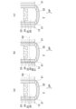
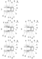
本発明の第5実施形態の副室燃焼4ストロークエンジン1について、図3(a)~図3(c)、図4(a)~図4(e)、図5(a)および図5(b)を用いて説明する。図3(a)~図3(c)は、第5実施形態の3つの例を示す。図4(a)~図4(e)は、第5実施形態の5つの例を示す。図5(a)および図5(b)は、第5実施形態の2つの例を示す。第5実施形態は、第1実施形態~第4実施形態の少なくとも1つの構成を有する。第5実施形態において、副室20の内面は、副室壁部22を含む副室部材25と副室スパークプラグ23とによって形成されている。つまり、副室20の内部空間は、副室部材25と副室スパークプラグ23とによって囲まれた空間である。副室スパークプラグ23の外周面と副室部材25の内周面は接触する。副室部材25は、主燃焼室2の内部空間にその一部が露出するシリンダヘッド本体13と別体で、且つ、副室スパークプラグ23と別体である。シリンダヘッド本体13は、分離不能な1つの部材で構成されていてもよく、主燃焼室2の内部空間にその一部がそれぞれ露出する分離可能な複数の部材で構成されていてもよい。シリンダヘッド本体13が分離可能な複数の部材で構成される場合、シリンダヘッド本体13は、主燃焼室2の内部空間にその一部が露出しない部材は含まない。
Fifth Embodiment
The auxiliary chamber combustion four-
例えば図3(a)および図3(b)に示すように、副室部材25の外周面は、シリンダヘッド本体13に接触していてもよい。例えば図3(b)に示すように、副室部材25に形成された雄ねじ41が、シリンダヘッド本体13に形成された雌ねじ40と噛み合って接触していてもよい。副室部材25の外周面がシリンダヘッド本体13に接触している場合、例えば図3(a)および図3(b)に示すように、副室20の内部空間を通りプラグ軸方向DPに直交するいずれかの平面S2が、副室部材25の外周面のシリンダヘッド本体13に接触する箇所を通ってもよい。接触箇所を通る平面S2は、例えば図3(b)に示すように、副室部材25に形成された雄ねじ41がシリンダヘッド本体13に形成された雌ねじ40と噛み合って接触する箇所を通ってもよい。接触箇所を通る平面S2は、例えば図3(b)に示すように、副室部材25およびシリンダヘッド本体13のねじ部(雄ねじ41と雌ねじ40)ではない箇所を通ってもよい。図3(c)に示す副室部材25の外周面が、図示されていない箇所で、シリンダヘッド本体13に接触していてもよい。例えば、副室スパークプラグ23を通り副室20の内部空間を通らないプラグ軸方向DPに直交するいずれかの平面(図示せず)が、副室部材25の外周面のシリンダヘッド本体13に接触する箇所を通るように、図3(c)に示す副室部材25の外周面がシリンダヘッド本体13に接触していてもよい。この場合、副室部材25の外周面とシリンダヘッド本体13との接触部は、ねじ部(雄ねじ41と雌ねじ40)であってもよく、ねじ部でなくてもよい。
For example, as shown in FIG. 3(a) and FIG. 3(b), the outer peripheral surface of the
副室部材25の外周面は、シリンダヘッド本体13に接触していなくてもよい。例えば図3(c)に示す副室部材25の外周面が、シリンダヘッド本体に接触しなくてもよい。例えば、副室部材25は、シリンダヘッド本体13ではない部材(例えばシリンダヘッドカバー)を介してシリンダヘッド本体に連結されていてもよい。
The outer peripheral surface of the
例えば図4(a)~図4(d)に示すように、冷却部16を通りプラグ軸方向DPに直交するいずれかの平面S3が副室部材25を通るように、副室部材25および冷却部16が形成されていてもよい。平面S3が副室部材25を通る場合、例えば図4(a)~図4(c)に示すように、冷却部16の内面の一部が、副室部材25の外周面の少なくとも一部であってもよい。平面S3が副室部材25を通る場合、例えば図4(d)に示すように、冷却部16の内面が、副室部材25の外周面の一部を含まなくてもよい。また、例えば図4(e)に示すように、冷却部16を通りプラグ軸方向DPに直交するいずれの平面S3も副室部材25を通らないように、副室部材25および冷却部16が形成されていてもよい。なお、図4(a)~図4(d)に示す副室部材25とシリンダヘッド本体13との関係は、図3(a)と同じ関係に限らず、上述したいずれの関係であってもよい。
For example, as shown in FIG. 4(a) to FIG. 4(d), the
冷却部16の内面の一部が副室部材25の外周面の少なくとも一部である場合、例えば図4(b)に示すように、副室部材25は、冷却部16の内部空間に突出する少なくとも1つの放熱部26を有していてもよい。放熱部26は、環状であってもよく、環状でなくてもよい。例えば、放熱部26は、半円より大きい円弧状でもよく、円弧状でなくてもよい。環状の放熱部26は、冷却部16の内部空間を複数の空間に仕切るように形成されていてもよい。副室部材25は、プラグ軸方向DPに並んだ複数の放熱部26を有していてもよい。
When a portion of the inner surface of the
冷却部16を通るいずれかの平面S3が副室部材25を通る場合(例えば図4(a)~図4(d))、冷却部16を通るいずれかの平面S3が、副室部材25の内周面が副室スパークプラグ23の外周面と接触する箇所を通っていてもよい。冷却部16を通るいずれかの平面S3が副室部材25を通る場合、例えば図5(a)および図5(b)に示すように、冷却部16を通るいずれかの平面S3が、副室部材25に形成された雌ねじ42が副室スパークプラグ23に形成された雄ねじ43と噛み合って接触する箇所を通っていてもよい。なお、図5(a)の冷却部16は、図4(a)の冷却部16と同じであるが、図4(b)の冷却部16と同じでもよい。図5(b)の冷却部16は、図4(d)の冷却部16と同じであるが、図4(c)の冷却部16と同じでもよい。なお、図5(a)および図5(b)に示す副室部材25とシリンダヘッド本体13との関係は、図3(a)と同じ関係に限らず、上述したいずれの関係であってもよい。冷却部16を通るいずれかの平面S3が副室部材25を通る場合、冷却部16を通るいずれかの平面S3が、副室部材25の内周面が副室スパークプラグ23の外周面と接触する箇所を通らなくてもよい。
When any plane S3 passing through the
本発明は、上述した実施形態に限られるものではなく、特許請求の範囲に記載した限りにおいて様々な変更が可能である。例えば、本発明の副室燃焼4ストロークエンジンは、スーパーチャージャーまたはターボチャージャーを有してもよい。副室燃焼4ストロークエンジンは、主燃焼室の内部に燃料を噴射する主燃焼室燃料噴射弁を有してもよい。 The present invention is not limited to the above-described embodiment, and various modifications are possible within the scope of the claims. For example, the pre-combustion four-stroke engine of the present invention may have a supercharger or a turbocharger. The pre-combustion four-stroke engine may have a main combustion chamber fuel injection valve that injects fuel into the main combustion chamber.
1:副室燃焼4ストロークエンジン、2:主燃焼室、5:吸気通路、6:排気通路、7:スロットル弁、8:吸気通路噴射弁、10:シリンダヘッド、11:シリンダ孔、13:シリンダヘッド本体、14:副室スパークプラグの電極部から冷却部までの熱経路、15:副室壁部から冷却部までの複数の熱経路、16:冷却部、20:副室、21:連通孔、22:副室壁部、23:副室スパークプラグ、24:電極部、25:副室部材、33:火花放電、40:シリンダヘッド本体の雌ねじ、41:副室部材の雄ねじ、42:副室部材の雌ねじ、43:副室スパークプラグの雄ねじ、70:制御装置、DP:プラグ軸方向、L1:副室の内部空間のプラグ軸方向の長さ、L2:副室の内部空間のプラグ軸方向に直交する方向の最大長さ、S1、S2、S3:平面 1: Pre-chamber combustion four-stroke engine, 2: Main combustion chamber, 5: Intake passage, 6: Exhaust passage, 7: Throttle valve, 8: Intake passage injection valve, 10: Cylinder head, 11: Cylinder bore, 13: Cylinder head body, 14: Heat path from electrode of pre-chamber spark plug to cooling section, 15: Multiple heat paths from pre-chamber wall to cooling section, 16: Cooling section, 20: Pre-chamber, 21: Communication hole, 22: Pre-chamber wall, 23: Pre-chamber spark plug, 24: Electrode section, 25: Pre-chamber member, 33: Spark discharge, 40: Female thread of cylinder head body, 41: Male thread of pre-chamber member, 42: Female thread of pre-chamber member, 43: Male thread of pre-chamber spark plug, 70: Control device, DP: Plug axis direction, L1: Length of the internal space of the pre-chamber in the plug axis direction, L2: Maximum length of the internal space of the pre-chamber in the direction perpendicular to the plug axis direction, S1, S2, S3: Plane
Claims (13)
前記吸気通路を通過して前記主燃焼室に吸入される空気の量を調整するスロットル弁と、
ガソリン燃料、アルコール燃料、またはガソリン・アルコール混合燃料である液体燃料を前記吸気通路の内部に噴射する吸気通路噴射弁と、
前記主燃焼室よりも容積が小さくなるようにシリンダヘッドに形成され、その内部空間が複数の連通孔を介して前記主燃焼室の内部空間と連通し、その内部空間に副室スパークプラグの一部が露出する副室と、
前記吸気通路噴射弁および前記副室スパークプラグを制御する制御装置とを有する副室燃焼4ストロークエンジンであって、
前記制御装置は、前記スロットル弁の開度が小さい低負荷領域の少なくとも一部において、前記吸気通路および前記主燃焼室で混合された混合気が燃焼後に三元触媒で処理できる第1空燃比または前記第1空燃比よりもリッチな第2空燃比となるように、前記吸気通路噴射弁を制御し、
前記副室燃焼4ストロークエンジンは、前記副室に燃料を噴射する副室燃料噴射弁、および、前記副室または前記主燃焼室における混合気の点火を補助する点火補助装置のどちらも有さず、
前記シリンダヘッドは、前記副室スパークプラグの電極部および前記複数の連通孔が形成された副室壁部からの熱を受け取る冷却媒体が収容される冷却部を有し、
前記副室の内部空間が、前記主燃焼室の内部空間にその一部が露出するシリンダヘッド本体および前記副室スパークプラグのどちらとも別体であり、前記複数の連通孔が形成された前記副室壁部を含み、前記副室スパークプラグの外周面と接触する内周面を有する副室部材と、前記副室スパークプラグとによって囲まれた空間であり、
前記電極部に複数の火花放電が周方向に分散して生じるように前記副室スパークプラグの前記電極部が形成され、
前記複数の連通孔が周方向に分散して形成され、
前記副室スパークプラグの前記電極部から前記冷却部までの複数の熱経路、および、前記副室壁部から前記冷却部までの複数の熱経路が、それぞれ周方向に分散して形成されるように前記シリンダヘッドが形成されることを特徴とする副室燃焼4ストロークエンジン。 a main combustion chamber to which an intake passage and an exhaust passage are connected;
a throttle valve for adjusting the amount of air taken into the main combustion chamber through the intake passage;
an intake passage injection valve that injects a liquid fuel, which is gasoline fuel, alcohol fuel, or a gasoline-alcohol mixed fuel, into the intake passage;
a sub-chamber formed in the cylinder head so as to have a smaller volume than the main combustion chamber, the internal space of which communicates with the internal space of the main combustion chamber via a plurality of communication holes, and a portion of the sub-chamber spark plug being exposed in the internal space;
a control device for controlling the intake manifold injection valve and the pre-chamber combustion four-stroke engine,
the control device controls the intake manifold injection valve so that the air-fuel mixture mixed in the intake manifold and the main combustion chamber has a first air-fuel ratio that can be processed by a three-way catalyst after combustion, or a second air-fuel ratio that is richer than the first air-fuel ratio, in at least a part of a low load region where an opening degree of the throttle valve is small;
The pre-chamber combustion four-stroke engine does not have either a pre-chamber fuel injection valve that injects fuel into the pre-chamber, or an ignition assist device that assists in ignition of the mixture in the pre-chamber or the main combustion chamber,
the cylinder head has a cooling portion that accommodates a cooling medium that receives heat from an electrode portion of the sub-chamber spark plug and a sub-chamber wall portion in which the plurality of communication holes are formed,
an internal space of the pre-chamber is a space surrounded by a pre-chamber member that is separate from both a cylinder head body, a part of which is exposed to the internal space of the main combustion chamber, and the pre-chamber spark plug, and that includes the pre-chamber wall portion in which the plurality of communication holes are formed, and that has an inner circumferential surface that contacts an outer circumferential surface of the pre-chamber spark plug, and the pre-chamber spark plug;
The electrode portion of the sub-chamber spark plug is formed so that a plurality of spark discharges are generated in a circumferentially dispersed manner at the electrode portion,
The plurality of communication holes are formed in a circumferentially dispersed manner,
1. A pre-chamber combustion four-stroke engine, comprising: a cylinder head configured such that a plurality of heat paths from the electrode portion of the pre-chamber spark plug to the cooling portion, and a plurality of heat paths from the pre-chamber wall portion to the cooling portion are formed in a circumferentially dispersed manner.
前記副室壁部の外面を通らず前記副室の内部空間を通り前記副室スパークプラグのプラグ軸方向に直交するいずれかの平面によって前記副室の内部空間を2つの空間に分けた場合に、前記2つの空間のうち前記主燃焼室に近い方の空間の体積が、前記2つの空間のうち前記主燃焼室から遠い方の空間の体積よりも小さくなるように前記副室は形成されていることを特徴とする請求項1~3のいずれか1項に記載の副室燃焼4ストロークエンジン。 The auxiliary chamber wall portion is formed so as to protrude into the internal space of the main combustion chamber,
4. The pre-chamber combustion four-stroke engine according to claim 1, wherein the pre-chamber is formed such that, when the internal space of the pre-chamber is divided into two spaces by any plane that passes through the internal space of the pre-chamber without passing through an outer surface of the pre-chamber wall and is perpendicular to a plug axial direction of the pre-chamber spark plug, the volume of the space closer to the main combustion chamber of the two spaces is smaller than the volume of the space farther from the main combustion chamber of the two spaces.
Priority Applications (1)
| Application Number | Priority Date | Filing Date | Title |
|---|---|---|---|
| JP2024024471A JP7686819B2 (en) | 2022-02-15 | 2024-02-21 | Pre-combustion four-stroke engine |
Applications Claiming Priority (3)
| Application Number | Priority Date | Filing Date | Title |
|---|---|---|---|
| JP2022557159A JPWO2023157088A1 (en) | 2022-02-15 | 2022-02-15 | |
| PCT/JP2022/005988 WO2023157088A1 (en) | 2022-02-15 | 2022-02-15 | Pre-chamber combustion four-stroke engine |
| JP2024024471A JP7686819B2 (en) | 2022-02-15 | 2024-02-21 | Pre-combustion four-stroke engine |
Related Parent Applications (1)
| Application Number | Title | Priority Date | Filing Date |
|---|---|---|---|
| JP2022557159A Division JPWO2023157088A1 (en) | 2022-02-15 | 2022-02-15 |
Publications (2)
| Publication Number | Publication Date |
|---|---|
| JP2024056986A JP2024056986A (en) | 2024-04-23 |
| JP7686819B2 true JP7686819B2 (en) | 2025-06-02 |
Family
ID=87565282
Family Applications (2)
| Application Number | Title | Priority Date | Filing Date |
|---|---|---|---|
| JP2022557159A Pending JPWO2023157088A1 (en) | 2022-02-15 | 2022-02-15 | |
| JP2024024471A Active JP7686819B2 (en) | 2022-02-15 | 2024-02-21 | Pre-combustion four-stroke engine |
Family Applications Before (1)
| Application Number | Title | Priority Date | Filing Date |
|---|---|---|---|
| JP2022557159A Pending JPWO2023157088A1 (en) | 2022-02-15 | 2022-02-15 |
Country Status (5)
| Country | Link |
|---|---|
| JP (2) | JPWO2023157088A1 (en) |
| DE (1) | DE112022006634T5 (en) |
| FR (1) | FR3132735B1 (en) |
| TW (1) | TWI828417B (en) |
| WO (1) | WO2023157088A1 (en) |
Citations (2)
| Publication number | Priority date | Publication date | Assignee | Title |
|---|---|---|---|---|
| US20070119409A1 (en) | 2003-05-30 | 2007-05-31 | In Tae Johng | Ignition plugs for internal combustion engine |
| US20170167357A1 (en) | 2015-12-14 | 2017-06-15 | Caterpillar Energy Solutions Gmbh | Prechamber assembly for internal combustion engine |
Family Cites Families (11)
| Publication number | Priority date | Publication date | Assignee | Title |
|---|---|---|---|---|
| JP2594051Y2 (en) * | 1993-08-16 | 1999-04-19 | 株式会社新潟鉄工所 | Cooling type spark plug device |
| US7281527B1 (en) * | 1996-07-17 | 2007-10-16 | Bryant Clyde C | Internal combustion engine and working cycle |
| NO306422B1 (en) * | 1997-04-25 | 1999-11-01 | Leif Dag Henriksen | Internal combustion engine with internal combustion |
| JP2004165168A (en) * | 1999-06-25 | 2004-06-10 | Ngk Spark Plug Co Ltd | Spark plug |
| WO2004040130A1 (en) * | 2002-10-18 | 2004-05-13 | Yamaha Hatsudoki Kabushiki Kaisha | Engine |
| JP4156614B2 (en) * | 2005-06-27 | 2008-09-24 | 日本特殊陶業株式会社 | Internal combustion engine |
| JP2016014340A (en) * | 2014-07-01 | 2016-01-28 | 本田技研工業株式会社 | Internal combustion engine control unit |
| CN106640355A (en) * | 2016-10-19 | 2017-05-10 | 宁波大叶园林设备股份有限公司 | Improved four-stroke engine with overhead camshaft driven by toothed belt and poking plate |
| JP6601423B2 (en) * | 2017-01-11 | 2019-11-06 | トヨタ自動車株式会社 | Exhaust gas purification system for internal combustion engine |
| EP3453856B1 (en) | 2017-09-08 | 2019-10-16 | MASERATI S.p.A. | Gasoline internal combustion engine, with a combustion pre-chamber and two spark plugs |
| WO2020196210A1 (en) * | 2019-03-27 | 2020-10-01 | 三菱自動車工業株式会社 | Auxiliary chamber type internal combustion engine |
-
2022
- 2022-02-15 JP JP2022557159A patent/JPWO2023157088A1/ja active Pending
- 2022-02-15 WO PCT/JP2022/005988 patent/WO2023157088A1/en not_active Ceased
- 2022-02-15 DE DE112022006634.2T patent/DE112022006634T5/en active Pending
- 2022-11-11 TW TW111143166A patent/TWI828417B/en active
-
2023
- 2023-02-14 FR FR2301335A patent/FR3132735B1/en active Active
-
2024
- 2024-02-21 JP JP2024024471A patent/JP7686819B2/en active Active
Patent Citations (2)
| Publication number | Priority date | Publication date | Assignee | Title |
|---|---|---|---|---|
| US20070119409A1 (en) | 2003-05-30 | 2007-05-31 | In Tae Johng | Ignition plugs for internal combustion engine |
| US20170167357A1 (en) | 2015-12-14 | 2017-06-15 | Caterpillar Energy Solutions Gmbh | Prechamber assembly for internal combustion engine |
Also Published As
| Publication number | Publication date |
|---|---|
| JP2024056986A (en) | 2024-04-23 |
| WO2023157088A1 (en) | 2023-08-24 |
| FR3132735A1 (en) | 2023-08-18 |
| DE112022006634T5 (en) | 2025-01-02 |
| TW202334546A (en) | 2023-09-01 |
| FR3132735B1 (en) | 2026-01-16 |
| JPWO2023157088A1 (en) | 2023-08-24 |
| TWI828417B (en) | 2024-01-01 |
Similar Documents
| Publication | Publication Date | Title |
|---|---|---|
| US7438043B2 (en) | Internal combustion engine with auxiliary combustion chamber | |
| EP1402158B1 (en) | Improved cylinder assembly for an aircraft engine | |
| IT9021997A1 (en) | IMPROVED COMBUSTION SYSTEM FOR TWO FUEL ENGINES | |
| CN110168825A (en) | Spark plug with shuttle electrode | |
| EP3460929B1 (en) | Spark plug for an internal combustion engine | |
| JP7686819B2 (en) | Pre-combustion four-stroke engine | |
| US4098246A (en) | Internal combustion engine with an auxiliary combustion chamber | |
| US4216748A (en) | Internal combustion engine with subsidiary combustion chamber | |
| WO2023283061A1 (en) | Cylinder head assembly and cylinder head having igniter cooling moat | |
| EP1749997B1 (en) | Fuel injection type internal combustion engine | |
| WO2023157382A1 (en) | Pre-chamber-combustion four-stroke engine | |
| JP7426511B2 (en) | Pre-chamber combustion 4-stroke engine | |
| CN100532791C (en) | Internal combustion engine with spark plug and vehicle provided with the internal combustion engine | |
| US5313921A (en) | High efficiency combustion chamber system | |
| WO2022049839A1 (en) | Two-stroke engine | |
| JP4461948B2 (en) | Hydrogenated internal combustion engine | |
| JPH11182249A (en) | Direct injection spark ignition type internal combustion engine | |
| JP2020139442A (en) | Cylinder head with auxiliary combustion chamber | |
| WO2023021531A1 (en) | Pre-chamber ignition unit for an internal combustion engine | |
| JP4345714B2 (en) | In-cylinder direct injection layer combustion engine | |
| JPWO2023157382A5 (en) | ||
| JP2007113534A (en) | Sub-chamber internal combustion engine | |
| KR800000435B1 (en) | Reduction device of NOx, HC and CO in exhaust gas of internal combustion engine | |
| JP2010048137A (en) | Internal combustion engine | |
| JP2007273421A (en) | Spark plug |
Legal Events
| Date | Code | Title | Description |
|---|---|---|---|
| A621 | Written request for application examination |
Free format text: JAPANESE INTERMEDIATE CODE: A621 Effective date: 20240221 |
|
| TRDD | Decision of grant or rejection written | ||
| A01 | Written decision to grant a patent or to grant a registration (utility model) |
Free format text: JAPANESE INTERMEDIATE CODE: A01 Effective date: 20250430 |
|
| A61 | First payment of annual fees (during grant procedure) |
Free format text: JAPANESE INTERMEDIATE CODE: A61 Effective date: 20250521 |
|
| R150 | Certificate of patent or registration of utility model |
Ref document number: 7686819 Country of ref document: JP Free format text: JAPANESE INTERMEDIATE CODE: R150 |