JP7686814B2 - Imaging device and control method thereof - Google Patents
Imaging device and control method thereof Download PDFInfo
- Publication number
- JP7686814B2 JP7686814B2 JP2024017483A JP2024017483A JP7686814B2 JP 7686814 B2 JP7686814 B2 JP 7686814B2 JP 2024017483 A JP2024017483 A JP 2024017483A JP 2024017483 A JP2024017483 A JP 2024017483A JP 7686814 B2 JP7686814 B2 JP 7686814B2
- Authority
- JP
- Japan
- Prior art keywords
- focus
- subject
- detection
- history
- detection means
- Prior art date
- Legal status (The legal status is an assumption and is not a legal conclusion. Google has not performed a legal analysis and makes no representation as to the accuracy of the status listed.)
- Active
Links
Images


Landscapes
- Focusing (AREA)
- Automatic Focus Adjustment (AREA)
- Studio Devices (AREA)
Description
本発明は焦点調節機構を持つ撮像装置に関するものである。 The present invention relates to an imaging device with a focus adjustment mechanism.
従来から、デジタルカメラなどの撮像装置は利用者の利便性のために自動焦点調節(以下AF)機能を備えている。また、近年は画像解析により顔を検知する機能を備えている機種が一般的である。そして動く物体や人をAF追従するために、AFさせるフォーカス位置を過去の履歴から予測する動体予測制御を備える機種もある。 Traditionally, imaging devices such as digital cameras have been equipped with an automatic focus adjustment (AF) function for the convenience of the user. In recent years, models equipped with a function to detect faces through image analysis have become common. Some models also have motion prediction control that predicts the AF focus position from past history in order to track moving objects or people with AF.
このような機種で、たとえば遠くから近づいてくる人を撮影する場合、最初は被写体が小さく顔検知が働かないため、胴体領域にAFしたとする。徐々に近づいてくるため先ほどの動体予測も働かせながらAFを行う。その後、さらに近づいてくると、画像の中での人の面積が増え、顔検知が働く。一般的に顔にピントがあった写真が求められるため、AF対象とする領域を、胴体から顔に乗り移らせる。 With this type of camera, for example, when photographing a person approaching from a distance, the subject is initially small and face detection does not work, so AF is focused on the torso area. As the person gradually approaches, AF is performed while also using the motion prediction mentioned earlier. As the person then approaches even closer, the area of the person in the image increases and face detection is activated. Since a photo with the face in focus is generally desired, the area targeted by AF is shifted from the torso to the face.
しかしながら、AF対象を胴体から顔に乗り移らせた場合、胴体に比べて顔は小さい被写体であるため、AFに位相差検知方式を用いると、顔と背景との遠近競合が起き、焦点検出結果が顔より後ろ寄りとなる場合があった。この場合、せっかく胴体でピントが合っていたのに、顔に乗り移ったとたんに後ピンとなり、顔にピントが合わないことになる。 However, when the AF target is shifted from the torso to the face, since the face is a smaller subject compared to the torso, if phase difference detection is used for AF, perspective conflict occurs between the face and the background, and the focus detection result may be behind the face. In this case, even though the focus was set on the torso, as soon as the focus shifts to the face, it becomes back focus and the face is not in focus.
さらに動体予測を行っていた場合には、実際には人が一定の速度で近づいているにもかかわらず、焦点検出結果としては急に反転し、次の動体予測結果はさらに後ピンになる。このように過応答の動作になって、さらにひどいピンボケとなる場合があった。 Furthermore, when motion prediction was being performed, even if a person was actually approaching at a constant speed, the focus detection result would suddenly reverse, and the next motion prediction result would be even further back in focus. This resulted in over-responsive operation, which could result in even more severe out-of-focus images.
特許文献1ではその対策として、信頼性で乗り移り判断を行う方法を挙げている。しかし信頼性で遠近競合を高い精度で検知するのは難しい。利用者の要求としても顔にAFしたいところである。
As a countermeasure,
本発明の技術的特徴として、撮影光学系を通過した光束から撮像信号を取得する撮像素子と、前記撮像素子からの出力により得られた画像から被写体を検知する第1の検知手段と、前記撮像素子からの出力により得られた画像から前記被写体の一部分を検知する第2の検知手段と、前記被写体及び前記被写体の一部分の焦点状態を検出する焦点検出手段と、前記焦点検出手段により検出された被写体及び被写体の一部分の焦点検出結果の履歴を保存する履歴手段と、を有する撮像装置であって、前記焦点検出手段により、前記第1の検知手段により検知された被写体の焦点状態を検出している際に、前記履歴手段に保存された前記第1の検知手段により検知された被写体の焦点検出結果の分散が一定以上である場合、前記第1の検知手段により検知された被写体にピント合わせを行い、前記履歴手段に保存された前記第1の検知手段により検知された被写体の焦点検出結果の分散が一定以上でない場合、前記第2の検知手段により検知された被写体の一部分にピント合わせを行う。 A technical feature of the present invention is an imaging device having an imaging element which acquires an imaging signal from a light beam which has passed through an imaging optical system, a first detection means which detects a subject from an image obtained by output from the imaging element, a second detection means which detects a part of the subject from the image obtained by output from the imaging element, a focus detection means which detects a focus state of the subject and the part of the subject, and a history means which stores a history of focus detection results of the subject and the part of the subject detected by the focus detection means, wherein when the focus detection means detects the focus state of the subject detected by the first detection means, if the variance of the focus detection results of the subject detected by the first detection means stored in the history means is equal to or greater than a certain level, focusing is performed on the subject detected by the first detection means, and if the variance of the focus detection results of the subject detected by the first detection means stored in the history means is not equal to or greater than a certain level, focusing is performed on the part of the subject detected by the second detection means.
本発明に依れば、安定したピント追従をすることができる。 This invention allows for stable focus tracking.
以下に、本発明の好ましい実施の形態を、添付の図面に基づいて詳細に説明する。 A preferred embodiment of the present invention will be described in detail below with reference to the accompanying drawings.
(第1の実施形態)(顔の大きさで胴から顔へ乗り移り判断し、履歴をリセット)
<撮像装置の構成>
本実施形態では、レンズユニットと撮像装置が着脱可能となったレンズ交換式の撮像装置において、本発明を適用した場合の例を示す。
(First embodiment) (judging whether the robot has moved from the body to the face based on the size of the face, and resetting the history)
<Configuration of Imaging Device>
In this embodiment, an example in which the present invention is applied to an image pickup apparatus of an interchangeable lens type in which the lens unit and the image pickup apparatus are detachable will be described.
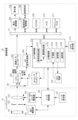
図1は、撮像装置の主要部の構成を示すブロック図である。 Figure 1 is a block diagram showing the configuration of the main parts of the imaging device.
図1に示すように、交換可能なレンズユニット10に着脱可能な撮像装置20は、レンズユニット10を含めたカメラシステム全体の動作を統括するカメラ制御部212を中心に構成される。撮像装置の制御は、カメラ制御部212の内部のROM、RAM(不図示)に格納された制御プログラム及び制御に必要な各種データに基づき実行される。
As shown in FIG. 1, the
また、レンズユニット10は、レンズ全体の動作を統括制御するレンズ制御部106を有し、レンズ制御部106と、カメラ制御部212とは、レンズマウントに設けられた端子を通じて相互に通信可能である。
The
まず、レンズユニット10の構成について説明する。固定レンズ101、絞り102、フォーカスレンズ103は撮影光学系を構成する。絞り102は、絞り駆動部104によって駆動され、後述する撮像素子201への入射光量を制御する。フォーカスレンズ103はフォーカスレンズ駆動部105によって駆動され、フォーカスレンズ103の位置に応じて撮像光学系の合焦距離が変化する。絞り駆動部104、フォーカスレンズ駆動部105はレンズ制御部106によって制御され、絞り102の開口量や、フォーカスレンズ103の位置を決定する。
First, the configuration of the
レンズ操作部107は、AF/MFモードの切り替え、MFによるフォーカスレンズの位置調整、フォーカスレンズの動作範囲設定、手ブレ補正モードの設定など、ユーザがレンズユニット10の動作に関する設定を行うための入力デバイス群である。レンズ操作部107が操作された場合、レンズ制御部106が操作に応じた制御を行う。
The
レンズ制御部106は、後述するカメラ制御部212から受信した制御命令や制御情報に応じて絞り駆動部104やフォーカスレンズ駆動部105を制御し、また、レンズ制御情報をカメラ制御部212に送信する。
The
次に、撮像装置20の構成について説明する。撮像装置20はレンズユニット10の撮影光学系を通過した光束から撮像信号を取得できるように構成されている。
Next, the configuration of the
撮像素子201はCCDやCMOSセンサにより構成される。レンズユニット10の撮影光学系から入射した光束は撮像素子201の受光面上に結像し、撮像素子201に配列された画素に設けられたフォトダイオードにより、入射光量に応じた信号電荷に変換される。各フォトダイオードに蓄積された信号電荷は、カメラ制御部212の指令に従ってタイミングジェネレータ214が出力する駆動パルスより、信号電荷に応じた電圧信号として撮像素子201から順次読み出される。
The
本実施形態で用いられる撮像素子201の各画素は、2つ(一対)のフォトダイオードA、Bとこれら一対のフォトダイオードA、Bに対して設けられた1つのマイクロレンズとより構成されている。各画素は、入射する光をマイクロレンズで分割して一対のフォトダイオードA、B上に一対の光学像を形成し、該一対のフォトダイオードA、Bから後述するAF用信号に用いられる一対の画素信号(A信号およびB信号)を出力する。また、一対のフォトダイオードA、Bの出力を加算することで、撮像用信号(A+B信号)を得ることができる。
Each pixel of the
複数の画素から出力された複数のA信号はA信号同士、複数のB信号はB信号同士でそれぞれ合成する。これにより、撮像面位相差検出方式によるAF(以下、撮像面位相差AFという)に用いられるAF用信号(言い換えれば、焦点検出用信号)としての一対の像信号が得られる。後述するAF信号処理部204は、該一対の像信号に対する相関演算を行って、これら一対の像信号のずれ量である位相差(以下、像ずれ量という)を算出し、さらに該像ずれ量から撮影光学系のデフォーカス量(およびデフォーカス方向)を算出する。このデフォーカス量とデフォーカス方向は焦点検出結果であり、焦点状態を示す。
The multiple A signals output from the multiple pixels are combined with each other, and the multiple B signals are combined with each other. This results in a pair of image signals as AF signals (in other words, focus detection signals) used for AF using an image plane phase difference detection method (hereinafter referred to as image plane phase difference AF). The AF
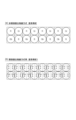
図2(a)には撮像面位相差AFに対応していない画素構成を、図2(b)は撮像面位相差AFに対応した画素構成を示している。いずれの図においても、ベイヤー配列が用いられており、Rは赤のカラーフィルタを、Bは青のカラーフィルタを、Gr、Gbは緑のカラーフィルタを示している。撮像面位相差AFに対応する図2(b)に示す画素構成では、図2(a)に示した撮像面位相差AFに非対応の画素構成における1画素(実線で囲んで示す)に相当する画素内に、図の水平方向に2分割された2つのフォトダイオードA、Bが設けられている。なお、図2(b)に示した画素の分割方法は例に過ぎず、図の垂直方向に分割したり、水平および垂直方向に2分割ずつ(計4分割)したりしてもよい。また、同じ撮像素子内において互いに異なる分割方法で分割された複数種類の画素が含まれてもよい。 2(a) shows a pixel configuration that does not support image plane phase difference AF, and FIG. 2(b) shows a pixel configuration that supports image plane phase difference AF. In both figures, a Bayer array is used, with R representing a red color filter, B representing a blue color filter, and Gr and Gb representing green color filters. In the pixel configuration shown in FIG. 2(b) that supports image plane phase difference AF, two photodiodes A and B that are divided into two in the horizontal direction of the figure are provided in a pixel that corresponds to one pixel (shown surrounded by a solid line) in the pixel configuration that does not support image plane phase difference AF shown in FIG. 2(a). Note that the pixel division method shown in FIG. 2(b) is merely an example, and the pixel may be divided in the vertical direction of the figure, or divided into two each in the horizontal and vertical directions (a total of four divisions). In addition, the same image sensor may include multiple types of pixels divided by different division methods.
CDS/AGC/ADコンバータ202は、撮像素子201から読み出されたAF用信号および撮像用信号に対して、リセットノイズを除去するための相関二重サンプリング、ゲイン調節およびAD変換を行う。該コンバータ202は、これらの処理を行った撮像用信号およびAF用信号をそれぞれ、画像入力コントローラ203およびAF信号処理部204に出力する。
The CDS/AGC/
画像入力コントローラ203は、コンバータ202から出力された撮像用信号をバス21を介してSDRAM209に画像信号として格納する。SDRAM209に格納された画像信号は、バス21を介して表示制御部205によって読み出され、表示部206に表示される。また、画像信号の記録を行う録画モードでは、SDRAM209に格納された画像信号は記録媒体制御部207によって半導体メモリ等の記録媒体208に記録される。
The
ROM210には、カメラ制御部212が実行する制御プログラムや処理プログラムおよびこれらの実行に必要な各種データ等が格納されている。フラッシュROM211には、ユーザにより設定されたカメラ20の動作に関する各種設定情報等が格納されている。
The
カメラ制御部212内の被写体検出部2121は、画像入力コントローラ203から入力された撮像用信号を基に特定の被写体を検出して、撮像用信号内での特定の被写体の位置を決定する。また、画像入力コントローラ203から連続的に撮像信号を入力し、検出した特定の被写体が移動した場合には移動先の位置を判断し、特定の被写体の位置を追従する。特定の被写体とは、例えば人被写体や、動物、自動車などの乗り物、カメラ操作部213でユーザによって撮像画面内で指定された位置に存在する被写体などが一例である。更に器官検出部2122は、被写体検出部2121で検出された被写体において、人の顔や、乗り物に乗っている人の顔などを検出して、撮像用信号内での特定の位置を決定する。後述するように、検出した特定の被写体の位置や大きさに関する情報は、主にAFを行う領域の設定の為に用いる。
The
焦点検出装置としてのAF信号処理部204は、コンバータ202から出力されたAF用信号である一対の像信号に対して相関演算を行い、これら一対の像信号の像ずれ量や信頼性を算出する。信頼性は、後述する二像一致度と相関変化量の急峻度を用いて算出される。また、AF信号処理部204は、撮像画面内で焦点検出およびAFを行う領域である焦点検出領域の位置および大きさの設定を行う。AF信号処理部204は、焦点検出領域で算出した像ずれ量(検出量)および信頼性の情報をカメラ制御部212に出力する。なお、AF信号処理部204が行う処理の詳細については後述する。
The AF
カメラ制御部212内のAF制御部2123は、換算したデフォーカス量に基づいて焦点位置を移動させるようにレンズ制御部106に指示を行う。さらにAF制御部2123は、将来の像面位置を予測部2124を用いて予測し、フォーカスレンズ103が予測した像面位置に来るために必要なレンズ駆動量を算出し、レンズ制御部106に指示を行う。
The
記憶部2125は、撮影時刻とでフォーカス量から算出した被写体像面位置をメモリ回路215に記憶させる。
The
選択部2126は、予測部2124によって算出された、被写体検出部2121によって検出された人領域のデフォーカス量に基づく像面速度と、器官検出部2122によって検出された顔領域のデフォーカス量に基づく像面速度との比較をする。そして、被写体検出部2121と器官検出部2122のどちらの像面予測位置に向けてフォーカスレンズを駆動するかを選択する。
The
カメラ制御部212は、撮像装置20内の各部と情報をやり取りしながらこれらを制御する。また、カメラ制御部212は、ユーザ操作に基づくカメラ操作部213からの入力に応じて、電源のON/OFF、各種設定の変更、撮像処理、AF処理、記録画像の再生処理等、ユーザ操作に対応する様々な処理を実行する。さらに、カメラ制御部212は、レンズユニット10(レンズ制御部106)に対する制御命令や撮像装置20の情報をレンズ制御部106に送信したり、レンズユニット10の情報をレンズ制御部106から取得したりする。カメラ制御部212は、マイクロコンピュータにより構成され、ROM210に記憶されたコンピュータプログラムを実行することで、交換レンズ10を含むカメラシステム全体の制御を司る。
The
カメラ制御部212は、AF信号処理部204にて算出された焦点検出領域での像ずれ量を用いてデフォーカス量を算出し、該デフォーカス量に基づいてレンズ制御部106を通じてフォーカスレンズ103の駆動を制御する。
The
<焦点調節動作の手順>
以下、撮像装置20で行われる処理について説明する。カメラ制御部212は、コンピュータプログラムである撮像処理プログラムに従って以下の処理を行う。
<Focus adjustment procedure>
The following describes the processing performed by the
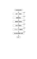
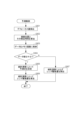
図3は撮像装置20の撮影処理、特にAF制御部2123で行われる焦点調節動作の手順を示すフローチャートである。Sはステップを意味する。
Figure 3 is a flowchart showing the steps of the photographing process of the
初めに、カメラ制御部212は、カメラ設定やカメラ操作部213からの入力に応じて焦点調節動作を実行するかを判断する(S301)。
First, the
焦点調節動作を実行すると判断すると、S302において、焦点検出処理を行う。なお、焦点検出処理の詳細については、図4を用いて後述する。 If it is determined that a focus adjustment operation is to be performed, focus detection processing is performed in S302. Details of the focus detection processing will be described later with reference to FIG. 4.
S303では、撮影前予測処理を行う。撮影前予測処理では、後述するように撮影開始スイッチがオン状態であれば、S302の焦点検出処理における位相差検出時から撮像素子201による撮影時までの被写体の像面位置を予測部2124によって予測する。また、撮影開始スイッチがオフ状態であれば、次の位相差検出時までの被写体の像面位置を予測部2124によって予測する。なお、予測方法の詳細については図9を用いて後述する。
In S303, a pre-shooting prediction process is performed. In the pre-shooting prediction process, if the shooting start switch is in the on state as described below, the
S304では、S303で算出された像面速度を用いて、被写体検出部2121によって検出された人領域の像面位置と、器官検出部2122によって検出された顔領域の像面位置の、どちらに合焦するようにフォーカスレンズ103を動かすかを選択する。なお、選択方法の詳細については図10を用いて後述する。
In S304, the image plane velocity calculated in S303 is used to select whether to move the
S305で、S303で予測し、S304で選択した被写体像面位置に合焦するように、フォーカスレンズ103を動かすために必要なレンズ駆動量を算出し、レンズ制御部106に伝える。
In S305, the lens drive amount required to move the
次にS306で、撮影開始スイッチの状態を判定し、スイッチオン状態であれば、S307の撮影に移行して、スイッチオフ状態であればS310に移行する。 Next, in S306, the state of the shooting start switch is determined, and if the switch is on, the process proceeds to shooting in S307, and if the switch is off, the process proceeds to S310.
S307で、撮像素子201により撮影された画像をメモリ回路215に記憶する。S308において、次の位相差検出時の被写体の像面位置を予測部2124によって予測し、S309で、S308で予測した像面位置に合焦するようにフォーカスレンズ103を動かすために必要なレンズ駆動量を算出し、レンズ制御部106に伝える。
In S307, the image captured by the
S310で撮影準備スイッチオフ判定を行い、スイッチオフ状態であれば処理を終了し、スイッチオン状態であればS302に戻って、上記処理を繰り返す。 In S310, it is determined whether the shooting preparation switch is off. If the switch is off, the process ends. If the switch is on, the process returns to S302 and the above process is repeated.
<焦点検出処理>
図4のフローチャートで、S302で行われる焦点検出処理の動作の一例を説明する。
<Focus Detection Processing>
An example of the operation of the focus detection process performed in S302 will be described with reference to the flowchart in FIG.
初めに、AF信号処理部204は、撮像素子201における焦点検出領域に含まれる複数の画素からAF用信号としての一対の像信号を取得する(S401)。図5(a)は、撮像素子201の画素アレイ501上での焦点検出領域502の例を示している。焦点検出領域502の両側のシフト領域503は、相関演算に必要な領域である。このため、焦点検出領域502とシフト領域503とを合わせた領域504が相関演算に必要な画素領域である。図中のp、q、s、tはそれぞれ、水平方向(x軸方向)での座標を表し、pとqはそれぞれ画素領域504の始点と終点のx座標を、sとtはそれぞれ焦点検出領域502の始点と終点のx座標を示している。また、図6は、図5(a)に示した焦点検出領域502に含まれる複数の画素から取得したAF用の一対の像信号の例を示している。実線601が一方の像信号Aであり、破線602が他方の像信号Bである。図6(a)はシフト前の像信号A、Bを示し、図6(b)、(c)はそれぞれ、像信号A、Bを図6(a)の状態からプラス方向およびマイナス方向にシフトした状態を示している。
First, the AF
次に、AF信号処理部204は、取得した一対の像信号を1画素(1ビット)ずつ相対的にシフトさせながらこれら一対の像信号の相関量を算出する(S402)。焦点検出領域内に設けた複数の画素ライン(以下、走査ラインという)のそれぞれにおいて、図6(b)、(c)のように像信号A601、B602の両方を矢印の方向に1ビットずつシフトしていく。これにより一対の像信号A601、B602の相関量を算出し、それぞれの相関量を加算平均することで1つの相関量として算出する。ここでは、相関量算出にあたって一対の像信号を1画素ずつ相対的にシフトさせる構成としたが、たとえば2画素ずつ相対的にシフトさせる等、より多くの画素単位でシフトさせる構成でも構わない。また、各走査ラインの相関量を加算平均することで1つの相関量を算出したが、たとえば各走査ラインの一対の像信号に対して加算平均を行い、その後、加算平均した一対の像信号に対して相関量の算出を行う構成でも構わない。シフト量をiとし、最小シフト量をp-sとし、最大シフト量をq-tとし、xを焦点検出領域502の開始座標とし、yを焦点検出領域502の終了座標とするとき、相関量CORは以下の式(1)によって算出することができる。
Next, the AF

図7(a)に、シフト量と相関量CORとの関係の例を示す。横軸はシフト量、縦軸は相関量CORである。シフト量とともに変化する相関量701における極値付近702、703のうち、より小さい相関量に対応するシフト量において一対の像信号A、Bの一致度が最も高くなる。
Figure 7(a) shows an example of the relationship between the shift amount and the correlation amount COR. The horizontal axis is the shift amount, and the vertical axis is the correlation amount COR. Among the
続いて、AF信号処理部204は、S402で算出した相関量から相関変化量を算出する(S403)。図7(a)に示した相関量701の波形における1シフトおきの相関量の差を相関変化量として算出し、シフト量をi、最小シフト量をp-s、最大シフト量をq-tとすると、相関変化量ΔCORは以下の式(2)によって算出することができる。
Then, the AF

次に、AF信号処理部204は、S403で算出した相関変化量を用いて像ずれ量を算出する(S404)。図8(a)は、シフト量と相関変化量ΔCORとの関係の例を示しており、横軸はシフト量、縦軸は相関変化量ΔCORを表している。シフト量とともに変化する相関変化量801は、802、803の部分でプラスからマイナスになる。相関変化量が0となる状態をゼロクロスと呼び、一対の像信号A、Bの一致度が最も高くなる。したがって、ゼロクロスを与えるシフト量が像ずれ量となる。図8(b)に図8(a)中の802で示した部分を拡大して示す。804は相関変化量801の一部分である。ゼロクロスを与えるシフト量(k-1+α)は、整数部分β(=k-1)と小数部分αとに分けられる。小数部分αは、図中の三角形ABCと三角形ADEとの相似の関係から、以下の式(3)によって算出することができる。
Next, the AF

また整数部分βは、図8(b)から以下の式(4)によって算出することができる。
(式4)
β=k-1 (4)
Moreover, the integer part β can be calculated from FIG. 8B using the following formula (4).
(Formula 4)
β=k−1 (4)
すなわち、αとβの和から像ずれ量PRDを算出することができる。図8(a)に示したように相関変化量ΔCORのゼロクロスが複数存在する場合は、その付近での相関変化量ΔCORの変化の急峻性がより大きい方を第1のゼロクロスとする。この急峻性はAFの行い易さを示す指標であり、値が大きいほど精度良いAFを行い易い点であることを示す。急峻性maxderは、以下の式(5)によって算出することができる。 That is, the image shift amount PRD can be calculated from the sum of α and β. When there are multiple zero crossings of the correlation change amount ΔCOR as shown in FIG. 8(a), the first zero crossing is the one in the vicinity of which the steepness of the change in the correlation change amount ΔCOR is greater. This steepness is an index showing the ease of performing AF, and the larger the value, the easier it is to perform accurate AF. The steepness maxder can be calculated using the following formula (5).
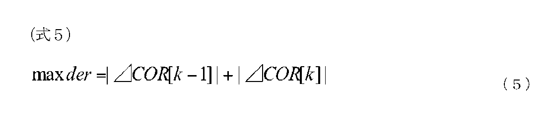
本実施形態では、相関変化量のゼロクロスが複数存在する場合は、その急峻性によって第1のゼロクロスを決定し、この第1のゼロクロスを与えるシフト量を像ずれ量とする。 In this embodiment, when there are multiple zero crossings in the correlation change amount, the first zero crossing is determined based on its steepness, and the shift amount that gives this first zero crossing is taken as the image shift amount.
次に、AF信号処理部204は、S404で算出された焦点検出領域の像ずれ量を用いて該焦点検出領域のデフォーカス量を算出する(S405)。そして、S406において、得られた焦点検出情報をメモリ回路215に記憶する。ここでは、各焦点検出領域のデフォーカス量と、像信号A、像信号Bの撮影時刻、像面速度を記憶する。
Next, the AF
<撮影前予測>
図9を用いて、S303で予測部2124により行われる、過去複数回の像面位置とその撮影時刻の変化から、将来の像面位置を予測するための撮影前予測について説明する。
<Pre-shooting predictions>
The pre-imaging prediction performed by the
まず、S901において、被写体検出部2121で検出された領域において、AF信号処理部204によって検出した位相差からデフォーカス量を算出する。そして、次のS902にて、算出したデフォーカス量に対応する像面位置とその撮影時刻の算出を行う。一般的に、撮像素子201から像信号が得られるまでにある程度の電荷の蓄積時間を必要とする。そのため、蓄積開始時刻と終了時刻の中点を撮影時刻として、フォーカスレンズ103の相対的な繰り出し量にこのデフォーカス量を加えることによって、被写体の像面位置を算出する。そして、像面位置と撮影時刻の組のデータを、次のS903にてメモリ回路215に格納する。格納するメモリのデータ構造はキューとなっており、予め定められたデータの個数までは順に格納するがそれ以降のデータは、最も古いデータの上に最新のデータを上書きする。その後、S904へ進み、メモリ回路215に格納されたデータ数が統計演算可能かどうかを判定する。この判定の結果、統計演算に必要なデータ数が十分であればS905へ進み、統計演算による予測式を決定する。S905における統計演算による予測式の決定は、式(6)に示すような予測関数f(t)において、重回帰分析によって各係数α、β、γを統計的に決定する。また、式(6)におけるnは複数の代表的な動体予測撮影シーンのサンプルに対して予測を行ったとき、その予測誤差が最小となるnの値を求めている。
(式6)
f(t)=α+βt+γtn (6)
First, in S901, the defocus amount is calculated from the phase difference detected by the AF
(Formula 6)
f(t)=α+βt+γtn (6)
S905で予測式を決定した後はS906に進み、予め決められた将来時刻の像面位置を予測し、フォーカスレンズ103がその像面位置に合焦するために必要なレンズ駆動量を算出する。一方、S904においてデータ数が十分でないと判定した場合、S907に進み、統計演算によらず算出したデフォーカス量によってレンズ駆動量を算出する。上記処理を器官検出部2122で検出された領域においても行う。
After the prediction formula is determined in S905, the process proceeds to S906, where the image plane position at a predetermined future time is predicted, and the lens drive amount required for the
<合焦する領域の選択処理の必要性、概要>
図11を用いて、S304で行われる選択処理の必要性、概要について説明する。
<Outline of the necessity for selection of the area to be focused>
The necessity for and overview of the selection process performed in S304 will be described with reference to FIG.
図11(a)1101が被写体の人物を表している。この人物にピントを合わせるときに、図5(a)の焦点検出領域502に相当するものが、1111と1112である。
In Figure 11(a), 1101 represents the subject, a person. When focusing on this person, 1111 and 1112 correspond to the
基本的に人物写真は顔にピントを合わせるべきである。顔と体では距離が違う場合があり、また同じ距離であっても空間周波数やコントラストの違いにより焦点検出結果が変わることがある。そこで1111は顔を認識して顔の座標にピントを合わせようとしているが、顔検出の精度や被写体の動きなどによりぴったり顔に合うとは限らない。1111のように顔からはみ出していると、背景の画像に相関量を引っ張られ、デフォーカスが後ろ寄りになる、遠近競合という状態になる。このとき1112のように人物の胴体にピントをと、顔より胴体の方が大きいので、顔と胴体の距離の差はあるものの、遠近競合はおきにくく、より正確なピント合わせが可能になる。 In portraits, the focus should generally be on the face. The distance between the face and the body may differ, and even if the distance is the same, differences in spatial frequency and contrast may affect the focus detection results. Therefore, 1111 attempts to recognize the face and focus on the coordinates of the face, but it does not always focus exactly on the face due to factors such as the accuracy of face detection and the movement of the subject. If the focus extends beyond the face as in 1111, the correlation amount will be pulled by the background image, causing the defocus to move backwards, a state known as perspective conflict. In this case, if the focus is on the person's torso as in 1112, and the torso is larger than the face, perspective conflict is unlikely to occur despite the difference in distance between the face and torso, and more accurate focusing is possible.
図11(b)(c)(d)はそれぞれ人物にピントを合わせる様子を表している。(b)、(c)、(d)の順に被写体がカメラに向かって近づいてきている。図11(e)はその時の顔と胴体のデフォーカス量を示す。図11(b)の1121が顔の焦点検出領域を表しそのデフォーカス量をdef1bとする。図11(b)の1122が胴の焦点検出領域を表しそのデフォーカス量をdef2bとする。図11(c)の1131が顔の焦点検出領域を表しそのデフォーカス量をdef1cとする。図11(c)の1132が胴の焦点検出領域を表しそのデフォーカス量をdef2cとする。図11(d)の1141が顔の焦点検出領域を表しそのデフォーカス量をdef1dとする。図11(d)の1142が胴の焦点検出領域を表しそのデフォーカス量をdef2dとする。先の例のようにすべて顔にピントとしたら、def1b、def1c、def1dを順に採用することになる。しかし先の通りdef1bの焦点検出領域は顔をはみ出しているので遠近競合している可能性がある。 Figures 11(b), (c), and (d) each show how a person is brought into focus. The subject approaches the camera in the order of (b), (c), and (d). Figure 11(e) shows the defocus amount of the face and torso at that time. 1121 in Figure 11(b) represents the focus detection area of the face, and its defocus amount is def1b. 1122 in Figure 11(b) represents the focus detection area of the torso, and its defocus amount is def2b. 1131 in Figure 11(c) represents the focus detection area of the face, and its defocus amount is def1c. 1132 in Figure 11(c) represents the focus detection area of the torso, and its defocus amount is def2c. 1141 in Figure 11(d) represents the focus detection area of the face, and its defocus amount is def1d. In Figure 11(d), 1142 represents the focus detection area for the torso, and its defocus amount is def2d. If the focus is to be entirely on the face as in the previous example, def1b, def1c, and def1d would be adopted in that order. However, as mentioned above, the focus detection area for def1b extends beyond the face, so there is a possibility of perspective conflict.
胴体にピントを合わせるとしたらdef2b、def2c、def2dを順に採用することになる。その場合は先の通り遠近競合は起きにくいものの図11(d)位の距離になると顔と胴体の距離差が無視できない量になる。そこで、所定の条件として被写体の顔の大きさを見て、def2b、def2c→def1dと途中で胴体から顔に乗り移る制御が考えられる。 If you want to focus on the torso, you would use def2b, def2c, and def2d in that order. In that case, perspective conflict is unlikely to occur as mentioned above, but at a distance of about Figure 11(d), the difference in distance between the face and the torso becomes significant. Therefore, one possible control would be to look at the size of the subject's face as a specified condition, and shift from the torso to the face along the way, going from def2b, def2c, to def1d.
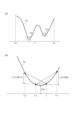
図11(f)が図11(d)の各デフォーカスをグラフにプロットしたものである。縦軸がデフォーカス量を表し、横軸が時間を表す。被写体は徐々に近づいてきており点線1151で示す。またここでは各顔のデフォーカスは少しずつ遠近競合している例を表している。
Figure 11(f) is a graph plotting each of the defocuses in Figure 11(d). The vertical axis represents the amount of defocus, and the horizontal axis represents time. The subject gradually gets closer, as indicated by the dotted
ここで先のように被写体の顔の大きさを見て、def2b、def2c→def1dと途中で胴体から顔に乗り移る制御を行う場合で、def1dも被写体の動きなどにより遠近競合していたとする。すると、図9で説明した通りデフォーカスの予測制御を行っており、近づく動きに急ブレーキがかかったように測定され、1152の曲線を予測することになる。もしずっと一定量遠近競合していたとして、予測制御を行わなかったとすると1162くらいの誤差で済んでいたところを、予測制御によって1161の位置を予測してしまい、予測を行わない焦点検出結果より、さらにピントを大外しすることになる。そこで仮に(d)の時点で胴体から顔に乗り移る際には、(b)(c)の過去の像面位置と撮影時刻のデータを消去すれば、過去の履歴を無くすことによって過応答と呼ばれる現象の頻度を押さえることができる。 Now, as mentioned above, when the size of the subject's face is checked and control is performed to switch from the body to the face in the middle, from def2b, def2c to def1d, and def1d also has perspective conflict due to the movement of the subject. Then, as explained in FIG. 9, predictive control of defocus is performed, and it is measured as if the approaching movement was suddenly braked, and the curve of 1152 is predicted. If there had been a constant amount of perspective conflict all along and predictive control had not been performed, the error would have been about 1162, but predictive control predicts the position of 1161, resulting in an even greater deviation from the focus than the focus detection result without prediction. Therefore, if the focus transitions from the body to the face at point (d), by erasing the data of the past image plane positions and shooting times of (b) and (c), the frequency of the phenomenon called hyper-response can be suppressed by eliminating past history.
<合焦する領域の選択処理>
図10を用いて、S304で行われる選択処理の具体的なフローを説明する。
<Selection of Area to Be Focused>
A specific flow of the selection process performed in S304 will be described with reference to FIG.
S1001で器官検出部2122によって検出された顔の大きさを取得する。S1002で顔の大きさが一定以上か判定する。一定以下であればAFを行う被写体は被写体検出領域のままS1003へ、一定以上であれば顔検出領域に移す(S1004)。S1003では被写体検出領域の像面位置へフォーカスレンズ駆動することを選択し、処理を終了する。S1004では顔検出領域の像面位置へフォーカスレンズを駆動することを選択する。S1005で、前回選択した領域は被写体検出領域であり、今回はS1004で顔検出領域を選択し、結果として体全体/胴体から顔に乗り移ったのであればS1006へ、そうでなければ処理を終了する。S1006では、S903でメモリ回路215に格納した、過去の像面位置と撮影時刻の組のデータを消去して、処理を終了する。
In S1001, the size of the face detected by the
なお、ここでは本発明の好ましい実施形態について説明したが、本発明はこれらの実施形態に限定されず、その要旨の範囲内で種々の変形及び変更が可能である。 Although the preferred embodiments of the present invention have been described here, the present invention is not limited to these embodiments, and various modifications and variations are possible within the scope of the gist of the invention.
以上のように、本発明の第1の実施形態によれば、被写体検出領域で検出する人全体/胴体から顔検出領域へ乗り移る際に、顔の大きさを見て小さい顔に乗り移りにくくすることによって、小さい顔と背景による遠近競合の頻度を減らすことができる。 As described above, according to the first embodiment of the present invention, when switching from the entire person/torso detected in the subject detection area to the face detection area, the frequency of perspective conflicts between a small face and the background can be reduced by checking the size of the face and making it less likely to switch to a small face.
また、被写体検出領域で検出する人全体/胴体から顔検出領域へ乗り移ったあとに、過去の像面位置と撮影時刻のデータの履歴を消去することによって、乗り移った後の過応答の頻度を減らすことができる。 In addition, after switching from the entire person/torso detected in the subject detection area to the face detection area, the frequency of over-responses after switching can be reduced by deleting the history of data on past image plane positions and shooting times.
(第2の実施形態)(履歴の分散/急加減速から胴から顔への乗り移り判定)
以下説明するシーケンス、処理フローを除いては、第1の実施形態と同一の構成・制御を行うものとする。
(Second embodiment) (Dispersion of history/Determination of transfer from torso to face due to sudden acceleration/deceleration)
Except for the sequences and processing flows described below, the configuration and control are the same as those in the first embodiment.
前述の説明では、図10を用いて、S304で行われる選択処理の具体的なフローを説明した。このときS1002で顔の大きさが一定以上か判定した。しかしながら、これを過去の履歴、たとえば所定の条件として、図11(e)のdef2b,def2c,def2d・・・の分散が大きいようであれば、今不規則な運動をしている最中なので予測や頭部への乗り移りに適当でないと判断してもよい。 In the above explanation, the specific flow of the selection process performed in S304 was explained using Figure 10. At this time, in S1002, it was determined whether the face size was a certain size or larger. However, if this is taken as a past history, for example as a predetermined condition, and the variance of def2b, def2c, def2d, etc. in Figure 11(e) is large, it may be determined that the robot is currently performing irregular movements and is therefore not suitable for prediction or transfer onto the head.
また所定の条件として、図11(e)のdef2b,def2c,def2d・・・の後の方、最新の状態で急加速、急減速しているように判断できる場合も同様に、予測や頭部への乗り移りに適当でないと判断してもよい。 As a predetermined condition, if it is determined that the most recent state is suddenly accelerating or decelerating after def2b, def2c, def2d, etc. in FIG. 11(e), it may be determined that the state is not suitable for prediction or transfer to the head.
また、def2b,def2c,def2d・・・という胴体のデフォーカス履歴から以上の分散や急加減速を判断したが、履歴の最後を頭部に乗り移り後のデフォーカスを加えて判断してもよい。具体的には、def2b、def2c、def1dとなる。 The above dispersion and sudden acceleration/deceleration were determined from the defocus history of the torso, def2b, def2c, def2d, etc., but it is also possible to determine this by adding the defocus after the transfer to the head at the end of the history. Specifically, it would be def2b, def2c, def1d.
以上のように、本発明の第2の実施形態によれば、被写体検出領域で検出する人全体/胴体から顔検出領域へ乗り移る際に、過去の履歴を見て顔に乗り移るか判断することによって、小さい顔と背景による遠近競合の頻度を減らすことができる。 As described above, according to the second embodiment of the present invention, when moving from the entire person/torso detected in the subject detection area to the face detection area, the frequency of perspective conflicts between a small face and the background can be reduced by checking past history to determine whether to move onto a face.
(第3の実施形態)(乗り移り後DEFMAP履歴をさかのぼり顔位置の狭領域で予測)
以下説明するシーケンス、処理フローを除いては、第1の実施形態または第2の実施形態と同一の構成・制御を行うものとする。
(Third embodiment) (Predicting a narrow region of face position by tracing back DEFMAP history after transfer)
Except for the sequences and processing flows described below, the configuration and control are the same as those of the first or second embodiment.
図12を用いて、第3の実施形態のS304で行われる選択処理の必要性、概要について説明する。 The necessity for and overview of the selection process performed in S304 in the third embodiment will be explained using Figure 12.
図11(a)で1111,1112の2枠の焦点検出領域について例を示した。本実施形態では図12(a)のように方眼状に複数の焦点検出領域を持つものとする。1つ1つはそれぞれ焦点検出領域502を表すものとする。そして図中31個の焦点検出領域について、S903で各焦点検出領域のデフォーカス情報と時刻を同時に保存するものとする。さらに図5(a)の焦点検出領域502を狭くした、図5(b)の焦点検出領域502による、狭領域のデフォーカス情報を持ってもよい。横方向に狭くすることによって遠近競合しにくくなるが、代わりに大デフォーカス能力が落ちる。図12(b)が上記31個の焦点検出領域のそれぞれのデフォーカス情報を標準の焦点検出領域と狭領域の焦点検出領域のそれぞれ、過去の履歴のデフォーカス情報を持った例である。1201の位置が焦点検出領域1、1202の位置が顔の中心である焦点検出領域16、1203の位置が胴体の中心である焦点検出領域29にあたる。
Figure 11(a) shows an example of two focus detection areas, 1111 and 1112. In this embodiment, as shown in Figure 12(a), there are multiple focus detection areas in a grid pattern. Each one represents a
この状態で図10のS304で行われる選択処理を行う。被写体がカメラに向かって接近している場合で、まだ顔が小さいときS1003が選択された場合は、胴体の標準の焦点検出領域のデフォーカス履歴を使って予測を行う。点線1212の焦点検出領域29の標準の焦点検出領域の履歴を使う。被写体が近づいて顔の大きさが大きくなったときS1004が選択された場合は、顔の狭領域の焦点検出領域のデフォーカス履歴を使って予測を行う。点線1211の焦点検出領域16の狭領域の焦点検出領域の履歴を使う。この場合S1006の履歴情報のクリアは行わない。
In this state, the selection process of S304 in FIG. 10 is performed. If S1003 is selected when the subject is approaching the camera and the face is still small, a prediction is made using the defocus history of the standard focus detection area of the torso. The history of the standard focus detection area of focus detection area 29 of dotted
本実施形態では過去の履歴のメモリ保存量は増えるが、S1006のように過去の履歴のクリアを行わず、過去にさかのぼって顔の場所のデフォーカス履歴を用い、かつ、顔のような小さい被写体向けの狭枠のデフォーカス情報を用いる。これにより遠近競合が起こりにくい。 In this embodiment, the amount of memory storage for past history increases, but instead of clearing the past history as in S1006, the defocus history for the face location is used going back in time, and narrow-frame defocus information for small subjects such as faces is used. This makes it less likely that perspective conflicts will occur.
以上のように、第3の実施形態によれば、被写体検出領域で検出する人全体/胴体から顔検出領域へ乗り移ったあとに、過去にさかのぼって顔の場所のデフォーカス履歴を用いる。また、顔のような小さい被写体向けの狭領域の焦点検出領域のデフォーカス情報を用いる。このため、遠近競合の頻度を減らすことができる。 As described above, according to the third embodiment, after switching from the entire person/torso detected in the subject detection area to the face detection area, the defocus history of the face location is used going back in time. In addition, defocus information from a narrow focus detection area for small subjects such as a face is used. This makes it possible to reduce the frequency of perspective conflicts.
(その他の実施形態)
本発明は、上述の実施例の1以上の機能を実現するプログラムを、ネットワーク又は記憶媒体を介してシステム又は装置に供給し、そのシステム又は装置のコンピュータにおける1つ以上のプロセッサーがプログラムを読出し実行する処理でも実現可能である。また、1以上の機能を実現する回路(例えば、ASIC)によっても実現可能である。
Other Embodiments
The present invention can also be realized by a process in which a program for implementing one or more of the functions of the above-described embodiments is supplied to a system or device via a network or a storage medium, and one or more processors in a computer of the system or device read and execute the program. The present invention can also be realized by a circuit (e.g., ASIC) that implements one or more of the functions.
また、上述した各実施形態においては、本発明をデジタルカメラに適用した場合を例にして説明したが、これはこの例に限定されない。すなわち、本発明は、撮像素子が付随したあらゆるデバイスに適用してもよい。すなわち携帯電話端末や携帯型の画像ビューワ、カメラを備えるテレビ、デジタルフォトフレーム、音楽プレーヤー、ゲーム機、電子ブックリーダーなど、画像を撮像可能な装置であれば、本発明は適用可能である。 In addition, in each of the above-mentioned embodiments, the present invention has been described as being applied to a digital camera, but this is not limited to this example. In other words, the present invention may be applied to any device that is equipped with an image sensor. In other words, the present invention can be applied to any device that can capture images, such as a mobile phone terminal, a portable image viewer, a television equipped with a camera, a digital photo frame, a music player, a game console, or an e-book reader.
また、上述の実施例では、レンズ鏡筒と撮像装置が一体となったレンズ鏡筒括りつけの撮像装置を説明したが、レンズ交換式の撮像装置であってもよい。レンズ交換式の撮像装置は、交換可能なレンズユニット(レンズ鏡筒)とカメラ本体(撮像装置)とを備えて構成される。レンズユニット全体の動作を統括制御するレンズ制御部と、レンズユニットを含めたカメラシステム全体の動作を統括するカメラ制御部とは、レンズマウントに設けられた端子を通じて相互に通信可能な構成とする。 In the above embodiment, an imaging device with a lens barrel attached, in which the lens barrel and the imaging device are integrated, has been described, but an imaging device with interchangeable lenses may also be used. An imaging device with interchangeable lenses is configured with an interchangeable lens unit (lens barrel) and a camera body (imaging device). A lens control unit that controls the overall operation of the lens unit and a camera control unit that controls the overall operation of the camera system including the lens unit are configured to be able to communicate with each other through terminals provided on the lens mount.
10 レンズユニット
103 フォーカスレンズ
105 フォーカスレンズ駆動部
106 レンズ制御部
20 撮像装置
201 撮像素子
204 AF信号処理部
205 表示制御部
206 表示部
207 記録媒体制御部
208 記録媒体
212 カメラ制御部
2121 被写体検出部
2122 器官検出部
2123 AF制御部
213 カメラ操作部
REFERENCE SIGNS
Claims (8)
前記撮像素子からの出力により得られた画像から被写体を検知する第1の検知手段と、
前記撮像素子からの出力により得られた画像から前記被写体の一部分を検知する第2の検知手段と、
前記被写体及び前記被写体の一部分の焦点状態を検出する焦点検出手段と、
前記焦点検出手段により検出された被写体及び被写体の一部分の焦点検出結果の履歴を保存する履歴手段と、を有する撮像装置であって、
前記焦点検出手段により、前記第1の検知手段により検知された被写体の焦点状態を検出している際に、前記履歴手段に保存された前記第1の検知手段により検知された被写体の焦点検出結果の分散が一定以上である場合、前記第1の検知手段により検知された被写体にピント合わせを行い、前記履歴手段に保存された前記第1の検知手段により検知された被写体の焦点検出結果の分散が一定以上でない場合、前記第2の検知手段により検知された被写体の一部分にピント合わせを行うことを特徴とする撮像装置。 an image sensor for acquiring an image signal from a light beam that has passed through an image capturing optical system;
a first detection means for detecting a subject from an image obtained by output from the image sensor;
a second detection means for detecting a portion of the subject from an image obtained by outputting the image sensor;
a focus detection means for detecting a focus state of the subject and a part of the subject;
a history unit for storing a history of focus detection results of the object and a part of the object detected by the focus detection unit,
an imaging device characterized in that, when the focus detection means detects the focus state of the subject detected by the first detection means, if the variance of the focus detection results of the subject detected by the first detection means stored in the history means is equal to or greater than a certain level, the imaging device adjusts the focus on the subject detected by the first detection means, and if the variance of the focus detection results of the subject detected by the first detection means stored in the history means is not equal to or greater than a certain level, the imaging device adjusts the focus on a part of the subject detected by the second detection means.
前記撮像素子からの出力により得られた画像から被写体を検知する第1の検知手段と、
前記撮像素子からの出力により得られた画像から前記被写体の一部分を検知する第2の検知手段と、
前記被写体及び前記被写体の一部分の焦点状態を検出する焦点検出手段と、
前記焦点検出手段により検出された被写体及び被写体の一部分の焦点検出結果の履歴を保存する履歴手段と、を有する撮像装置であって、
前記焦点検出手段により、前記第1の検知手段により検知された被写体の焦点状態を検出している際に、前記履歴手段に保存された前記第1の検知手段により検知された被写体の焦点検出結果から前記第1の検知手段により検知された被写体が急加速していると判定された場合、又は、前記第1の検知手段により検知された被写体が急減速していると判定された場合、前記第1の検知手段により検知された被写体にピント合わせを行い、前記履歴手段に保存された前記第1の検知手段により検知された被写体の焦点検出結果から前記第1の検知手段により検知された被写体が急加速も急減速もしていないと判定された場合、前記第2の検知手段により検知された被写体の一部分にピント合わせを行うことを特徴とする撮像装置。 an image sensor for acquiring an image signal from a light beam that has passed through an image capturing optical system;
a first detection means for detecting a subject from an image obtained by output from the image sensor;
a second detection means for detecting a portion of the subject from an image obtained by outputting the image sensor;
a focus detection means for detecting a focus state of the subject and a part of the subject;
a history unit for storing a history of focus detection results of the object and a part of the object detected by the focus detection unit,
an image pickup device characterized in that, when the focus detection means detects a focus state of the subject detected by the first detection means, if it is determined from the focus detection result of the subject detected by the first detection means stored in the history means that the subject detected by the first detection means is accelerating rapidly or if it is determined from the focus detection result of the subject detected by the first detection means that the subject detected by the first detection means is decelerating rapidly, the image pickup device focuses on the subject detected by the first detection means, and if it is determined from the focus detection result of the subject detected by the first detection means stored in the history means that the subject detected by the first detection means is not accelerating or decelerating rapidly, the image pickup device focuses on a part of the subject detected by the second detection means.
前記撮像素子からの出力により得られた画像から被写体を検知する第1の検知工程と、
前記撮像素子からの出力により得られた画像から前記被写体の一部分を検知する第2の検知工程と、
前記被写体及び前記被写体の一部分の焦点状態を検出する焦点検出工程と、
前記焦点検出工程により検出された被写体及び被写体の一部分の焦点検出結果の履歴を保存する履歴工程と、
前記焦点検出工程により、前記第1の検知工程により検知された被写体の焦点状態を検出している際に、前記履歴工程において保存された前記第1の検知工程により検知された被写体の焦点検出結果の分散が一定以上である場合、前記第1の検知工程により検知された被写体にピント合わせを行い、前記履歴工程において保存された前記第1の検知工程により検知された被写体の焦点検出結果の分散が一定以上でない場合、前記第2の検知工程により検知された被写体の一部分にピント合わせを行うピント合わせ工程と、を有することを特徴とする撮像装置の制御方法。 A method for controlling an imaging device having an imaging element that acquires an imaging signal from a light beam that has passed through an imaging optical system, comprising the steps of:
a first detection step of detecting a subject from an image obtained by output from the image sensor;
a second detection step of detecting a portion of the subject from an image obtained by output from the image sensor;
a focus detection step of detecting a focus state of the object and a part of the object;
a history step for storing a history of focus detection results of the object and a part of the object detected by the focus detection step;
a focusing step of, when a focus state of the subject detected by the first detection step is detected by the focus detection step, focusing on the subject detected by the first detection step if a variance of the focus detection results of the subject detected by the first detection step stored in the history step is equal to or greater than a certain level, and focusing on a portion of the subject detected by the second detection step if the variance of the focus detection results of the subject detected by the first detection step stored in the history step is not equal to or greater than a certain level.
前記撮像素子からの出力により得られた画像から被写体を検知する第1の検知工程と、
前記撮像素子からの出力により得られた画像から前記被写体の一部分を検知する第2の検知工程と、
前記被写体及び前記被写体の一部分の焦点状態を検出する焦点検出工程と、
前記焦点検出工程により検出された被写体及び被写体の一部分の焦点検出結果の履歴を保存する履歴工程と、
前記焦点検出工程により、前記第1の検知工程により検知された被写体の焦点状態を検出している際に、前記履歴工程において保存された前記第1の検知工程により検知された被写体の焦点検出結果から前記第1の検知工程により検知された被写体が急加速していると判定された場合、又は、前記第1の検知工程により検知された被写体が急減速していると判定された場合、前記第1の検知工程により検知された被写体にピント合わせを行い、前記履歴工程において保存された前記第1の検知工程により検知された被写体の焦点検出結果から前記第1の検知工程により検知された被写体が急加速も急減速もしていないと判定された場合、前記第2の検知工程により検知された被写体の一部分にピント合わせを行うピント合わせ工程と、を有することを特徴とする撮像装置の制御方法。 A method for controlling an imaging device having an imaging element that acquires an imaging signal from a light beam that has passed through an imaging optical system, comprising the steps of:
a first detection step of detecting a subject from an image obtained by output from the image sensor;
a second detection step of detecting a portion of the subject from an image obtained by output from the image sensor;
a focus detection step of detecting a focus state of the object and a part of the object;
a history step for storing a history of focus detection results of the object and a part of the object detected by the focus detection step;
a focusing step of adjusting the focus on the subject detected by the first detection step when it is determined from the focus detection result of the subject detected by the first detection step stored in the history step that the subject detected by the first detection step is rapidly accelerating or rapidly decelerating, while detecting a focus state of the subject detected by the first detection step by the focus detection step, and adjusting the focus on a portion of the subject detected by the second detection step when it is determined from the focus detection result of the subject detected by the first detection step stored in the history step that the subject detected by the first detection step is not rapidly accelerating or decelerating.
Priority Applications (1)
| Application Number | Priority Date | Filing Date | Title |
|---|---|---|---|
| JP2024017483A JP7686814B2 (en) | 2019-11-29 | 2024-02-07 | Imaging device and control method thereof |
Applications Claiming Priority (2)
| Application Number | Priority Date | Filing Date | Title |
|---|---|---|---|
| JP2019217569A JP7438732B2 (en) | 2019-11-29 | 2019-11-29 | Imaging device and its control method |
| JP2024017483A JP7686814B2 (en) | 2019-11-29 | 2024-02-07 | Imaging device and control method thereof |
Related Parent Applications (1)
| Application Number | Title | Priority Date | Filing Date |
|---|---|---|---|
| JP2019217569A Division JP7438732B2 (en) | 2019-11-29 | 2019-11-29 | Imaging device and its control method |
Publications (2)
| Publication Number | Publication Date |
|---|---|
| JP2024045467A JP2024045467A (en) | 2024-04-02 |
| JP7686814B2 true JP7686814B2 (en) | 2025-06-02 |
Family
ID=76087639
Family Applications (2)
| Application Number | Title | Priority Date | Filing Date |
|---|---|---|---|
| JP2019217569A Active JP7438732B2 (en) | 2019-11-29 | 2019-11-29 | Imaging device and its control method |
| JP2024017483A Active JP7686814B2 (en) | 2019-11-29 | 2024-02-07 | Imaging device and control method thereof |
Family Applications Before (1)
| Application Number | Title | Priority Date | Filing Date |
|---|---|---|---|
| JP2019217569A Active JP7438732B2 (en) | 2019-11-29 | 2019-11-29 | Imaging device and its control method |
Country Status (1)
| Country | Link |
|---|---|
| JP (2) | JP7438732B2 (en) |
Families Citing this family (1)
| Publication number | Priority date | Publication date | Assignee | Title |
|---|---|---|---|---|
| JP7720895B2 (en) * | 2023-11-16 | 2025-08-08 | キヤノン株式会社 | Focus adjustment device and method, imaging device, program, and storage medium |
Citations (9)
| Publication number | Priority date | Publication date | Assignee | Title |
|---|---|---|---|---|
| JP2007286255A (en) | 2006-04-14 | 2007-11-01 | Nikon Corp | camera |
| JP2010072559A (en) | 2008-09-22 | 2010-04-02 | Nikon Corp | Imaging apparatus and object area extracting method |
| JP2010186004A (en) | 2009-02-12 | 2010-08-26 | Sony Corp | Imaging apparatus, method for controlling the same, and program |
| JP2013219615A (en) | 2012-04-10 | 2013-10-24 | Canon Inc | Imaging apparatus and method for controlling the same |
| JP2016057421A (en) | 2014-09-09 | 2016-04-21 | キヤノン株式会社 | Focus adjustment device and focus adjustment method |
| JP2016142924A (en) | 2015-02-02 | 2016-08-08 | キヤノン株式会社 | Imaging apparatus, control method therefor, program, and storage medium |
| JP2017223751A (en) | 2016-06-14 | 2017-12-21 | キヤノン株式会社 | Focus adjustment device |
| JP2018197845A (en) | 2017-05-24 | 2018-12-13 | キヤノン株式会社 | Focus control device and imaging device |
| JP2019101320A (en) | 2017-12-06 | 2019-06-24 | キヤノン株式会社 | Focus adjustment apparatus, control method thereof, program and imaging apparatus |
Family Cites Families (1)
| Publication number | Priority date | Publication date | Assignee | Title |
|---|---|---|---|---|
| JP3891224B2 (en) * | 1995-12-07 | 2007-03-14 | 株式会社ニコン | Automatic focusing device |
-
2019
- 2019-11-29 JP JP2019217569A patent/JP7438732B2/en active Active
-
2024
- 2024-02-07 JP JP2024017483A patent/JP7686814B2/en active Active
Patent Citations (9)
| Publication number | Priority date | Publication date | Assignee | Title |
|---|---|---|---|---|
| JP2007286255A (en) | 2006-04-14 | 2007-11-01 | Nikon Corp | camera |
| JP2010072559A (en) | 2008-09-22 | 2010-04-02 | Nikon Corp | Imaging apparatus and object area extracting method |
| JP2010186004A (en) | 2009-02-12 | 2010-08-26 | Sony Corp | Imaging apparatus, method for controlling the same, and program |
| JP2013219615A (en) | 2012-04-10 | 2013-10-24 | Canon Inc | Imaging apparatus and method for controlling the same |
| JP2016057421A (en) | 2014-09-09 | 2016-04-21 | キヤノン株式会社 | Focus adjustment device and focus adjustment method |
| JP2016142924A (en) | 2015-02-02 | 2016-08-08 | キヤノン株式会社 | Imaging apparatus, control method therefor, program, and storage medium |
| JP2017223751A (en) | 2016-06-14 | 2017-12-21 | キヤノン株式会社 | Focus adjustment device |
| JP2018197845A (en) | 2017-05-24 | 2018-12-13 | キヤノン株式会社 | Focus control device and imaging device |
| JP2019101320A (en) | 2017-12-06 | 2019-06-24 | キヤノン株式会社 | Focus adjustment apparatus, control method thereof, program and imaging apparatus |
Also Published As
| Publication number | Publication date |
|---|---|
| JP2024045467A (en) | 2024-04-02 |
| JP7438732B2 (en) | 2024-02-27 |
| JP2021086137A (en) | 2021-06-03 |
Similar Documents
| Publication | Publication Date | Title |
|---|---|---|
| US7826735B2 (en) | Auto focus unit and digital camera | |
| US9681037B2 (en) | Imaging apparatus and its control method and program | |
| JP7596476B2 (en) | Focus detection device, imaging device, and focus detection method | |
| JP5618712B2 (en) | Automatic focusing device and imaging device | |
| US10542202B2 (en) | Control apparatus that performs focusing by imaging-plane phase difference AF, image capturing apparatus, control method, and non-transitory computer-readable storage medium | |
| JP4823167B2 (en) | Imaging device | |
| US20200228719A1 (en) | Focus control apparatus, imaging apparatus, focus control method, and storage medium | |
| US12395732B2 (en) | Focusing apparatus, image pickup apparatus, focusing method, and storage medium, which can provide stable focusing | |
| US10326925B2 (en) | Control apparatus for performing focus detection, image capturing apparatus, control method, and non-transitory computer-readable storage medium | |
| JP7686814B2 (en) | Imaging device and control method thereof | |
| JP7066388B2 (en) | Focus control device, its control method, and program, storage medium, and image pickup device. | |
| JP2012133041A (en) | Imaging apparatus, lens system and control method thereof | |
| JP7532067B2 (en) | Focus detection device, imaging device, and focus detection method | |
| JP2009042555A (en) | Electronic camera | |
| US20190320122A1 (en) | Control apparatus, image capturing apparatus, control method, and non-transitory computer-readable storage medium | |
| JP7719849B2 (en) | Focus control device, lens device, and imaging device | |
| JP7421008B2 (en) | Imaging device, imaging method, and program | |
| JP5207893B2 (en) | Imaging apparatus and control method thereof | |
| JP5973784B2 (en) | Imaging apparatus, control method therefor, program, and storage medium | |
| JP2014029429A (en) | Imaging device, control method, and program | |
| JP2010113130A (en) | Focus detecting device, imaging apparatus, focus detecting method | |
| JP2009042556A (en) | Electronic camera | |
| JP2018197771A (en) | Control device, imaging apparatus, control method, program, and storage medium | |
| JP2012242759A (en) | Imaging apparatus, control method therefor, and program | |
| JP7321691B2 (en) | IMAGING DEVICE, IMAGING DEVICE CONTROL METHOD, AND PROGRAM |
Legal Events
| Date | Code | Title | Description |
|---|---|---|---|
| A621 | Written request for application examination |
Free format text: JAPANESE INTERMEDIATE CODE: A621 Effective date: 20240214 |
|
| A977 | Report on retrieval |
Free format text: JAPANESE INTERMEDIATE CODE: A971007 Effective date: 20241016 |
|
| A131 | Notification of reasons for refusal |
Free format text: JAPANESE INTERMEDIATE CODE: A131 Effective date: 20241112 |
|
| A521 | Request for written amendment filed |
Free format text: JAPANESE INTERMEDIATE CODE: A523 Effective date: 20241206 |
|
| A131 | Notification of reasons for refusal |
Free format text: JAPANESE INTERMEDIATE CODE: A131 Effective date: 20250212 |
|
| A521 | Request for written amendment filed |
Free format text: JAPANESE INTERMEDIATE CODE: A523 Effective date: 20250409 |
|
| TRDD | Decision of grant or rejection written | ||
| A01 | Written decision to grant a patent or to grant a registration (utility model) |
Free format text: JAPANESE INTERMEDIATE CODE: A01 Effective date: 20250422 |
|
| A61 | First payment of annual fees (during grant procedure) |
Free format text: JAPANESE INTERMEDIATE CODE: A61 Effective date: 20250521 |
|
| R150 | Certificate of patent or registration of utility model |
Ref document number: 7686814 Country of ref document: JP Free format text: JAPANESE INTERMEDIATE CODE: R150 |