JP7686811B2 - Temperature Dependent Switch - Google Patents
Temperature Dependent Switch Download PDFInfo
- Publication number
- JP7686811B2 JP7686811B2 JP2024009302A JP2024009302A JP7686811B2 JP 7686811 B2 JP7686811 B2 JP 7686811B2 JP 2024009302 A JP2024009302 A JP 2024009302A JP 2024009302 A JP2024009302 A JP 2024009302A JP 7686811 B2 JP7686811 B2 JP 7686811B2
- Authority
- JP
- Japan
- Prior art keywords
- temperature
- switching mechanism
- external terminal
- switch
- dependent
- Prior art date
- Legal status (The legal status is an assumption and is not a legal conclusion. Google has not performed a legal analysis and makes no representation as to the accuracy of the status listed.)
- Active
Links
Images

Classifications
-
- H—ELECTRICITY
- H01—ELECTRIC ELEMENTS
- H01H—ELECTRIC SWITCHES; RELAYS; SELECTORS; EMERGENCY PROTECTIVE DEVICES
- H01H37/00—Thermally-actuated switches
- H01H37/02—Details
-
- H—ELECTRICITY
- H01—ELECTRIC ELEMENTS
- H01H—ELECTRIC SWITCHES; RELAYS; SELECTORS; EMERGENCY PROTECTIVE DEVICES
- H01H37/00—Thermally-actuated switches
- H01H37/02—Details
- H01H37/32—Thermally-sensitive members
- H01H37/52—Thermally-sensitive members actuated due to deflection of bimetallic element
- H01H37/54—Thermally-sensitive members actuated due to deflection of bimetallic element wherein the bimetallic element is inherently snap acting
- H01H37/5418—Thermally-sensitive members actuated due to deflection of bimetallic element wherein the bimetallic element is inherently snap acting using cantilevered bimetallic snap elements
-
- H—ELECTRICITY
- H01—ELECTRIC ELEMENTS
- H01H—ELECTRIC SWITCHES; RELAYS; SELECTORS; EMERGENCY PROTECTIVE DEVICES
- H01H1/00—Contacts
- H01H1/50—Means for increasing contact pressure, preventing vibration of contacts, holding contacts together after engagement, or biasing contacts to the open position
- H01H1/504—Means for increasing contact pressure, preventing vibration of contacts, holding contacts together after engagement, or biasing contacts to the open position by thermal means
-
- H—ELECTRICITY
- H01—ELECTRIC ELEMENTS
- H01H—ELECTRIC SWITCHES; RELAYS; SELECTORS; EMERGENCY PROTECTIVE DEVICES
- H01H1/00—Contacts
- H01H1/58—Electric connections to or between contacts; Terminals
-
- H—ELECTRICITY
- H01—ELECTRIC ELEMENTS
- H01H—ELECTRIC SWITCHES; RELAYS; SELECTORS; EMERGENCY PROTECTIVE DEVICES
- H01H3/00—Mechanisms for operating contacts
- H01H3/60—Mechanical arrangements for preventing or damping vibration or shock
-
- H—ELECTRICITY
- H01—ELECTRIC ELEMENTS
- H01H—ELECTRIC SWITCHES; RELAYS; SELECTORS; EMERGENCY PROTECTIVE DEVICES
- H01H37/00—Thermally-actuated switches
- H01H37/02—Details
- H01H37/04—Bases; Housings; Mountings
-
- H—ELECTRICITY
- H01—ELECTRIC ELEMENTS
- H01H—ELECTRIC SWITCHES; RELAYS; SELECTORS; EMERGENCY PROTECTIVE DEVICES
- H01H37/00—Thermally-actuated switches
- H01H37/02—Details
- H01H37/32—Thermally-sensitive members
- H01H37/52—Thermally-sensitive members actuated due to deflection of bimetallic element
- H01H37/54—Thermally-sensitive members actuated due to deflection of bimetallic element wherein the bimetallic element is inherently snap acting
- H01H37/5427—Thermally-sensitive members actuated due to deflection of bimetallic element wherein the bimetallic element is inherently snap acting encapsulated in sealed miniaturised housing
-
- H—ELECTRICITY
- H01—ELECTRIC ELEMENTS
- H01H—ELECTRIC SWITCHES; RELAYS; SELECTORS; EMERGENCY PROTECTIVE DEVICES
- H01H37/00—Thermally-actuated switches
- H01H37/02—Details
- H01H37/32—Thermally-sensitive members
- H01H37/52—Thermally-sensitive members actuated due to deflection of bimetallic element
- H01H37/54—Thermally-sensitive members actuated due to deflection of bimetallic element wherein the bimetallic element is inherently snap acting
- H01H2037/5463—Thermally-sensitive members actuated due to deflection of bimetallic element wherein the bimetallic element is inherently snap acting the bimetallic snap element forming part of switched circuit
Landscapes
- Physics & Mathematics (AREA)
- Thermal Sciences (AREA)
- Electromagnetism (AREA)
- Thermally Actuated Switches (AREA)
Description
本発明は、温度依存型スイッチに関する。 The present invention relates to a temperature-dependent switch.
複数の温度依存型スイッチが、原則として既に知られている。温度依存型スイッチの例は、ドイツ特許公開公報197 52 581号に開示されている。温度依存型スイッチの別の例は、ドイツ特許公開公報198 07 288号に開示されている。 Several temperature-dependent switches are already known in principle. An example of a temperature-dependent switch is disclosed in DE-OS 197 52 581. Another example of a temperature-dependent switch is disclosed in DE-OS 198 07 288.
この種の温度依存型スイッチは、デバイスの温度を監視するために、それ自体既知の方法で使用される。この目的のために、スイッチは、例えばその外面のうちの1つによって保護されるデバイスと熱接触させられ、その結果、保護されるデバイスの温度は、スイッチの内側に配置されるスイッチング機構の温度に影響を及ぼす。 Temperature-dependent switches of this kind are used in a manner known per se to monitor the temperature of a device. For this purpose, the switch is brought into thermal contact with the device to be protected, for example by one of its outer surfaces, so that the temperature of the protected device affects the temperature of the switching mechanism arranged inside the switch.
その外部の電気的接続を用いて、スイッチは、ケーブルを接続することによって保護されるデバイスの供給回路に直列に電気的に接続され、その結果、スイッチの応答温度以下では、保護されるデバイスの供給電流がスイッチを通る。 With its external electrical connection, the switch is electrically connected in series with the supply circuit of the protected device by connecting a cable so that below the response temperature of the switch, the supply current of the protected device passes through the switch.
スイッチに設置された温度依存型のスイッチング機構は、スイッチの温度依存型のスイッチング挙動を保証する。この温度依存型のスイッチング機構は、通常、2つの電極の間に配置され、電極は、次に各2つの外部端子のうちの1つに電気的に接続される。温度依存型のスイッチング機構は、スイッチの応答温度またはスイッチング機構の応答温度以下では、閉塞位置にあって、スイッチング機構はスイッチの2つの外部の電気的接続間に導電性接続を確立し、スイッチの応答温度を超えると、スイッチング機構は開放位置に切り換えられて、スイッチの2つの外部の電気的接続間の導電性接続が切り離されるか、遮断されるように構成されている。 A temperature-dependent switching mechanism installed in the switch ensures the temperature-dependent switching behavior of the switch. This temperature-dependent switching mechanism is usually arranged between two electrodes which are in turn electrically connected to one of the two external terminals. The temperature-dependent switching mechanism is configured such that at or below the response temperature of the switch, the switching mechanism is in a closed position, where the switching mechanism establishes a conductive connection between the two external electrical connections of the switch, and above the response temperature of the switch, the switching mechanism is switched to an open position, where the conductive connection between the two external electrical connections of the switch is disconnected or interrupted.
このように、温度依存型のスイッチング機構は、スイッチの応答温度を下回るその閉塞位置において、保護すべきデバイスの供給回路を閉鎖し、かつ、スイッチの応答温度を上回っているその開放位置において、保護すべきデバイスの供給回路を遮断することを確実にする。これは、そのような温度依存型スイッチを用いて、望ましくない過熱の場合に、電気的デバイスがスイッチによって自動的に非通電にされ、したがってスイッチが切られることを確実にすることができることを意味する。 In this way, the temperature-dependent switching mechanism ensures that in its closed position, below the response temperature of the switch, it closes the supply circuit of the device to be protected, and in its open position, above the response temperature of the switch, it interrupts the supply circuit of the device to be protected. This means that with such a temperature-dependent switch it can be ensured that in the event of unwanted overheating, an electrical device is automatically de-energized by the switch and thus switched off.
このような温度依存型スイッチは、あらゆるタイプの電気的デバイスにおいても、過熱に対する保護を提供する。 Such temperature-dependent switches provide protection against overheating in any type of electrical device.
通常、スイッチのスイッチング機構の温度依存型切換え挙動を担うのは、特に温度依存型のスイッチング要素であり、この要素は、その温度に応じて幾何学的形状が変化するように構成されている。この温度依存型のスイッチング要素は、スイッチの応答温度に達したとき、及び/又は応答温度を超過したとき、その幾何学的形状を変えて、スイッチング機構をその閉塞位置からその開放位置にもたらす。 The temperature-dependent switching behavior of the switching mechanism of the switch is usually carried out by a specifically temperature-dependent switching element, which is configured to change its geometric shape as a function of its temperature. This temperature-dependent switching element changes its geometric shape when the response temperature of the switch is reached and/or exceeded, bringing the switching mechanism from its closed position to its open position.
典型的には、この温度依存型のスイッチング要素は、バイメタルまたはトリメタル要素であるり、異なる熱膨張係数を有する2つ、3つ又はそれ以上の相互接続された構成要素からなる多層、動的なシート状の構成要素として形成される。このようなバイメタルまたはトリメタル要素の金属または金属合金の個々の層間の接続は、通常、材料結合またはインターロックであり、例えば圧延によって達成される。 Typically, the temperature dependent switching element is a bimetallic or trimetallic element formed as a multi-layer, dynamic sheet-like component consisting of two, three or more interconnected components having different thermal expansion coefficients. The connection between the individual layers of metal or metal alloy in such a bimetallic or trimetallic element is usually a material bond or interlock, achieved for example by rolling.
このようなバイメタルまたはトリメタルのスイッチング要素は、低温で第1の安定した幾何学的構成(低温構成)と、高温で第2の安定した幾何的構成(高温構成)を有し、低温はスイッチング要素の応答温度に対応するスイッチの応答温度以下であり、高温はスイッチング要素のバイメタルまたはトリメタルの応答温度を超える。したがって、温度依存型のスイッチング要素は、ヒステリシスのように温度依存的に低温構成から高温構成に切り替わる。 Such a bimetallic or trimetallic switching element has a first stable geometric configuration (low temperature configuration) at a low temperature and a second stable geometric configuration (high temperature configuration) at a high temperature, where the low temperature is below the response temperature of the switch corresponding to the response temperature of the switching element and the high temperature is above the response temperature of the bimetallic or trimetallic switching element. Thus, the temperature-dependent switching element switches from the low temperature configuration to the high temperature configuration in a temperature-dependent manner, like a hysteresis.
温度依存型のスイッチング要素に加えて、このような温度依存型スイッチのスイッチング機構においてもしばしば用いられるのは、追加的なばね要素であり、これは閉塞位置におけるスイッチング機構の機械的閉鎖圧力を生成する、または少なくとも生成することに関与する。ばね要素は、温度に依存しないばね要素であり、金属製であるのが好ましい。このばね要素は、特に、スイッチング機構の閉塞位置において、スイッチング要素の負荷を緩和するために作用する、何故なら、スイッチング機構の閉鎖位置において機械的な閉鎖圧力を発生させるために、ばね要素が加える力はより小さいか、あるいは全くないからである。 In addition to the temperature-dependent switching element, an additional spring element is also often used in the switching mechanism of such a temperature-dependent switch, which generates or at least participates in generating the mechanical closing pressure of the switching mechanism in the closed position. The spring element is a temperature-independent spring element, preferably made of metal. This spring element acts in particular to relieve the load on the switching element in the closed position of the switching mechanism, since the force exerted by the spring element to generate the mechanical closing pressure in the closed position of the switching mechanism is less or not even present.
このような追加的なばね要素が提供されるか否かにかかわらず、スイッチング機構のスイッチング挙動は、次のように、温度依存型のスイッチング要素によって決定的に決定される。もし、保護されるデバイス内の温度上昇の結果として、温度依存型のスイッチング要素の温度がスイッチング要素の応答温度を越えて上昇するならば、スイッチング要素は、その低温構成からその高温構成にスナップし、それによって、スイッチング機構をその閉塞位置からその開放位置へ至らし、それによって、スイッチを通る電流流れが遮断される。スイッチの温度、ひいては温度依存型のスイッチング要素の温度が、続いて、スイッチング要素のいわゆるスプリングバック温度以下に保護されるデバイスの冷却の結果として低下する場合、スイッチング要素は、その幾何学的形状をその高温構成からその低温構成に変化させ、その結果、スイッチング機構は、もう一度、その閉塞位置に至らされ、その結果、電流が再びスイッチを流れることができる。 Whether or not such an additional spring element is provided, the switching behavior of the switching mechanism is determined crucially by the temperature-dependent switching element as follows: if, as a result of a temperature rise in the protected device, the temperature of the temperature-dependent switching element rises above the response temperature of the switching element, the switching element snaps from its cold configuration to its hot configuration, thereby bringing the switching mechanism from its closed position to its open position, whereby the current flow through the switch is interrupted. If the temperature of the switch, and thus the temperature of the temperature-dependent switching element, subsequently falls as a result of cooling of the protected device below the so-called springback temperature of the switching element, the switching element changes its geometric shape from its hot configuration to its cold configuration, so that the switching mechanism is once again brought to its closed position, so that current can again flow through the switch.
ただし、用途によっては、このような切換えが望ましくない場合がある。安全上の理由から、例えば、温度に関連する開放の後、保護されるべき装置が再び冷却されたときに、スイッチが自動的に閉じないように構成されていることが必要な場合がある。例えば、このスイッチは、保護されるデバイスが冷えた後だけでなく、電源から完全に取り外された後で再び閉じることができることを意図されている。 However, in some applications such switching may not be desirable. For safety reasons, it may be necessary, for example, that the switch is configured not to automatically close when the equipment to be protected cools down again after a temperature-related opening. For example, the switch is intended to be able to close again after the protected device has cooled down, but also after it has been completely removed from the power supply.
このような場合に対して、いわゆる自己保持機能が開発されている。ドイツ特許公開公報197 52 581号から既知のスイッチでは、この自己保持機能は、スイッチング機構と電気的に並列に接続され、スイッチの2つの電極間に配置されたPTC材料の抵抗器(正温度係数サーミスタまたはPTCサーミスタ)によってもたらされる。 For such cases, a so-called self-holding function has been developed. In the switch known from DE 197 52 581 A1, this self-holding function is provided by a resistor of PTC material (positive temperature coefficient thermistor or PTC thermistor) which is electrically connected in parallel with the switching mechanism and arranged between the two electrodes of the switch.
スイッチがその低温構成または閉塞位置にとどまる限り、並列な抵抗器として接続されたPTC材料を通る電流流れはない。しかし、スイッチが開くと、並列な抵抗器に低い自己保持電流が流れ、自己保持電流が並列な抵抗器を加熱し、スイッチがバイメタル・スイッチング要素の応答温度以上に保たれることを保証する。この場合、自己保持電流は非常に小さいため、保護される電気的デバイスはそれ以上損傷を受けず、冷却され得る。しかしながら、PTC要素によって引き起こされる自己保持抵抗は、スイッチ自体が再び冷え込み、それに応じてその高温構成または開放位置からその低温構成または閉鎖位置に戻ることを防止し、並列な抵抗器がなければ、保護される電気的デバイスは反復的なスイッチングオンおよびオフに繋がる。 As long as the switch remains in its cold configuration or closed position, there is no current flow through the PTC material connected as a parallel resistor. However, when the switch opens, a low self-holding current flows through the parallel resistor, which heats it and ensures that the switch is kept above the response temperature of the bimetallic switching element. In this case, the self-holding current is so small that the protected electrical device is not further damaged and can be cooled down. However, the self-holding resistance caused by the PTC element prevents the switch itself from cooling down again and accordingly returning from its hot configuration or open position to its cold configuration or closed position, which would lead to the protected electrical device repeatedly switching on and off without the parallel resistor.
このように、PTC要素は加熱抵抗器として機能し、保護される電気的デバイスが電源に接続されている限り、スイッチの温度に誘導された開放後も、スイッチを加熱し、スイッチを開放したままにする、この自己保持機能は、ドイツ特許公開公報198 07 288号から既知のスイッチにて、非常に似た方法で実装されている。 In this way, the PTC element acts as a heating resistor, heating the switch and keeping it open even after its temperature-induced opening as long as the electrical device to be protected is connected to a power supply; this self-holding function is implemented in a very similar way in the switch known from DE 198 07 288 A1.
上記文献から既知の2つのスイッチ(ドイツ特許公開公報197 52 581号及びドイツ特許公開公報198 07 288号)は、スイッチング機構の機能構成及び構造構成のタイプにおいて本質的に異なっている。 The two switches known from the abovementioned documents (DE 197 52 581 A1 and DE 198 07 288 A1) are essentially different in the type of functional and structural configuration of the switching mechanism.
ドイツ特許公開公報197 52 581号から既知のスイッチでは、スイッチ内のばね要素と温度依存型のスイッチング要素は、電気的および機械的に並列に接続されている。このタイプのスイッチング機構の構成では、ばね要素および温度依存型のスイッチング要素は、通常、ディスク状であり、可動の接触部によって移動できるように互いに結合されている。ばね要素は、ばねディスクとして構成されており、可動の接触部に中央で固定されている。温度依存型のスイッチング要素は通常バイメタルのスナップディスクとして構成され、このスナップディスクは中央の開口部で可動の接触部分上を滑る。スイッチング機構の閉塞位置では、ばねディスクは、固定の嵌合接触部に対して可動の接触部を押し付け、該固定の嵌合接触部はスイッチの第1の電極上に配置されるか、またはスイッチの第1の電極を形成し、スイッチの外部端子に電気的に接続され、スイッチの第2の外部端子に電気的に接続されたスイッチの第2の電極上にその外側縁部によって支持される。
このように、スイッチの閉塞位置では、電流はばねディスクを経由して2つの電極間に流れ、ばねディスクは同時に、可動の接触部が固定の接触部に押し付けられる接触圧力を発生させる。スイッチング機構の閉塞位置において、バイメタルのスナップディスクは、任意の力がかからないように機械的に取り付けることができ、好ましくは、スナップディスクを通って流れる電流もなく、その耐用年数に正の影響を及ぼす。
In the switch known from DE 197 52 581 A1, the spring element and the temperature-dependent switching element in the switch are electrically and mechanically connected in parallel. In this type of switching mechanism configuration, the spring element and the temperature-dependent switching element are usually disk-shaped and are movably connected to one another by a movable contact. The spring element is configured as a spring disk and is fixed centrally on the movable contact. The temperature-dependent switching element is usually configured as a bimetallic snap disk, which slides over the movable contact with a central opening. In the closed position of the switching mechanism, the spring disk presses the movable contact against a fixed mating contact, which is arranged on or forms a first electrode of the switch, is electrically connected to an external terminal of the switch and is supported by its outer edge on a second electrode of the switch, which is electrically connected to a second external terminal of the switch.
Thus, in the closed position of the switch, the current flows between the two electrodes via the spring disk, which at the same time generates a contact pressure by which the movable contact is pressed against the fixed contact. In the closed position of the switching mechanism, the bimetallic snap disk can be mechanically mounted in such a way that it is not subjected to any force and, preferably, no current flows through the snap disk, which has a positive effect on its service life.
ドイツ特許公開公報198 07 288号から既知のスイッチでは、ばね要素は並列ではなく直列に温度依存型のスイッチング要素に電気的および機械的に接続されている。このタイプのスイッチの構成では、ばね要素は、典型的には、金属製の細長いばね舌部として形成され、温度依存型のスイッチング要素は、バイメタルまたはトリメタル製の細長いばね舌部として形成される。
ばね要素の一端部は、スイッチの第1の外部端子に電気的に接続された第1の電極に締結される。ばね要素の反対側の第2の端部は、温度依存型のスイッチング要素にしっかりと接続されている。ばね要素に締結されたスイッチング要素の端部と反対側の温度依存型のスイッチング要素の自由端部は、可動の接触部を担持する。
この可動の接触部は、第2の外部端子に電気的に接続されたスイッチの第2の電極上に配置された固定の接触部と相互に作用する。この種のスイッチング機構の構成では、スイッチング機構の閉塞位置において、可動の接触部は、したがって、ばね要素および温度依存型のスイッチング要素の両方によって固定の接触部に押し付けられる。したがって、ばね要素および温度依存型のスイッチング要素は、それらの直列接続およびそれらの相互への締結によって、スイッチング機構の閉塞位置における閉塞圧力を共同して生成する。
In the switch known from DE 198 07 288 A1, the spring element is electrically and mechanically connected in series to the temperature-dependent switching element rather than in parallel. In this type of switch configuration, the spring element is typically formed as an elongated spring tongue made of metal and the temperature-dependent switching element is formed as an elongated spring tongue made of bi- or tri-metal.
One end of the spring element is fastened to a first electrode electrically connected to a first external terminal of the switch, an opposite second end of the spring element is rigidly connected to a temperature dependent switching element, and a free end of the temperature dependent switching element opposite the end of the switching element fastened to the spring element carries a moveable contact.
This movable contact interacts with a fixed contact arranged on a second electrode of the switch electrically connected to the second external terminal. In a configuration of this type of switching mechanism, in the closed position of the switching mechanism, the movable contact is thus pressed against the fixed contact by both the spring element and the temperature-dependent switching element. The spring element and the temperature-dependent switching element therefore jointly generate a closing pressure in the closed position of the switching mechanism by their series connection and their fastening to each other.
スイッチング機構の異なる構成にもかかわらず、前述の文献(ドイツ特許公開公報197 52 581号及びドイツ特許公開公報198 07 288号)から既知のスイッチにおいて、両方の場合にて、電極は高さに関係して互いにオフセットして配置され、ここで、温度依存型のスイッチング機構は、スイッチのハウジング内に設けられる2つの電極の間に配置される。両方のスイッチにおいて、自己保持機能を確保するために設けられたPTC要素は、ハウジングの内側で2つの電極間にて、スイッチング機構に対して空間的に平行に配置される。PTC要素の上側は、1つの電極に電気的に接続される。PTC要素の反対側の下側は、他方の電極に電気的に接続される。 Despite the different configuration of the switching mechanism, in the switches known from the aforementioned documents (DE 197 52 581 A1 and DE 198 07 288 A1), in both cases the electrodes are arranged offset from one another in relation to height, with the temperature-dependent switching mechanism being arranged between two electrodes which are provided in the housing of the switch. In both switches, the PTC element, which is provided to ensure the self-holding function, is arranged inside the housing, between the two electrodes, spatially parallel to the switching mechanism. The upper side of the PTC element is electrically connected to one electrode. The opposite lower side of the PTC element is electrically connected to the other electrode.
PTC要素のこの種の配置は、その大きさの観点から厳密に形成されなければならない、何故ならPTC要素の高さが2つの電極間の距離に非常に精密に適合しなければならないからである。また、PTC要素は、スイッチの2つの電極に電気的に確実に接触するように、非常に正確に取り付けられなければならない。 This type of arrangement of the PTC element must be precisely shaped in terms of its size, because the height of the PTC element must match very precisely to the distance between the two electrodes. Also, the PTC element must be very precisely attached so that it makes reliable electrical contact with the two electrodes of the switch.
上記のスイッチ構成の両方において、電極だけでなく、それらに接続されたスイッチの外部端子も、概ね高さにおいてオフセットされ、各場合において、スイッチのハウジングから水平方向に導かれる。しかし、スイッチの電気的接続をできるだけ容易にするためには、2つの外部端子が共通の平面内にあることが望ましい。これを確実にするために、従来のスイッチでは、接続を共通の平面内にするために、通常は細長い板状の金属シートである外部端子をスイッチハウジングの外側に折り曲げる必要があった。これは煩雑であり、最悪の場合には、外部端子の損傷や破損にもつながる。 In both of the above switch configurations, not only the electrodes but also the external terminals of the switch connected to them are generally offset in height and in each case led horizontally from the housing of the switch. However, to make the electrical connection of the switch as easy as possible, it is desirable for the two external terminals to be in a common plane. To ensure this, in conventional switches it is necessary to fold the external terminals, which are usually elongated, flat metal sheets, outside the switch housing in order to bring the connections into the common plane. This is cumbersome and, in the worst case, can lead to damage or even destruction of the external terminals.
よって、本発明の目的は、上述した不利益を克服し得る温度依存型スイッチを提供することである。特に、ここでの目的は、自己保持機能のために設けられた加熱性の抵抗部品をより容易に取り付けることができ、特にその電気的接続がより容易にできる自己保持機能を備えた温度依存型スイッチを提供することである。 Therefore, the object of the present invention is to provide a temperature-dependent switch that can overcome the above-mentioned disadvantages. In particular, the object here is to provide a temperature-dependent switch with a self-holding function in which the heating resistance component provided for the self-holding function can be more easily attached, and in particular, the electrical connection thereof can be more easily made.
本発明によれば、この目的は、請求項1に記載の温度依存型スイッチにより、達成される。本発明による温度依存型スイッチは、ハウジングと、該ハウジングの中に配置された温度依存型のスイッチング機構とを有し、このスイッチング機構は、その温度に応じて、第1の外部端子と第2の外部端子との間に導電性接続を確立する閉塞位置と、スイッチング機構が導電性接続を切断する開放位置とを切り替えるように構成される。2つの外部端子は、第1の外部端子の上側が第2の外部端子の上側と共通の接続面内に位置するように、ハウジングの外に互いに並んで平行に導出される。ハウジングの内部には電気的に加熱性の抵抗部品が配置されており、この加熱性の抵抗部品はスイッチング機構と電気的に並列に接続されている。この加熱性の抵抗部品は、接続側に、第1の外部端子の上側に電気的に接触する第1の接触領域と、第2の外部端子の上側に電気的に接触する第2の接触領域とを有する。 According to the invention, this object is achieved by a temperature-dependent switch according to claim 1. The temperature-dependent switch according to the invention comprises a housing and a temperature-dependent switching mechanism arranged in the housing, which is configured to switch between a closed position in which a conductive connection is established between a first external terminal and a second external terminal and an open position in which the switching mechanism breaks the conductive connection depending on its temperature. The two external terminals are led out of the housing side by side and parallel to each other, such that the upper side of the first external terminal is located in a common connection plane with the upper side of the second external terminal. An electrically heatable resistive component is arranged inside the housing, which is electrically connected in parallel with the switching mechanism. The heatable resistive component has, on the connection side, a first contact area in electrical contact with the upper side of the first external terminal and a second contact area in electrical contact with the upper side of the second external terminal.
温度依存型のスイッチング機構と電気的に並列に接続された加熱性の抵抗部品により、本発明によるスイッチが、最初に説明した自己保持機能を有することを可能にし、これによって、保護されるデバイスが、例えば、電圧ネットワークから切断されることによって、実際に非通電にされるまで、スイッチの望ましくないスイッチングバックが防止される。これは、温度の上昇によってスイッチング機構がその閉塞位置からその開放位置に切り替わる場合、スイッチング機構によって確立された2つの外部端子間の導電性接続が中断されるためである。加熱性の抵抗部品の並列接続により、それでも電流は尚、一方の外部端子から発熱性の抵抗部品を通って他方の外部端子に流れる。
この自己保持電流により、加熱上昇が保証され、自己保持電流により、加熱性の抵抗部品の加熱が保証される。この結果、スイッチの温度、ひいてはスイッチング機構の温度も、その応答温度以上に保たれ、スイッチング機構の閉塞位置に戻るスイッチングが、加熱性の抵抗部品または抵抗部品によって生じる熱の進行によって回避されるようになる。保護すべき装置が完全にスイッチオフされた時、または何らかの他の方法で非通電された時にのみ、加熱性の抵抗部品が冷却され、その結果、スイッチング機構の温度は応答温度以下のレベルまで低下することができ、これにより、自動的に、そのスイッチング機構が閉塞位置に戻され、スイッチング機構によって、2つの外部端子間の導電性接続が再度確立される。
The heating resistive component electrically connected in parallel with the temperature-dependent switching mechanism allows the switch according to the invention to have the initially described self-holding function, which prevents the switch from switching back undesirably until the protected device is actually de-energized, for example by being disconnected from the voltage network. This is because, when the switching mechanism switches from its closed position to its open position due to an increase in temperature, the conductive connection between the two external terminals established by the switching mechanism is interrupted. Due to the parallel connection of the heating resistive components, a current nevertheless still flows from one external terminal through the heating resistive component to the other external terminal.
This self-holding current ensures a heating up of the heated resistive component, so that the temperature of the switch, and therefore also of the switching mechanism, is kept above its response temperature, such that switching back of the switching mechanism to the closed position is avoided by the progression of heat generated by the heated resistive component or the resistive component. Only when the device to be protected is completely switched off or in some other way de-energized, does the heated resistive component cool down, so that the temperature of the switching mechanism can drop to a level below its response temperature, which automatically returns the switching mechanism to the closed position and re-establishes a conductive connection between the two external terminals by the switching mechanism.
最初に述べたスイッチとは異なり、スイッチの2つの外部端子の上側は、既にハウジングの内側で、共通の接続面内に位置している。これにより、スイッチの電気的接続が容易になる。これにより、加熱性の抵抗部品の取り付けおよび電気的接続も容易になる。 Unlike the first-mentioned switch, the upper sides of the two external terminals of the switch are already located inside the housing, in a common connection plane. This makes it easier to electrically connect the switch. This also makes it easier to mount and electrically connect the heating resistor component.
最初に述べたスイッチとは異なり、加熱性の抵抗部品の2つの接触領域は同じ接続側に配置されている。外部端子の2つの上側を同じ接続面に配置するという更なる、既に述べた配置により、加熱性の抵抗部品と2つの外部端子との電気的接触は、加熱性の抵抗部品の同一側で実行することができる。例えば、加熱性の抵抗部品は、2つの外部端子の上に存在することができる。この場合、重力によって、大部分の用途は、加熱性の抵抗部品と2つの外部端子の間に十分な接触圧力が生成されることがすでに保証されている。 Unlike the first-mentioned switch, the two contact areas of the heatable resistive component are arranged on the same connection side. Due to the further, already mentioned arrangement of arranging the two upper sides of the external terminal on the same connection surface, the electrical contact between the heatable resistive component and the two external terminals can be carried out on the same side of the heatable resistive component. For example, the heatable resistive component can be present above the two external terminals. In this case, gravity already ensures that for most applications a sufficient contact pressure is generated between the heatable resistive component and the two external terminals.
本発明によるタイプの構成により、先行技術で必要とされていたように、スイッチの電極間の正確な距離に加熱性の抵抗部品のサイズに基づく適応性がなくなる。 The type of configuration according to the present invention eliminates the need to adapt the exact distance between the electrodes of the switch based on the size of the heated resistive component, as was required in the prior art.
このようにして、上記の目的は完全に達成される。 In this way, the above objectives are fully achieved.
好ましくは、加熱性の抵抗部品の第1の接触領域及び第2の接触領域は、接続面に平行に整合された共通の接触面に位置するか、または接続面と一致する。 Preferably, the first contact area and the second contact area of the heatable resistive component are located in a common contact plane aligned parallel to the connection surface or coincide with the connection surface.
これは、表面接触の利点を提供する。例えば、加熱性の抵抗部品は、共通面内に位置する外部端子の2つの上側に表面実装デバイス(SMD)として表面実装されてもよい。このことは、良好な電気的接触を保証し、同時に、スイッチのハウジング内の加熱性の抵抗部品のスペースを節約する配置を可能にする。 This offers the advantage of surface contact. For example, the heatable resistive component may be surface mounted as a surface mounted device (SMD) on top of two of the external terminals located in a common plane. This ensures good electrical contact and at the same time allows a space-saving placement of the heatable resistive component within the switch housing.
さらに別の実施形態によれば、加熱性の抵抗部品の第1の接触領域と第2の接触領域は、ギャップまたは接触中断要素によって互いに分離される。 According to yet another embodiment, the first and second contact areas of the heatable resistive component are separated from each other by a gap or a contact interruption element.
接触中断要素は、例えば、加熱性の抵抗部品の2つの接触領域の間の接続面に配置された絶縁体であってもよい。しかし、原理的には、加熱性の抵抗部品の接続側に、ギャップによって互いに分離された2つの接触領域を設けるだけで十分であり、2つの接触領域は加熱性の抵抗部品に直接加えられる。 The contact-breaking element may, for example, be an insulator arranged on the connection surface between two contact areas of the heatable resistive component. In principle, however, it is sufficient to provide two contact areas on the connection side of the heatable resistive component, separated from each other by a gap, the two contact areas being applied directly to the heatable resistive component.
このため、比較的容易なタイプの取付け及び電気的接触にもかかわらず、低コストで加熱性の抵抗部品を製造することができる。従って、加熱性の抵抗部品の特殊なタイプの配置および電気的接触故に、スイッチの総コストは、冒頭に述べた先行技術から知られている自己保持機能を有するスイッチと比較して増加しない。 For this reason, the heatable resistive component can be manufactured at low cost, despite the relatively easy type of mounting and electrical contact. Therefore, due to the special type of arrangement and electrical contact of the heatable resistive component, the total cost of the switch does not increase compared to the switches with self-holding function known from the prior art mentioned at the beginning.
さらに別の実施形態によれば、加熱性の抵抗部品は、その第1の接触領域が第1の外部端子の上側に直接配置されるか、または表面実装によって材料接合で接着によって第1の外部端子に固定される。同様に、この実施形態によれば、加熱性の抵抗部品は、その第2の接触領域が第2の外部端子の上側に直接配置されるか、または表面実装によって材料結合で第2の外部端子に締結される。 According to yet another embodiment, the heatable resistive component is fixed to the first external terminal by gluing with its first contact area directly on the top side of the first external terminal or by surface mounting with a material bond. Similarly, according to this embodiment, the heatable resistive component is fixed to the second external terminal by gluing with its second contact area directly on the top side of the second external terminal or by surface mounting with a material bond.
このため、加熱性の抵抗部品とスイッチの2つの外部端子との間の電気的接触は、純粋に表面接触によって行われることができる。この場合、加熱性の抵抗部品の2つの接触領域が位置する接触面は、2つの外部端子の上面が位置する接続面と同一平面内にある。 The electrical contact between the heatable resistive component and the two external terminals of the switch can thus be made purely by surface contact. In this case, the contact surface on which the two contact areas of the heatable resistive component are located is flush with the connection surface on which the upper surfaces of the two external terminals are located.
加熱性の抵抗部品の電気的接触及び機械的な締結を改善するために、加熱性の抵抗部品の接触領域もまた、材料接合でスイッチの夫々の外部端子に接続され得る。例えば、加熱性の抵抗部品の接触領域は、夫々の外部端子の上側に半田付け又は溶接することができる。 To improve electrical contact and mechanical fastening of the heatable resistive components, the contact areas of the heatable resistive components may also be connected to the respective external terminals of the switch with material bonds. For example, the contact areas of the heatable resistive components may be soldered or welded to the top side of the respective external terminals.
さらに別の実施形態によれば、加熱性の抵抗部品は、圧縮ばねの助けを得て、その接続側を用いて、第1の外部端子及び第2の外部端子を圧接する。 According to yet another embodiment, the heatable resistive component presses the first and second external terminals together with its connecting side with the aid of a compression spring.
したがって、同一の圧縮ばねよって、一方では加熱性の抵抗部品と他方では両方の外部端子との間の接触圧力が確保される。これはまた、スイッチの2つの外部端子との加熱性の抵抗部品の接触を改善する一方、同時に圧縮ばねのばね力が加熱性の抵抗部品に過剰な機械的負荷が掛かることを防止する。 The same compression spring therefore ensures the contact pressure between the heatable resistive component on the one hand and both external terminals on the other hand. This also improves the contact of the heatable resistive component with the two external terminals of the switch, while at the same time preventing the spring force of the compression spring from subjecting the heatable resistive component to excessive mechanical loads.
ドイツ特許公開公報197 52 581号やドイツ特許公開公報198 07 288号から既知のスイッチとは異なり、圧縮ばね自体が通電部品として機能する必要はない、何故ならスイッチング機構の開放位置における電流流れは、加熱性の抵抗部品を経由して一方の外部端子から他方の外部端子へ直接起こるからである。したがって、圧縮ばねもまた、導電性材料から形成される必要はなく、例えばプラスチックである電気的に絶縁性の材料から製造されてもよい。これは、さらなるコスト削減の可能性をもたらす。さらに、スイッチの可能な限り少ない構成要素が、スイッチング機構の開放位置において非通電にされるという事実は、さらなる安全上の利点を有する。 Unlike the switches known from DE 197 52 581 A1 and DE 198 07 288 A1, the compression spring itself does not have to function as a current-carrying component, since the current flow in the open position of the switching mechanism takes place directly from one external terminal to the other via the heatable resistive component. The compression spring therefore also does not have to be made of a conductive material, but may be manufactured from an electrically insulating material, for example a plastic. This offers the possibility of further cost reductions. Furthermore, the fact that as few components as possible of the switch are de-energized in the open position of the switching mechanism has a further safety advantage.
好ましくは、圧縮ばねは、接続側とは反対側の加熱性の抵抗部品の上側で加熱性の抵抗部品に作用する。 Preferably, the compression spring acts on the upper side of the heatable resistive component opposite the connection side.
換言すれば、圧縮ばねは、接触領域とは反対の、加熱性の抵抗部品の側に配置されることが好ましい。重力に加えて、このように圧縮ばねは接触圧力の更なる増加を確実にし、それによって、圧縮ばねの力は加熱性の抵抗部品の上側に直接作用することができる。 In other words, the compression spring is preferably arranged on the side of the heatable resistive component opposite the contact area. In addition to gravity, the compression spring thus ensures a further increase in the contact pressure, whereby the force of the compression spring can act directly on the upper side of the heatable resistive component.
原則として、圧縮ばねが作用する加熱性の抵抗部品の上側は、圧縮ばねによる電気的短絡を回避するために、それ自体が電気的絶縁材料から製造されていない限り、絶縁層で覆われてもよい。 In principle, the upper side of the heated resistive component on which the compression spring acts may be covered with an insulating layer, unless this is itself made from an electrically insulating material, in order to avoid electrical short circuits caused by the compression spring.
さらに別の実施形態によれば、加熱性の抵抗部品は、ハウジングの内部の少なくとも1つの壁によって、スイッチング機構から空間的に分離される。 According to yet another embodiment, the heatable resistive component is spatially separated from the switching mechanism by at least one wall inside the housing.
これにより、加熱性の抵抗部品がスイッチング機構から電気的に絶縁されていることが保証される。一方、これは、スイッチング機構と加熱性の抵抗部品との間の機械的衝突が、振動の場合でも起こり得ないことを保証する。加熱性の抵抗部品は、好ましくは、スイッチハウジング内部の余分な室に形状嵌合で配置される。 This ensures that the heatable resistive component is electrically isolated from the switching mechanism. This in turn ensures that no mechanical collision between the switching mechanism and the heatable resistive component can occur even in the case of vibration. The heatable resistive component is preferably arranged with a form fit in an extra chamber inside the switch housing.
好ましくは、加熱性の抵抗部品は、PTC材料を含む。 Preferably, the heatable resistive component comprises a PTC material.
特に好ましくは、この加熱性の抵抗部品は、PTC材料の立方体ブロックで構成され、その一側が「接続側」と称される、金属からなる2つの金属接触部品であり、その上に加熱性の抵抗部品の2つの接点領域が配置され、2つの金属接触部品は互いに距離をおいて配置される。 Particularly preferably, this heatable resistive component is made up of a cubic block of PTC material, one side of which, called the "connection side", consists of two metal contact elements made of metal, on which the two contact areas of the heatable resistive component are arranged, the two metal contact elements being arranged at a distance from each other.
さらに別の実施形態によれば、ハウジングは第1の外部端子に電気的に接続された第1の固定電極と第2の外部端子と電気的に接続された第2の固定電極とを担持し、両電極を垂直方向に沿って互いに距離を置いて維持される絶縁材料キャリアを有し、ここで、温度依存型のスイッチング機構は、ハウジングの内部において、第1の電極と第2の電極との間の絶縁材料キャリアの凹部に配置されており、第1の電極は、2つの電極に対して横方向に整列し、ハウジング内に配置されたライン接続要素を介して、第1の外部端子に電気的に接続され、第1の外部端子及び第2の外部端子は、垂直方向に対して同じ高さで絶縁材料キャリアを通って導出される。 According to yet another embodiment, the housing has an insulating material carrier carrying a first fixed electrode electrically connected to a first external terminal and a second fixed electrode electrically connected to a second external terminal, the electrodes being maintained at a distance from each other along the vertical direction, where the temperature-dependent switching mechanism is disposed inside the housing in a recess of the insulating material carrier between the first and second electrodes, the first electrode is aligned laterally with the two electrodes and is electrically connected to the first external terminal via a line connection element disposed within the housing, and the first and second external terminals are led out through the insulating material carrier at the same height relative to the vertical direction.
ハウジングの内部に設けられ、第1の電極を第1の外部端子を電気的にスイッチ内部に接続するライン接続要素は、以前のような異なる高さではなく、同じ高さでシーリング効果をもって、絶縁材料キャリアを介して2つの外部端子を導出することを可能にする。このように、外部端子と絶縁材料キャリアとの間のシーリングは、同じ高さで行うことができ、これにより、スイッチ内部の一般的な機械的シーリングがはるかに容易になり、シーリングが全体的に改善される。 The line connection element, provided inside the housing and electrically connecting the first electrode to the first external terminal inside the switch, allows the two external terminals to be led out through the insulating material carrier with a sealing effect at the same height, instead of at different heights as before. In this way, the sealing between the external terminals and the insulating material carrier can be done at the same height, which makes the general mechanical sealing inside the switch much easier and improves the sealing overall.
また、外部端子は、同じ高さにしたり、同じ平面に入れるために曲げる必要はない。これにより、有利な方法で外部端子を再加工することなく、容易な方法でスイッチの電気的接続を可能にする。 Also, the external terminals do not need to be bent to be flush or in the same plane. This advantageously allows electrical connection of the switch in an easy manner without having to rework the external terminals.
ライン接続要素は、好ましくは、別個の構成要素であり、第1の電極と第1の外部端子との間の導電性キャリアとして作用し、スイッチ内で、一方では第1の電極に電気的に接続され、他方では第1の外部端子に電気的に接続される。 The line connection element is preferably a separate component, which acts as a conductive carrier between the first electrode and the first external terminal, and is electrically connected within the switch to the first electrode on the one hand and to the first external terminal on the other hand.
スイッチング機構と同様に、本実施形態に係る加熱性の抵抗部品も、絶縁材料キャリアに配置されることが好ましい。特に好ましくは、加熱性の抵抗部品は、絶縁材料キャリア内の別々の凹部に配置され、少なくとも1つの壁によってスイッチング機構から分離される。 Similar to the switching mechanism, the heatable resistive components according to the present embodiment are preferably arranged on an insulating material carrier. Particularly preferably, the heatable resistive components are arranged in separate recesses in the insulating material carrier and separated from the switching mechanism by at least one wall.
さらに別の実施形態によれば、第1の外部端子及び第2の外部端子は、絶縁材料キャリアの内部及び外部に互いに平行に配置される。 According to yet another embodiment, the first external terminal and the second external terminal are arranged parallel to each other inside and outside the insulating material carrier.
この実施形態によれば、2つの外部端子は、このように同じ高さで互いに平行に絶縁材料キャリアを通って導出されることが望ましい。これにより、2つの外部端子がプラグのように同じ高さで互いに平行に延びるので、スイッチの電気的接続がはるかに容易になる。 According to this embodiment, the two external terminals are preferably thus led out through the insulating material carrier parallel to one another at the same height. This makes the electrical connection of the switch much easier, since the two external terminals run parallel to one another at the same height, like a plug.
更なる実施形態によれば、絶縁材料キャリアは、ハウジングの下部を形成し、該下部は、カバー部によって閉鎖される。 According to a further embodiment, the insulating material carrier forms a lower part of the housing, which is closed by a cover part.
カバー部は、好ましくは、ハウジングの下部を形成する絶縁材料キャリアに固定される追加の部品として、例えば、ハウジングの下部の上縁をエンボス加工することによって形成される。実施形態に依存して、カバー部は、導電性材料、例えば金属、または電気的な絶縁性材料、例えばプラスチックから形成されてもよい。 The cover part is preferably formed as an additional part fixed to an insulating material carrier forming the lower part of the housing, for example by embossing the upper edge of the lower part of the housing. Depending on the embodiment, the cover part may be formed from an electrically conductive material, for example a metal, or from an electrically insulating material, for example a plastic.
第1の代替的な実施形態では、カバー部は金属で作られ、カバー部は第1の電極を形成する。したがって、本実施形態によれば、カバー部は、2つの基本的な機能を有している。一方、スイッチハウジングの一部として、スイッチング機構及び絶縁材料キャリアが位置しているハウジングの内部を外界から遮蔽し、機械的にシールする役割を果たす。他方では、それは温度依存型のスイッチング機構のための第1の電極と同時に働く。これにより、スイッチの省スペースな実施形態が可能となる。 In a first alternative embodiment, the cover part is made of metal and forms the first electrode. According to this embodiment, the cover part therefore has two basic functions: on the one hand, as part of the switch housing, it serves to shield and mechanically seal the interior of the housing, in which the switching mechanism and the insulating material carrier are located, from the outside world; on the other hand, it simultaneously serves as the first electrode for the temperature-dependent switching mechanism. This allows for a space-saving embodiment of the switch.
別の実施形態によれば、カバー部は、プラスチック製であり、第1の電極は、カバー部とライン接続要素との間にクランプされて配置される。カバー部が金属からなり、スイッチング機構の電極を形成する上述の実施形態と比較して、第1の電極を形成する余分な部品がここでは必要となる。一方、ハウジング下部または絶縁材料キャリアに加えてカバー部を有するハウジングは、完全にプラスチック製であってもよく、特にスイッチの低コスト生産を可能にする。 According to another embodiment, the cover part is made of plastic and the first electrode is arranged clamped between the cover part and the line connection element. Compared to the above-mentioned embodiment in which the cover part is made of metal and forms the electrode of the switching mechanism, an extra part forming the first electrode is required here. On the other hand, the housing with the cover part in addition to the housing lower part or the insulating material carrier may be entirely made of plastic, allowing a particularly low-cost production of the switch.
接続面は、垂直方向に対して直交して配向されることが望ましい。垂直方向は、スイッチの2つの電極が互いに距離を保つ方向である。このスイッチング機構は、垂直方向に第1の電極と第2の電極との間に配置される。 The connection surface is preferably oriented perpendicular to the vertical direction, the direction in which the two electrodes of the switch are spaced apart from each other. The switching mechanism is disposed between the first and second electrodes in the vertical direction.
この場合も、第1の電極は、スイッチング機構の第1の側に配置され、前記第2の電極、前記第1の外部端子および前記第2の外部端子は、垂直方向に対向したスイッチング機構の第2の側に配置されているのがまた好ましい。 In this case, it is also preferable that the first electrode is disposed on a first side of the switching mechanism, and the second electrode, the first external terminal, and the second external terminal are disposed on a second side of the switching mechanism that faces in the vertical direction.
また、第1の電極は、垂直方向でスイッチング機構の上方に配置され、一方、前記第2の電極とともに前記2つの外部端子は、垂直方向で対向して位置するスイッチング機構の下側に配置されているのが好ましい。これは、2つの外部端子が、スイッチハウジングの下側近くで、可能な限り下方に絶縁材料キャリアから導出されるという利点を有する。 It is also preferred that the first electrode is arranged vertically above the switching mechanism, while the two external terminals together with the second electrode are arranged vertically oppositely below the switching mechanism. This has the advantage that the two external terminals are led out of the insulating material carrier as far down as possible, close to the underside of the switch housing.
さらに別の実施形態によれば、第2の電極の少なくとも一部が接続面に配置され、第1の電極の少なくとも一部が接続面に平行に配置され、接続面と平行に延びる。 According to yet another embodiment, at least a portion of the second electrode is disposed on the connection surface and at least a portion of the first electrode is disposed parallel to the connection surface and extends parallel to the connection surface.
一方では、これにより、非常にコンパクトで垂直方向に平坦なスイッチの構成が可能となる。他方では、第2の電極は、第2の外部端子と一体的に接続することができるが、これは第2の電極が1つの且つ同一の接続面内に存在するためである。例えば、第2の電極及び第2の外部端子として、1つ且つ同一の金属シートを用いることができる。これも、スイッチの部品点数を最小限に抑えることを尚も維持し、第2の電極または第2の外部端子の取り付けを容易にする。 On the one hand, this allows for a very compact and vertically flat switch construction. On the other hand, the second electrode can be integrally connected with the second external terminal, since it is in one and the same connection plane. For example, one and the same metal sheet can be used as the second electrode and the second external terminal. This again still keeps the number of parts of the switch to a minimum and facilitates the mounting of the second electrode or the second external terminal.
更なる実施形態によれば、温度依存型のスイッチング機構は、温度依存型のスイッチング要素を有し、これは、閉塞位置と開放位置との間でスイッチング機構を切り換えるために、その温度に応じてその幾何学的形状を変化させるように構成される。 According to a further embodiment, the temperature dependent switching mechanism has a temperature dependent switching element that is configured to change its geometric shape depending on its temperature in order to switch the switching mechanism between a closed position and an open position.
温度依存型のスイッチング要素は、バイメタル又はトリメタルの構成要素であることが望ましい。 The temperature dependent switching element is preferably a bimetallic or trimetallic component.
さらに別の実施形態によれば、温度依存型のスイッチング機構は、ばね要素を有し、該ばね要素は第1の外部端子に電気的に接続され、機械的接触圧力を生成することにより、スイッチング機構の閉塞位置にて導電性接続を生成するように構成され、該機械的接触圧力を用いて、スイッチング機構の可動の接触部が、第2の外部端子に電気的に接続された固定の接触部に押圧される。 According to yet another embodiment, the temperature dependent switching mechanism has a spring element electrically connected to a first external terminal and configured to create a conductive connection in the closed position of the switching mechanism by generating a mechanical contact pressure that presses a movable contact portion of the switching mechanism against a fixed contact portion electrically connected to a second external terminal.
スイッチング機構内の温度依存型のスイッチング要素に加えてばね要素を提供することは、温度依存型のスイッチング要素が電気的及び機械的に解放されるという利点を有する。さらに、これは、スイッチング機構の閉塞位置における接触圧力を増加させることができ、これは、特に、機械的衝撃に対するスイッチの抵抗を改善する。スイッチング機構の構成に応じて、上記のように、スイッチング機構内の温度依存型のスイッチング要素及び温度非依存型のばね要素は、互いに機械的及び電気的に直列又は並列に接続されてもよい。 Providing a spring element in addition to the temperature-dependent switching element in the switching mechanism has the advantage that the temperature-dependent switching element is electrically and mechanically released. Furthermore, this can increase the contact pressure in the closed position of the switching mechanism, which improves the resistance of the switch, in particular, to mechanical shocks. Depending on the configuration of the switching mechanism, as described above, the temperature-dependent switching element and the temperature-independent spring element in the switching mechanism may be mechanically and electrically connected in series or in parallel with each other.
本発明の範囲から逸脱することなく、上記及び以下に説明する特徴を、それぞれ特定の組合せのみならず、他の組合せにおいても、単独で使用することができることは言うまでもない。 It goes without saying that the features described above and below may be used alone, not only in their specific combinations, but also in other combinations, without departing from the scope of the present invention.
本発明の例示的な実施形態は、図面に示されており、以下の説明においてより詳細に説明される。
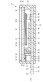
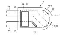
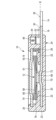
図1及び図2は、それぞれ、本発明に係る温度依存型スイッチの第1の実施形態の概略断面図を示す。このスイッチは、その全体として符号10で表される。
1 and 2 each show a schematic cross-sectional view of a first embodiment of a temperature-dependent switch according to the present invention. The switch is generally designated by the
図1は、スイッチ10の閉塞位置を示す。図2は、スイッチ10の開放位置を示す。
Figure 1 shows the
スイッチ10は、その温度に応じて、その閉塞位置からその開放位置へ、および開放位置から閉塞位置へスイッチ10を切り替えるように構成された温度依存型のスイッチング機構12を有する。
The
図1に示されたスイッチの閉塞位置において、スイッチング機構12は、スイッチ10の2つの外部端子14、16の間に導電性接続を確立する。これに対し、図2に示すスイッチ10の開放位置では、スイッチング機構12は、第1の外部端子14と第2の外部端子16との導電性接続を切断する。
In the closed position of the switch shown in FIG. 1, the
第1の外部端子14は、第1の電極18に導電的に接続されている。図1及び図2に示す第1の例示的な実施形態では、この第1の電極18は、同時に、スイッチ10のカバーを形成する。換言すれば、第1の電極18は、金属からなるカバー部19によって形成されている。
The first
第2の外部端子16は、第2の電極20に電気的に接続されている。ここに示す例示的な実施形態において、第2の電極20は、第2の外部端子16に一体に接続されている。つまり、同一の金属シートが、第2の電極20と第2の外部端子16とを形成している。
The second
2つの電極18、20は、平面状の電極として形成される。スイッチング機構12は、2つの電極18、20の間の空間内にスイッチ10の内側に配置される。
The two
2つの電極18、20は、スイッチ10のハウジング24の一部を形成する絶縁材料キャリア22によって、互いに離れた場所に保たれている。絶縁材料キャリア22は、2つの電極18、20を担持し、電極18、20をその配置で固定する。したがって、2つの電極18、20は、不動の固定された電極である。
The two
2つの電極18、20は、絶縁材料キャリア22によって垂直方向に沿って互いに距離を保っている。図1及び図2において矢印hによって示されているこの垂直方向は、2つの電極18、20に対して、横方向に、好ましくは直交方向に延びている。
The two
第1の電極18は、スイッチング機構12の上側(ここでは「第1の側」と呼ぶ)に配置され、第2の電極20は、スイッチング機構12の下側(ここでは「第2の側」と呼ぶ)に垂直方向hで反対側に配置される。
The
絶縁材料キャリア22は、本質的にポット状に形成されている。絶縁材料キャリア22は、ハウジング24の下部23を形成している。絶縁材料キャリア22は、第2の電極20がハウジングの下部23と一体部品となるようにオーバーモールドまたはポッティングすることによって第2の電極20の周囲に形成される。
The insulating
ハウジングの下部23は、カバー部19として形成された第1の電極18によって閉塞されている。カバー部19は、その全周に沿って、絶縁材料キャリア22によって囲まれ、絶縁材料キャリア22のホットエンボスされた上側縁部と下部23によって、その上に捕捉的に保持される。
The
また、絶縁材料キャリア22には、導電性材料からなるライン接続要素26も一体化されている。このライン接続要素26は、例えば、絶縁材料キャリア22に一体化された導電性プレートまたは他の何らかの導電体であってもよく、従って、ハウジング24内に配置されているにもかかわらず、同じくハウジング24内に配置されたスイッチング機構12から電気的に絶縁されている。なお、ここに示す例示的な実施形態は、ライン接続要素26は、横断面がL字状に形成されている。
Also integrated into the insulating
ライン接続要素26は、第1の外部端子14に第1の電極18を接続する。このようにして、垂直方向hにオフセットされた2つの電極18、20の配置にもかかわらず、2つの外部端子14、16を同じ高さで内側から外側へ絶縁材料キャリア22を通して導くことが可能になる。第1の外部端子14は従って図1及び図2に示す断面図において第2の外部端子16の「後方」に配置される、何故なら、第1の外部端子14は第2の外部端子16と同じ高さに配置されており、第2の外部端子16と平行に延びているからである。後者については、図4に示された上からの平面図との結合して考察することによって特に判ることができる。
The
図4に示すように、2つの外部端子14,16は、絶縁材料キャリア22の外側で互いに平行に延び、ライン接続要素26により、図1及び図2に破線で示すような共通の接続面Eに配置することができる。より詳細には、2つの外部端子14、16の2つの上側の側部28、30は、特に共通の接続面E内にある。2つの外部端子14、16は、平板状または板状の接続部として形成されることが好ましい。
As shown in FIG. 4, the two
図1及び図2に示す第1の実施形態では第2の電極20の上側も接続面E内に配置されているが、第1の電極18は、接続面Eに垂直方向hで平行にオフセットされて配置されている。また、接続面Eは、垂直方向hに対して直交して配列されていることが好ましい。
In the first embodiment shown in Figures 1 and 2, the upper side of the
2つの外部端子14、16の上に電気的に加熱性の抵抗部品32が位置する。この加熱性の抵抗部品32は、スイッチング機構12と電気的に並列に接続されており、また、ハウジング24の内部で、絶縁材料キャリア22の別個に設けられた凹部34内に、スイッチング機構12と横方向に並んで配置されているが、スイッチング機構12から空間的に分離されている。
An electrically heatable
加熱性の抵抗部品32は、本質的に自己保持機能のために機能し、該自己保持機能を用いて、スイッチ10によって保護されるべきデバイスがスイッチ10から独立して非通電にされるまで、スイッチング機構12によって開かれた後にスイッチ10を開かれたままにする。
The heated
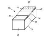
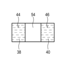
加熱性の抵抗部品32は、PTC材で構成された略立方体の部品36を有している。このPTCブロック36上には、導電性材料からなる2つの接触要素38、40が配置されている。これらの2つの接触要素38、40は、例えば、夫々金属シートとして形成され、PTCブロック36に固定される。2つの接触要素38,40は、PTCブロック36の同一側部42上に配置されている。この側部42は、加熱性の抵抗部品32の「接続側」と言及される。
The heatable
接続側42には、2つの接触要素38、40の夫々が接触領域44、46を有している。2つの接触領域44、46は、1つの同じ接触面K内に存在し、この接触面Kは、加熱性の抵抗部品32の設置状態において、接続面Eと一致している。第1の接触領域44は、第1の接触要素38上に配置され、第1の外部端子14において加熱性の抵抗部品32を電気的に接触させる働きをする。第2の接触領域46は、第2の接触要素40上に配置され、加熱性の抵抗部品32を第2の外部端子16と電気的に接触させる働きをする。
On the
加熱性の抵抗部品32は、スイッチ10の2つの外部端子14、16の上部に平坦に位置し、第1の接触領域44は、第1の外部端子14の上側28に存在し、第2の接触領域46は、第2の外部端子16の上側30に存在する。
The heated
2つの接触領域44、46と上側28、30との間の接触圧力を高めるために、加熱性の抵抗部品32は、その接続側42が圧縮ばね48の助けを得て、2つの外部端子14、16に対して押しつけられる。この圧縮ばね48は、接続側42と反対側に横たわる上側50の加熱性の抵抗部品32に作用する。上側50では、加熱性の抵抗部品32は、絶縁層52によって覆われて、PTCブロック36を圧縮ばね48から電気的に絶縁することができる。
To increase the contact pressure between the two
2つの接触要素38、40を互いに絶縁することについては、接触中断要素54を接触要素38、40の間に配置することもできる(図3A及び図3B参照)。これに代わるものとして、加熱性の抵抗部品32の2つの接触要素38、40は、ギャップ(空隙)によって互いに隔てられている。
To insulate the two
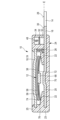
また、2つの外部端子14、16及び加熱性の抵抗部品32の基本的な配置は、図4からも分かる。図4はスイッチ10の上方からの平面図を示し、ここで、ハウジング24の内側に配置されたいくつかの部品(例えば、部品20及び26)は、破線によって示される。図4に破線で示す第2の電極20は、第2の外部端子16に対して斜めに又は斜めに延びているが、既に述べたように、第2の外部端子16と接続面E内にて共に位置する。しかし、第2の電極20は、図4に示すように、第2の外部端子16に対して必ずしも角度を持って又は斜めに延びている必要はない。また、第2の電極20は、原則として第1の外部端子16と並んでいてもよい。このような場合には、第2の外部端子16は、スイッチハウジング24の半径方向に第2の電極20と共に延びることが好ましい。第2の外部端子16が中央に、すなわち図4に示す位置に対して第1の外部端子14の方向に下方に平行にオフセットして配置されている場合、2つの外部端子14,16の平行配置も可能である。図4を参照すると、第2の外部端子16及び第2の電極20は、ハウジングの中央で第1の外部端子14と平行に一列に配置される。
The basic arrangement of the two
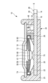
また、図5乃至図8に示された本発明に係るスイッチ10の例示的な実施形態においても、外部端子14、16の2つの上側28、30は、共通の接続面に配置され、加熱性の抵抗部品32は、スイッチ10の自己保持機能を実現するために設けられ、ここで、加熱性の抵抗部品32は、その2つの接触領域44、46とともに、2つの外部端子14、16の上側28、30の上に、共通の接触面K内に位置する。
図3A及び図3Bで原理的に概説した加熱性の抵抗部品32の構成と同様に、加熱性の抵抗部品32を配置および接触させるためのこの基本原理は、したがって、図5乃至図8に示す例示的な実施形態でも実施される。図5乃至図8に示された2つの例示的な実施形態は、スイッチング機構12の構成の機能的および構造的な種類、および、以下に説明するハウジング24のいくつかの特徴において、図1及び図2に示す第1の例示的な実施形態とは異なる。
Also in the exemplary embodiment of the
This basic principle for positioning and contacting the heatable
図1及び図2に示す第1の例示的な実施形態では、スイッチング機構12は、温度依存型のスイッチング要素56を有し、このスイッチング要素は、ばね要素58と電気的および機械的に直列に接続される。温度依存型のスイッチング要素56は、第1の例示的な実施形態において、バイメタル要素として形成され、バイメタル要素は細長いばね舌状の形状を有する。ばね要素58は、金属で作られ、また、細長いばね舌状として形成される。
In a first exemplary embodiment shown in Figures 1 and 2, the
ばね要素58の第1の端部60は、材料接合によって第1の電極18に固定される。この第1の端部60から開始して、ばね要素58は、片持ち梁の態様で、スイッチ10の内側の凹部61によって形成された空隙内に突出する。ばね要素58の反対側の第2の自由端部62は温度依存型のスイッチング要素56の第1の端部64に材料接合(例えば、半田付けまたは溶接によって)で固定される。第1の端部64と反対側の第2の端部66において、温度依存型のスイッチング要素56は、第2の電極20上に配置された固定の接触部70と相互作用する可動の接触部68を担持する。
A
ばね要素58及び温度依存型のスイッチング要素56の閉塞位置において、可動の接触部68は、固定の接触部70に対して押圧され、これにより、スイッチ10は閉塞され、2つの外部端子14、16間の導電性接続が確立される。
In the closed position of the
これを起点として、スイッチ10を流れる電流が増加した結果、または外気温が上昇した結果、スイッチング要素56の温度が上昇すると、最初に、スイッチング要素56のクリープ段階が始まり、そのばね要素58の力に対して作用するばね力が弱まる段階となる。スイッチング要素56とばね要素58との機械的な直列接続により、スイッチング要素56の力のこの減少は、ばね要素58により補償され、その結果、可動の接触部68は、固定の接触部70に押し付けられたままである。
Starting from this, if the temperature of the switching
そして、スイッチング要素56の温度が、スイッチング要素56の応答温度まで、又は応答温度を超えて更に上昇すると、スイッチング要素56は、図2に示されたその高温構成にスナップし、それによって、スイッチング機構12がその開放位置に持ち込まれ、2つの外部端子14、16間の導電性接続が遮断される。
And when the temperature of the switching
したがって、図2に示されたスイッチ10の開放位置では、第1の外部端子14からスイッチング機構12を経て第2の外部端子16に至るまでは、もはや電流は流れない。しかし、小さな残留電流は、加熱性の抵抗部品32を経て2つの外部端子14、16の間に依然として流れる。この残留電流によって、加熱性の抵抗部品32が自動的に加熱される。結果として生じる熱の進行は、スイッチング機構12および関連する温度依存型のスイッチング要素56にも伝達される。したがって、加熱性の抵抗部品32は、スイッチ10のいわゆる自己保持をもたらし、これによって、外部からの電圧が2つの外部端子14、16の間にもはや存在しなくなるまで、スイッチ10は、恒久的に開放状態に維持される。これは、通常、スイッチ10によって監視されるデバイスが、例えば、電源から取り外されることによって、非通電にされた場合に限られる。
2, no current flows from the first
スイッチング機構12と電気的に平行に接続されている加熱性の抵抗部品32がなければ、スイッチング機構12は、スイッチ10によって監視されるデバイスの温度、ひいてはスイッチ10の温度が再び低下するとすぐに、図1に示す閉塞位置に自動的に切り替わる。
If there were no heated
図5及び図6に示された第2の例示的な実施形態では、スイッチ10の温度依存型のスイッチング挙動は、構造的にかつ機能的に異なって構成されたスイッチング機構12によってもたらされる。しかしながら、加熱性の抵抗部品32によってもたらされる上述の自己保持原理も、ここでは保持される。2つの外部端子14、16に片側が接触する加熱性の抵抗部品32の前述のタイプの配置も、図5及び図6に示す本発明による温度依存型スイッチの例示的な実施形態において実施される。
In a second exemplary embodiment shown in Figs. 5 and 6, the temperature-dependent switching behavior of the
図5及び図6に示すスイッチ10では、スイッチング機構12は、温度依存型のスイッチング要素56および温度依存型のばね要素58を含む。このスイッチング要素56は、ここではディスク状のバイメタル要素として形成されているため、バイメタルディスクとも呼ばれる。ばね要素58は、また、ディスク形状であり、好ましくは、ばねスナップディスクとして形成され、このばねスナップディスクは、2つの温度に依存しない安定な形態を有し、2つの形態の間で力の影響を受けて前後にスナップする。
In the
図5及び図6に示す第2の例示的実施形態では、スイッチング要素56及びばね要素58は、互いに電気的に機械的に並列に接続されている。可動の接触部68は、材料接合でばね要素58に締結される。バイメタルディスクとして形成されたスイッチング要素56は、その中央に設けられた穴72で可動の接触部68上を滑るようにされる。
In a second exemplary embodiment shown in Figs. 5 and 6, the switching
また、カバー部19は、第1の実施形態と同様に、金属製であることが好ましく、第1の電極18として機能する。前述同様に、第1の電極18は、絶縁材料キャリア22内に埋め込まれたライン接続要素26によって、第1の外部端子14に導電的に接続される。
As in the first embodiment, the
絶縁材料キャリア22に埋め込まれ、少なくともある部分において、接続面Eにおいて外部端子14、16とともにあり、加熱性の抵抗部品32の接触領域44、46も配置されている金属シートが、第2の電極20として機能する。
A metal sheet embedded in the insulating
なお、第1の実施形態とは異なり、固定の接触部70は、材料接合で第2の電極20に接続される別個の部品として形成されるのではなく、第2の電極20自体の中央部が高くなって形成される。
Unlike the first embodiment, the fixed
図5に示されたスイッチ10の閉塞位置において、ディスク状のばね要素58は、その外縁74がカバー部19の内側、ひいては第1の電極18に支持されている。スイッチ10のこの閉塞位置において、温度依存型のスイッチング要素56は、いかなる力もない状態で取り付けることができ、その外縁76と共にスイッチ10の内部に形成された凹部61内に自由に突出することができる。したがって、スイッチング要素56は、例示的な第1の実施形態とは異なり、スイッチ10の閉塞位置においてスイッチング要素56を通って流れる電流を有さない。
5, the disk-shaped
スイッチ10の閉塞位置において、電流は、ライン接続要素26を経由して第1の外部端子14から第1の電極18に流れ込み、そこからばね要素58、可動の接触部68、固定の接触部70及び第2の電極20を経由して第2の外部端子16に流れる。
In the closed position of the
同様に、図5に示されたスイッチの閉塞位置では、温度依存型のスイッチング要素56は、可動の接触部68が固定の接触部70に対して押される接点圧力に寄与しない。図5及び図6に示すスイッチング機構12の構成では、この閉塞圧力は、ばね要素58によってもたらされるだけである。
Similarly, in the closed position of the switch shown in FIG. 5, the temperature dependent switching
スイッチ10、ひいてはスイッチング機構12の温度が、スイッチング要素56の応答温度にまで、又は応答温度を超えて上昇した場合には、スイッチング要素56は、図5に示されるその凸状位置から、図6に示されるその凹状位置にスナップする。この場合、スイッチング要素56は、その外縁76を絶縁材料キャリア22上に載せて支持され、ばね要素58を図5に示されるその凹状位置から図6に示されるその凸状位置に押圧し、これにより、可動の接触部68は固定の接触部70から持ち上げられ、スイッチング機構12によって確立された導電性接続が開放される。
If the temperature of the
図6に示すスイッチング機構12の開放位置では、電流は、加熱性の抵抗部品32を通じてのみ第1の外部端子14と第2の外部端子16との間を流れ、これは、前述したように、加熱され、電源が完全に中断されるまで、スイッチ10を開放位置に維持する。
In the open position of the
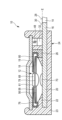
図7及び図8に示す発明に係るスイッチ10の第3の例示的な実施形態では、スイッチング機構12は、図5及び図6に示す発明に係るスイッチ10の第2の例示的な実施形態に係るスイッチング機構12と同様に機能的に同様に形成される。スイッチング要素56及びばね要素58は、機械的及び電気的に並列に接続されている。さらに、図7及び図8に示される第3の例示的な実施形態においても、スイッチング要素56及びばね要素58はディスク状又は円形のディスク状であり、夫々の中心によって可動の接触部68に接続されている。
In the third exemplary embodiment of the
しかしながら、この場合のスイッチング要素56及びばね要素58は、可動の接触部68の外縁を形成する周縁カラー74に対して、反対側から位置している。
However, in this case the switching
図7及び図8に示すスイッチ10の第3の実施形態に係るスイッチング機構12は、スイッチング要素56、ばね要素58および可動の接触部68に加えて、スイッチング機構のハウジング80を有する。このスイッチング機構のハウジング80は、金属製であることが好ましい。スイッチング機構のハウジング80は、スイッチング要素56、ばね要素58および可動の接触部68により形成されるスイッチング機構12またはスイッチング機構ユニットを収納するために用いられる。
The
スイッチング機構のハウジング80は、部分的に開放されたハウジングとして形成され、好ましくは金属で形成される。スイッチング要素56、ばね要素58および可動の接触部68によって形成されるスイッチング機構ユニットは、捕捉的に、しかし遊びをもって、スイッチング機構のハウジング80内に保持される。
The
このようなスイッチング機構のハウジング80の助けにより、スイッチング機構12を半製品として予め製造し、品目として在庫として保持し、全体としてスイッチハウジング24に挿入することが可能となる。
With the aid of such a
図7に示すスイッチの閉塞位置では、ばね要素58は、その外縁74がスイッチング機構のハウジング80の内側に支持され、可動の接触部68を固定の接触部70に対して押圧する。また、スイッチング機構12のこの例示的な実施形態では、スイッチ10の閉塞位置において、スイッチング要素56は、いかなる力も伴わずに機械的に取り付けられ、スイッチング要素56を通って流れる電流を有さない。
7, the
図7及び図8に示すスイッチ10において、スイッチング機構のハウジング80は、スイッチング機構12の第1の電極18として作用する。従って、カバー部19は、ここでは導電性材料から形成される必要はなく、例えば、ハウジング24の下部23を形成する絶縁材料キャリア22と類似又は更に同一の材料からなるプラスチックから形成されるのが良い。
In the
また、カバー部19がプラスチック製の場合には、加熱性の抵抗部品32も圧縮ばね48に対して電気的に絶縁する必要はなく、そのために絶縁層52を省くことが可能である。加熱性の抵抗部品32もまた、下側または接続側42の接触部44、46を、外部端子14、16の上側28、30に直接当ててここに配置される。
Also, if the
第1の電極18として作用するスイッチング機構のハウジング80は、ライン接続要素26上に位置し、ここでもスイッチ内に設けられたライン接続要素26が、第1の電極18と第1の外部端子14との間に電気的接触を確立し、2つの外部端子14、16を同じ高さで取り付けるか、または外部端子14、16を絶縁材料キャリア22から同じ高さで導出することができる。
The
なお、図7に示すスイッチの閉塞位置における電流は、第1の外部端子14から、ライン接続要素26、スイッチング機構のハウジング80(第1の電極18)、ばね要素58、可動の接触部68、固定の接触部70及び第2の電極20を経由して第2の外部端子16へと流れる。
In addition, when the switch is in the closed position shown in FIG. 7, the current flows from the first
図8に示すスイッチ10の開放位置では、温度依存型のスイッチング要素56は、その外縁76がスイッチング機構のハウジング80の内側に支持され、可動の接触部68を上方に押圧することによって、可動の接触部68が固定の接触部70から持ち上げられ、スイッチング機構12を経由した電流流れが遮断される。したがって、ばね要素58もまた、図7に示すその凹状位置から図8に示すその凸状位置にスナップされる。
In the open position of the
また、開放位置は、加熱性の抵抗部品32によってもたらされる自己保持によって、2つの外部端子14、16の間にもはや何の電位もなくなるまで、ここで開放されたままにされる。
The open position is then maintained by the self-retention provided by the heated
したがって、ここで示される3つの例示的な実施形態は、スイッチング機構12の構成において本質的に異なり、その一方、加熱性の抵抗部品32によってもたらされる自己保持の原理、ならびに加熱性の抵抗部品32の配置および電気的接触のタイプ、ならびに共通の接続面Eにおける2つの外部端子14、16の取り付けは、スイッチの内側に配置されるライン接続要素26を設けることによって、3つの例示的な実施形態の全てにおいて、原理的に同様の方法で実施される。
Thus, the three exemplary embodiments shown here differ essentially in the configuration of the
Claims (14)
2つの外部端子(14,16)は、第1の外部端子(14)の上側(28)が第2の外部端子(16)の上側(30)と共通の接続面(E)内に位置するように、ハウジングの外側に互いに並んで平行に導出され、
ハウジング(24)の内部には電気的に加熱性の抵抗部品(32)が配置されており、この加熱性の抵抗部品(32)はスイッチング機構(12)と電気的に並列に接続されて、接続側(42)に、第1の外部端子(14)の上側(28)に電気的に接触する第1の接触領域(44)と、第2の外部端子(16)の上側(30)に電気的に接触する第2の接触領域(46)とを有し、
前記ハウジング(24)は、第1の外部端子(14)に電気的に接続された第1の固定電極(18)と第2の外部端子(16)と電気的に接続された第2の固定電極(20)とを担持し、両電極を垂直方向(h)に沿って互いに距離を置いて維持される絶縁材料キャリア(22)を有し、ここで、温度依存型のスイッチング機構(12)は、ハウジング(24)の内部において、第1の固定電極(18)と第2の固定電極(20)との間の絶縁材料キャリア(22)の凹部(61)に配置されており、第1の固定電極(18)は、ハウジング(24)内に配置されたライン接続要素(26)を介して、第1の外部端子(14)に電気的に接続され、第1の外部端子及び第2の外部端子(14、16)は、垂直方向(h)に対して同じ高さで絶縁材料キャリア(22)を通って導出されることを特徴とする、温度依存型スイッチ(10)。 a housing (24) and a temperature dependent switching mechanism (12) disposed within the housing (24), the switching mechanism (12) configured to switch, in response to a temperature thereof, between a closed position in which a conductive connection is established between a first external terminal (14) and a second external terminal (16) and an open position in which the switching mechanism (12) breaks the conductive connection;
The two external terminals (14, 16) are led out parallel to each other on the outside of the housing so that the upper side (28) of the first external terminal (14) and the upper side (30) of the second external terminal (16) are located within a common connection plane (E);
an electrically heatable resistive element (32) disposed within the housing (24), the heatable resistive element (32) being electrically connected in parallel with the switching mechanism (12) and having a first contact area (44) on a connecting side (42) in electrical contact with the upper side (28) of the first external terminal (14) and a second contact area (46) in electrical contact with the upper side (30) of the second external terminal (16);
the housing (24) has an insulating material carrier (22) carrying a first fixed electrode (18) electrically connected to the first external terminal (14) and a second fixed electrode (20) electrically connected to the second external terminal (16), the electrodes being maintained at a distance from each other along the vertical direction (h), the temperature-dependent switching mechanism (12) being arranged inside the housing (24) in a recess (61) of the insulating material carrier (22) between the first fixed electrode (18) and the second fixed electrode (20), the first fixed electrode (18) being electrically connected to the first external terminal (14) via a line connection element (26) arranged inside the housing (24), the first external terminal (14) and the second external terminal (16) being led out through the insulating material carrier (22) at the same height relative to the vertical direction (h) .
Applications Claiming Priority (2)
| Application Number | Priority Date | Filing Date | Title |
|---|---|---|---|
| DE102023102303.9A DE102023102303B3 (en) | 2023-01-31 | 2023-01-31 | Temperature dependent switch |
| DE102023102303.9 | 2023-01-31 |
Publications (2)
| Publication Number | Publication Date |
|---|---|
| JP2024109076A JP2024109076A (en) | 2024-08-13 |
| JP7686811B2 true JP7686811B2 (en) | 2025-06-02 |
Family
ID=89662113
Family Applications (1)
| Application Number | Title | Priority Date | Filing Date |
|---|---|---|---|
| JP2024009302A Active JP7686811B2 (en) | 2023-01-31 | 2024-01-25 | Temperature Dependent Switch |
Country Status (7)
| Country | Link |
|---|---|
| US (1) | US20240258053A1 (en) |
| EP (1) | EP4411777B1 (en) |
| JP (1) | JP7686811B2 (en) |
| CN (1) | CN118431025A (en) |
| DE (1) | DE102023102303B3 (en) |
| DK (1) | DK4411777T3 (en) |
| ES (1) | ES3051683T3 (en) |
Families Citing this family (2)
| Publication number | Priority date | Publication date | Assignee | Title |
|---|---|---|---|---|
| DE102023102302B3 (en) * | 2023-01-31 | 2024-03-28 | Marcel P. HOFSAESS | Temperature dependent switch |
| DE102023127597B3 (en) | 2023-10-10 | 2025-02-13 | Marcel P. HOFSAESS | temperature-dependent switch |
Citations (1)
| Publication number | Priority date | Publication date | Assignee | Title |
|---|---|---|---|---|
| JP2017224570A (en) | 2016-06-17 | 2017-12-21 | 旭計器株式会社 | thermostat |
Family Cites Families (14)
| Publication number | Priority date | Publication date | Assignee | Title |
|---|---|---|---|---|
| JPH039283Y2 (en) * | 1984-09-20 | 1991-03-08 | ||
| JPH0433226A (en) * | 1990-05-28 | 1992-02-04 | Matsushita Electric Works Ltd | Thermal protector |
| DE19727197C2 (en) * | 1997-06-26 | 1999-10-21 | Marcel Hofsaess | Temperature-dependent switch with contact bridge |
| DE19752581C2 (en) * | 1997-11-27 | 1999-12-23 | Marcel Hofsaes | Switch with a temperature-dependent switching mechanism |
| US6097274A (en) * | 1998-02-23 | 2000-08-01 | Hofsaess; Marcel | Switch having a temperature-dependent switching member and a substantially temperature-independent spring element |
| DE19807288C2 (en) | 1998-02-23 | 2001-09-20 | Marcel Hofsaes | Temperature-dependent switch |
| DE19816809C2 (en) * | 1998-04-16 | 2001-10-18 | Thermik Geraetebau Gmbh | Temperature-dependent switch |
| DE19917631A1 (en) * | 1999-04-19 | 2000-10-26 | Votup & Co Innovative Keramik | Temperature sensitive and temperature compensated electronic circuit e.g. for temperature protection function, uses material with temperature dependent resistance characteristics or bimetal element separating on excess temperature |
| DK2038905T3 (en) | 2006-07-11 | 2011-01-10 | Thermik Geraetebau Gmbh | Connecting element and coupling device with connecting element |
| CN102007561B (en) * | 2008-04-18 | 2014-07-02 | 泰科电子日本合同会社 | Circuit protection device |
| DE112012002681B4 (en) * | 2011-06-28 | 2018-06-14 | Uchiya Thermostat Co., Ltd. | Motor protection switch |
| JP6334677B2 (en) * | 2014-02-25 | 2018-05-30 | ウチヤ・サーモスタット株式会社 | Temperature switch |
| CN205542584U (en) | 2016-01-28 | 2016-08-31 | 苏州工业园区凯恩电子科技有限公司 | Combined type temperature controller |
| DE102023102302B3 (en) * | 2023-01-31 | 2024-03-28 | Marcel P. HOFSAESS | Temperature dependent switch |
-
2023
- 2023-01-31 DE DE102023102303.9A patent/DE102023102303B3/en active Active
-
2024
- 2024-01-19 EP EP24152791.0A patent/EP4411777B1/en active Active
- 2024-01-19 ES ES24152791T patent/ES3051683T3/en active Active
- 2024-01-19 DK DK24152791.0T patent/DK4411777T3/en active
- 2024-01-25 JP JP2024009302A patent/JP7686811B2/en active Active
- 2024-01-30 CN CN202410129074.9A patent/CN118431025A/en active Pending
- 2024-01-30 US US18/426,647 patent/US20240258053A1/en active Pending
Patent Citations (1)
| Publication number | Priority date | Publication date | Assignee | Title |
|---|---|---|---|---|
| JP2017224570A (en) | 2016-06-17 | 2017-12-21 | 旭計器株式会社 | thermostat |
Also Published As
| Publication number | Publication date |
|---|---|
| DK4411777T3 (en) | 2025-11-17 |
| EP4411777A1 (en) | 2024-08-07 |
| CN118431025A (en) | 2024-08-02 |
| DE102023102303B3 (en) | 2024-03-28 |
| ES3051683T3 (en) | 2025-12-29 |
| US20240258053A1 (en) | 2024-08-01 |
| JP2024109076A (en) | 2024-08-13 |
| EP4411777B1 (en) | 2025-08-13 |
Similar Documents
| Publication | Publication Date | Title |
|---|---|---|
| JP7686811B2 (en) | Temperature Dependent Switch | |
| US8289124B2 (en) | Temperature-dependent switch | |
| US5973587A (en) | Temperature-dependent switch having a contact bridge | |
| US5757261A (en) | Temperature controller having a Bimetallic element and plural heating components | |
| US6031447A (en) | Switch having a temperature-dependent switching mechanism | |
| JPH0430130B2 (en) | ||
| CA1195364A (en) | Thermostatic switch with thermal override | |
| JPH05121605A (en) | Circuit layout | |
| US20150042443A1 (en) | Temperature-dependent switch | |
| US12482620B2 (en) | Temperature-dependent switch | |
| CN111834166A (en) | Thermostatic switch and method for manufacturing thermostatic switch | |
| JP2002124172A (en) | Thermal protector | |
| JP4463088B2 (en) | Low current electric motor protection device | |
| CN119811929A (en) | Temperature dependent switching | |
| CN117438248A (en) | Temperature-dependent switching mechanism and temperature-dependent switch having such a switching mechanism | |
| US11195679B2 (en) | Temperature-dependent switch | |
| US6091316A (en) | Switch having a temperature-dependent switching mechanism | |
| US20240258052A1 (en) | Temperature-dependent switch | |
| JP7686808B2 (en) | Temperature Dependent Switch | |
| CN1134807C (en) | Improvements relating to thermal controls for electric heating elements | |
| US20160027598A1 (en) | Temperature-dependent switch with insulating film | |
| US4673909A (en) | Thermal cutout | |
| DK3024010T3 (en) | Temperature dependent contact | |
| US12444560B2 (en) | Temperature-dependent switch | |
| JP3247736U (en) | Thermal pellet type thermal fuse |
Legal Events
| Date | Code | Title | Description |
|---|---|---|---|
| A621 | Written request for application examination |
Free format text: JAPANESE INTERMEDIATE CODE: A621 Effective date: 20240125 |
|
| A977 | Report on retrieval |
Free format text: JAPANESE INTERMEDIATE CODE: A971007 Effective date: 20241205 |
|
| A131 | Notification of reasons for refusal |
Free format text: JAPANESE INTERMEDIATE CODE: A131 Effective date: 20241210 |
|
| A521 | Request for written amendment filed |
Free format text: JAPANESE INTERMEDIATE CODE: A523 Effective date: 20250305 |
|
| TRDD | Decision of grant or rejection written | ||
| A01 | Written decision to grant a patent or to grant a registration (utility model) |
Free format text: JAPANESE INTERMEDIATE CODE: A01 Effective date: 20250430 |
|
| A61 | First payment of annual fees (during grant procedure) |
Free format text: JAPANESE INTERMEDIATE CODE: A61 Effective date: 20250521 |
|
| R150 | Certificate of patent or registration of utility model |
Ref document number: 7686811 Country of ref document: JP Free format text: JAPANESE INTERMEDIATE CODE: R150 |