JP7679155B2 - Hydrogen Production/Storage System - Google Patents
Hydrogen Production/Storage System Download PDFInfo
- Publication number
- JP7679155B2 JP7679155B2 JP2024574689A JP2024574689A JP7679155B2 JP 7679155 B2 JP7679155 B2 JP 7679155B2 JP 2024574689 A JP2024574689 A JP 2024574689A JP 2024574689 A JP2024574689 A JP 2024574689A JP 7679155 B2 JP7679155 B2 JP 7679155B2
- Authority
- JP
- Japan
- Prior art keywords
- hydrogen production
- hydrogen
- storage system
- hydraulic drive
- mounting body
- Prior art date
- Legal status (The legal status is an assumption and is not a legal conclusion. Google has not performed a legal analysis and makes no representation as to the accuracy of the status listed.)
- Active
Links
Images


Classifications
-
- B—PERFORMING OPERATIONS; TRANSPORTING
- B63—SHIPS OR OTHER WATERBORNE VESSELS; RELATED EQUIPMENT
- B63B—SHIPS OR OTHER WATERBORNE VESSELS; EQUIPMENT FOR SHIPPING
- B63B35/00—Vessels or similar floating structures specially adapted for specific purposes and not otherwise provided for
-
- B—PERFORMING OPERATIONS; TRANSPORTING
- B63—SHIPS OR OTHER WATERBORNE VESSELS; RELATED EQUIPMENT
- B63B—SHIPS OR OTHER WATERBORNE VESSELS; EQUIPMENT FOR SHIPPING
- B63B35/00—Vessels or similar floating structures specially adapted for specific purposes and not otherwise provided for
- B63B35/44—Floating buildings, stores, drilling platforms, or workshops, e.g. carrying water-oil separating devices
-
- C—CHEMISTRY; METALLURGY
- C01—INORGANIC CHEMISTRY
- C01B—NON-METALLIC ELEMENTS; COMPOUNDS THEREOF; METALLOIDS OR COMPOUNDS THEREOF NOT COVERED BY SUBCLASS C01C
- C01B3/00—Hydrogen; Gaseous mixtures containing hydrogen; Separation of hydrogen from mixtures containing it; Purification of hydrogen
- C01B3/02—Production of hydrogen or of gaseous mixtures containing a substantial proportion of hydrogen
-
- F—MECHANICAL ENGINEERING; LIGHTING; HEATING; WEAPONS; BLASTING
- F03—MACHINES OR ENGINES FOR LIQUIDS; WIND, SPRING, OR WEIGHT MOTORS; PRODUCING MECHANICAL POWER OR A REACTIVE PROPULSIVE THRUST, NOT OTHERWISE PROVIDED FOR
- F03B—MACHINES OR ENGINES FOR LIQUIDS
- F03B13/00—Adaptations of machines or engines for special use; Combinations of machines or engines with driving or driven apparatus; Power stations or aggregates
- F03B13/12—Adaptations of machines or engines for special use; Combinations of machines or engines with driving or driven apparatus; Power stations or aggregates characterised by using wave or tide energy
- F03B13/26—Adaptations of machines or engines for special use; Combinations of machines or engines with driving or driven apparatus; Power stations or aggregates characterised by using wave or tide energy using tide energy
-
- F—MECHANICAL ENGINEERING; LIGHTING; HEATING; WEAPONS; BLASTING
- F03—MACHINES OR ENGINES FOR LIQUIDS; WIND, SPRING, OR WEIGHT MOTORS; PRODUCING MECHANICAL POWER OR A REACTIVE PROPULSIVE THRUST, NOT OTHERWISE PROVIDED FOR
- F03B—MACHINES OR ENGINES FOR LIQUIDS
- F03B9/00—Endless-chain machines or engines
Landscapes
- Engineering & Computer Science (AREA)
- Chemical & Material Sciences (AREA)
- Combustion & Propulsion (AREA)
- Mechanical Engineering (AREA)
- Organic Chemistry (AREA)
- Ocean & Marine Engineering (AREA)
- General Engineering & Computer Science (AREA)
- Architecture (AREA)
- Civil Engineering (AREA)
- Structural Engineering (AREA)
- Inorganic Chemistry (AREA)
- Life Sciences & Earth Sciences (AREA)
- General Life Sciences & Earth Sciences (AREA)
- Oceanography (AREA)
- Other Liquid Machine Or Engine Such As Wave Power Use (AREA)
Description
この発明は、水力発電で得た電気エネルギを用いて水素を製造及び貯蔵することができる水素製造/貯蔵システムに関するものである。 This invention relates to a hydrogen production/storage system that can produce and store hydrogen using electrical energy generated by hydroelectric power generation.
水素は、水を分解して得られることから、水素供給箇所の多くは、海水の利用が可能な海に近い場所に建設される。そして、海水を水素と酸素に分解する装置を駆動させる電力としては、火力発電所等で得られる商用の電力や風車型の風力発電装置で得られる電力が用いられる。 Because hydrogen is obtained by decomposing water, many hydrogen supply sites are built near the sea where seawater can be used. The electricity used to power the equipment that decomposes seawater into hydrogen and oxygen comes from commercial electricity generated by thermal power plants or from wind turbine-type wind power generation equipment.
しかし、陸地、特に、日本では、常に風が吹いている地域は少なく、また、風の強さも不安定である。このため、充分な水素を供給することが難しい。However, there are few areas on land, especially in Japan, where the wind blows constantly, and the strength of the wind is unstable. This makes it difficult to supply sufficient hydrogen.
そこで、風力発電を、常に風の吹く洋上等の場所で行って、充分な水素の製造及び貯蔵が行える水素製造/貯蔵システムが提案されている(例えば、特許文献1及び特許文献2参照)。
このシステムでは、風力による発電システムと、この風力発電システムで得た電力で水を電気分解して水素を製造する水素製造装置と、水素製造装置で得た水素を貯蔵するタンクとを、1つの船体に設けて、1隻の「水素製造船」を構成している。
これにより、この水素製造船を強い風力が得られる洋上まで航行して、充分な水素を製造することができる。そして、製造した水素を、水素製造船に貯蔵して所定の陸上までに輸送することができる。
In response to this, hydrogen production/storage systems have been proposed that can generate wind power in locations such as offshore where the wind always blows, and produce and store sufficient hydrogen (see, for example,
In this system, a wind-powered power generation system, a hydrogen production device that produces hydrogen by electrolyzing water using the electricity generated by the wind power generation system, and a tank for storing the hydrogen produced by the hydrogen production device are all installed on a single hull, forming a "hydrogen production ship."
This allows the hydrogen production ship to sail out to sea where strong winds are available and produce sufficient hydrogen, which can then be stored on board and transported to a designated location on land.
しかし、上記した従来の水素製造/貯蔵システムは、風力を主力として、発電する構成であるので、潮流等と比べて、所望強さの風力を安定的に得ることができない。また、強く安定した風力を得るためには、風車や帆が風向きと対向するように水素製造船を動かしながら調整する必要がある。洋上の風向きの変化は潮流の変化と比べて多様であり、かかる風向きの変化への対応操作が難しく、煩雑であった。 However, the conventional hydrogen production/storage systems described above are configured to generate electricity primarily using wind power, and therefore are unable to stably obtain wind power of the desired strength compared to tidal currents, etc. Furthermore, in order to obtain strong, stable wind power, it is necessary to adjust the movement of the hydrogen production ship so that the wind turbines and sails face the wind direction. Changes in wind direction at sea are more diverse than changes in tidal currents, and responding to such changes in wind direction is difficult and complicated.
この発明は、上述した課題を解決するためになされたもので、潮流を利用することにより、洋上での安定した水力発電が可能で且つ水力発電で得た電気を用いて水素製造及び貯蔵が可能な水素製造/貯蔵システムを提供することを目的とする。This invention has been made to solve the above-mentioned problems, and aims to provide a hydrogen production/storage system that can generate stable hydroelectric power at sea by utilizing tidal currents, and can produce and store hydrogen using the electricity generated by the hydroelectric power generation.
上記課題を解決するために、第1の発明は、水流圧に対応した回転力を出力可能な出力軸を有する水力駆動装置と、出力軸の回転力を受けて発電動作を行う発電装置と、これら水力駆動装置及び発電装置が取り付けられた取付体と、水素を海水から製造して貯蔵可能な水素製造船とを備えた水素製造/貯蔵システムであって、水力駆動装置は、取付体の一方端部側に回転自在に取り付けられた第1の回転体と、その回転中心軸が第1の回転体の回転中心軸と平行になるように取付体の他方端部側に回転自在に取り付けられた第2の回転体と、第1の回転体と第2の回転体とに巻き付けられた無端ベルトと、各抵抗部材が水流圧を受けるための凹状の受圧面部を有し且つ無端ベルトの表面に所定の間隔で立設された複数の第1の抵抗部材と、その回転中心軸が第1及び第2の回転体の回転中心軸と平行な状態で、第1の回転体と第2の回転体と無端ベルトとの間に配設され、且つ取付体に取り付けられた複数の補助回転体と、を備え、発電装置は、水力駆動装置の出力軸の回転力を回転軸で受けて発電動作を行う発電機を備え、水力駆動装置は、第1の回転体及び第2の回転体の少なくとも回転中心軸が水面の上方に位置し、且つ無端ベルトのうち第1の回転体及び第2の回転体よりも下側の無端ベルト部分に位置する複数の第1の抵抗部材が水中内に完没するように、取付体に取り付けられており、水素製造船は、海水を略真水にした後、真水を発電装置で発電された電気を用いて電気分解することにより、水素を製造する水素製造装置と、水素製造装置で製造した水素を貯蔵する水素貯蔵装置とを備えている構成とした。In order to solve the above problems, the first invention is a hydrogen production/storage system comprising a hydraulic drive unit having an output shaft capable of outputting a rotational force corresponding to water flow pressure, a power generation unit that receives the rotational force of the output shaft and generates electricity, a mounting body to which the hydraulic drive unit and the power generation unit are attached, and a hydrogen production ship capable of producing hydrogen from seawater and storing it, in which the hydraulic drive unit comprises a first rotor rotatably attached to one end side of the mounting body, a second rotor rotatably attached to the other end side of the mounting body so that its central axis of rotation is parallel to the central axis of rotation of the first rotor, an endless belt wound around the first rotor and the second rotor, a plurality of first resistance members each having a concave pressure-receiving surface portion for receiving water flow pressure and set up at predetermined intervals on the surface of the endless belt, and a plurality of first resistance members each having a concave pressure-receiving surface portion for receiving water flow pressure and a central axis of rotation of the first resistance member. and a plurality of auxiliary rotors arranged between the first rotor, the second rotor, and the endless belt in a state parallel to the central rotation axis of the second rotor and attached to the mounting body. The power generation device includes a generator that receives the rotational force of the output shaft of the hydraulic drive device at its rotating shaft to generate electricity. The hydraulic drive device is attached to the mounting body so that at least the central rotation axes of the first rotor and the second rotor are located above the water surface and a plurality of first resistance members located in the endless belt portion below the first rotor and the second rotor are completely submerged in water. The hydrogen production ship is configured to include a hydrogen production device that produces hydrogen by converting seawater into approximately fresh water and then electrolyzing the fresh water using electricity generated by the power generation device, and a hydrogen storage device that stores the hydrogen produced by the hydrogen production device.
かかる構成により、水素製造船を動かして、水力駆動装置と発電装置を、取付体と一体に所望の洋上位置まで移動させることができる。
そして、水素製造船を当該洋上に停留させて、水力駆動装置と発電装置とを、取付体と共に当該洋上位置に固定することができる。
これにより、海中に完没した複数の第1の抵抗部材が、水流圧を受け、無端ベルトが巻き付けられた第1の回転体と第2の回転体とが、潮流方向に回転する。そして、その回転力が水力駆動装置の出力軸に出力され、発電装置に伝達されて、発電動作が行われる。
発電装置で発電された電気は、水素製造船の水素製造装置に送電される。すると、水素製造装置が、この送られてきた電気を用いて、海水を吸い上げ、略真水に濾過する。水素製造装置は、この真水を電気分解して、水素を製造する。そして、水素貯蔵装置が、水素製造装置で製造された水素を貯蔵する。
流れが弱まった場合等、潮流に変化が生じた場合には、水素製造船を再駆動させて、所望の潮流が生じている洋上まで移動する。そして、水素製造船を当該洋上に再度停留させることで、当該洋上での水素の製造/貯蔵作業を行うことができる。
そして、水素貯蔵装置への貯蔵が完了したときは、水素製造船を駆動させて、貯蔵した水素を陸上の水素供給所まで輸送することができる。
With this configuration, the hydrogen production ship can be moved to a desired offshore position, together with the hydraulic drive unit and the power generation unit, together with the mounting body.
The hydrogen production ship can then be anchored offshore, and the hydraulic drive unit and the power generation unit can be fixed to the offshore position together with the mounting body.
As a result, the multiple first resistance members completely submerged in the sea are subjected to water current pressure, causing the first rotor and the second rotor around which the endless belt is wound to rotate in the direction of the tidal current. The torque is then output to the output shaft of the hydraulic drive device and transmitted to the power generation device, generating electricity.
The electricity generated by the power generation device is sent to the hydrogen production device on the hydrogen production ship. The hydrogen production device then uses the electricity sent thereto to draw up seawater and filter it into nearly fresh water. The hydrogen production device electrolyzes the fresh water to produce hydrogen. The hydrogen storage device then stores the hydrogen produced by the hydrogen production device.
If the current weakens or there is a change in the tide, the hydrogen production vessel can be restarted and moved to a location on the ocean where the desired tide is occurring. The hydrogen production vessel can then be anchored on the location again, allowing hydrogen production and storage operations to be carried out on the ocean.
Then, when storage in the hydrogen storage device is completed, the hydrogen production ship can be driven to transport the stored hydrogen to a hydrogen supply station on land.
第2の発明は、第1の発明に係る水素製造/貯蔵システムにおいて、取付体が、水素製造船の船体に設けられている構成とした。The second invention is a hydrogen production/storage system according to the first invention, in which the mounting body is provided on the hull of the hydrogen production ship.
かかる構成により、水力駆動装置と発電装置が設けられた取付体を、水素製造船と一体に、所望の洋上位置まで容易に移動させることができる。つまり、取付体に設けられた水力駆動装置と発電装置を、潮流のある場所ならどこにでも移動可能であり、しかも、水素製造船の移動時においても発電装置から水素製造船に電力を供給することができる。This configuration allows the mounting body, on which the hydraulic drive unit and the power generation unit are mounted, to be easily moved together with the hydrogen production ship to a desired offshore location. In other words, the hydraulic drive unit and the power generation unit mounted on the mounting body can be moved anywhere there is a tidal current, and the power generation unit can supply electricity to the hydrogen production ship even when the hydrogen production ship is moving.
第3の発明は、第1の発明に係る水素製造/貯蔵システムにおいて、取付体が、水素製造船とは別体の浮体具に設けられている構成とした。The third invention is a hydrogen production/storage system according to the first invention, in which the mounting body is provided on a floating device separate from the hydrogen production vessel.
かかる構成により、潮流の方向等の変化が激しい洋上においても、水素製造船の向きを、水力駆動装置及び発電装置が設けられた取付体と一体に変化させる必要がない。つまり、取付体が設けられた浮体具だけを、潮流の方向に合わせて変化させるだけで、対応することができる。
また、必要なときには、水素製造船だけを、陸上の水素貯蔵所等に帰航させることができる。
With this configuration, even when the hydrogen production ship is on the ocean where the direction of the tidal current changes drastically, it is not necessary to change the direction of the hydrogen production ship together with the mounting body on which the hydraulic drive unit and the power generation unit are mounted. In other words, it is possible to respond to the direction of the tidal current by simply changing the floating device on which the mounting body is mounted.
Furthermore, when necessary, the hydrogen production ship alone can be made to return to a land-based hydrogen storage facility or the like.
第4の発明は、第1の発明に係る水素製造/貯蔵システムにおいて、発電装置で発電された電気を蓄電可能な蓄電装置が、水素製造船又は取付体のいずれかに設けられている構成とした。The fourth invention is a hydrogen production/storage system according to the first invention, in which a power storage device capable of storing electricity generated by the power generation device is provided either in the hydrogen production ship or in the mounting body.
かかる構成により、発電装置で発電された電気を、水素製造船又は取付体のいずれかに設けられた蓄電装置に蓄電することができる。そして、蓄電装置に蓄電された電気を、水素製造装置や水素貯蔵装置の電源として用いることができる。With this configuration, electricity generated by the power generation device can be stored in a power storage device installed either on the hydrogen production ship or on the mounting body. The electricity stored in the power storage device can then be used as a power source for the hydrogen production device or hydrogen storage device.
第5の発明は、第1の発明に係る水素製造/貯蔵システムにおいて、第1の抵抗部材が、可撓性素材で形成された受圧面部と、受圧面部を無端ベルトの表面に起立させて支持する支持部材とで形成されている構成とした。The fifth invention is a hydrogen production/storage system according to the first invention, in which the first resistance member is formed of a pressure-receiving surface portion made of a flexible material and a support member that supports the pressure-receiving surface portion by raising it against the surface of the endless belt.
かかる構成により、水力駆動装置の第1の抵抗部材は、流れに対向する受圧面部で水流圧を受けて、第1の回転体及び第2の回転体を回転させる。そして、潮流の方向が変わった場合には、可撓性素材で形成された受圧面部が流れ方向に撓む。この結果、受圧面部が流れに対向するように変化し、水流圧を受けて、第1の回転体及び第2の回転体を回転させる。
すなわち、この発明によれば、潮流の向きの変化に応じて、第1の抵抗部材の受圧面部の向きが変わる。したがって、潮流の向きが変わった場合に、水力駆動装置や発電装置の向きを、潮流の向きに合わせて変えることなく、発電動作を継続させることができる。
With this configuration, the first resistance member of the hydraulic drive unit receives water flow pressure at the pressure-receiving surface portion facing the flow, causing the first rotor and the second rotor to rotate. When the direction of the tidal current changes, the pressure-receiving surface portion made of a flexible material bends in the direction of the flow. As a result, the pressure-receiving surface portion changes to face the flow, and receives water flow pressure, causing the first rotor and the second rotor to rotate.
That is, according to this invention, the orientation of the pressure-receiving surface of the first resistance member changes in response to changes in the direction of the tidal current, so that when the direction of the tidal current changes, the hydraulic drive device and the power generation device can continue to generate power without having to change their orientation to match the direction of the tidal current.
第6の発明は、第1の発明に係る水素製造/貯蔵システムにおいて、第1の抵抗部材が、互いに背中合わせに接合された1対の受圧面部と、これら1対の受圧面部を無端ベルトの表面に起立させて支持する支持部材とで形成されている構成とした。The sixth invention is a hydrogen production/storage system according to the first invention, in which the first resistance member is formed of a pair of pressure-receiving surface portions joined back-to-back to each other and a support member that supports the pair of pressure-receiving surface portions by raising them up against the surface of the endless belt.
かかる構成により、潮流方向が変わっても、互いに背中合わせに接合された1対の受圧面部のうち、流れの方向に対向する受圧面部が潮流を捉えるので、水力駆動装置や発電装置の向きを変えることなく、発電動作を継続させることができる。With this configuration, even if the direction of the tidal current changes, the pressure-receiving surface portion of a pair of pressure-receiving surfaces joined back-to-back to each other that faces the direction of the current will capture the tidal current, allowing power generation to continue without changing the orientation of the hydraulic drive device or power generation device.
第7の発明は、第5の発明又は第6の発明に係る水素製造/貯蔵システムにおいて、水力駆動装置の出力軸と発電機の回転軸との間に、水力駆動装置の出力軸の回転方向に対する発電機の回転軸の回転方向を同一方向又は逆方向に変換可能な回転方向変換器を設けた構成とする。The seventh invention is a hydrogen production/storage system relating to the fifth or sixth invention, in which a rotational direction converter is provided between the output shaft of the hydraulic drive unit and the rotating shaft of the generator, capable of converting the rotational direction of the rotating shaft of the generator relative to the rotational direction of the output shaft of the hydraulic drive unit to the same direction or the opposite direction.
かかる構成により、潮流の方向に変化がない場合には、水力駆動装置の出力軸の回転方向に対する発電機の回転軸の回転方向を、回転方向変換器によって、例えば同一方向に設定することができる。そして、潮流の方向が逆転した場合には、水力駆動装置の出力軸の回転方向に対する発電機の回転軸の回転方向を、回転方向変換器によって、逆方向に設定することができる。 With this configuration, when there is no change in the direction of the tidal current, the direction of rotation of the generator's rotating shaft relative to the direction of rotation of the output shaft of the hydrodynamic drive unit can be set, for example, to the same direction by the rotational direction converter. When the direction of the tidal current reverses, the direction of rotation of the generator's rotating shaft relative to the direction of rotation of the output shaft of the hydrodynamic drive unit can be set to the opposite direction by the rotational direction converter.
第8の発明は、第1の発明に係る水素製造/貯蔵システムにおいて、複数の補助回転体の中の1つ以上の補助回転体が、他の補助回転体よりも下方に位置決めされて、無端ベルトの下側の無端ベルト部分が、水深方向に略くの字状に湾曲している構成とした。The eighth invention is a hydrogen production/storage system according to the first invention, in which one or more of the multiple auxiliary rotors are positioned lower than the other auxiliary rotors, and the lower endless belt portion of the endless belt is curved in an approximately L-shape in the water depth direction.
かかる構成により、海中に完没した複数の第1の抵抗部材が、水流圧を受けると、無端ベルトが巻き付けられた第1の回転体と第2の回転体とが、水流圧方向に回転し、その回転力が水力駆動装置の出力軸に出力される。このとき、無端ベルトの下側の無端ベルト部分が、海中の深さ方向に略くの字状に湾曲しているので、海中に完没した複数の第1の抵抗部材が、水流圧を効率的に受けることができる。そして、その回転力が、発電装置に伝達される。With this configuration, when the multiple first resistance members completely submerged in the sea receive water current pressure, the first and second rotating bodies around which the endless belt is wound rotate in the direction of the water current pressure, and the rotational force is output to the output shaft of the hydraulic drive device. At this time, the lower endless belt portion of the endless belt is curved in an approximately dogleg shape in the direction of the sea depth, so that the multiple first resistance members completely submerged in the sea can efficiently receive the water current pressure. Then, the rotational force is transmitted to the power generation device.
第9の発明は、第8の発明に係る水素製造/貯蔵システムにおいて、複数の補助回転体のうち最下流に位置する補助回転体が、他の補助回転体よりも下方に位置されている構成とした。 The ninth invention is a hydrogen production/storage system according to the eighth invention, in which the auxiliary rotor located most downstream among the multiple auxiliary rotors is positioned lower than the other auxiliary rotors.
かかる構成により、複数の第1の抵抗部材が、水流圧を効率的に確保することができ、この結果、極めて大きな電力を発電することができる。
すなわち、上記下方に位置する補助回転体よりも上流側に位置する複数の第1の抵抗部材が、水流圧を強く受ける。そして、上記下方に位置する補助回転体よりも下流側に位置する複数の第1の抵抗部材が受ける水流圧は、弱い。
しかし、この発明では、複数の補助回転体のうち最下流に位置する補助回転体が、他の補助回転体よりも下方に位置している。このため、ほぼ全ての第1の抵抗部材が強い水流圧を効率的に受けることができ、その結果、極めて大きな電力を発電することができる。
With this configuration, the multiple first resistance members can efficiently ensure water flow pressure, and as a result, an extremely large amount of power can be generated.
That is, the multiple first resistance members located upstream of the auxiliary rotor located below receive a strong water flow pressure, while the multiple first resistance members located downstream of the auxiliary rotor located below receive a weak water flow pressure.
However, in the present invention, the auxiliary rotor located at the most downstream position among the multiple auxiliary rotors is located lower than the other auxiliary rotors, so that almost all of the first resistance members can efficiently receive the strong water flow pressure, and as a result, an extremely large amount of power can be generated.
第10の発明は、第8の発明に係る水素製造/貯蔵システムにおいて、複数の補助回転体のうち略中央に位置する補助回転体が、他の補助回転体よりも下方に位置されている構成とした。The tenth invention is a hydrogen production/storage system according to the eighth invention, in which an auxiliary rotor located approximately in the center among a plurality of auxiliary rotors is positioned lower than the other auxiliary rotors.
かかる構成により、上記下方に位置させた補助回転体よりも上流に位置する複数の第1の抵抗部材が、水流圧を受けて、第1の回転体と第2の回転体と無端ベルトとを回転させることになる。したがって、例えば、海水が左から右に流れている場合、下方に位置している補助回転体よりも左側に位置する複数の第1の抵抗部材がその水流圧を受け、右側に位置する複数の第1の抵抗部材は水流圧をほとんど受けない。しかし、潮流が、右から左に変化した場合、下方に位置している補助回転体よりも右側に位置する複数の第1の抵抗部材がその水流圧を受け、左側に位置する複数の第1の抵抗部材は水流圧をほとんど受けない。このとき、複数の補助回転体のうち略中央に位置する補助回転体が、他の補助回転体よりも下方に位置されているので、この補助回転体よりも左側に位置する第1の抵抗部材の数と補助回転体よりも右側に位置する第1の抵抗部材とは、ほぼ同数である。したがって、例えば、第5の発明又は第6の発明の第1の抵抗部材を適用することで、左方向からの水流圧によって得られる回転エネルギと右方向からの水流圧によって得られる回転エネルギとが、ほとんど同じになり、潮流の方向が変化しても、常にほぼ同じ大きさの電力を得ることができる。With this configuration, the first resistance members located upstream of the auxiliary rotor located below receive the water flow pressure and rotate the first rotor, the second rotor, and the endless belt. Therefore, for example, when seawater flows from left to right, the first resistance members located to the left of the auxiliary rotor located below receive the water flow pressure, and the first resistance members located to the right receive almost no water flow pressure. However, when the tide changes from right to left, the first resistance members located to the right of the auxiliary rotor located below receive the water flow pressure, and the first resistance members located to the left receive almost no water flow pressure. At this time, the auxiliary rotor located approximately in the center among the multiple auxiliary rotors is located below the other auxiliary rotors, so the number of first resistance members located to the left of this auxiliary rotor and the number of first resistance members located to the right of the auxiliary rotor are approximately the same. Therefore, for example, by applying the first resistance member of the fifth or sixth invention, the rotational energy obtained by the water flow pressure from the left direction and the rotational energy obtained by the water flow pressure from the right direction become almost the same, and even if the direction of the tide changes, it is possible to always obtain almost the same amount of power.
第11の発明は、第1の発明に係る水素製造/貯蔵システムにおいて、複数の補助回転体は、取付体に上下動自在に取り付けられている構成とした。 The eleventh invention is a hydrogen production/storage system relating to the first invention, in which the multiple auxiliary rotors are attached to the mounting body so as to be freely movable up and down.
以上詳しく説明したように、この発明の水素製造/貯蔵システムは、潮流を利用して、発電することができる構成であるので、従来の風力を利用して発電するシステムと比べて、大きな電力を安定的に発電することができる。この結果、安定的に充分な水素を製造及び貯蔵することができる、という優れた効果がある。
また、第2の発明によれば、水力駆動装置と発電装置が設けられた取付体を、水素製造船と一体に、所望の洋上位置まで容易且つ迅速に移動させることができる、という効果がある。。
また、第3の発明によれば、取付体が設けられた浮体具と水素製造船とを、互いを拘束することなく、略自由に移動させることができるので、発電、水素製造及び水素貯蔵作業の自由度を高めることができる、という効果がある。
さらに、第4の発明によれば、発電した電気を蓄電装置に蓄電しておき、必要なときに、その電気を使用することができる、という効果がある。
As explained in detail above, the hydrogen production/storage system of the present invention is configured to generate electricity using tidal currents, and therefore can stably generate a large amount of electricity compared to conventional systems that generate electricity using wind power. As a result, there is an excellent effect that sufficient hydrogen can be produced and stored stably.
Furthermore, according to the second invention, there is an advantage that the mounting body on which the hydraulic drive device and the power generation device are mounted can be easily and quickly moved together with the hydrogen production ship to a desired offshore position.
In addition, according to the third invention, the floating device on which the mounting body is provided and the hydrogen production ship can be moved almost freely without restraining each other, which has the effect of increasing the freedom of power generation, hydrogen production, and hydrogen storage operations.
Furthermore, according to the fourth aspect of the present invention, there is an effect that the generated electricity can be stored in the electricity storage device and used when necessary.
以下、この発明の最良の形態について図面を参照して説明する。The best mode of the invention is described below with reference to the drawings.
(実施例1)
図1は、この発明の第1実施例に係る水素製造/貯蔵システムを示す斜視図であり、図2は、水素製造/貯蔵システムを示す側面図であり、図3は、水素製造/貯蔵システムを示す正面図である。
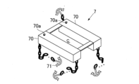
図1に示すように、この実施例の水素製造/貯蔵システム1は、水力駆動装置2と発電装置3と取付体4と水素製造船5とを備えている。
Example 1
FIG. 1 is a perspective view showing a hydrogen production/storage system according to a first embodiment of the present invention, FIG. 2 is a side view showing the hydrogen production/storage system, and FIG. 3 is a front view showing the hydrogen production/storage system.
As shown in FIG. 1, the hydrogen production/
水力駆動装置2と発電装置3とは、取付体4に取り付けられており、取付体4は、図2及び図3に示すように、ブラケット10によって、水素製造船5の横側部に固定されている。The
水力駆動装置2は、水流圧に対応した回転力を出力するための装置であり、第2の回転体20Bのシャフト部20bを出力軸としている。
この水力駆動装置2は、図1に示すように、第1の回転体20Aと第2の回転体20Bと無端ベルト21と複数の第1の抵抗部材22と複数の補助回転体20C~20Gとを有しており、これらの部材は取付体4に組み付けられている。
The
As shown in Figure 1, this
図4は、水力駆動装置2と発電装置3と取付体4とを示す分解斜視図であり、図5は、水力駆動装置2と発電装置3とが取付体4に取り付けられた状態を示す側面図であり、図6は、水力駆動装置2と発電装置3とが取付体4に取り付けられた状態を示す平面図である。
図4に示すように、取付体4は、支持板40と基台41とで構成されている。
支持板40は、長方形の格子板であり、1対の軸受部42と1対の軸受部43とが、支持板40の前側(図の左側)及び後側(図の右側)にそれぞれ立設されている。そして、5枚の長板状の橋部44が、支持板40のほぼ中央部に列設されている。
一方、基台41は、上フレーム45と下フレーム46と柱フレーム47とで形成された直方形のフレーム体であり、平面視において、支持板40と同じ大きさの長方形をなす。
図5及び図6に示すように、支持板40は、この基台41の上フレーム45に載置され、図示しないボルトとナットにより、基台41上に固定されている。これにより、支持板40の強度が、基台41によって補強されている。
Figure 4 is an exploded oblique view showing the
As shown in FIG. 4 , the mounting
The
On the other hand, the
5 and 6, the
第1の回転体20Aは、この取付体4の前方端部側に回転自在に取り付けられ、第2の回転体20Bは、その回転中心軸が第1の回転体20Aの回転中心軸と平行になるように、取付体4の後方端部側に回転自在に取り付けられている。
具体的には、図4に示すように、第1の回転体20Aは、回転中心軸としてのシャフト部20aを有し、このシャフト部20aの両端部が、支持板40の1対の軸受部42に回転自在に取り付けられている。また、第2の回転体20Bは、第1の回転体20Aと同形であり、第1の回転体20Aと同様に回転中心軸としてのシャフト部20bを有している。そして、このシャフト部20bの両端部が、1対の軸受部43に回転自在に取り付けられている。
The first
Specifically, as shown in Fig. 4, the first
無端ベルト21は、このような第1の回転体20Aと第2の回転体20Bとに巻き付けられている。
無端ベルト21は、幅広の帯状体であり、多層構造のゴム部材、合成樹脂、金属製チェーンベルト等で形成することができる。この無端ベルト21の表面には、複数の第1の抵抗部材22が、凹状の受圧面部22A(図7参照)を無端ベルト21の長さ方向に向けた状態で、等間隔で立設されている。
The
The
図7は、第1の抵抗部材を示す斜視図であり、図8は、図7の矢視B-B断面図である。
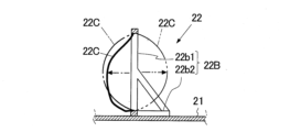
これらの図に示すように、各第1の抵抗部材22は、受圧面部22Aと、この受圧面部22Aを保持する支持部材22Bとによって構成されている。
受圧面部22Aは、水流圧を受けるための部分であり、断面弧状に凹んでいる。受圧面部22Aの長さは、無端ベルト21の幅に対応して設定されている。受圧面部22Aの材質は任意であるが、この実施例では、凹状に湾曲された金属板を適用した。
支持部材22Bは、枠部22b1と、この枠部22b1の両端に形成された固定部22b2,22b2とを有している。枠部22b1は、無端ベルト21の幅方向に沿って配置され、固定部22b2は、無端ベルト21にビス等により固定されている。
そして、受圧面部22Aが枠部22b1内に嵌められ、その上端22a1と下端22a2とが、枠部22b1に固着されている。
FIG. 7 is a perspective view showing the first resistance member, and FIG. 8 is a cross-sectional view taken along line BB of FIG.
As shown in these figures, each of the
The pressure-receiving
The
The pressure-receiving
図4~図6に示すように、複数の補助回転体20C~20Gは、後述する中心軸としてのシャフト部20c~20gを平行にした状態で、第1及び第2の回転体20A,20Bと無端ベルト21の間に配設されている。そして、各補助回転体20C(20D~20G)は、取付体4に取り付けられた油圧ジャッキ6によって上下動自在に支持されている。
As shown in Figures 4 to 6, the multiple
図9は、補助回転体20C(20D~20G)を1対の油圧ジャッキ6によって支持している状態を示す斜視図であり、図10は、油圧ジャッキ6の取付状態を説明するための部分断面図である。
図9に示すように、油圧ジャッキ6は、一般的な周知のジャッキであり、シリンダ61とラム62とで構成されている。シリンダ61内の油圧を、図示しないレバーを操作して調整することにより、ラム62を上下させることができる。
FIG. 9 is a perspective view showing a state in which the
As shown in Fig. 9, the
この実施例では、1対の油圧ジャッキ6が、対向配置され、各補助回転体20C(20D~20G)のシャフト部20c(20d~20g)の両端が、1対の油圧ジャッキ6のラム62の先端部に回動自在に取り付けられている。
図10に示すように、補助回転体20C(20E,20G)を支持する1対の油圧ジャッキ6は、取付体4を構成する支持板40の橋部44に、下向きに取り付けられ、補助回転体20D(20F)を支持する1対の油圧ジャッキ6は、橋部44に、上向きに取り付けられている。
In this embodiment, a pair of
As shown in FIG. 10, a pair of
具体的には、補助回転体20C(20E,20G)を支持する1対の油圧ジャッキ6においては、孔44aが、支持板40の橋部44に開けられ、ラム62が、孔44aに下向きに挿通されると共に、シリンダ61の肩部が、橋部44の上面に固定されている。そして、シャフト部20c(20e,20g)が、橋部44の下側に延出しているラム62の先端部に回動自在に取り付けられている。
一方、補助回転体20D(20F)を支持する1対の油圧ジャッキ6においては、ラム62が上向きにされた状態で、シリンダ61の尻部が、橋部44に固定されている。そして、シャフト部20d(20f)が、上向きのラム62の先端部に回動自在に取り付けられている。
これにより、油圧ジャッキ6のラム62を上下動させることで、無端ベルト21(図5参照)を、各補助回転体20C(20D~20G)によって、部分的に押し上げ又は押し下げることができるようになっている。
Specifically, in a pair of
On the other hand, in the pair of
As a result, by moving the
この実施例では、図5に示すように、全ての油圧ジャッキ6のラム62がシリンダ61内に引き込まれた状態にされ、無端ベルト21の上側ベルト部21Aと下側ベルト部21Bが、補助回転体20C~20Gによって、水平に保持されている。In this embodiment, as shown in Figure 5, the
図11は、無端ベルト21の弛み修正状態を示す側面図である。
図5に示すような状態で、第1及び第2の回転体20A,20Bを長時間稼働させていると、弛みが無端ベルト21に発生する。そのような場合には、図11に示すように、補助回転体20D,20Fの双方又は一方を、油圧ジャッキ6によって上昇させることで、無端ベルト21の弛みを修正することができる。
FIG. 11 is a side view showing the state in which the slack of the
5, if the first and
図12は、第1の回転体20A又は第2の回転体20Bを用いた弛み修正構造の一例を示す部分側面図であり、図13は、第1の回転体20A又は第2の回転体20Bを用いた弛み修正構造の他の例を示す部分側面図である。
無端ベルト21の弛みを修正する技術は、図11に示した技術だけでなく、第1の回転体20A又は第2の回転体20Bに工夫を加えた技術によっても可能である。
例えば、図12の(a)に示すように、軸受部42(又は43)を取付体4の支持板40に回動可能に取り付ける。そして、図12の(b)に示すように、軸受部42(又は43)を回転させて、第1の回転体20A(又は第2の回転体20B)を取付体4の前方側(又は後方側)に動かすことにより、無端ベルト21の弛みを解消することができる。
また、図13の(a)に示すように、軸受部42(又は43)を取付体4の支持板40にスライド可能に取り付ける。そして、図13の(b)に示すように、軸受部42(又は43)をガイド溝40aに沿ってスライドさせて、第1の回転体20A(又は第2の回転体20B)を取付体4の前方側(又は後方側)にスライドさせることにより、無端ベルト21の弛みを解消することができる。
Figure 12 is a partial side view showing an example of a slack correction structure using a first
The technique for correcting the slack in the
For example, as shown in Fig. 12(a), the bearing portion 42 (or 43) is rotatably attached to the
13A, the bearing portion 42 (or 43) is slidably attached to the
図1に示した発電装置3は、水力駆動装置2の出力軸の回転力を受けて発電動作を行う装置である。
具体的には、図4及び図6に示すように、発電装置3は、傘歯車31,32でなるギア機構と発電機30とで構成されており、水力駆動装置2の出力軸としてのシャフト部20bの一方端部が、噛み合った傘歯車31,32を介して発電機30の回転軸30aに連結されている。そして、これらギア機構と発電機30とが、取付体4の上面に組み付けられ固定されている。
The
4 and 6, the
以上のように、水力駆動装置2と発電装置3とが取り付けられた取付体4は、図1及び図3に示したブラケット10により、水素製造船5の横側部に固定されている。
具体的には、図3の囲み破線A内に示すように、ブラケット10は水平な固定部11とU字状のフック部12とを有している。固定部11は、ボルト13とナット14とによって水素製造船5の甲板に固定されている。そして、フック部12は、取付体4の上フレーム45(基台41)に係合されている。
As described above, the mounting
Specifically, as shown within the enclosed broken line A in Fig. 3, the
図14は、取付体4の改良例を示す斜視図である。
図4に示したように、取付体4は、支持板40と基台41とで構成され、基台41は、上フレーム45と下フレーム46と柱フレーム47とで形成された直方形のフレーム体である。
したがって、基台41の側部が開いており、横波が基台41の開口から浸入して、水力駆動装置2が、この横波を強く受ける場合がある。このような場合には、図14に示すように、基台41の柱フレーム47を平板状の防波フレーム47’に変えた取付体4を用いることで、横波を防波フレーム47’によってブロックすることができる。
なお、防波フレーム47’は、基台41の両側面でなく、一方の側面のみに設けても良い。
FIG. 14 is a perspective view showing an improved example of the mounting
As shown in FIG. 4 , the mounting
Therefore, since the side of the
The wave-break frame 47' may be provided on only one side surface of the
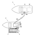
図1において、水素製造船5は、海水から水素を製造して、貯蔵するための船であり、水素製造装置51と水素貯蔵装置52とを船内に備えている。さらに、水素製造船5には、蓄電装置50が搭載されており、発電装置3の発電機30で発電された電気を、この蓄電装置50に蓄電することができるようになっている。
具体的には、蓄電装置50は、交流/直流変換器50aと蓄電池50bとを有しており、発電装置3の発電機30からのケーブル30bを、蓄電装置50の交流/直流変換器50aに接続することができるようになっている。そして、この交流/直流変換器50aの出力部は、蓄電池50bの入力部に電気的に接続されている。
これにより、発電機30によって生成された交流電気が、交流/直流変換器50aによって直流に変換された後、蓄電池50bに蓄電される。
1 , the
Specifically, the
As a result, the AC electricity generated by the
図15は、水素製造船5の水素製造装置51と水素貯蔵装置52とを説明するための概略断面図である。
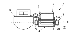
図15に示すように、水素製造装置51は、海水Wから水素H2を製造するための装置であり、海水ポンプ51aと真水(純水)製造器51bと電気分解装置51cとで構成されている。
つまり、海水ポンプ51aが洋上の海水Wを吸い上げ、真水製造器51bがこの吸い上げた海水Wを真水(純水)W’にした後、電気分解装置51c、がこの真水W’を電気分解して、水素H2を取り出す。
水素貯蔵装置52は、水素製造装置51で製造した水素H2を貯蔵するための装置であり、タンク状を成す。水素H2を貯蔵する方法としては、製造した水素H2を高圧化水素法や液化水素法、及び有機ケミカルハイドロイド法等があるが、この実施例では、有機ケミカルハイドロイド法を適用する。
FIG. 15 is a schematic cross-sectional view for explaining the
As shown in FIG. 15, the
That is, a
The
次に、この実施例の水素製造/貯蔵システム1の作用及び効果についてついて説明する。
図1に示すように、水力駆動装置2と発電装置3とが、取付体4に組み付けられ、取付体4がブラケット10を通じて水素製造船5の横側部に固定されているので、水素製造船5を駆動させることにより、水力駆動装置2と発電装置3を遠くの洋上位置まで移動させることができる。
所望の洋上に到達したら、図2に示すように、水素製造船5を当該洋上に停留させる。この際、取付体4の前方側(図2の左方側)を潮流に対向するように、水素製造船5の向きを決定する。
また、取付体4を海水W中に所定深さだけ沈めることによって、水力駆動装置2における無端ベルト21の下側ベルト部21Bに位置する複数の第1の抵抗部材22を海水W中に完没させることができる。
ところで、第1の回転体20Aのシャフト部20aと第2の回転体20Bのシャフト部20bが、海水W中に位置すると、第1及び第2の回転体20A,20Bが海水Wの波を被り、その円滑な回転が阻害される。したがって、第1の回転体20Aのシャフト部20aと第2の回転体20Bのシャフト部20bが、海面Sの上方に位置するように、取付体4の沈み深さを設定する。
このような取付体4の沈み深さの設定は、水素製造船5が出航する前に予め行っておくことができる。勿論、かかる設定を出航前には行わず、所望の洋上に到達した後、行っても良い。
Next, the operation and effects of the hydrogen production/
As shown in FIG. 1, the
When the
Furthermore, by submerging the mounting
However, if the
Such a setting of the sinking depth of the mounting
このような状態で、水素製造船5を停留させておくと、海水Wが取付体4の前方側から後方側に向かって流れるので、水流圧が、下側ベルト部21Bにある複数の第1の抵抗部材22に加わる。これにより、無端ベルト21が巻き付けられた第1の回転体20Aと第2の回転体20Bとが、潮流方向に回転する。そして、その回転力は、水力駆動装置2の出力軸であるシャフト部20bから出力し、傘歯車31,32でなるギア機構(図4及び図6参照)を介して発電装置3の発電機30に伝わる。
この結果、発電機30が発電動作し、発電された交流電流が、図1に示すケーブル30bを通じて水素製造船5の蓄電装置50に伝わる。そして、この交流電流が、交流/直流変換器50aによって、直流電流に変換された後、蓄電池50bに蓄電される。
If the
As a result, the
水素製造船5の蓄電池50bに蓄電された電気は、水素製造装置51と水素貯蔵装置52の動力として活用することができる。また、 水素製造船5の動力に電気を用いている場合には、蓄電された電気をその動力として用いることができる。
つまり、電気を蓄電池50bから水素製造装置51に供給することにより、水素製造装置51の海水ポンプ51aが海水Wを吸い上げ、真水製造器51bが海水Wを真水W’した後、電気分解装置51cが水素H2を真水W’から抽出する。
そして、電気を蓄電池50bから水素貯蔵装置52に供給することにより、水素製造装置51で製造された水素H2が図示しないタンク内に貯蔵される。
水素貯蔵装置52への貯蔵が完了したときは、水素製造船5を駆動させて、貯蔵した水素H2を陸上の水素供給所まで輸送する。
The electricity stored in the
In other words, by supplying electricity from the
Then, by supplying electricity from the
When storage in the
また、発電作業中に、流れが弱まった場合等、潮流に変化が生じた場合には、水素製造船5を再駆動させて、所望強さの潮流が生じている洋上まで移動する。そして、水素製造船5を当該洋上に再度停留させることで、水素の製造/貯蔵作業を行うことができる。
In addition, if a change occurs in the tidal current, such as if the current weakens during power generation operations, the
以上のように、この実施例の水素製造/貯蔵システム1によれば、水素製造船5で移動可能な場所ならば、水素製造及び水素貯蔵作業をいかなる場所でも行うことができる。したがって、季節で変化する潮流の流れの変化に対応して、水素製造船5を最適の場所に移動させ、水素製造及び水素貯蔵作業を行うことができるので、従来の風力を利用して発電するシステムと比べて、水素製造及び水素貯蔵を安定的に行うことができる。As described above, according to the hydrogen production/
なお、上記したように、水素製造/貯蔵システム1による水素製造及び水素貯蔵作業は、水素製造船5を所望の洋上で停留させた状態で行うのが通常である。
しかし、水力駆動装置2と発電装置3によって発電した電気又は蓄電装置50に蓄えてある電気を、水素製造船5の水素製造装置51と水素貯蔵装置52とに供給することで、水素製造船5を運航させながら、同時に、水素製造及び水素貯蔵作業も行うことができる。
As described above, hydrogen production and storage operations by the hydrogen production/
However, by supplying electricity generated by the
(実施例2)
次に、この発明の第2実施例について説明する。
図16は、この発明の第2実施例に係る水素製造/貯蔵システムに適用される水素製造船5の概略断面図である。
図16に示すように、この実施例に適用される水素製造船5は、蓄電装置50が搭載されていない。
すなわち、コネクタ50cが水素製造船5上に設けられ、発電装置3の発電機30からのケーブル30b(図1参照)がこのコネクタ50cの入力端に電気的に接続されている。そして、コネクタ50cの出力端が、配線50dを通じて、水素製造装置51や水素貯蔵装置52に電気的に接続されている。
これにより、発電装置3の発電機30で発電された交流電流を、図1に示すケーブル30bとコネクタ50cと交流/直流変換器50aとを通じて水素製造船5の水素製造装置51と水素貯蔵装置52とに直接供給することができる。
その他の構成作用及び効果は、上記第1実施例と同様であるので、その記載は省略する。
Example 2
Next, a second embodiment of the present invention will be described.
FIG. 16 is a schematic cross-sectional view of a
As shown in FIG. 16, the
That is, a
This allows the AC generated by the
The other configurations, functions and effects are the same as those of the first embodiment, and therefore the description thereof will be omitted.
(実施例3)
次に、この発明の第3実施例について説明する。
図17は、この発明の第3実施例に係る水素製造/貯蔵システムに適用される水素製造船5の概略断面図である。
図17に示すように、この実施例に適用される水素製造船5は、コネクタ50cと蓄電装置50との双方を搭載している。
すなわち、ケーブル30bが発電装置3の発電機30から2対引き出され、一方のケーブル30bがコネクタ50cの入力端に電気的に接続されると共に、他方のケーブル30bが蓄電装置50に電気的に接続されている。
これにより、発電装置3の発電機30で発電された交流電流を、図1に示すケーブル30bとコネクタ50cと交流/直流変換器50aとを通じて水素製造船5の水素製造装置51と水素貯蔵装置52とに直接供給することができると同時に、蓄電装置50の交流/直流変換器50aを通じて蓄電池50bに蓄電することができる。
その他の構成作用及び効果は、上記第1実施例及び第2実施例と同様であるので、その記載は省略する。
Example 3
Next, a third embodiment of the present invention will be described.
FIG. 17 is a schematic cross-sectional view of a
As shown in FIG. 17, the
That is, two pairs of
As a result, the AC current generated by the
The other configurations, functions and effects are similar to those of the first and second embodiments described above, and therefore the description thereof will be omitted.
(実施例4)
次に、この発明の第4実施例について説明する。
図18は、この発明の第4実施例に係る水素製造/貯蔵システムの要部を示す断面図であり、図19は、この実施例に適用される回転方向変換器を説明するための平面図である。
この実施例では、可撓性構造の第1の抵抗部材22と回転方向変換器3Aとを備えている点が、上記第1実施例と異なる。
Example 4
Next, a fourth embodiment of the present invention will be described.
FIG. 18 is a cross-sectional view showing a main portion of a hydrogen production/storage system according to a fourth embodiment of the present invention, and FIG. 19 is a plan view for explaining a rotational direction changer applied to this embodiment.
This embodiment differs from the first embodiment in that it includes a
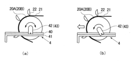
図18に示すように、この実施例に適用される第1の抵抗部材22は、可撓性素材で形成された受圧面部22Cと、受圧面部22Cを支持する支持部材22Bとで構成されている。
受圧面部22Cは、可撓性素材で形成されていれば良く、布製、合成繊維製、合成樹脂性等、その種類は任意である。この実施例では、受圧面部22Cとして、布製のものを適用した。
かかる構成により、水流圧が、一点鎖線で示す矢印方向から実線で示す受圧面部22Cに加わると、受圧面部22Cは、水流圧により一点鎖線で示すように撓んで、ヨットの帆のように、水流圧を受ける。また、水流圧の方向が、二点鎖線で示す方向に変化すると、一点鎖線状態の受圧面部22Cが、二点鎖線で示すように、水流圧方向に撓み、ヨットの帆のように、水流圧を受ける。
As shown in FIG. 18, the
The pressure-receiving
With this configuration, when water flow pressure is applied to the
図19に示すように、回転方向変換器3Aは、水力駆動装置2と発電装置3との間に設けられている。
具体的には、回転方向変換器3Aは、ギア機構の傘歯車32と発電機30の回転軸30aとの間に設けられている。この回転方向変換器3Aは、水力駆動装置2の出力軸20bの回転方向と発電機30の回転軸30aの回転方向とを同一方向又は逆方向に手動で変換することができる機器である。このような回転方向変換器3Aとして、全ての周知の変換器を適用することができるので、ここでは、詳細な説明は省略する。
As shown in FIG. 19 , a
Specifically, the
この実施例に適用される第1の抵抗部材22が、上記構造をとっているので、図2の実線矢印で示すように、潮流方向が右方向の場合には、図18に示したように、第1の抵抗部材22の受圧面部22Cが、水流圧を受けて、右方に撓む。この結果、第1の回転体20Aと第2の回転体20Bと無端ベルト21とが、下側ベルト部21Bの第1の抵抗部材22に加わる水流圧によって反時計回りに回転する。
そして、図2の二点鎖線矢印で示すように、潮流方向が左方向に変わった場合には、第1の抵抗部材22の受圧面部22Cが、水流圧を受けて、左方に撓む。この結果、回転方向変換器3Aが作動すると共に、第1の回転体20Aと第2の回転体20Bと無端ベルト21とが時計回りに回転する。
つまり、この実施例によれば、流れが変化するような場所で使用する場合において、水素製造船5や水力駆動装置2及び発電装置3の向きを潮流方向の変化に合わせて変えることなく、水素製造及び水素貯蔵作業を継続することができる。
その他の構成作用及び効果は、上記第1ないし第3実施例と同様であるので、その記載は省略する。
Since the
2, when the tidal current direction changes to the left, the pressure-receiving
In other words, according to this embodiment, when used in a location where the flow changes, hydrogen production and hydrogen storage operations can be continued without changing the orientation of the
The other configurations, functions and effects are the same as those of the first to third embodiments described above, so the description thereof will be omitted.
(実施例5)
次に、この発明の第5実施例について説明する。
図20は、この発明の第5実施例の要部である第1の抵抗部材を示す斜視図であり、図21は、実施例の動作を説明するための側面図である。
この実施例の水素製造/貯蔵システムでは、水力駆動装置2における第1の抵抗部材の構造が上記第1ないし第4実施例と異なる。
Example 5
Next, a fifth embodiment of the present invention will be described.
FIG. 20 is a perspective view showing a first resistance member which is a main part of a fifth embodiment of the present invention, and FIG. 21 is a side view for explaining the operation of the embodiment.
In the hydrogen production/storage system of this embodiment, the structure of the first resistance member in the
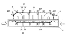
すなわち、図20に示すように、この実施例の第1の抵抗部材22’は、上記第1実施例で適用された第1の抵抗部材22と同構造の抵抗部材23,24を背中合わせで接合した構造になっている。具体的には、図左向きの抵抗部材23の受圧面部22Aと図右向きの抵抗部材24の受圧面部22Aとが、中間部材25を介して背中合わせに接合されている。 That is, as shown in Fig. 20, the first resistance member 22' in this embodiment has a structure in which
第1の抵抗部材22’が、このような構造になっているので、図21に示すように、潮流方向が右方向の場合には、下側ベルト部21Bの第1の抵抗部材22’において、この第1の抵抗部材22’の左側の抵抗部材24が、実線矢印で示す方向の水流圧を受ける。
そして、潮流方向が左方向に変化した場合には、第1の抵抗部材22’の右側の抵抗部材23が、二点鎖線矢印で示す方向の水流圧を受ける。
つまり、流れが変化するような洋上で使用する場合においても、水素製造船5や水力駆動装置2及び発電装置3の向きを潮流方向の変化に合わせて変えることなく、水素製造及び水素貯蔵作業を継続することができる。
その他の構成、作用及び効果は、上記第1ないし第4実施例と同様であるので、それらの記載は省略する。
Because the first resistance member 22' has this structure, when the tidal current direction is to the right, as shown in Figure 21, in the first resistance member 22' of the
When the tidal current direction changes to the left, the
In other words, even when used at sea where the current is changing, hydrogen production and hydrogen storage operations can be continued without changing the orientation of the
The other configurations, operations and effects are the same as those of the first to fourth embodiments described above, and therefore the description thereof will be omitted.
(実施例6)
次に、この発明の第6実施例について説明する。
図22は、この発明の第6実施例に係る水素製造/貯蔵システムの要部を示す側面図である。
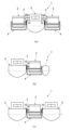
図11に示したように、各補助回転体20C(20D~20G)は、油圧ジャッキ6によって上下動自在に移動させることができるようになっている。したがって、補助回転体20C,20E,20Gのいずれかを下方に移動させることで、無端ベルト21の下側ベルト部21Bを、海水Wの水深方向に略く字状に湾曲させることができる。このように、無端ベルト21の下側ベルト部21Bを、海水Wの水深方向に略く字状に湾曲させることにより、発電量を増加させることができる。
この点に注目して、この実施例では、図22に示すように、水力駆動装置2の補助回転体20C~20Gのうち、最下流に位置する補助回転体20Gを、他の補助回転体20C~20Fよりも下方に位置させた。
具体的には、補助回転体20D,20Fを無端ベルト21の上側ベルト部21Aに接触させると共に、補助回転体20C,20Eを下側ベルト部21Bに接触させた。そして、最下流に位置する補助回転体20Gを、他の補助回転体20C~20Fよりも下側に位置させて固定した。
Example 6
Next, a sixth embodiment of the present invention will be described.
FIG. 22 is a side view showing a main part of a hydrogen production/storage system according to a sixth embodiment of the present invention.
11, each
Taking this into consideration, in this embodiment, as shown in Figure 22, among the
Specifically, the
これにより、下側ベルト部21Bにある各第1の抵抗部材22は、前に位置する他の第1の抵抗部材22の背後に隠れることなく、その下方に位置するので、前の第1の抵抗部材22が受ける水流圧と同じ水流圧受け取ることができる。
つまり、下側ベルト部21Bにある全ての第1の抵抗部材22がそれぞれ同じ水流圧を受けることができるので、水流圧を効率的に確保することができ、極めて大きな電力を発電することができる。
As a result, each
In other words, since all of the
図23は、本実施例の改良例を説明するための要部側面図である。
上記第1実施例等では、図2等で示すように、無端ベルト21の下側ベルト部21Bがほぼ水平になっているので、第1及び第2の回転体20A,20Bの底部を海水W内に沈めた状態しなければ、発電動作を実行することができない。
かかる状態では、第1及び第2の回転体20A,20Bが海面Sに近いため、高波を被って破損するおそれがある。かといって、第1及び第2の回転体20A,20Bが海水Wに触れないように、軸受部42,43を長くして、第1及び第2の回転体20A,20B全体を海面Sから上方に位置させると、下側ベルト部21Bが海面Sの上方に離れた状態になり、発電動作を実行することができない。
これに対して、本実施例に適用される水力駆動装置2では、下側ベルト部21Bが海水Wの水深方向に略く字状に湾曲しているので、図23に示すように、水力駆動装置2の軸受部42,43を長くして、第1及び第2の回転体20A,20B全体を、高波を被らない位置まで海面Sから上方に位置させると共に、下側ベルト部21Bの一部を海水W内に常時沈めた状態に改良することができる。
これにより、高波による第1及び第2の回転体20A,20Bの破損を回避しながら、発電動作を実行継続することができる。
その他の構成,作用及び効果は上記第1実施例ないし第5実施例と同様であるので、それらの記載は省略する。
FIG. 23 is a side view of a main portion for explaining an improved example of this embodiment.
In the above-mentioned first embodiment, etc., as shown in Figure 2, etc., the
In this state, the first and second
In contrast, in the
This makes it possible to continue power generation operation while avoiding damage to the first and second
The other configurations, operations and effects are the same as those of the first to fifth embodiments, and therefore the description thereof will be omitted.
(実施例7)
次に、この発明の第7実施例について説明する。
図24は、この発明の第7実施例に係る水素製造/貯蔵システムの要部を示す側面図である。
図24に示すように、この実施例では、複数の補助回転体20C~20Gのうち略中央に位置する補助回転体20Eを、他の補助回転体20C,20D,20F,20Gよりも下方に位置させた。
(Example 7)
Next, a seventh embodiment of the present invention will be described.
FIG. 24 is a side view showing a main part of a hydrogen production/storage system according to a seventh embodiment of the present invention.
As shown in FIG. 24, in this embodiment, an
具体的には、無端ベルト21の上側ベルト部21Aが、補助回転体20D,20Fによって水平に支持されている。そして、下側ベルト部21Bが、中央に位置する最下位の補助回転体20Eによってくの字状に湾曲され、補助回転体20C,20Gが、下側ベルト部21Bの内面に当接されている。
なお、この実施例では、理解を容易にするため、奇数個の補助回転体20C~20Gを、複数の補助回転体として適用した例を示すが、補助回転体の数は、奇数に限定されない。偶数の補助回転体を適用して、そのほぼ中央の補助回転体を最下位に位置決めした構造のものも、この発明の水力駆動装置2として適用することができる。
Specifically, the
In this embodiment, for ease of understanding, an odd number of
また、この実施例では、第1の抵抗部材として、可撓性の受圧面部22Cを有した第4実施例の第1の抵抗部材22(図18参照)を適用すると共に、回転方向変換器3A(図19参照)を、水力駆動装置2と発電装置3との間に設けた。
但し、第1の抵抗部材として、受圧面部が背中合わせの第5実施例の第1の抵抗部材22’(図21参照)を適用することもできる。
In this embodiment, the first resistance member 22 (see Figure 18) of the fourth embodiment having a flexible pressure-receiving
However, as the first resistance member, the first resistance member 22' (see FIG. 21) of the fifth embodiment in which the pressure receiving surfaces are back-to-back may also be used.
この実施例の水力駆動装置2が、かかる構成をとることにより、図24の実線矢印で示すように、潮流方向が右方向の場合には、補助回転体20Eよりも左側に位置する第1の抵抗部材22の受圧面部22Cが、水流圧を受けて、右方に撓み、第1の回転体20Aと第2の回転体20Bと無端ベルト21とが、水流圧によって反時計回りに回転する。
そして、二点鎖線矢印で示すように、潮流方向が左方向に変わった場合には、補助回転体20Eよりも右側に位置する第1の抵抗部材22の受圧面部22Cが、水流圧を受けて、左方に撓む。この結果、回転方向変換器3Aが作動すると共に、第1の回転体20Aと第2の回転体20Bと無端ベルト21とが時計回りに回転する。
したがって、この実施例によれば、第4実施例や第5実施例のシステムと同様に、流れが変化するような場所でも、装置を動かすことなく、発電及び蓄電作業を継続することができる。
As a result of the
When the tidal current direction changes to the left as shown by the two-dot chain arrow, the pressure-receiving
Therefore, according to this embodiment, like the systems of the fourth and fifth embodiments, even in places where the flow changes, it is possible to continue power generation and storage operations without moving the device.
ところで、第4実施例(又は第5実施例)においては、無端ベルト21の下側ベルト部21Bが水平になっているため、下側ベルト部21Bにある複数の第1の抵抗部材22(22’)が横一列に並んで、水流圧を受けることになる。このため、水流圧を100%受けることができるのは、最初の第1の抵抗部材22(22’)だけであり、その背後に位置する多数の第1の抵抗部材22(22’)が受けることができる水流圧は、お互いの干渉によって、非常に少なくなる。
これに対して、この実施例では、水流圧を受けることができる第1の抵抗部材22(22’)は、補助回転体20Eの片側に位置する第1の抵抗部材22(22’)であり、その数は、下側ベルト部21Bにある第1の抵抗部材22(22’)の数の半数である。しかし、これら第1の抵抗部材22(22’)は、横一列でなく、互いに干渉しないように、その位置が互いに水深方向にずれているので、各第1の抵抗部材22(22’)は100%の水流圧を受けることができる。
したがって、この実施例では、水流圧を受ける第1の抵抗部材22の数が第4実施例(第5実施例)における第1の抵抗部材22(22’)よりも少ないものの、その発電能力は第4実施例(第5実施例)における発電能力よりも大きいと解される。
In the fourth embodiment (or fifth embodiment), the
In contrast, in this embodiment, the first resistance members 22 (22') that can receive the water flow pressure are the first resistance members 22 (22') located on one side of the
Therefore, in this embodiment, although the number of
図25は、この実施例の改良例を示す要部側面図である。
上記第6実施例の改良例と同様に、本実施例においても、図25に示すように、水力駆動装置2の軸受部42,43を長くして、第1及び第2の回転体20A,20B全体を、高波を被らない位置まで海面Sから上方に位置させると共に、下側ベルト部21Bの一部を海水W内に常時沈めた状態の構造に改良することができる。
これにより、高波による第1及び第2の回転体20A,20Bの破損を回避しながら、発電を継続することができる。
その他の構成、作用及び効果は、上記第1実施例ないし第6実施例と同様であるので、それらの記載は省略する。
FIG. 25 is a side view of the essential part showing an improved example of this embodiment.
As in the improved example of the sixth embodiment described above, in this embodiment too, as shown in FIG. 25, the bearing
This makes it possible to continue generating power while avoiding damage to the first and second
The other configurations, operations and effects are similar to those of the first to sixth embodiments, and therefore the description thereof will be omitted.
(実施例8)
次に、この発明の第8実施例について説明する。
図26は、この発明の第8実施例に係る水素製造/貯蔵システムを示す正面図であり、図27は、浮体具の斜視図である。
図26に示すように、この実施例の水力発電/蓄電システム1では、水力駆動装置2と発電装置3とが取り付けられた取付体4が、水素製造船5とは別体の浮体具7に取り付けられている。
(Example 8)
Next, an eighth embodiment of the present invention will be described.
FIG. 26 is a front view showing a hydrogen production/storage system according to an eighth embodiment of the present invention, and FIG. 27 is a perspective view of a floating device.
As shown in FIG. 26 , in the hydroelectric power generation/
具体的には、図27に示すように、浮体具7は、矩形状に組み立てられた1対のタンク70とアンカ71とで構成されている。水力駆動装置2及び発電装置3が取り付けられた取付体4は、図26に示すように、この浮体具7の取付口C内に嵌め込まれ、タンク70内の空気によって洋上に浮かされている。Specifically, as shown in Fig. 27, the floating
かかる構成により、浮体具7に取り付けられた取付体4を、水素製造船5によって、所望の洋上位置まで曳航し、アンカ71を用いてタンク70を係留させることで、水力駆動装置2及び発電装置3を有する取付体4を洋上に固定することができる。
海面Sに対する沈み深さは、蓋70aを開けて、海水Wをタンク70内に注入又はタンク70内の海水Wを排出することにより、設定することができる。
これにより、必要なときに、水素製造船5だけを、陸上の水素供給所等に帰航させることができる。
また、潮流の方向等の変化が激しい洋上で作業する場合においても、大きな水素製造船5の向きを変化させる必要がない。つまり、取付体4が設けられた浮体具7だけを、潮流の方向に合わせるだけで、容易に対応することができる。
その他の構成作用及び効果は、上記第1ないし第7実施例と同様であるので、その記載は省略する。
With this configuration, the mounting
The sinking depth relative to the sea surface S can be set by opening the
This allows the
Furthermore, even when working on the ocean where the direction of the tidal current changes drastically, there is no need to change the orientation of the large
The other configurations, functions and effects are the same as those of the first to seventh embodiments, and therefore the description thereof will be omitted.
(実施例9)
次に、この発明の第9実施例について説明する。
図28は、この発明の第9実施例に係る水素製造/貯蔵システムを示す正面図であり、図29は、水素製造/貯蔵システムを示す平面図である。
この実施例では、浮体具として、蓄電船5’を用いた点で、上記第8実施例と異なる。
すなわち、図28及び図29に示すように、水力駆動装置2と発電装置3とが取り付けられた取付体4が、ブラケット10を介して、水素製造船5とは別体の浮体具としての蓄電船5’に取り付けられている。
そして、発電装置3からのケーブル30bが、蓄電船5’の蓄電装置50に接続され、蓄電装置50からの長いケーブル30b’が水素製造船5のコネクタ50cに接続されている。コネクタ50cからの配線50dは、水素製造装置51と水素貯蔵装置52とにそれぞれ接続されている。
(Example 9)
Next, a ninth embodiment of the present invention will be described.
FIG. 28 is a front view showing a hydrogen production/storage system according to a ninth embodiment of the present invention, and FIG. 29 is a plan view showing the hydrogen production/storage system.
This embodiment differs from the eighth embodiment in that an electricity storage ship 5' is used as the floating structure.
That is, as shown in Figures 28 and 29, a mounting
A
かかる構成により、水素製造船5を陸上の水素供給所の近くの洋上に待機させておき、水力駆動装置2と発電装置3とが取り付けられた取付体4だけを、蓄電船5’によって、遠くの沖合まで運ぶことができる。
この結果、沖合で発電した電気を、蓄電船5’の蓄電装置50とケーブル30b’を通じて、水素供給所近くの水素製造船5に供給することができるので、水素を安全且つ安定的に製造、貯蔵して、水素供給所に容易に供給することができる。
With this configuration, the
As a result, electricity generated offshore can be supplied to the
なお、この実施例では、蓄電船5’からの電気を水素製造船5のコネクタ50cで受けて、水素製造装置51と水素貯蔵装置52とに供給する構成としたが、これに限定されない。蓄電装置50を水素製造船5にも設けて、蓄電船5’からの電気を水素製造船5の蓄電装置50に蓄電し、この蓄電装置50に蓄電された電気を、水素製造装置51と水素貯蔵装置52とに供給する構成とすることもできる。
その他の構成作用及び効果は、上記第1ないし第8実施例と同様であるので、その記載は省略する。
In this embodiment, the electricity from the electricity storage ship 5' is received by the
The other configurations, functions and effects are the same as those of the first to eighth embodiments described above, so the description thereof will be omitted.
(実施例10)
次に、この発明の第10実施例について説明する。
図30は、この発明の第10実施例に係る水素製造/貯蔵システムを示す正面図であり、図30の(a)は、取付体4を2基備えたシステムを示し、図30の(b)は、補助具を備えたシステムを示し、図30の(c)は、水素製造船5を2艘備えたシステムを示す。
(Example 10)
Next, a tenth embodiment of the present invention will be described.
Figure 30 is a front view showing a hydrogen production/storage system according to a tenth embodiment of the present invention, where (a) of Figure 30 shows a system equipped with two mounting
上記第1ないし第9実施例では、水力駆動装置2及び発電装置3を有する取付体4を、水素製造船5の横側部に取り付けた構成になっているので、海面Sの状況によっては、取付体4の安定した姿勢が崩されるおそれがある。
そこで、この実施例では、取付体4の安定した姿勢を確保することができる水素製造/貯蔵システムの構成を例示する。
In the above first to ninth embodiments, the mounting
In this embodiment, therefore, a configuration of a hydrogen production/storage system capable of ensuring a stable posture of the mounting
まず、図30の(a)に示すように、同じ構造の2基の取付体4を、ブラケット10を介して水素製造船5の両側に取り付けることで、水力駆動装置2及び発電装置3を有する取付体4の安定性を確保することができる。このとき、ケーブル30bを、2基の取付体4から水素製造船5の蓄電装置50(又はコネクタ50c)にそれぞれ接続して、大容量の電力を水素製造船5に送ることができるようにしている。First, as shown in (a) of Figure 30, two mounting
また、図30の(b)に示すように、フロート7’を、補助具として、取付体4の横側部に取り付けることで、取付体4の安定性を確保することができる。Furthermore, as shown in (b) of Figure 30, the stability of the mounting
さらに、図30の(c)に示すように、取付体4の両側を、ブラケット10を介して、2艘の水素製造船5にそれぞれ取り付けることで、取付体4の安定性を確保することができると共に、取付体4に取り付けられた水力駆動装置2及び発電装置3を横波から保護することができる。
その他の構成作用及び効果は、上記第1ないし第9実施例と同様であるので、その記載は省略する。
Furthermore, as shown in (c) of Figure 30, by attaching both sides of the mounting
The other configurations, functions and effects are the same as those of the first to ninth embodiments described above, and therefore the description thereof will be omitted.
なお、この発明は、上記実施例に限定されるものではなく、発明の要旨の範囲内において種々の変形や変更が可能である。
例えば、上記実施例では、ブラケット10を用いて、水力駆動装置2及び発電装置3を有する取付体4を水素製造船5に取り付けた例を示したが、取付体4を水素製造船5に設ける構造は、これに限定されるものではなく、公知のあらゆる接合構造を含む。すなわち、ブラケット10を用いずに、溶接やボルトナット等を用いて、取付体4自体を水素製造船5に直接接合する様にしてもよい。この場合には、取付片部を取付体4に形成しておくことが好ましい。
また、上記実施例では、ギア機構を介して、水力駆動装置2の出力軸20bと発電機30の回転軸30aとを連結した例を示したが、水力駆動装置2の出力軸の回転力を発電機30の回転軸に伝える構造は、これに限定されるものではない。ギヤ機構以外の公知のあらゆる機械的機構を用いて、水力駆動装置2の出力軸と発電機30の回転軸とを連結するができる。また、特別な機構を介さずに、水力駆動装置2の出力軸と発電機30の回転軸とを直接連結してもよい。
さらに、上記実施例では、補助回転体20C~20Gを上下動させる昇降装置として、油圧ジャッキ6を用いた例を示したが、これに限定されるものではなく、補助回転体20C~20Gを上下動させることができるあらゆる公知の昇降装置や昇降機構を用いることができる。
It should be noted that the present invention is not limited to the above-described embodiment, and various modifications and variations are possible within the scope of the invention.
For example, in the above embodiment, the mounting
In the above embodiment, the
Furthermore, in the above embodiment, an example is shown in which a
また、上記実施例では、蓄電装置50を水素製造船5や蓄電船5’に設けた例を示したが、小型の蓄電装置50を取付体4に取り付けた構造の水素製造/貯蔵システムも、この発明の範囲に含まれる。
In addition, in the above embodiment, an example was shown in which the
1…水素製造/貯蔵システム、 2…水力駆動置、 3…発電装置、 3A…回転方向変換器、 4…取付体、 5…水素製造船、 5’…蓄電船、 6…油圧ジャッキ、 7…浮体具、 7’…フロート、 10…ブラケット、 11,22b2…固定部、 12…フック部、 13…ボルト、 14…ナット、 20A…第1の回転体、 20B…第2の回転体、 20C~20G…補助回転体、 20a~20g…シャフト部、 21…無端ベルト、 21A…上側ベルト部、 21B…下側ベルト部、 22,22’…第1の抵抗部材、 22A,22C…受圧面部、 22a1…上端、 22a2…下端、 22B…支持部材、 22b1…枠部、 23,24…抵抗部材、 25…中間部材、 30…発電機、 30a…回転軸、 30b,30b’…ケーブル、 31,32…傘歯車、 40…支持板、 40a…ガイド溝、 41…基台、 42,43…軸受部、 44…橋部、 44a…孔、 45…上フレーム、 46…下フレーム、 47…柱フレーム、 47’…防波フレーム、 50…蓄電装置、 51…水素製造装置、 52…水素貯蔵装置、 50a…交流/直流変換器、 50b…蓄電池、 50c…コネクタ、 50d…配線、 51a…海水ポンプ、 51b…真水製造器、 51c…電気分解装置、 61…シリンダ、 62…ラム、 70…タンク、 71…アンカ、 70a…蓋、 W…海水、 S…海面。 1...hydrogen production/storage system, 2...hydraulic drive unit, 3...power generation device, 3A...rotation direction changer, 4...mounting body, 5...hydrogen production ship, 5'...energy storage ship, 6...hydraulic jack, 7...floating device, 7'...float, 10...bracket, 11, 22b2...fixing portion, 12...hook portion, 13...bolt, 14...nut, 20A...first rotating body, 20B...second rotating body, 20C-20G...auxiliary rotating body, 20a-20g...shaft portion, 21...endless belt, 21A...upper belt portion, 21B...lower belt portion, 22, 22'...first resistance member, 22A, 22C...pressure receiving surface portion, 22a1...upper end, 22a2...lower end, 22B...support member, 22b1...frame portion, 23, 24...resistance member, 25...intermediate member, 30...generator, 30a...rotating shaft, 30b, 30b'...cable, 31, 32...bevel gear, 40...support plate, 40a...guide groove, 41...base, 42, 43...bearing portion, 44...bridge portion, 44a...hole, 45...upper frame, 46...lower frame, 47...column frame, 47'...wavebreak frame, 50...electricity storage device, 51...hydrogen production device, 52...hydrogen storage device, 50a...AC/DC converter, 50b...storage battery, 50c...connector, 50d...wiring, 51a...seawater pump, 51b...fresh water production device, 51c...electrolysis device, 61...cylinder, 62...ram, 70...tank, 71...anchor, 70a...cover, W...seawater, S...sea surface.
Claims (10)
上記水力駆動装置は、
上記取付体の一方端部側に回転自在に取り付けられた第1の回転体と、
その回転中心軸が上記第1の回転体の回転中心軸と平行になるように上記取付体の他方端部側に回転自在に取り付けられた第2の回転体と、
上記第1の回転体と第2の回転体とに巻き付けられた無端ベルトと、
各抵抗部材が水流圧を受けるための凹状の受圧面部を有し且つ上記無端ベルトの表面に所定の間隔で立設された複数の第1の抵抗部材と、
その回転中心軸が上記第1及び第2の回転体の回転中心軸と平行な状態で、上記第1の回転体と第2の回転体と無端ベルトとの間に配設され、且つ上記取付体に取り付けられた複数の補助回転体と、を備え、
上記発電装置は、
上記水力駆動装置の出力軸の回転力を回転軸で受けて発電動作を行う発電機を備え、
上記水力駆動装置は、上記第1の回転体及び第2の回転体の少なくとも回転中心軸が水面の上方に位置し、且つ上記無端ベルトのうち第1の回転体及び第2の回転体よりも下側の無端ベルト部分に位置する複数の第1の抵抗部材が水中内に完没するように、上記取付体に取り付けられており、
上記水素製造船は、海水を略真水にした後、当該真水を上記発電装置で発電された電気を用いて電気分解することにより、水素を製造する水素製造装置と、当該水素製造装置で製造した水素を貯蔵する水素貯蔵装置とを備えており、
上記取付体が、上記水素製造船の船体に設けられ、
当該取付体は、上記第1の回転体が上記水素製造船の前方を向くように、水素製造船の横側部に並んで固定され、
上記発電装置で発電された電気を蓄電可能な蓄電装置が、上記水素製造船又は取付体のいずれかに設けられており、
上記蓄電装置に蓄電された電気は、上記水素製造装置と水素貯蔵装置との動力として用いられ、又は上記水素製造船の電気的動力として用いられる、
ことを特徴とする水素製造/貯蔵システム。 A hydrogen production/storage system including a hydraulic drive unit having an output shaft capable of outputting a torque corresponding to a water flow pressure, a power generation unit that generates electricity by receiving the torque of the output shaft, a mounting body to which the hydraulic drive unit and the power generation unit are attached, and a hydrogen production ship capable of producing and storing hydrogen from seawater,
The hydraulic drive device is
A first rotating body rotatably attached to one end side of the mounting body;
a second rotating body rotatably attached to the other end of the attachment body so that the rotation axis of the second rotating body is parallel to the rotation axis of the first rotating body;
an endless belt wound around the first rotating body and the second rotating body;
a plurality of first resistance members provided on the surface of the endless belt at predetermined intervals, each resistance member having a concave pressure-receiving surface portion for receiving water flow pressure;
a plurality of auxiliary rotors, each of which is disposed between the first rotor, the second rotor, and the endless belt with its central axis of rotation parallel to the central axes of rotation of the first and second rotors, and which is attached to the mounting body;
The power generating device is
a generator that generates electricity by receiving the rotational force of the output shaft of the hydraulic drive device at a rotating shaft,
the hydraulic drive device is attached to the mounting body such that at least the central rotation axes of the first and second rotating bodies are located above the water surface, and a plurality of first resistance members located in an endless belt portion of the endless belt below the first and second rotating bodies are completely submerged in water;
The hydrogen production ship includes a hydrogen production device that produces hydrogen by converting seawater into substantially fresh water and then electrolyzing the fresh water using electricity generated by the power generation device, and a hydrogen storage device that stores the hydrogen produced by the hydrogen production device,
the mounting body is provided on a hull of the hydrogen production ship,
the mounting body is fixed next to a lateral side of the hydrogen production ship so that the first rotor faces the front of the hydrogen production ship;
an electricity storage device capable of storing electricity generated by the power generation device is provided in either the hydrogen production ship or the mounting body,
The electricity stored in the power storage device is used to power the hydrogen production device and the hydrogen storage device, or is used as electrical power for the hydrogen production ship.
A hydrogen production/storage system.
上記水力駆動装置は、
上記取付体の一方端部側に回転自在に取り付けられた第1の回転体と、
その回転中心軸が上記第1の回転体の回転中心軸と平行になるように上記取付体の他方端部側に回転自在に取り付けられた第2の回転体と、
上記第1の回転体と第2の回転体とに巻き付けられた無端ベルトと、
各抵抗部材が水流圧を受けるための凹状の受圧面部を有し且つ上記無端ベルトの表面に所定の間隔で立設された複数の第1の抵抗部材と、
その回転中心軸が上記第1及び第2の回転体の回転中心軸と平行な状態で、上記第1の回転体と第2の回転体と無端ベルトとの間に配設され、且つ上記取付体に取り付けられた複数の補助回転体と、を備え、
上記発電装置は、
上記水力駆動装置の出力軸の回転力を回転軸で受けて発電動作を行う発電機を備え、
上記水力駆動装置は、上記第1の回転体及び第2の回転体の少なくとも回転中心軸が水面の上方に位置し、且つ上記無端ベルトのうち第1の回転体及び第2の回転体よりも下側の無端ベルト部分に位置する複数の第1の抵抗部材が水中内に完没するように、上記取付体に取り付けられており、
上記水素製造船は、海水を略真水にした後、当該真水を上記発電装置で発電された電気を用いて電気分解することにより、水素を製造する水素製造装置と、当該水素製造装置で製造した水素を貯蔵する水素貯蔵装置とを備えており、
上記取付体が、上記水素製造船とは別体の浮体具に設けられ、
当該浮体具は、上記水素製造船に固定されることなく、水面上に配置され、
上記発電装置で発電された電気を蓄電可能な蓄電装置が、上記水素製造船又は取付体のいずれかに設けられており、
上記蓄電装置に蓄電された電気は、上記水素製造装置と水素貯蔵装置との動力として用いられ、又は上記水素製造船の電気的動力として用いられる、
ことを特徴とする水素製造/貯蔵システム。 A hydrogen production/storage system including a hydraulic drive unit having an output shaft capable of outputting a torque corresponding to a water flow pressure, a power generation unit that generates electricity by receiving the torque of the output shaft, a mounting body to which the hydraulic drive unit and the power generation unit are attached, and a hydrogen production ship capable of producing and storing hydrogen from seawater,
The hydraulic drive device is
A first rotating body rotatably attached to one end side of the mounting body;
a second rotating body rotatably attached to the other end of the attachment body so that the rotation axis of the second rotating body is parallel to the rotation axis of the first rotating body;
an endless belt wound around the first rotating body and the second rotating body;
a plurality of first resistance members provided on the surface of the endless belt at predetermined intervals, each resistance member having a concave pressure-receiving surface portion for receiving water flow pressure;
a plurality of auxiliary rotors, each of which is disposed between the first rotor, the second rotor, and the endless belt with its central axis of rotation parallel to the central axes of rotation of the first and second rotors, and which is attached to the mounting body;
The power generating device is
a generator that generates electricity by receiving the rotational force of the output shaft of the hydraulic drive device at a rotating shaft,
the hydraulic drive device is attached to the mounting body such that at least the central rotation axes of the first and second rotating bodies are located above the water surface, and a plurality of first resistance members located in an endless belt portion of the endless belt below the first and second rotating bodies are completely submerged in water;
The hydrogen production ship includes a hydrogen production device that produces hydrogen by converting seawater into substantially fresh water and then electrolyzing the fresh water using electricity generated by the power generation device, and a hydrogen storage device that stores the hydrogen produced by the hydrogen production device,
the mounting body is provided on a floating device separate from the hydrogen production ship,
The floating device is placed on the water surface without being fixed to the hydrogen production ship,
an electricity storage device capable of storing electricity generated by the power generation device is provided in either the hydrogen production ship or the mounting body,
The electricity stored in the power storage device is used to power the hydrogen production device and the hydrogen storage device, or is used as electrical power for the hydrogen production ship.
A hydrogen production/storage system.
上記第1の抵抗部材が、可撓性素材で形成された上記受圧面部と、当該受圧面部を上記無端ベルトの表面に起立させて支持する支持部材とで形成されている、
ことを特徴とする水素製造/貯蔵システム。 The hydrogen production/storage system according to claim 1 or 2,
the first resistance member is formed of the pressure-receiving surface portion formed of a flexible material and a support member that supports the pressure-receiving surface portion by standing it up on the surface of the endless belt;
A hydrogen production/storage system.
上記第1の抵抗部材が、互いに背中合わせに接合された1対の上記受圧面部と、これら1対の受圧面部を上記無端ベルトの表面に起立させて支持する支持部材とで形成されている、
ことを特徴とする水素製造/貯蔵システム。 The hydrogen production/storage system according to claim 1 or 2,
the first resistance member is formed of a pair of the pressure-receiving surface portions joined back to back to each other, and a support member that supports the pair of pressure-receiving surface portions by standing them up on the surface of the endless belt;
A hydrogen production/storage system.
上記水力駆動装置の出力軸と発電機の回転軸との間に、水力駆動装置の出力軸の回転方向に対する発電機の回転軸の回転方向を同一方向又は逆方向に変換可能な回転方向変換器を設けた、
ことを特徴とする水素製造/貯蔵システム。 4. The hydrogen production/storage system according to claim 3 ,
A rotation direction converter is provided between the output shaft of the hydraulic drive device and the rotating shaft of the generator, capable of converting the rotation direction of the rotating shaft of the generator to the same direction or the opposite direction with respect to the rotation direction of the output shaft of the hydraulic drive device.
A hydrogen production/storage system.
上記水力駆動装置の出力軸と発電機の回転軸との間に、水力駆動装置の出力軸の回転方向に対する発電機の回転軸の回転方向を同一方向又は逆方向に変換可能な回転方向変換器を設けた、
ことを特徴とする水素製造/貯蔵システム。 5. The hydrogen production/storage system according to claim 4 ,
A rotation direction converter is provided between the output shaft of the hydraulic drive device and the rotating shaft of the generator, capable of converting the rotation direction of the rotating shaft of the generator to the same direction or the opposite direction with respect to the rotation direction of the output shaft of the hydraulic drive device.
A hydrogen production/storage system.
上記複数の補助回転体の中の1つ以上の補助回転体が、他の補助回転体よりも下方に位置決めされて、上記無端ベルトの上記下側の無端ベルト部分が、水深方向に略くの字状に湾曲している、
ことを特徴とする水素製造/貯蔵システム。 The hydrogen production/storage system according to claim 1 or 2,
One or more of the auxiliary rotors among the plurality of auxiliary rotors are positioned lower than the other auxiliary rotors, and the lower endless belt portion of the endless belt is curved in a substantially dogleg shape in the water depth direction.
A hydrogen production/storage system.
上記複数の補助回転体のうち最下流に位置する補助回転体が、他の補助回転体よりも下方に位置されている、
ことを特徴とする水素製造/貯蔵システム。 8. The hydrogen production/storage system according to claim 7 ,
The auxiliary rotor located at the most downstream of the plurality of auxiliary rotors is located lower than the other auxiliary rotors.
A hydrogen production/storage system.
上記複数の補助回転体のうち略中央に位置する補助回転体が、他の補助回転体よりも下方に位置されている、
ことを特徴とする水素製造/貯蔵システム。 8. The hydrogen production/storage system according to claim 7 ,
Among the plurality of auxiliary rotors, an auxiliary rotor located approximately at the center is located lower than the other auxiliary rotors.
A hydrogen production/storage system.
上記複数の補助回転体は、上記取付体に上下動自在に取り付けられている、
ことを特徴とする水素製造/貯蔵システム。 The hydrogen production/storage system according to claim 1 or 2,
The plurality of auxiliary rotating bodies are attached to the mounting body so as to be movable up and down.
A hydrogen production/storage system.
Applications Claiming Priority (3)
| Application Number | Priority Date | Filing Date | Title |
|---|---|---|---|
| JP2023079617 | 2023-05-12 | ||
| JP2023079617 | 2023-05-12 | ||
| PCT/JP2024/016912 WO2024237124A1 (en) | 2023-05-12 | 2024-05-02 | Hydrogen production and storage system |
Publications (2)
| Publication Number | Publication Date |
|---|---|
| JPWO2024237124A1 JPWO2024237124A1 (en) | 2024-11-21 |
| JP7679155B2 true JP7679155B2 (en) | 2025-05-19 |
Family
ID=93519112
Family Applications (1)
| Application Number | Title | Priority Date | Filing Date |
|---|---|---|---|
| JP2024574689A Active JP7679155B2 (en) | 2023-05-12 | 2024-05-02 | Hydrogen Production/Storage System |
Country Status (2)
| Country | Link |
|---|---|
| JP (1) | JP7679155B2 (en) |
| WO (1) | WO2024237124A1 (en) |
Families Citing this family (1)
| Publication number | Priority date | Publication date | Assignee | Title |
|---|---|---|---|---|
| JP2025124388A (en) * | 2024-02-14 | 2025-08-26 | トヨタ自動車株式会社 | Power Storage System |
Citations (10)
| Publication number | Priority date | Publication date | Assignee | Title |
|---|---|---|---|---|
| JP2002127988A (en) | 2000-10-26 | 2002-05-09 | Yuji Takemoto | Submarine boat for ocean current power generation |
| JP2003040190A (en) | 2001-07-27 | 2003-02-13 | Akihiko Kubota | Electrolysis hydrogen producing method in vessel utilizing tide, and vessel for the same |
| JP2005280581A (en) | 2004-03-30 | 2005-10-13 | Toshiba Corp | Aquatic power generating system and aquatic power generation method |
| JP2006177264A (en) | 2004-12-22 | 2006-07-06 | Sumitomo Electric Ind Ltd | Hydrogen supply system |
| WO2011048981A1 (en) | 2009-10-22 | 2011-04-28 | 学校法人中央大学 | Large-scale ocean mobile solar power generation system |
| JP2016100970A (en) | 2014-11-20 | 2016-05-30 | 有限会社板厚計測Bスコープ | Power generation equipment in the sea area that generates power using tidal currents or ocean currents |
| JP2020507714A (en) | 2017-02-20 | 2020-03-12 | スン チェ,オク | Hydroelectric generator using foldable flap |
| JP6894556B1 (en) | 2020-07-14 | 2021-06-30 | 憲郎 東福 | Fluid power generation system and its installation structure |
| JP7174503B1 (en) | 2022-01-14 | 2022-11-17 | 憲郎 東福 | Fluid power generation system and its installation structure |
| US20230086528A1 (en) | 2020-01-27 | 2023-03-23 | Microturbine Consulting Ltd | Hydroelectric generator |
Family Cites Families (2)
| Publication number | Priority date | Publication date | Assignee | Title |
|---|---|---|---|---|
| JPH05256246A (en) * | 1992-03-11 | 1993-10-05 | Hisayoshi Koiwa | On-ship water turbine generating method |
| JPH1088556A (en) * | 1997-05-27 | 1998-04-07 | Mitsuo Kuwano | Kuroshio tidal current power station |
-
2024
- 2024-05-02 JP JP2024574689A patent/JP7679155B2/en active Active
- 2024-05-02 WO PCT/JP2024/016912 patent/WO2024237124A1/en active Pending
Patent Citations (10)
| Publication number | Priority date | Publication date | Assignee | Title |
|---|---|---|---|---|
| JP2002127988A (en) | 2000-10-26 | 2002-05-09 | Yuji Takemoto | Submarine boat for ocean current power generation |
| JP2003040190A (en) | 2001-07-27 | 2003-02-13 | Akihiko Kubota | Electrolysis hydrogen producing method in vessel utilizing tide, and vessel for the same |
| JP2005280581A (en) | 2004-03-30 | 2005-10-13 | Toshiba Corp | Aquatic power generating system and aquatic power generation method |
| JP2006177264A (en) | 2004-12-22 | 2006-07-06 | Sumitomo Electric Ind Ltd | Hydrogen supply system |
| WO2011048981A1 (en) | 2009-10-22 | 2011-04-28 | 学校法人中央大学 | Large-scale ocean mobile solar power generation system |
| JP2016100970A (en) | 2014-11-20 | 2016-05-30 | 有限会社板厚計測Bスコープ | Power generation equipment in the sea area that generates power using tidal currents or ocean currents |
| JP2020507714A (en) | 2017-02-20 | 2020-03-12 | スン チェ,オク | Hydroelectric generator using foldable flap |
| US20230086528A1 (en) | 2020-01-27 | 2023-03-23 | Microturbine Consulting Ltd | Hydroelectric generator |
| JP6894556B1 (en) | 2020-07-14 | 2021-06-30 | 憲郎 東福 | Fluid power generation system and its installation structure |
| JP7174503B1 (en) | 2022-01-14 | 2022-11-17 | 憲郎 東福 | Fluid power generation system and its installation structure |
Also Published As
| Publication number | Publication date |
|---|---|
| JPWO2024237124A1 (en) | 2024-11-21 |
| WO2024237124A1 (en) | 2024-11-21 |
Similar Documents
| Publication | Publication Date | Title |
|---|---|---|
| US10677224B2 (en) | Floating wind power plant | |
| JP5244822B2 (en) | Floating device for generating energy from water streams | |
| US8405242B2 (en) | Wind power system | |
| US7352074B1 (en) | System for producing hydrogen making use of a stream of water | |
| US8558403B2 (en) | Single moored offshore horizontal turbine train | |
| WO2012131621A2 (en) | Wave energy converter with desalination plant | |
| US10422311B2 (en) | Hydroelectricity generating unit capturing marine current energy | |
| JP7730602B2 (en) | Offshore hydrogen charging station | |
| US12270374B2 (en) | Delivery of a high volume of floating systems for wind | |
| JP7679155B2 (en) | Hydrogen Production/Storage System | |
| GB2595521A (en) | Floating vessel with wind turbine support | |
| US8653682B2 (en) | Offshore hydroelectric turbine assembly and method | |
| KR101427564B1 (en) | oxygen and hydrogen supply system with floating offshore combind generator | |
| KR20210105854A (en) | Marine terminal for manufacturing energy suppling to bunkering vessel | |
| CN212580095U (en) | Integral transportation and installation ship for offshore wind turbine | |
| CN117811465A (en) | Floating photovoltaic compressed air energy storage system | |
| JP7576383B2 (en) | Hydroelectric power generation/storage system | |
| CN219237315U (en) | Pile positioning offshore movable wind power platform | |
| CN116443198A (en) | Floating wind power hydrogen production platform system and working method thereof | |
| JP2002127988A (en) | Submarine boat for ocean current power generation | |
| KR102917352B1 (en) | Offshore hydrogen refueling station | |
| CN115626267A (en) | Integral construction method for mooring by pile of floating type offshore wind turbine | |
| CN218594532U (en) | Pile-leaning mooring installation construction structure of floating type offshore wind turbine | |
| JP7312512B1 (en) | power ship | |
| US20240317359A1 (en) | Vessel and system adapted for collection of distant windpower |
Legal Events
| Date | Code | Title | Description |
|---|---|---|---|
| A621 | Written request for application examination |
Free format text: JAPANESE INTERMEDIATE CODE: A621 Effective date: 20241219 |
|
| A871 | Explanation of circumstances concerning accelerated examination |
Free format text: JAPANESE INTERMEDIATE CODE: A871 Effective date: 20241219 |
|
| A131 | Notification of reasons for refusal |
Free format text: JAPANESE INTERMEDIATE CODE: A131 Effective date: 20250205 |
|
| A521 | Request for written amendment filed |
Free format text: JAPANESE INTERMEDIATE CODE: A523 Effective date: 20250322 |
|
| TRDD | Decision of grant or rejection written | ||
| A01 | Written decision to grant a patent or to grant a registration (utility model) |
Free format text: JAPANESE INTERMEDIATE CODE: A01 Effective date: 20250417 |
|
| A61 | First payment of annual fees (during grant procedure) |
Free format text: JAPANESE INTERMEDIATE CODE: A61 Effective date: 20250503 |
|
| R150 | Certificate of patent or registration of utility model |
Ref document number: 7679155 Country of ref document: JP Free format text: JAPANESE INTERMEDIATE CODE: R150 |