JP7678552B2 - Time estimation device and time estimation method - Google Patents
Time estimation device and time estimation method Download PDFInfo
- Publication number
- JP7678552B2 JP7678552B2 JP2021022253A JP2021022253A JP7678552B2 JP 7678552 B2 JP7678552 B2 JP 7678552B2 JP 2021022253 A JP2021022253 A JP 2021022253A JP 2021022253 A JP2021022253 A JP 2021022253A JP 7678552 B2 JP7678552 B2 JP 7678552B2
- Authority
- JP
- Japan
- Prior art keywords
- board
- time
- mounting
- switching
- production
- Prior art date
- Legal status (The legal status is an assumption and is not a legal conclusion. Google has not performed a legal analysis and makes no representation as to the accuracy of the status listed.)
- Active
Links
Images


Classifications
-
- Y—GENERAL TAGGING OF NEW TECHNOLOGICAL DEVELOPMENTS; GENERAL TAGGING OF CROSS-SECTIONAL TECHNOLOGIES SPANNING OVER SEVERAL SECTIONS OF THE IPC; TECHNICAL SUBJECTS COVERED BY FORMER USPC CROSS-REFERENCE ART COLLECTIONS [XRACs] AND DIGESTS
- Y02—TECHNOLOGIES OR APPLICATIONS FOR MITIGATION OR ADAPTATION AGAINST CLIMATE CHANGE
- Y02P—CLIMATE CHANGE MITIGATION TECHNOLOGIES IN THE PRODUCTION OR PROCESSING OF GOODS
- Y02P90/00—Enabling technologies with a potential contribution to greenhouse gas [GHG] emissions mitigation
- Y02P90/02—Total factory control, e.g. smart factories, flexible manufacturing systems [FMS] or integrated manufacturing systems [IMS]
Landscapes
- General Factory Administration (AREA)
- Supply And Installment Of Electrical Components (AREA)
Description
本発明は、部品実装装置による実装基板の生産に要する時間を推定する時間推定装置および時間推定方法に関する。 The present invention relates to a time estimation device and a time estimation method for estimating the time required for a component mounting device to produce a mounted board.
部品実装装置では、段取り作業により部品を供給するフィーダなどが新たな実装基板用と入れ替えられて、複数の種類の実装基板が生産される。従来、部品実装装置における段取り作業や実装基板の生産作業を効率的に行える生産計画を立案するために、段取り時間や総生産時間を予測することが行われている。特許文献1のシステムでは、切り替え前後の部品実装装置に装着されるフィーダの配置情報などから段取り作業の作業量を予測し、各作業に要する時間を積算して段取り時間を予測している。また、特許文献1のシステムでは、部品実装装置に装着されたフィーダの配置情報と部品の残数情報などから生産作業で発生する部品供給作業の発生時刻と作業量を予測して総生産時間を予測している。
In component mounting devices, feeders that supply components are replaced with new ones for new mounting boards through setup work, and multiple types of mounting boards are produced. Conventionally, setup time and total production time have been predicted in order to devise production plans that can efficiently carry out setup work in component mounting devices and production work for mounting boards. In the system of
ところで、特許文献1のシステムでは段取り時間や総生産時間を精度良く予測できる一方で、部品実装装置に装着されるフィーダの配置情報や部品の残数情報などの詳細な情報が必要となるためシミュレーションの事前準備の作業時間と情報量が膨大となる。また、現実の生産現場では予測不可能な作業の発生により段取り時間や総生産時間が変動することがあり、さらに予測不可能な作業の発生は顧客によって異なる傾向もあるため、段取り時間や総生産時間を精度良く推定するためには更なる改善の余地があった。
Meanwhile, while the system in
そこで本発明は、部品実装装置による実装基板の生産に要する時間を実績に基づいて精度良く推定することができる時間推定装置および時間推定方法を提供することを目的とする。 The present invention aims to provide a time estimation device and a time estimation method that can accurately estimate the time required for a component mounting device to produce a mounted board based on past performance.
本発明の時間推定装置は、部品実装装置による実装基板の生産に要する時間を推定する時間推定装置であって、前記部品実装装置において生産する実装基板の種類を切り替える作業に要した段取り時間の実績と、切り替え前の実装基板の基板情報と、切り替え後の実装基板の基板情報とに基づき、学習モデルを生成する学習部と、生成された前記学習モデルを用いて、第1の実装基板の基板情報と第2の実装基板の基板情報から、前記部品実装装置において生産する実装基板を前記第1の実装基板から前記第2の実装基板に切り替える作業に要する段取り時間を推定する段取り時間推定部と、を備え、前記第1の実装基板と前記第2の実装基板との組み合わせが前記切り替え前の前記実装基板と前記切り替え後の実装基板との組み合わせと異なる。 The time estimation device of the present invention is a time estimation device that estimates a time required for production of a mounted board by a component mounting device, and includes: a learning unit that generates a learning model based on an actual result of setup time required for switching the type of mounted board produced by the component mounting device, board information of the mounted board before the switching, and board information of the mounted board after the switching; and a setup time estimation unit that uses the generated learning model to estimate a setup time required for switching the mounted board produced by the component mounting device from the first mounted board to the second mounted board, based on board information of a first mounting board and board information of a second mounting board, wherein a combination of the first mounting board and the second mounting board is different from a combination of the mounting board before the switching and the mounting board after the switching .
本発明の時間推定方法は、部品実装装置による実装基板の生産に要する時間を推定する時間推定方法であって、前記部品実装装置において生産する実装基板の種類を切り替える作業に要した段取り時間の実績と、切り替え前の実装基板の基板情報と、切り替え後の実装基板の基板情報とに基づき、学習モデルを生成する学習工程と、生成された前記学習モデルを用いて、第1の実装基板の基板情報と第2の実装基板の基板情報から、前記部品実装装置において生産する実装基板を前記第1の実装基板から前記第2の実装基板に切り替える作業に要する段取り時間を推定する段取り時間推定工程と、を含み、前記第1の実装基板と前記第2の実装基板との組み合わせが前記切り替え前の前記実装基板と前記切り替え後の実装基板との組み合わせと異なる。 The time estimation method of the present invention is a time estimation method for estimating a time required for production of a mounted board by a component mounting device, and includes: a learning step of generating a learning model based on an actual result of setup time required for switching the type of mounted board produced by the component mounting device, board information of the mounted board before the switching, and board information of the mounted board after the switching; and a setup time estimation step of estimating, using the generated learning model, a setup time required for switching the mounted board produced by the component mounting device from the first mounted board to the second mounted board, based on board information of a first mounting board and board information of a second mounting board, wherein a combination of the first mounting board and the second mounting board is different from a combination of the mounting board before the switching and the mounting board after the switching .
本発明の他の時間推定装置は、部品実装装置による実装基板の生産に要する時間を予測する時間推定装置であって、前記部品実装装置において過去に生産した実装基板の基板情報と生産枚数と総生産時間の実績に基づき、学習モデルを生成する学習部と、生成された前記学習モデルを用いて、前記部品実装装置において生産する前記過去に生産した実装基板と異なる第1の実装基板の基板情報と生産枚数から、前記第1の実装基板の総生産時間を推定する生産時間推定部と、を備えた。 Another time estimation device of the present invention is a time estimation device that predicts a time required for production of a mounted board by a component mounting device, and includes: a learning unit that generates a learning model based on board information, the number of boards produced, and a total production time record of mounted boards previously produced by the component mounting device; and a production time estimation unit that uses the generated learning model to estimate a total production time of a first mounted board that is to be produced by the component mounting device and is different from the previously produced mounted board, from board information and the number of boards produced.
本発明の他の時間推定方法は、部品実装装置による実装基板の生産に要する時間を推定する時間予測方法であって、前記部品実装装置において過去に生産した実装基板の基板情報と生産枚数と総生産時間の実績に基づき、学習モデルを生成する学習工程と、生成された前記学習モデルを用いて、前記部品実装装置において生産する前記過去に生産した実装基板と異なる第1の実装基板の基板情報と生産枚数から、前記第1の実装基板の総生産時間を推定する生産時間推定工程と、を含む。 Another time estimation method of the present invention is a time prediction method for estimating a time required for producing a mounted board by a component mounting device, and includes: a learning step of generating a learning model based on board information, the number of boards produced, and a total production time of a mounted board previously produced by the component mounting device; and a production time estimation step of using the generated learning model to estimate a total production time of a first mounted board, which is to be produced by the component mounting device and is different from the previously produced mounted board, from board information and the number of boards produced.
本発明によれば、部品実装装置による実装基板の生産に要する時間を実績に基づいて精度良く推定することができる。 The present invention makes it possible to accurately estimate the time required to produce a mounted board using a component mounting device based on past performance.
以下に図面を用いて、本発明の一実施の形態を詳細に説明する。以下で述べる構成、形状等は説明のための例示であって、部品実装システム、部品実装ライン、管理コンピュータ、部品実装装置などの仕様に応じ、適宜変更が可能である。以下では、全ての図面において対応する要素には同一符号を付し、重複する説明を省略する。 One embodiment of the present invention will be described in detail below with reference to the drawings. The configurations, shapes, etc. described below are examples for explanatory purposes and can be modified as appropriate depending on the specifications of the component mounting system, component mounting line, management computer, component mounting device, etc. In the following, corresponding elements in all drawings will be given the same reference numerals and duplicated explanations will be omitted.
まず図1を参照して、部品実装システム1の構成を説明する。部品実装システム1は、フロアFに配置された3本の部品実装ラインL1~L3を通信ネットワーク2によって接続し、管理コンピュータ3によって管理する構成となっている。部品実装ラインL1~L3は、フロアFに設けられた生産エリアApに配置されている。各部品実装ラインL1~L3は、後述するようにスクリーン印刷装置、部品実装装置を含む複数の生産設備を連結して構成され、基板に部品を実装した実装基板を生産する機能を有している。なお、部品実装システム1が備える部品実装ラインL1~L3は3本である必要はなく、1本、2本または4本以上でも良い。
First, the configuration of
管理コンピュータ3は、各部品実装ラインL1~L3が備える生産設備の稼働に必要なデータやパラメータを作成し、各生産設備に送信する機能を有している。また、管理コンピュータ3は、部品実装ラインL1~L3の生産設備で使用されるデータやパラメータ、生産実績などに基づいて、部品実装ラインL1~L3においてこれから生産される実装基板の生産に要する時間(段取り時間、総生産時間)を推定する機能を有している。
The
フロアFに設けられた生産エリアApとは異なる準備エリアAsには、配置作業支援装置4が配置されている。配置作業支援装置4は、通信ネットワーク2を介して管理コンピュータ3に接続されている。配置作業支援装置4には、後述する配置作業の対象となる交換用の台車5が接続される。準備エリアAsには、配置作業の実行前、実行中、または実行後など、多様な状態の複数の台車5が保管されている。また、準備エリアAsには、フロアFに配置された生産設備で共用される複数のスクリーンマスク、テープフィーダ、実装ヘッド、吸着ノズル、リールなどの着脱可能な要素が保管されている。
In a preparation area As, which is different from the production area Ap provided on floor F, a placement
図1において、配置作業支援装置4に接続された台車5には、これから部品実装ラインL1~L3において生産される実装基板の種類に対応する作業指示に従った配置作業が行われる。作業者は配置作業として、指示された部品を供給する複数のテープフィーダやリールなどを台車5から外す作業、台車5の指示された位置に取り付ける作業などを実行する。配置作業支援装置4に接続された台車5を含む準備エリアAsにある台車5には、部品実装ラインL1~L3における実装基板の生産と並行して配置作業を実行することができる。以下、台車5に対する配置作業を含む、部品実装ラインL1~L3外での生産する実装基板の種類を切り替えるための準備作業を外段取り作業と称する。
In FIG. 1, a placement operation is performed on a
部品実装ラインL1~L3において生産する実装基板の種類を切り替える際、作業者は準備エリアAsにおいて配置作業が終了した台車5を部品実装ラインL1~L3まで移動させ、部品実装装置に装着されている台車5と交換する台車交換作業を実行する。また切替作業では、作業者は準備エリアAsに保管されている交換用のスクリーンマスク、テープフィーダ、実装ヘッド、吸着ノズル、リールなどを部品実装ラインL1~L3まで移動させて交換する。
When switching the type of mounted boards produced in component mounting lines L1 to L3, workers move the
以下、部品実装ラインL1~L3内での生産する実装基板の種類を切り替えるための準備作業を内段取り作業と称する。すなわち、内段取り作業(実装基板の種類を切り替える作業)には、部品実装装置M3~M6に装着する台車5を入れ替える作業と、部品実装装置M3~M6に装着されている台車5に搭載されるフィーダを入れ替える作業、台車5に搭載されているフィーダが供給する部品を入れ替え・補充する作業と、が含まれている。
Hereinafter, the preparation work for switching the type of mounted board produced within component mounting lines L1 to L3 will be referred to as internal setup work. In other words, internal setup work (the work of switching the type of mounted board) includes the work of switching the
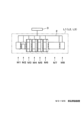
次に図2を参照して、部品実装ラインL1~L3の詳細な構成を説明する。部品実装ラインL1~L3は同様の構成をしており、以下、部品実装ラインL1について説明する。部品実装ラインL1は、基板搬送方向の上流(紙面左側)から下流(紙面右側)に向けて、基板供給装置M1、スクリーン印刷装置M2、部品実装装置M3~M6、リフロー装置M7、基板回収装置M8などの生産設備を直列に連結して構成されている。なお、部品実装ラインL1は通信ネットワーク2を介して接続される生産設備群であって、物理的に生産設備同士が連結されていなくてもよい。
Next, the detailed configuration of component mounting lines L1 to L3 will be described with reference to Figure 2. Component mounting lines L1 to L3 have the same configuration, and below, component mounting line L1 will be described. Component mounting line L1 is configured by connecting production equipment such as board supply device M1, screen printing device M2, component mounting devices M3 to M6, reflow device M7, and board removal device M8 in series from upstream (left side of the paper) to downstream (right side of the paper) in the board transport direction. Note that component mounting line L1 is a group of production equipment connected via
基板供給装置M1、スクリーン印刷装置M2、部品実装装置M3~M6、リフロー装置M7、基板回収装置M8は、通信ネットワーク2を介して管理コンピュータ3に接続されている。基板供給装置M1は、複数の基板を収納するラック等の収納部を備え、収納部から取り出した基板を下流の装置に供給する基板供給作業を実行する。スクリーン印刷装置M2は、印刷作業部に装着されたスクリーンマスクを介して上流側から搬入された基板に半田を印刷する半田印刷作業を実行する。
Board supply device M1, screen printing device M2, component mounting devices M3 to M6, reflow device M7, and board removal device M8 are connected to
部品実装装置M3~M6は、半田が堆積された基板にリールに収納されたキャリアテープをテープフィーダがテープ送りして供給する部品を実装ヘッドに装着された吸着ノズルで取り出して実装する部品実装作業を実行する。なお、部品実装ラインL1は、部品実装装置M3~M6が4台の構成に限定されることなく、部品実装装置M3~M6が1~3台であっても5台以上であってもよい。リフロー装置M7は、装置内に搬入された基板を基板加熱部によって加熱して、基板上の半田を硬化させ、基板の電極部と部品とを接合する基板加熱作業を実行する。基板回収装置M8は、複数の基板を収納するラック等の収納部を備え、上流の装置が搬出する基板を受け取って収納部に回収する基板回収作業を実行する。 The component mounting devices M3 to M6 perform component mounting work by using a tape feeder to feed a carrier tape stored on a reel onto a board on which solder has been deposited, and then using a suction nozzle attached to the mounting head to pick up and mount the components supplied by the tape feeder. Note that the component mounting line L1 is not limited to a configuration of four component mounting devices M3 to M6, and may have one to three component mounting devices M3 to M6, or five or more. The reflow device M7 performs a board heating work in which the board carried into the device is heated by a board heating unit to harden the solder on the board and bond the electrode part of the board to the component. The board recovery device M8 has a storage unit such as a rack that stores multiple boards, and performs a board recovery work in which it receives boards carried out by an upstream device and recovers them in the storage unit.
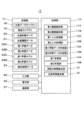
次に図3を参照して、管理コンピュータ3の情報処理系の構成について説明する。ここでは、管理コンピュータ3が備える複数の機能のち、部品実装ラインL1~L3において生産する実装基板を切り替える作業に要する段取り時間、実装基板の総生産時間を推定する機能に関する構成について説明する。すなわち、管理コンピュータ3(時間推定装置)は、部品実装装置M3~M6における段取り時間の実績と切り替え前後の実装基板の基板情報に基づき、これから発生する段取り時間を推定する。また、管理コンピュータ3は、部品実装装置M3~M6において過去に生産した実装基板の基板情報と生産枚数と総生産時間、タクトタイム、稼働率の実績に基づき、新たな実装基板の総生産時間を推定する。
Next, referring to FIG. 3, the configuration of the information processing system of the
管理コンピュータ3は、処理部10、記憶装置である記憶部17の他、入力部25、表示部26、通信部27を備えている。処理部10はCPUなどのデータ処理装置であり、内部処理部として第1履歴解析部11A、第2履歴解析部11B、第1入力処理部12A、第2入力処理部12B、第1学習データ作成部13A、第2学習データ作成部13B、第1学習部14A、第2学習部14B、段取り時間推定部15、生産時間推定部16を備えている。なお、管理コンピュータ3は、ひとつのコンピュータで構成する必要はなく、複数のデバイスで構成してもよい。例えば、記憶部、処理部の全てもしくは一部をサーバを介してクラウドに備えてもよい。
The
図3において、入力部25は、キーボード、タッチパネル、マウスなどの入力装置であり、操作コマンドやデータ入力時などに用いられる。表示部26は液晶パネルなどの表示装置であり、記憶部17が記憶する各種データを表示する他、入力部25による操作のための操作画面、入力画面などの各種情報を表示する。通信部27は、通信インターフェースであり、通信ネットワーク2を介して部品実装ラインL1~L3を構成する生産設備(部品実装装置M3~M6)との間で、生産履歴などのデータの送受信を行う。
In FIG. 3, the
記憶部17には、生産データライブラリ18、部品ライブラリ19、生産計画データ20、生産履歴データ21、第1学習データ22A、第2学習データ22B、第1学習モデル23A、第2学習モデル23B、推定時間データ24などが記憶されている。生産データライブラリ18には、部品実装ラインL1~L3が備える部品実装装置M3~M6による実装基板の生産に使用される生産データが、実装基板の種類(基板種類)毎に記憶されている。
The
ここで図4を参照して、生産データライブラリ18に含まれる生産データ30の例について説明する。生産データライブラリ18には、部品実装ラインL1~L3で過去に生産した実績がある生産データ30の他、これからの生産に使用される生産データ30などが含まれている。生産データライブラリ18に含まれる複数の生産データ30には、それぞれ、1つの種類の実装基板を生産するために必要な基板データBDと設備条件データ35が規定されている。
Now, referring to Figure 4, an example of the
基板データBDには、当該基板種類の実装基板に実装される部品Dの部品名31、当該部品を部品ライブラリ19の部品データと関連付けるための部品コードであるコード32、当該部品の実装基板における実装座標33、実装角度を示す実装角度34が、実装対象の部品名31毎に規定されている。
The board data BD specifies, for each
図4において、設備条件データ35には、部品実装装置M3~M6の種類を示す機種データ、台車5において当該部品が供給される位置を示す供給位置36、部品供給に使用されるフィーダを示すフィーダ37、当該部品を実装する部品実装作業を行う実装ヘッドを示す実装ヘッド38、当該部品の保持に使用されるノズルを示すノズル39などが規定されている。供給位置36は、部品実装装置M3~M6における当該部品を供給するフィーダ37が装着された位置(台車5における装着位置)である。すなわち、設備条件データ35には、当該基板種類の実装基板を生産するための設備情報と部品の配置情報が含まれている。
In FIG. 4, the
このように、生産データ30には、部品実装装置M3~M6において生産される実装基板の基板情報として、基板データBDと設備条件データ35が含まれている。なお、ここに示す例では、生産データ30(基板情報)に設備条件データ35を含めた構成となっているが、設備条件データ35を別ファイルの形で提供する形態であってもよい。
In this way, the
図3において、部品ライブラリ19には、部品の種類と、部品実装装置M3~M6において当該部品を実装する各種の作業を精細に制御するための動作パラメータを関連付けた複数の部品データが記憶されている。部品データは、部品コードによって生産データ30に関連付けられている。生産計画データ20には、部品実装ラインL1~L3で生産予定の実装基板の基板種類、生産枚数、生産順番などが記憶されている。生産履歴データ21には、部品実装ラインL1~L3で生産された実装基板の基板種類、生産した設備情報、部品の配置情報、部品データ、生産枚数、生産開始時刻、生産終了時刻、部品切れエラーなどのエラーの履歴、交換した台車の数やフィーダの数を含む外段取り作業、内段取り作業の履歴などが記憶されている。
In FIG. 3, the
ここで図5を参照して、生産履歴データ21に含まれる段取り時間Tc、総生産時間Tpについて説明する。図5には、部品実装ラインL1~L3で生産された基板種類X1~X8の実装基板の生産に要した時間(段取り時間Tc、総生産時間Tp)が生産時刻に沿った長方形で表示されている。「ラインL1」は部品実装ラインL1を、「ラインL2」は部品実装ラインL2を、「ラインL3」は部品実装ラインL3を表している。
Now, with reference to Figure 5, we will explain the setup time Tc and total production time Tp contained in the
段取り時間Tc(内段取り作業に要した時間)は斜線のハッチング有りの長方形で、総生産時間Tpはハッチング無しの長方形で表示されている。総生産時間Tpを表す長方形の左端が生産開始時刻Ts、右端が生産終了時刻Teである。例えば、部品実装ラインL3では、基板種類X6,X7,X8の実装基板が順に生産されている。基板種類X6の生産終了時刻Teから基板種類X7の生産開始時刻Tsまでの時間が、実装基板の種類を基板種類X6から基板種類X7に切り替える作業に要した段取り時間Tcである。また、基板種類X7の生産開始時刻Tsから生産終了時刻Teまでの時間が、基板種類X7の実装基板の生産に要した総生産時間Tpである。 The setup time Tc (time required for internal setup work) is shown as a hatched rectangle, and the total production time Tp is shown as an unhatched rectangle. The left end of the rectangle representing the total production time Tp is the production start time Ts, and the right end is the production end time Te. For example, on component mounting line L3, mounted boards of board types X6, X7, and X8 are produced in order. The time from the production end time Te of board type X6 to the production start time Ts of board type X7 is the setup time Tc required to switch the type of mounted board from board type X6 to board type X7. The time from the production start time Ts of board type X7 to the production end time Te is the total production time Tp required to produce mounted boards of board type X7.
図3において、第1履歴解析部11Aは、生産履歴データ21(部品実装装置M3~M6の生産履歴)から、後述する第1学習モデル23Aの生成に使用される段取り時間Tcの実績と、切り替え前の実装基板の基板情報(生産データ30)と、切り替え後の実装基板の基板情報を抽出する。第1入力処理部12Aは、作業者が第1学習モデル23Aの生成に使用される段取り時間Tcの実績と、切り替え前の実装基板の基板情報と、切り替え後の実装基板の基板情報を入力するための段取り時間実績入力画面を表示部26に表示させる。作業者は、内段取り作業が終了したタイミングなどに、段取り時間実績入力画面を使用して情報を入力する。なお、段取り時間実績入力画面は、管理コンピュータ3の表示部26の他、作業者が携帯する情報端末に表示するようにしてもよい。
In FIG. 3, the first
ここで図6を参照して、第1入力処理部12Aが表示部26に表示させた段取り時間実績入力画面40の例について説明する。この例では、第1入力処理部12Aは、第1履歴解析部11Aが抽出した情報と生産データライブラリ18の生産データ30(基板情報)に含まれる情報も、参考情報として段取り時間実績入力画面40に表示させている。また、この例では、図5に示す部品実装ラインL3における基板種類X6の実装基板から基板種類X7の実装基板に切り替える段取り時間Tcの実績を入力するための情報が表示されている。
Now, referring to FIG. 6, an example of the setup time
段取り時間実績入力画面40には、生産ライン表示欄41、実績入力枠42、戻るボタン43、確定ボタン44が表示されている。生産ライン表示欄41には、実装基板が生産された部品実装ラインL1~L3を特定する情報が表示される。この例では、部品実装ラインL3を示す「L3」が表示されている。実績入力枠42には、切り替え前枠42a、段取り替え枠42b、切り替え後枠42cが含まれている。切り替え前枠42a、段取り替え枠42b、切り替え後枠42cには、それぞれ第1履歴解析部11Aが抽出した履歴解析結果と、作業者が実績を入力するための入力枠(修正後)が含まれている。
The setup time actual
図6において、切り替え前枠42aには、基板種類(X6)、生産終了時刻Te(2/14 10:24)、使用台車数(8台)、使用フィーダ数(210本)が表示されている。段取り替え枠42bには、段取り時間Tc(3:29)、交換台車数(4台)、交換フィーダ数(105本)が表示されている。切り替え後枠42cには、基板種類(X7)、生産開始時刻Ts(2/14 13:53)、使用台車数(8台)、使用フィーダ数(194本)が表示されている。
In FIG. 6, the
履歴解析結果の段取り時間Tc(3:29)は、段取り替え前の実装基板の生産終了時刻Te(10:24)と段取り替え後の実装基板の生産開始時刻Ts(13:53)から算出された時間である。また、交換フィーダ数は、交換したフィーダの台数、キャリアテープが交換されたフィーダの台数、キャリアテープが補充されたフィーダの台数の合計である。 The setup time Tc (3:29) from the history analysis results is the time calculated from the end time Te (10:24) of the production of the mounted board before the setup change and the start time Ts (13:53) of the production of the mounted board after the setup change. The number of replaced feeders is the sum of the number of replaced feeders, the number of feeders whose carrier tape has been replaced, and the number of feeders whose carrier tape has been replenished.
入力枠の各入力欄には、初期的に履歴解析結果と同じ情報が入力される。作業者は、管理コンピュータ3の入力部25を操作して、各入力欄の情報を変更・入力する。変更された入力欄には、斜線が付されている。この例では、段取り替え枠42bの段取り時間Tcが「2:30」に変更されている。例えば、履歴解析結果から算出された段取り時間Tcに作業者の休憩時間が含まれていた場合には、入力欄の値が休憩時間など内段取り作業を実行していなかった時間を減じた実働時間に修正される。また、段取り替え枠42bの交換フィーダ数が「120本」に変更されている。例えば、履歴解析結果から算出された交換フィーダ数にキャリアテープの補充を行ったフィーダの台数が含まれていなかった場合には、補充を行ったフィーダの台数が加算される。
Initially, the same information as the history analysis result is entered in each input field of the input frame. The worker operates the
図6において、戻るボタン43が操作されると、表示部26の表示画面が前の画面に遷移する。確定ボタン44が操作されると、第1学習モデル23Aの生成に使用される段取り時間Tcの実績などが段取り時間実績入力画面40で修正(入力)された情報に更新される。このように、入力部25は、第1学習モデル23Aの生成に使用される段取り時間Tcの実績と、切り替え前の実装基板の基板情報と、切り替え後の実装基板の基板情報の入力(修正)を受け付ける。段取り時間実績入力画面40を使用して段取り時間Tcの実績などをより正確な数値に修正することで、作成される第1学習モデル23Aの精度を向上させることができる。
In FIG. 6, when the
図3において、第1学習データ作成部13Aは、第1履歴解析部11Aが抽出した情報、または、段取り時間実績入力画面40を使用して入力された情報に基づいて、第1学習部14Aが第1学習モデル23Aを生成する際に使用する第1学習データ22Aを作成する。
In FIG. 3, the first learning
第1学習部14Aは、第1学習データ22Aに含まれる段取り時間Tcの実績と、切り替え前の実装基板の基板情報(設備情報と部品の配置情報を含む生産データ30)と、切り替え後の実装基板の基板情報、部品データを教師データとして、これから生産する実装基板の内段取り作業に要する段取り時間Tcを推定する第1学習モデル23Aを、機械学習等を用いた学習アルゴリズムにより生成する。学習アルゴリズムとしては、ニューラルネットワーク(多層のニューラルネットワークを用いた深層学習を含む)、遺伝的プログラミング、決定木、ベイジアン・ネットワーク、サポート・ベクター・マシン(SVM)等を使用し得る。生成された第1学習モデル23Aは、記憶部17に記憶される。
The
図3において、段取り時間推定部15は、生成された第1学習モデル23Aを用いて、第1の実装基板の基板情報(生産データ30)と第2の実装基板の基板情報から、部品実装装置M3~M6において生産する実装基板を第1の実装基板から第2の実装基板に切り替える作業に要する段取り時間Tc(以下、「推定段取り時間Tce」と称する。)を推定(作成)する。作成された推定段取り時間Tceは、推定時間データ24として記憶部17に記憶される。
In FIG. 3, the setup
なお、推定段取り時間Tceを推定する際に、第1の実装基板と第2の実装基板の設備条件データ35(設備情報、部品の配置情報)、部品データなどが確定している場合は、段取り時間推定部15は、これらの情報も加えて推定段取り時間Tceを推定するようにしてもよい。これにより、推定段取り時間Tceの推定精度を向上させることができる。
When estimating the estimated setup time Tce, if the equipment condition data 35 (equipment information, component placement information), component data, etc. for the first mounting board and the second mounting board are confirmed, the setup
次に図7を参照して、部品実装装置M3~M6による実装基板の生産に要する時間のうち、段取り時間Tcを推定する段取り時間推定処理について説明する。まず、第1学習データ作成部13Aは、生産データライブラリ18、部品ライブラリ19、生産履歴データ21に基づいて、段取り時間Tcの実績と、切り替え前の実装基板の基板情報(生産データ30)と、切り替え後の実装基板の基板情報とを含む、第1学習データ22Aを作成する(ST1:第1学習データ作成工程)。なお、第1学習データ作成部13Aは、第1履歴解析部11Aが抽出した情報、または、作業者が段取り時間実績入力画面40を使用して入力した情報に基づいて、第1学習データ22Aを作成するようにしてもよい。
Next, referring to FIG. 7, a setup time estimation process for estimating setup time Tc from the time required for the production of mounting boards by component mounting devices M3 to M6 will be described. First, the first learning
次いで第1学習部14Aは、第1学習データ22Aに含まれる段取り時間Tcの実績と、切り替え前の実装基板の基板情報と、切り替え後の実装基板の基板情報とに基づき、第1学習モデル23Aを生成する(ST2:第1学習工程)。次いで段取り時間推定部15は、生成された第1学習モデル23Aを用いて、生産データライブラリ18、部品ライブラリ19、生産計画データ20に含まれる、これから部品実装ラインL1~L3で生産される第1の実装基板の基板情報(生産データ30)と第2の実装基板の基板情報から、部品実装装置M3~M6において生産する実装基板を第1の実装基板から第2の実装基板に切り替える作業に要する段取り時間Tc(推定段取り時間Tce)を推定する(ST3:段取り時間推定工程)。
Then, the
具体的には、段取り時間推定部15は、これから生産される第1の実装基板(基板種類X98)と第2の実装基板(基板種類X99)を生産する部品実装装置M3~M6で使用する使用台車数、使用フィーダ数を抽出し、第1の実装基板から第2の実装基板への内段取り作業において交換される台車5とフィーダの数を算出する。そして、段取り時間推定部15は、第1学習モデル23Aを用いて、台車5を入れ替える作業とフィーダを入れ替える作業に要する時間から段取り時間Tcを推定する。
Specifically, the setup
その際、段取り時間推定部15は、第1の実装基板から第2の実装基板に切り替える作業における台車5を入れ替える作業と、フィーダを入れ替える作業の内訳を変更して段取り時間Tcを推定する。推定された推定段取り時間Tceは、推定時間データ24として記憶部17に記憶される。
At that time, the setup
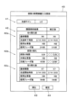
ここで図8を参照して、表示部26に表示された推定段取り時間表示画面45の例について説明する。推定段取り時間表示画面45には、段取り時間推定部15によって推定された推定段取り時間Tceと、推定の前提となった推定条件情報が表示される。推定段取り時間表示画面45には、生産ライン表示欄46、推定条件情報表示枠47、推定段取り時間表示枠48、戻るボタン49、終了ボタン50が表示されている。生産ライン表示欄46には、実装基板を生産する予定の部品実装ラインL1~L3を特定する情報が表示される。この例では、部品実装ラインL2を示す「L2」が表示されている。
Now, referring to FIG. 8, an example of the estimated setup
推定条件情報表示枠47には、切り替え前枠47a、切り替え後枠47bが含まれている。切り替え前枠47a、切り替え後枠47bには、それぞれ基板種類、使用台車数、使用フィーダ数が表示されている。この例では、切り替え前の実装基板は基板種類X98(第1の実装基板)、使用台車数は8台、使用フィーダ数は188本である。また、切り替え後の実装基板は基板種類X99(第2の実装基板)、使用台車数は8台、使用フィーダ数は225本である。
The estimated condition
図8において、推定段取り時間表示枠48には、段取り時間推定部15によって推定された推定結果として、推定段取り時間Tce、交換台車数、交換フィーダ数が表示されている。また、推定段取り時間表示枠48には、推定結果として交換台車数と交換フィーダ数の内訳を変更した推定段取り時間Tceが表示されている。この例では、交換台車数を4台、5台、6台と変更した3つのケースが表示されている。
In FIG. 8, the estimated setup
具体的には、交換台車数が4台の場合は交換フィーダ数が112本で推定段取り時間Tceは2時間25分、交換台車数が5台の場合は交換フィーダ数が98本で推定段取り時間Tceは1時間42分、交換台車数が6台の場合は交換フィーダ数が70本で推定段取り時間Tceは1時間04分である。すなわち、交換台車数が増えると、交換フィーダ数が減少し、推定段取り時間Tceも減少している。交換台車数と交換フィーダ数の内訳を変更した推定段取り時間Tceを推定することで、外段取り作業を含めた最適な生産計画の立案が可能となる。
Specifically, when the number of replacement carts is four, the number of replacement feeders is 112 and the estimated setup time Tce is 2
このように、段取り時間推定部15によって、基板種類X98の実装基板(第1の実装基板)から基板種類X99の実装基板(第2の実装基板)に切り替える作業における台車5を入れ替える作業と、フィーダを入れ替える作業の内訳を変更して推定段取り時間Tceが推定される。戻るボタン49が操作されると、表示部26の表示画面が前の画面に遷移する。終了ボタン50が操作されると、推定段取り時間表示枠48の表示が終了する。
In this way, the setup
次に図9のフローに沿って、部品実装装置M3~M6による実装基板の生産に要する時間のうち、段取り時間Tcを推定する段取り時間推定方法(時間推定方法)について説明する。以下、図7を参照して説明した段取り時間推定処理と同じ工程には同じ符号を付して、詳細な説明は省略する。 Next, a setup time estimation method (time estimation method) for estimating the setup time Tc of the time required for the production of mounted boards by component mounting devices M3 to M6 will be described with reference to the flow in Figure 9. Below, the same steps as those in the setup time estimation process described with reference to Figure 7 are given the same reference numerals, and detailed descriptions will be omitted.
まず、第1履歴解析部11Aは、生産データライブラリ18、部品ライブラリ19、生産履歴データ21(部品実装装置の生産履歴)から、段取り時間Tcの実績と、切り替え前の実装基板の基板情報(生産データ30)と、切り替え後の実装基板の基板情報を抽出する(ST11:第1履歴解析工程)。次いで第1入力処理部12Aが表示部26に段取り時間実績入力画面40を表示させて、作業者による段取り時間Tcの実績と、切り替え前の実装基板の基板情報と、切り替え後の実装基板の基板情報の修正(入力)を受け付ける(ST12:段取り時間実績入力工程)。入力する段取り時間Tcの実績が残っている間は(ST13においてNo)、第1履歴解析工程(ST11)と段取り時間実績入力工程(ST12)が繰り返し実行される。
First, the first
全ての段取り時間Tcの実績が入力されると(ST13においてYes)、第1学習データ作成工程(ST1)が実行されて第1学習データ22Aが作成される。なお、作業者が段取り時間Tcの実績の入力・修正を実行せず、自動で第1学習データ22Aを作成する場合は、段取り時間実績入力工程(ST12)はスキップされる。次いで第1学習工程(ST2)、段取り時間推定工程(ST3)が実行されて、部品実装装置M3~M6において生産する実装基板を第1の実装基板から第2の実装基板に切り替える作業に要する段取り時間Tc(推定段取り時間Tce)が推定される。これによって、部品実装装置M3~M6による実装基板の生産に要する時間(段取り時間Tc)を実績に基づいて精度良く推定することができる。
When all the actual setup times Tc have been input (Yes in ST13), the first learning data creation process (ST1) is executed to create the
上記説明したように、本実施の形態の管理コンピュータ3は、部品実装装置M3~M6において生産する実装基板の種類を切り替える作業に要した段取り時間Tcの実績と、切り替え前の実装基板の基板情報(生産データ30)と、切り替え後の実装基板の基板情報とに基づき、第1学習モデル23Aを生成する第1学習部14Aと、生成された第1学習モデル23Aを用いて、第1の実装基板の基板情報と第2の実装基板の基板情報から、部品実装装置M3~M6において生産する実装基板を第1の実装基板から第2の実装基板に切り替える作業に要する段取り時間Tcを推定する段取り時間推定部15と、を備え、部品実装装置M3~M6による実装基板の生産に要する時間(段取り時間Tc)を推定する時間推定装置である。
As described above, the
図3において、第2履歴解析部11Bは、生産履歴データ21(部品実装装置M3~M6の生産履歴)から、後述する第2学習モデル23Bの生成に使用される過去に生産した実装基板の基板情報(生産データ30)と生産枚数と総生産時間Tpの実績を抽出する。第2入力処理部12Bは、作業者が第2学習モデル23Bの生成に使用される過去に生産した実装基板の基板情報と生産枚数と総生産時間Tp、ラインタクト、稼働率の実績を入力するための総生産時間実績入力画面を表示部26に表示させる。作業者は、実装基板の生産が終了して内段取り作業を開始するタイミングなどに、総生産時間実績入力画面を使用して情報を入力する。なお、総生産時間実績入力画面は、管理コンピュータ3の表示部26の他、作業者が携帯する情報端末に表示するようにしてもよい。
In FIG. 3, the second
ここで図10を参照して、第2入力処理部12Bが表示部26に表示させた総生産時間実績入力画面51の例について説明する。この例では、第2入力処理部12Bは、第2履歴解析部11Bが抽出した情報も、参考情報として総生産時間実績入力画面51に表示させている。また、この例では、図5に示す部品実装ラインL3における基板種類X6の実装基板の総生産時間Tpなどの実績を入力するための情報が表示されている。
Now, referring to FIG. 10, an example of the total production time actual
総生産時間実績入力画面51には、生産ライン表示欄52、実績入力枠53、戻るボタン54、確定ボタン55が表示されている。生産ライン表示欄52には、実装基板が生産された部品実装ラインL1~L3を特定する情報が表示される。この例では、部品実装ラインL3を示す「L3」が表示されている。実績入力枠42には、第2履歴解析部11Bが抽出した履歴解析結果と、作業者が実績を入力するための入力枠(修正後)が含まれている。
The total production time actual
図10において、実績入力枠53には、基板種類(X6)、生産枚数(120枚)、生産開始時刻Ts(2/14 08:10)、生産終了時刻Te(2/14 10:24)、総生産時間Tp(2:14)、ラインタクト(67秒)、稼働率(100%)が表示されている。履歴解析結果の総生産時間Tpは、生産開始時刻Tsと生産終了時刻Teから算出された時間である。ラインタクトは、部品実装装置M3~M6において実装基板を1枚生産するのに要する生産時間である。履歴解析結果のラインタクトは、総生産時間Tpを生産枚数で除して算出される。稼働率は、総生産時間Tpにおいて部品実装装置M3~M6(部品実装ラインL1~L3)が実装基板の生産を実行していた時間の割合である。履歴解析結果の稼働率は、「100%」と仮定されている。
In FIG. 10, the
入力枠の各入力欄には、初期的に履歴解析結果と同じ情報が入力される。作業者は、管理コンピュータ3の入力部25を操作して、各入力欄の情報を変更・入力する。変更された入力欄には、斜線が付されている。この例では、総生産時間Tpが「2:00」、ラインタクトが「60秒」、稼働率が「90%」に変更されている。例えば、履歴解析結果から算出された総生産時間Tpに部品切れで部品実装ラインL3が停止した時間が含まれていた場合には、ライン停止時間を減じた実働時間に修正される。
Each input field in the input frame is initially filled with the same information as the history analysis results. The worker operates the
なお、総生産時間Tp、ラインタクト、稼働率は、作業者がいずれかを修正すると、残りは自動で算出するようにしてもよい。例えば、作業者が総生産時間Tpを修正すると、第2入力処理部12Bが総生産時間Tpと生産枚数からラインタクトを算出し、履歴解析結果の総生産時間Tpと修正された総生産時間Tpから稼働率を算出するようにしてもよい。 In addition, when the worker modifies any of the total production time Tp, line takt, and operation rate, the remaining may be calculated automatically. For example, when the worker modifies the total production time Tp, the second input processing unit 12B may calculate the line takt from the total production time Tp and the number of sheets produced, and may calculate the operation rate from the total production time Tp of the history analysis result and the modified total production time Tp.
戻るボタン54が操作されると、表示部26の表示画面が前の画面に遷移する。確定ボタン55が操作されると、第2学習モデル23Bの生成に使用される総生産時間Tpの実績などが総生産時間実績入力画面51で修正(入力)された情報に更新される。このように、入力部25は、第2学習モデル23Bの生成に使用される過去に生産した実装基板の基板情報と生産枚数と総生産時間Tp、ラインタクト、稼働率の実績の入力(修正)を受け付ける。総生産時間実績入力画面51を使用して総生産時間Tpの実績などをより正確な数値に修正することで、作成される第2学習モデル23Bの精度を向上させることができる。
When the
図3において、第2学習データ作成部13Bは、第2履歴解析部11Bが抽出した情報、または、総生産時間実績入力画面51を使用して入力された情報に基づいて、第2学習部14Bが第2学習モデル23Bを生成する際に使用する第2学習データ22Bを作成する。
In FIG. 3, the second learning
第2学習部14Bは、第2学習データ22Bに含まれる部品実装装置M3~M6において過去に生産した実装基板の基板情報(設備情報と部品の配置情報を含む生産データ30)、部品データと生産枚数と総生産時間Tp、ラインタクト、稼働率の実績を教師データとして、これから生産する実装基板の総生産時間Tpを推定する第2学習モデル23Bを、機械学習等を用いた学習アルゴリズムにより生成する。学習アルゴリズムとしては、ニューラルネットワーク(多層のニューラルネットワークを用いた深層学習を含む)、遺伝的プログラミング、決定木、ベイジアン・ネットワーク、サポート・ベクター・マシン(SVM)等を使用し得る。生成された第2学習モデル23Bは、記憶部17に記憶される。
The
図3において、生産時間推定部16は、生成された第2学習モデル23Bを用いて、部品実装装置M3~M6において生産する第1の実装基板の基板情報(生産データ30)と生産枚数から、第1の実装基板の総生産時間Tp(以下、「推定総生産時間Tpe」と称する。)を推定(作成)する。作成された推定総生産時間Tpeは、推定時間データ24として記憶部17に記憶される。なお、推定総生産時間Tpeを推定する際に、第1の実装基板の設備条件データ35(設備情報、部品の配置情報)、部品データなどが確定している場合は、生産時間推定部16は、これらの情報も加えて、推定総生産時間Tpeを推定するようにしてもよい。これにより、推定総生産時間Tpeの推定精度を向上させることができる。
In FIG. 3, the production
次に図11を参照して、部品実装装置M3~M6による実装基板の生産に要する時間のうち、総生産時間Tpを推定する生産時間推定処理について説明する。まず、第2学習データ作成部13Bは、生産データライブラリ18、部品ライブラリ19、生産履歴データ21に基づいて、部品実装装置M3~M6において過去に生産した実装基板の基板情報と生産枚数と総生産時間Tpの実績とを含む、第2学習データ22Bを作成する(ST21:第2学習データ作成工程)。なお、第2学習データ作成部13Bは、第2履歴解析部11Bが抽出した情報、または、作業者が総生産時間実績入力画面51を使用して入力した情報に基づいて、第2学習データ22Bを作成するようにしてもよい。
Next, referring to FIG. 11, a production time estimation process for estimating the total production time Tp of the time required to produce mounted boards by component mounting devices M3 to M6 will be described. First, the second learning
次いで第2学習部14Bは、第2学習データ22Bに含まれる部品実装装置M3~M6において過去に生産した実装基板の基板情報(生産データ30)と生産枚数と総生産時間Tpの実績に基づき、第2学習モデル23Bを生成する(ST22:第2学習工程)。次いで生産時間推定部16は、生成された第2学習モデル23Bを用いて、生産データライブラリ18、部品ライブラリ19、生産計画データ20に含まれる、これから部品実装装置M3~M6において生産する第1の実装基板の基板情報と生産枚数から、第1の実装基板の総生産時間Tp(推定総生産時間Tpe)を推定する(ST23:生産時間推定工程)。
Then, the
具体的には、生産時間推定部16は、これから生産される第1の実装基板(基板種類X98)の生産枚数と、第2学習モデル23Bを用いて第1の実装基板の基板情報から推定されるラインタクト(部品実装装置M3~M6において実装基板を1枚生産するのに要する生産時間)と、部品実装装置M3~M6の稼働率の少なくともいずれかに基づいて総生産時間Tpを推定する。ラインタクトと稼働率は、類似の実装基板の過去の生産履歴から推定される。推定された推定総生産時間Tpeは、推定時間データ24として記憶部17に記憶される。
Specifically, the production
次に図12のフローに沿って、部品実装装置M3~M6による実装基板の生産に要する時間のうち、総生産時間Tpを推定する生産時間推定方法(時間推定方法)について説明する。以下、図11を参照して説明した生産時間推定処理と同じ工程には同じ符号を付して、詳細な説明は省略する。 Next, a production time estimation method (time estimation method) for estimating the total production time Tp of the time required to produce mounted boards by component mounting devices M3 to M6 will be described with reference to the flow in Figure 12. Below, the same steps as those in the production time estimation process described with reference to Figure 11 are given the same reference numerals, and detailed descriptions will be omitted.
まず、第2履歴解析部11Bは、生産データライブラリ18、部品ライブラリ19、生産履歴データ21(部品実装装置の生産履歴)から、過去に生産した実装基板の基板情報(生産データ30)と生産枚数と総生産時間Tp、ラインタクト、稼働率の実績を抽出する(ST31:第2履歴解析工程)。次いで第2入力処理部12Bが表示部26に総生産時間実績入力画面51を表示させて、作業者による過去に生産した実装基板の基板情報と生産枚数と総生産時間Tp、ラインタクト、稼働率の実績の修正(入力)を受け付ける(ST32:総生産時間実績入力工程)。入力する総生産時間Tpの実績が残っている間は(ST33においてNo)、第2履歴解析工程(ST31)と総生産時間実績入力工程(ST32)が繰り返し実行される。
First, the second
全ての総生産時間Tpの実績が入力されると(ST33においてYes)、第2学習データ作成工程(ST21)が実行されて第2学習データ22Bが作成される。なお、作業者が総生産時間Tpの実績などの入力・修正を実行せず、自動で第2学習データ22Bを作成する場合は、総生産時間実績入力工程(ST32)はスキップされる。次いで第2学習工程(ST22)、生産時間推定工程(ST23)が実行されて、第1の実装基板の総生産時間Tp(推定総生産時間Tpe)が推定される。これによって、部品実装装置M3~M6による実装基板の生産に要する時間(総生産時間Tp)を実績に基づいて精度良く推定することができる。
When all the actual total production times Tp have been input (Yes in ST33), the second learning data creation process (ST21) is executed to create
上記説明したように、本実施の形態の管理コンピュータ3は、部品実装装置M3~M6において過去に生産した実装基板の基板情報(生産データ30)と生産枚数と総生産時間Tpの実績に基づき、第2学習モデル23Bを生成する第2学習部14Bと、生成された第2学習モデル23Bを用いて、部品実装装置M3~M6において生産する第1の実装基板の基板情報と生産枚数から、第1の実装基板の総生産時間Tpを推定する生産時間推定部16と、を備え、部品実装装置M3~M6による実装基板の生産に要する時間(総生産時間Tp)を推定する時間推定装置である。
As described above, the
本発明の時間推定装置および時間推定方法は、部品実装装置による実装基板の生産に要する時間を実績に基づいて精度良く推定することができるという効果を有し、部品を基板に実装する分野において有用である。 The time estimation device and time estimation method of the present invention have the effect of being able to accurately estimate the time required for a component mounting device to produce a mounted board based on past performance, and are useful in fields where components are mounted on boards.
3 管理コンピュータ(時間推定装置)
5 台車
30 生産データ(基板情報)
M3~M6 部品実装装置
Tc 段取り時間
Tp 総生産時間
3. Management computer (time estimation device)
5
M3 to M6 Component mounting equipment Tc Setup time Tp Total production time
Claims (18)
前記部品実装装置において生産する実装基板の種類を切り替える作業に要した段取り時間の実績と、切り替え前の実装基板の基板情報と、切り替え後の実装基板の基板情報とに基づき、学習モデルを生成する学習部と、
生成された前記学習モデルを用いて、第1の実装基板の基板情報と第2の実装基板の基板情報から、前記部品実装装置において生産する実装基板を前記第1の実装基板から前記第2の実装基板に切り替える作業に要する段取り時間を推定する段取り時間推定部と、を備え、
前記第1の実装基板と前記第2の実装基板との組み合わせが前記切り替え前の前記実装基板と前記切り替え後の実装基板との組み合わせと異なる、
時間推定装置。 A time estimation device that estimates a time required for production of a mounted board by a component mounting device,
a learning unit that generates a learning model based on a record of a setup time required for switching the type of mounting board produced by the component mounting device, board information of the mounting board before the switching, and board information of the mounting board after the switching;
a setup time estimation unit that estimates a setup time required for switching a mounting board produced in the component mounting device from the first mounting board to the second mounting board, based on board information of a first mounting board and board information of a second mounting board, using the generated learning model ;
a combination of the first mounting board and the second mounting board is different from a combination of the mounting board before the switching and the mounting board after the switching;
Time estimation device.
前記実装基板の種類を切り替える作業には、前記部品実装装置に装着する台車を入れ替える作業と、前記部品実装装置に装着されている台車に搭載されるフィーダを入れ替える作業と、が含まれ、
前記段取り時間推定部は、前記台車を入れ替える作業と前記フィーダを入れ替える作業に要する時間から前記段取り時間を推定する、請求項1から3のいずれかに記載の時間推定装置。 the component mounting device is capable of mounting a carriage having a plurality of feeders for supplying components;
The operation of switching the type of mounting board includes an operation of replacing a carriage to be attached to the component mounting device, and an operation of replacing a feeder mounted on the carriage attached to the component mounting device,
The time estimation device according to claim 1 , wherein the setup time estimation unit estimates the setup time from a time required for an operation of switching the carriages and an operation of switching the feeders.
前記部品実装装置において生産する実装基板の種類を切り替える作業に要した段取り時間の実績と、切り替え前の実装基板の基板情報と、切り替え後の実装基板の基板情報とに基づき、学習モデルを生成する学習工程と、
生成された前記学習モデルを用いて、第1の実装基板の基板情報と第2の実装基板の基板情報から、前記部品実装装置において生産する実装基板を前記第1の実装基板から前記第2の実装基板に切り替える作業に要する段取り時間を推定する段取り時間推定工程と、を含み、
前記第1の実装基板と前記第2の実装基板との組み合わせが前記切り替え前の前記実装基板と前記切り替え後の実装基板との組み合わせと異なる、
時間推定方法。 A time estimation method for estimating a time required for production of a mounted board by a component mounting apparatus, comprising:
a learning process for generating a learning model based on a record of a setup time required for switching the type of mounting board produced by the component mounting device, board information of the mounting board before the switching, and board information of the mounting board after the switching;
a setup time estimation step of estimating a setup time required for switching a mounting board produced in the component mounting device from the first mounting board to the second mounting board, based on board information of a first mounting board and board information of a second mounting board, using the generated learning model ;
a combination of the first mounting board and the second mounting board is different from a combination of the mounting board before the switching and the mounting board after the switching;
Time estimation method.
前記実装基板の種類を切り替える作業には、前記部品実装装置に装着する台車を入れ替える作業と、前記部品実装装置に装着されている台車に搭載されるフィーダを入れ替える作業と、が含まれ、
前記段取り時間推定工程において、前記台車を入れ替える作業と前記フィーダを入れ替える作業に要する時間から前記段取り時間が推定される、請求項6から8のいずれかに記載の時間推定方法。 the component mounting device is capable of mounting a carriage having a plurality of feeders for supplying components;
The operation of switching the type of mounting board includes an operation of replacing a carriage to be attached to the component mounting device, and an operation of replacing a feeder mounted on the carriage attached to the component mounting device,
9. The time estimation method according to claim 6, wherein in the setup time estimating step, the setup time is estimated from a time required for an operation of switching the carriages and an operation of switching the feeders.
前記部品実装装置において過去に生産した実装基板の基板情報と生産枚数と総生産時間の実績に基づき、学習モデルを生成する学習部と、
生成された前記学習モデルを用いて、前記部品実装装置において生産する前記過去に生産した実装基板と異なる第1の実装基板の基板情報と生産枚数から、前記第1の実装基板の総生産時間を推定する生産時間推定部と、を備えた、時間推定装置。 A time estimation device that predicts a time required for production of a mounted board by a component mounting device,
a learning unit that generates a learning model based on board information, the number of boards produced, and a total production time of boards previously produced by the component mounting device;
and a production time estimation unit that estimates a total production time of a first mounting board, which is to be produced by the component mounting device and differs from the previously produced mounting boards, from board information and a production quantity of the first mounting board, using the generated learning model.
前記部品実装装置において過去に生産した実装基板の基板情報と生産枚数と総生産時間の実績に基づき、学習モデルを生成する学習工程と、
生成された前記学習モデルを用いて、前記部品実装装置において生産する前記過去に生産した実装基板と異なる第1の実装基板の基板情報と生産枚数から、前記第1の実装基板の総生産時間を推定する生産時間推定工程と、を含む、時間推定方法。 A time prediction method for estimating a time required for production of a mounted board by a component mounting device, comprising:
a learning process for generating a learning model based on board information, the number of boards produced, and the total production time of boards previously produced by the component mounting device;
and a production time estimation step of estimating a total production time of a first mounting board, which is to be produced by the component mounting device and is different from the previously produced mounting boards, from board information and a production quantity of the first mounting board, using the generated learning model.
Priority Applications (1)
| Application Number | Priority Date | Filing Date | Title |
|---|---|---|---|
| JP2021022253A JP7678552B2 (en) | 2021-02-16 | 2021-02-16 | Time estimation device and time estimation method |
Applications Claiming Priority (1)
| Application Number | Priority Date | Filing Date | Title |
|---|---|---|---|
| JP2021022253A JP7678552B2 (en) | 2021-02-16 | 2021-02-16 | Time estimation device and time estimation method |
Publications (2)
| Publication Number | Publication Date |
|---|---|
| JP2022124546A JP2022124546A (en) | 2022-08-26 |
| JP7678552B2 true JP7678552B2 (en) | 2025-05-16 |
Family
ID=82941806
Family Applications (1)
| Application Number | Title | Priority Date | Filing Date |
|---|---|---|---|
| JP2021022253A Active JP7678552B2 (en) | 2021-02-16 | 2021-02-16 | Time estimation device and time estimation method |
Country Status (1)
| Country | Link |
|---|---|
| JP (1) | JP7678552B2 (en) |
Families Citing this family (2)
| Publication number | Priority date | Publication date | Assignee | Title |
|---|---|---|---|---|
| JP7548884B2 (en) * | 2021-09-07 | 2024-09-10 | 株式会社小松製作所 | Changeover time estimation system, changeover time estimation method, and changeover time estimation device |
| WO2025203803A1 (en) * | 2024-03-29 | 2025-10-02 | パナソニックIpマネジメント株式会社 | Production management device, production management method, and production management program |
Citations (3)
| Publication number | Priority date | Publication date | Assignee | Title |
|---|---|---|---|---|
| JP2012064964A (en) | 2006-04-24 | 2012-03-29 | Juki Corp | Component mounting system |
| JP2018116990A (en) | 2017-01-17 | 2018-07-26 | パナソニックIpマネジメント株式会社 | Group determination method and group determination device |
| WO2020158246A1 (en) | 2019-01-29 | 2020-08-06 | 株式会社日立製作所 | Planning assistance device, planning assistance method, and planning assistance system |
-
2021
- 2021-02-16 JP JP2021022253A patent/JP7678552B2/en active Active
Patent Citations (3)
| Publication number | Priority date | Publication date | Assignee | Title |
|---|---|---|---|---|
| JP2012064964A (en) | 2006-04-24 | 2012-03-29 | Juki Corp | Component mounting system |
| JP2018116990A (en) | 2017-01-17 | 2018-07-26 | パナソニックIpマネジメント株式会社 | Group determination method and group determination device |
| WO2020158246A1 (en) | 2019-01-29 | 2020-08-06 | 株式会社日立製作所 | Planning assistance device, planning assistance method, and planning assistance system |
Also Published As
| Publication number | Publication date |
|---|---|
| JP2022124546A (en) | 2022-08-26 |
Similar Documents
| Publication | Publication Date | Title |
|---|---|---|
| CN107318257B (en) | Productivity estimation device and productivity estimation method | |
| JP7281613B2 (en) | Production control device and production control method | |
| JP6782424B2 (en) | Management device and management method | |
| JP7442051B2 (en) | Plan management method, plan management device, and program for executing the plan management method | |
| JP7678552B2 (en) | Time estimation device and time estimation method | |
| JP7450137B2 (en) | Production plan display method, production plan display system, and production plan display program | |
| JP7570046B2 (en) | Production planning method and production planning device | |
| JP2024121001A (en) | Production planning method, production planning system, and production planning program | |
| JP7029597B2 (en) | Production planning method and production planning equipment | |
| JP7429834B2 (en) | A production control device, a production control method, and a program that causes a computer to execute the production control method | |
| JP7236604B2 (en) | Management device, mounting board manufacturing system, and production order determination method | |
| JP2021022372A (en) | Line control system, preferential sequence deciding method and production facility | |
| JP2020086645A (en) | Production managing apparatus and production managing method | |
| JP6982741B2 (en) | Equipment configuration creation support system and equipment configuration creation support method | |
| JP7442035B2 (en) | Production plan display method, production plan display system, and production plan display program | |
| CN113454550B (en) | Standby position determination device and standby position determination method | |
| JP7012198B2 (en) | Component mounting system, setup work management system, and setup work management method | |
| JP7678572B2 (en) | Production capacity estimation system, production capacity estimation method, and production capacity estimation program | |
| JP2024111474A (en) | Production management system, production management device, production time display method, and production time display program | |
| US10891575B2 (en) | Facility configuration creation support system and facility configuration creation support method | |
| JP7507418B2 (en) | Production plan display method, production plan display program, and production plan display device | |
| WO2024043118A1 (en) | Production management device and production management method | |
| JP2020123056A (en) | Floor layout creating apparatus, floor layout display system, and floor layout creating method | |
| JP2023059474A (en) | Production capacity estimation system, production capacity estimation method, and production capacity estimation program | |
| JP7515080B2 (en) | Work assignment creation method, work assignment creation system, and work assignment creation program |
Legal Events
| Date | Code | Title | Description |
|---|---|---|---|
| RD01 | Notification of change of attorney |
Free format text: JAPANESE INTERMEDIATE CODE: A7421 Effective date: 20221021 |
|
| A621 | Written request for application examination |
Free format text: JAPANESE INTERMEDIATE CODE: A621 Effective date: 20231208 |
|
| RD02 | Notification of acceptance of power of attorney |
Free format text: JAPANESE INTERMEDIATE CODE: A7422 Effective date: 20240213 |
|
| RD04 | Notification of resignation of power of attorney |
Free format text: JAPANESE INTERMEDIATE CODE: A7424 Effective date: 20240222 |
|
| A977 | Report on retrieval |
Free format text: JAPANESE INTERMEDIATE CODE: A971007 Effective date: 20240814 |
|
| A131 | Notification of reasons for refusal |
Free format text: JAPANESE INTERMEDIATE CODE: A131 Effective date: 20241008 |
|
| A521 | Request for written amendment filed |
Free format text: JAPANESE INTERMEDIATE CODE: A523 Effective date: 20241204 |
|
| TRDD | Decision of grant or rejection written | ||
| A01 | Written decision to grant a patent or to grant a registration (utility model) |
Free format text: JAPANESE INTERMEDIATE CODE: A01 Effective date: 20250401 |
|
| A61 | First payment of annual fees (during grant procedure) |
Free format text: JAPANESE INTERMEDIATE CODE: A61 Effective date: 20250424 |
|
| R150 | Certificate of patent or registration of utility model |
Ref document number: 7678552 Country of ref document: JP Free format text: JAPANESE INTERMEDIATE CODE: R150 |