JP7675673B2 - Light source distribution element for headlamp device, headlamp device, and headlamp module - Google Patents
Light source distribution element for headlamp device, headlamp device, and headlamp module Download PDFInfo
- Publication number
- JP7675673B2 JP7675673B2 JP2022025177A JP2022025177A JP7675673B2 JP 7675673 B2 JP7675673 B2 JP 7675673B2 JP 2022025177 A JP2022025177 A JP 2022025177A JP 2022025177 A JP2022025177 A JP 2022025177A JP 7675673 B2 JP7675673 B2 JP 7675673B2
- Authority
- JP
- Japan
- Prior art keywords
- light
- section
- exit
- light source
- emission
- Prior art date
- Legal status (The legal status is an assumption and is not a legal conclusion. Google has not performed a legal analysis and makes no representation as to the accuracy of the status listed.)
- Active
Links
Images


Classifications
-
- F—MECHANICAL ENGINEERING; LIGHTING; HEATING; WEAPONS; BLASTING
- F21—LIGHTING
- F21S—NON-PORTABLE LIGHTING DEVICES; SYSTEMS THEREOF; VEHICLE LIGHTING DEVICES SPECIALLY ADAPTED FOR VEHICLE EXTERIORS
- F21S41/00—Illuminating devices specially adapted for vehicle exteriors, e.g. headlamps
- F21S41/20—Illuminating devices specially adapted for vehicle exteriors, e.g. headlamps characterised by refractors, transparent cover plates, light guides or filters
- F21S41/25—Projection lenses
- F21S41/27—Thick lenses
-
- F—MECHANICAL ENGINEERING; LIGHTING; HEATING; WEAPONS; BLASTING
- F21—LIGHTING
- F21S—NON-PORTABLE LIGHTING DEVICES; SYSTEMS THEREOF; VEHICLE LIGHTING DEVICES SPECIALLY ADAPTED FOR VEHICLE EXTERIORS
- F21S41/00—Illuminating devices specially adapted for vehicle exteriors, e.g. headlamps
- F21S41/20—Illuminating devices specially adapted for vehicle exteriors, e.g. headlamps characterised by refractors, transparent cover plates, light guides or filters
- F21S41/24—Light guides
-
- F—MECHANICAL ENGINEERING; LIGHTING; HEATING; WEAPONS; BLASTING
- F21—LIGHTING
- F21S—NON-PORTABLE LIGHTING DEVICES; SYSTEMS THEREOF; VEHICLE LIGHTING DEVICES SPECIALLY ADAPTED FOR VEHICLE EXTERIORS
- F21S41/00—Illuminating devices specially adapted for vehicle exteriors, e.g. headlamps
- F21S41/10—Illuminating devices specially adapted for vehicle exteriors, e.g. headlamps characterised by the light source
- F21S41/14—Illuminating devices specially adapted for vehicle exteriors, e.g. headlamps characterised by the light source characterised by the type of light source
- F21S41/141—Light emitting diodes [LED]
- F21S41/147—Light emitting diodes [LED] the main emission direction of the LED being angled to the optical axis of the illuminating device
- F21S41/148—Light emitting diodes [LED] the main emission direction of the LED being angled to the optical axis of the illuminating device the main emission direction of the LED being perpendicular to the optical axis
-
- F—MECHANICAL ENGINEERING; LIGHTING; HEATING; WEAPONS; BLASTING
- F21—LIGHTING
- F21S—NON-PORTABLE LIGHTING DEVICES; SYSTEMS THEREOF; VEHICLE LIGHTING DEVICES SPECIALLY ADAPTED FOR VEHICLE EXTERIORS
- F21S41/00—Illuminating devices specially adapted for vehicle exteriors, e.g. headlamps
- F21S41/20—Illuminating devices specially adapted for vehicle exteriors, e.g. headlamps characterised by refractors, transparent cover plates, light guides or filters
- F21S41/285—Refractors, transparent cover plates, light guides or filters not provided in groups F21S41/24 - F21S41/2805
-
- F—MECHANICAL ENGINEERING; LIGHTING; HEATING; WEAPONS; BLASTING
- F21—LIGHTING
- F21S—NON-PORTABLE LIGHTING DEVICES; SYSTEMS THEREOF; VEHICLE LIGHTING DEVICES SPECIALLY ADAPTED FOR VEHICLE EXTERIORS
- F21S41/00—Illuminating devices specially adapted for vehicle exteriors, e.g. headlamps
- F21S41/30—Illuminating devices specially adapted for vehicle exteriors, e.g. headlamps characterised by reflectors
- F21S41/32—Optical layout thereof
- F21S41/321—Optical layout thereof the reflector being a surface of revolution or a planar surface, e.g. truncated
-
- F—MECHANICAL ENGINEERING; LIGHTING; HEATING; WEAPONS; BLASTING
- F21—LIGHTING
- F21S—NON-PORTABLE LIGHTING DEVICES; SYSTEMS THEREOF; VEHICLE LIGHTING DEVICES SPECIALLY ADAPTED FOR VEHICLE EXTERIORS
- F21S41/00—Illuminating devices specially adapted for vehicle exteriors, e.g. headlamps
- F21S41/40—Illuminating devices specially adapted for vehicle exteriors, e.g. headlamps characterised by screens, non-reflecting members, light-shielding members or fixed shades
-
- F—MECHANICAL ENGINEERING; LIGHTING; HEATING; WEAPONS; BLASTING
- F21—LIGHTING
- F21S—NON-PORTABLE LIGHTING DEVICES; SYSTEMS THEREOF; VEHICLE LIGHTING DEVICES SPECIALLY ADAPTED FOR VEHICLE EXTERIORS
- F21S41/00—Illuminating devices specially adapted for vehicle exteriors, e.g. headlamps
- F21S41/20—Illuminating devices specially adapted for vehicle exteriors, e.g. headlamps characterised by refractors, transparent cover plates, light guides or filters
- F21S41/25—Projection lenses
-
- F—MECHANICAL ENGINEERING; LIGHTING; HEATING; WEAPONS; BLASTING
- F21—LIGHTING
- F21S—NON-PORTABLE LIGHTING DEVICES; SYSTEMS THEREOF; VEHICLE LIGHTING DEVICES SPECIALLY ADAPTED FOR VEHICLE EXTERIORS
- F21S41/00—Illuminating devices specially adapted for vehicle exteriors, e.g. headlamps
- F21S41/40—Illuminating devices specially adapted for vehicle exteriors, e.g. headlamps characterised by screens, non-reflecting members, light-shielding members or fixed shades
- F21S41/43—Illuminating devices specially adapted for vehicle exteriors, e.g. headlamps characterised by screens, non-reflecting members, light-shielding members or fixed shades characterised by the shape thereof
-
- F—MECHANICAL ENGINEERING; LIGHTING; HEATING; WEAPONS; BLASTING
- F21—LIGHTING
- F21Y—INDEXING SCHEME ASSOCIATED WITH SUBCLASSES F21K, F21L, F21S and F21V, RELATING TO THE FORM OR THE KIND OF THE LIGHT SOURCES OR OF THE COLOUR OF THE LIGHT EMITTED
- F21Y2115/00—Light-generating elements of semiconductor light sources
- F21Y2115/10—Light-emitting diodes [LED]
Landscapes
- Engineering & Computer Science (AREA)
- General Engineering & Computer Science (AREA)
- Physics & Mathematics (AREA)
- Microelectronics & Electronic Packaging (AREA)
- Optics & Photonics (AREA)
- Non-Portable Lighting Devices Or Systems Thereof (AREA)
- Planar Illumination Modules (AREA)
- Light Guides In General And Applications Therefor (AREA)
Description
本開示は、車体の前方を照射する前照灯装置、前照灯装置に用いられる光源分配素子、及び前照灯モジュールに関する。 The present disclosure relates to a headlamp device that illuminates the area in front of a vehicle body, a light source distribution element used in the headlamp device, and a headlamp module.
車体の前方を照射する前照灯装置、いわゆるヘッドライト装置、特に、ロービームヘッドライト、ハイビームヘッドライトにおいて、薄型及び光利用効率向上が望まれている。
特許文献1に薄型及び光利用効率向上を図ったロービームヘッドライトが示されている。
特許文献1に示されたロービームヘッドライトは、LED、LEDコリメータ、導光体、及びプロジェクタレンズを光軸方向に沿って配置している。
2. Description of the Related Art Headlight devices that illuminate the area in front of a vehicle body, so-called headlight devices, and particularly low-beam headlights and high-beam headlights, are desired to be thin and have improved light utilization efficiency.
The low beam headlight disclosed in
導光体は、入射部、出射部、全反射部、取り付け部等を有し、光軸に沿って後側に第1導光体部、前側に左右の2つの部位から構成される第2導光体部を有し、内部に複数の全反射面が配される。
全反射部は、入射部に対し左右の両側、及び左右の両側の上下に配される。
導光体への入射光は、導光体内部での全反射を経由せずにカットされずにそのまま一部の光として出射され、導光体内部での複数回の全反射を経由してカットされつつ再利用されて他の一部の光として出射される。
The light guide has an entrance portion, an exit portion, a total reflection portion, an attachment portion, etc., and has a first light guide portion on the rear side along the optical axis and a second light guide portion on the front side consisting of two parts, left and right, and has a plurality of total reflection surfaces arranged inside.
The total reflection portions are disposed on both the left and right sides of the incident portion, and above and below the left and right sides.
The light incident on the light guide does not undergo total reflection inside the light guide and is emitted as a portion of the light without being cut, and passes through multiple total reflections inside the light guide, where it is cut and reused, and emitted as another portion of the light.
特許文献1に示されたロービームヘッドライトにおける導光体は、内部に複数の全反射面を有し、第1導光体部と、前側に左右の2つの部位から構成される第2導光体部を有する複雑な構成をしている。
The light guide in the low-beam headlight shown in
本開示は、上記した点に鑑みてなされたものであり、構造簡単にして光利用効率を落とさずに小型化した前照灯装置用光源分配素子を得ることを目的とする。 This disclosure has been made in consideration of the above points, and aims to provide a light source distribution element for a headlamp device that has a simplified structure and is compact without reducing light utilization efficiency.
本開示に係る前照灯装置用光源分配素子は、光源からの光が入射される入射面を有し、光源の光軸と直交する平面における一方向に沿って位置する第1の接合面及び第2の接合面を有する入射部と、光を出射する第1の出射面を有する第1の出射部と、第1の出射部の第1の出射面と一方向及び光源の光軸と直交する平面における一方向と直交する他方向に異なる位置に位置する光を出射する第2の出射面を、有する第2の出射部と、入射部の第1の接合面と第1の出射部との間に位置し、入射部の第1の接合面からの光を第1の出射部に導く第1の導光部と、入射部の第2の接合面と第2の出射部との間に位置し、他方向の対向した側面の一方の側面に形成された第1の反射面及び他方向の対向した側面の他方の側面に形成された第2の反射面を有し、入射部の第2の接合面からの光を第1の反射面及び第2の反射面が反射させて第2の出射部に導く第2の導光部とを備え、光源の一方向の長さをh0、入射部の入射面における一方向の光の発散角をθ0、第1の出射部の第1の出射面における一方向の長さをh1、第1の出射部の第1の出射面における一方向の光の発散角をθ1、第2の出射部の第2の出射面における一方向の長さをh2、第2の出射部の第2の出射面における一方向の光の発散角をθ2とすると、h0×sinθ0>h1×sinθ1及びh0×sinθ0>h2×sinθ2の関係が成り立ち、第1の出射部の第1の出射面及び第2の出射部の第2の出射面それぞれが、表面の少なくとも一部に屈折力を有する凸面形状のレンズを持つ。 The light source distribution element for a headlamp device according to the present disclosure includes an entrance portion having an entrance surface into which light from a light source is incident, and having a first bonding surface and a second bonding surface located along one direction in a plane perpendicular to the optical axis of the light source, a first exit portion having a first exit surface for emitting light, a second exit portion having a second exit surface for emitting light located at a different position in one direction from the first exit surface of the first exit portion and in another direction perpendicular to the one direction in the plane perpendicular to the optical axis of the light source, a first light guiding portion located between the first bonding surface of the entrance portion and the first exit portion and guiding light from the first bonding surface of the entrance portion to the first exit portion, and a first reflecting surface located between the second bonding surface of the entrance portion and the second exit portion and formed on one side surface of the side surfaces facing in the other direction and a second reflecting surface formed on the other side surface of the side surfaces facing in the other direction. and a second light guiding section which has a second reflecting surface and which reflects light from the second joint surface of the incident section by the first reflecting surface and the second reflecting surface to guide the light to the second exit section, wherein , assuming that the length in one direction of the light source is h0, the divergence angle of the light in one direction at the incident surface of the incident section is θ0, the length in one direction at the first exit surface of the first exit section is h1, the divergence angle of the light in one direction at the first exit surface of the first exit section is θ1, the length in one direction at the second exit surface of the second exit section is h2, and the divergence angle of the light in one direction at the second exit surface of the second exit section is θ2, then the relationships h0×sinθ0>h1×sinθ1 and h0×sinθ0>h2×sinθ2 hold, and the first exit surface of the first exit section and the second exit surface of the second exit section each have a convex lens having refractive power on at least a portion of their surfaces.
本開示によれば、構造簡単にして光利用効率を低下させずに小型化できる。 According to this disclosure, the structure can be simplified and miniaturized without reducing the light utilization efficiency.
実施の形態1.
実施の形態1に係る前照灯装置用光源分配素子2(以下、光源分配素子2と略称する。)を図1から図5に基づいて説明する。
光源分配素子2は、道路交通規則等によって定められる所定の配光パターンを満たす、自動二輪車、自動車、ジャイロと呼ばれる自動三輪車(前輪が一輪、後輪が一軸二輪の三輪でできたスクーター、原動機付自転車)の前方を照射する前照灯装置に用いられる。
前照灯装置は、ロービーム及びハイビームを有する。
A light
The light
The headlamp device has a low beam and a high beam.
実施の形態1に係る光源分配素子2は、ロービーム及びハイビームに用いることができるが、特に、ロービームに用いられるのに好適である。
以下の説明では、自動二輪車用前照灯装置のロービームに適用した例を説明する。
なお、自動車用前照灯装置のロービームに適用する場合、光源分配素子2を含む集光光学系100は1つであってもよく、左右方向に集光光学系100を複数並列に配置したものでもよい。
The light-
In the following description, an example in which the present invention is applied to a low beam headlamp device for a motorcycle will be described.
When applied to a low beam of an automobile headlamp device, the number of light-collecting
光源分配素子2を具体的に説明する前に、本開示で用いる用語について説明する。
配光とは、光源の空間に対する光度分布をいう。つまり、光源から出る光の空間的分布である。
光度とは、発光体の放つ光の強さの程度を示すものであり、ある方向の微小な立体角内を通る光束を,その微小立体角で割ったものである。
Before describing the light
Light distribution refers to the luminous intensity distribution of a light source in space, that is, the spatial distribution of light emitted from a light source.
Luminous intensity indicates the degree of strength of light emitted by an illuminant, and is calculated by dividing the luminous flux passing through a small solid angle in a certain direction by that small solid angle.
自動二輪車用前照灯装置及び自動車用前照灯装置のロービームは、道路交通規則上、上下方向が狭い横長の配光パターンが求められ、対向車を眩惑させないために、配光パターンの上側の光の境界線、つまり、カットオフラインが明瞭であることを要求される。
配光パターンとは、光源1から放射される光の方向に起因する光束の形状及び光の強度分布を示している。配光パターンを照射面上での照度パターンの意味としても使用する。
配光分布とは、光源から放射される光の方向に対する光の強度の分布である。配光分布を照射面上での照度分布の意味としても使用する。
Road traffic regulations require that the low beams of motorcycle headlamp devices and automobile headlamp devices have a horizontally elongated light distribution pattern that is narrow in the vertical direction, and in order not to dazzle oncoming vehicles, the upper light boundary line of the light distribution pattern, i.e., the cut-off line, must be clear.
The light distribution pattern refers to the shape of the light flux and the light intensity distribution resulting from the direction of light emitted from the
The light distribution is the distribution of light intensity in the direction of light emitted from a light source. The light distribution is also used to mean the illuminance distribution on an illuminated surface.
要求されるカットオフラインが明瞭であるとは、カットオフラインの上側、つまり、配光パターンの外側が暗く、カットオフラインの下側、つまり、配光パターンの内側が明るいことを意味する。 The required cutoff line is clear, meaning that the area above the cutoff line, i.e., the outside of the light distribution pattern, is dark, and the area below the cutoff line, i.e., the inside of the light distribution pattern, is bright.
カットオフラインとは、前照灯装置の光を壁又はスクリーンに照射した場合にできる光の明暗の区切り線のことであり、配光パターンの上側の区切り線のことである。
すなわち、カットオフラインとは、配光パターンの上側の光の明暗の境界線のことである。配光パターンの上側の光の明るい領域、つまり、配光パターンの内側と、暗い領域、つまり、配光パターンの外側との境界線のことである。カットオフラインは、すれ違い用の前照灯装置の照射方向を調節する際に用いられる用語である。すれ違い用の前照灯装置は、ロービームとも呼ばれる。
The cut-off line is a dividing line between light and dark that is produced when light from a headlamp device is irradiated onto a wall or a screen, and is the upper dividing line of a light distribution pattern.
That is, the cutoff line is the boundary line between the light and dark of the upper part of the light distribution pattern. It is the boundary line between the bright area of the upper part of the light distribution pattern, that is, the inside of the light distribution pattern, and the dark area, that is, the outside of the light distribution pattern. The cutoff line is a term used when adjusting the irradiation direction of a headlamp device for passing vehicles. A headlamp device for passing vehicles is also called a low beam.
ロービームは、カットオフラインの下側の領域が最大照度となるように要求される。この最大照度の領域を高照度領域とよぶ。
カットオフラインの下側の領域とは、配光パターンの上部を意味し、前照灯装置では遠方を照射する部分に相当する。
明瞭なカットオフラインを実現するためには、カットオフラインに大きな色収差又はぼやけ等が生じてはならない。カットオフラインにぼやけが生じるとは、カットオフラインが不鮮明になることである。
Low beams are required to have maximum illuminance in the area below the cutoff line, which is called the high illuminance area.
The area below the cutoff line means the upper part of the light distribution pattern, which corresponds to the part of the headlamp device that illuminates a distant object.
In order to realize a clear cutoff line, the cutoff line must not have significant chromatic aberration, blur, etc. Blurring of the cutoff line means that the cutoff line becomes unclear.
自動二輪車用前照灯装置のロービームでは、カットオフラインが車両の左右方向に水平な直線であり、配光パターンは、カットオフラインの下側、つまり、配光パターンの内側の領域が最も明るい。
自動車用の前照灯装置のロービームでは、カットオフラインは立ち上がりラインを有する段違い形状である。
また、前照灯装置は自動車の前面に配置されるため意匠性が重要であり、更に、意匠の自由度を高めた前照灯装置が求められている。
意匠性を高めるために、車両の垂直方向に薄い厚さが前照灯装置とすると、光利用効率が低くなる。
In a low beam motorcycle headlamp device, the cutoff line is a horizontal straight line in the left-right direction of the vehicle, and the light distribution pattern is brightest below the cutoff line, that is, in the area inside the light distribution pattern.
In a low beam headlamp device for an automobile, the cut-off line has a stepped shape having a rising line.
Furthermore, because headlamp devices are disposed at the front of an automobile, design is important, and there is a demand for headlamp devices with increased freedom in design.
If a headlamp device is designed to be thin in the vertical direction of a vehicle in order to improve design, the light utilization efficiency will be low.
実施の形態1に係る光源分配素子2は、光の出射面の垂直方向の厚さを薄くして意匠性を高め、アッベの不変量(アッベの正弦条件又はエテンデュ(etendue)の保存則)に着目して光利用効率を落とさずに小型化したものである。
The light
以下の説明において、説明を容易にするためにXYZ座標を用いて説明する。
車両の左右方向をX軸方向とする。車両前方に対して右側をX軸の+方向、左側をX軸の-方向とする。ここで、前方とは、車両の進行方向をいう。つまり、前方とは、前照灯装置が光を照射する方向である。
実施の形態1に係る光源分配素子2においては、X軸方向が他方向である。
In the following description, for ease of explanation, XYZ coordinates will be used.
The left-right direction of the vehicle is defined as the X-axis direction. The right side of the vehicle is defined as the + direction of the X-axis, and the left side is defined as the - direction of the X-axis. Here, "forward" refers to the traveling direction of the vehicle. In other words, "forward" refers to the direction in which the headlamp device irradiates light.
In the light-
車両の上下方向をY軸方向とする。上側をY軸の+方向、下側をY軸の-方向とする。上側とは空の方向であり、下側とは地面(路面等)の方向である。
車両の進行方向をZ軸方向とする。進行方向をZ軸の+方向、反対の方向をZ軸の-方向とする。Z軸の+方向を前方、Z軸の-方向を後方とよぶ。つまり、Z軸の+方向は前照灯が光を照射する方向である。
The vertical direction of the vehicle is the Y-axis direction. The upper side is the + direction of the Y-axis, and the lower side is the - direction of the Y-axis. The upper side is the direction toward the sky, and the lower side is the direction toward the ground (road surface, etc.).
The direction of travel of the vehicle is the Z-axis direction. The direction of travel is the + direction of the Z-axis, and the opposite direction is the - direction of the Z-axis. The + direction of the Z-axis is called the front, and the - direction of the Z-axis is called the rear. In other words, the + direction of the Z-axis is the direction in which the headlights shine.
Z-X平面が、路面に平行な面である。
路面は、通常、水平面、つまり、重力の方向に直角な平面であると考えられる。ただし、路面は、車両の走行方向に対して、登り坂又は下り坂などにより傾くことがある。
The ZX plane is a plane parallel to the road surface.
The road surface is usually considered to be a horizontal plane, that is, a plane perpendicular to the direction of gravity, although the road surface may be inclined, for example, uphill or downhill, relative to the direction of travel of the vehicle.
また、一般的な路面が車両の走行方向に対して左右方向、つまり、走路の幅方向に傾いていることは稀であるが、路面が左右方向に傾くことがある。
したがって、路面に平行な面である水平面は、必ずしも、重力の方向に直角な平面であるとは限らないが、水平面を重力方向に垂直は平面とし、Z-X平面は、重力方向に垂直は平面として、以下の説明を行っている。
Furthermore, while it is rare for a typical road surface to be inclined left or right with respect to the vehicle's traveling direction, that is, in the width direction of the road, the road surface may be inclined left or right.
Therefore, the horizontal plane, which is a plane parallel to the road surface, is not necessarily a plane perpendicular to the direction of gravity, but the following explanation assumes that the horizontal plane is a plane perpendicular to the direction of gravity, and that the Z-X plane is a plane perpendicular to the direction of gravity.
以下に、光源分配素子2を具体的に説明する
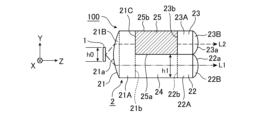
まず、光源分配素子2を含む集光光学系100は、図2から図4に示すように、光源1を含む。
光源1は、車両の前方を照明するための光を出射する。光源1は、光源分配素子2のZ軸の-側に配設され、Z軸の+方向に光を出射する。光源1の光軸は集光光学系100の光軸と一致している。
光源1は、前面に光を出射する矩形、この例では正方形の出射面を有する。
The light
The
The
光源1は、白熱電球、ハロゲンランプ又は蛍光ランプ等の管球光源、発光ダイオード(LED(Light Emitting Diode)以下、LEDと称す。)又はレーザーダイオード(LD(Laser Diode)、以下、LDと称す。)等の半導体光源のいずれかである。
The
二酸化炭素(CO2)の排出と燃料の消費を抑えて環境への負荷を軽減する観点、ハロゲンランプに比べて発光効率が高く、かつ、指向性があり、光学系を小型化、軽量化できる半導体光源を用いるのが好適である。
本開示における集光光学系100では、半導体光源の1つであるLEDを用いる。
From the viewpoint of reducing the burden on the environment by suppressing carbon dioxide ( CO2 ) emissions and fuel consumption, it is preferable to use semiconductor light sources, which have higher luminous efficiency than halogen lamps, are directional, and allow for a smaller and lighter optical system.
The light collecting
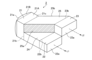
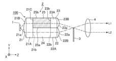
光源分配素子2は、図1から図4に示すように、入射部21と、第1の出射部22と、第2の出射部23と、第1の導光部24と、第2の導光部25とを備える。
入射部21は、光源1からの光が入射される入射面21aを有し、光源1の光軸と直交する平面における一方向である上下方向に沿って位置する第1の接合面21b及び第2の接合面21cを有する。
なお、第1の接合面21b及び第2の接合面21cは、物理的に接合面を有するものではなく、入射部21と第1の出射部22及び第2の出射部23との境界面を示す仮想的な面である。
As shown in FIGS. 1 to 4 , the light-
The
Note that the
入射部21は、直方体形状の基部21Aと、基部21Aと一体形成され、少なくとも一部に正の屈折力を有する凸面形状の入射面21aを表面に持つレンズ21Bを有する。
レンズ21Bは、基部21Aとの接合面が矩形もしくは円形をなした凸レンズである。
入射部21は、レンズ21Bにより、入射面21aから入射された光源1から発せられた光を、発散角を小さくして集光し、基部21Aを介して第1の接合面21b及び第2の接合面21cへ並行光、理想的には平行光を導く。
The
The
The
入射部21の基部21Aは、Y-X面、つまり、水平面(Z-X面)と直交し、光軸に直交する垂直面の形状が正方形である。第1の接合面21bは垂直面の下半分に位置し、第2の接合面21cは垂直面の上半分に位置する。
なお、第1の接合面21bの面積と第2の接合面21cの面積の和が、基部21Aの垂直面の面積となればよい。
また、垂直面の形は正方形に限るものではなく、長方形でもよく、要は矩形であり、下に第1の接合面21b、上に第2の接合面21cが位置し、第1の接合面21bの面積と第2の接合面21cの面積の和が、基部21Aの垂直面の面積となればよい。
The
The sum of the area of the first
Furthermore, the shape of the vertical surface is not limited to a square, but may be a rectangle; in short, it is a rectangle, with the
第1の出射部22は、光を出射する第1の出射面22aと、第1の出射面22aと平行な第3の接合面22bを有する。
第1の出射面22a及び第3の接合面22bは、入射部21の第1の接合面21bと平行であり、同じ形状である。
The
The
第2の出射部23は、光を出射する第2の出射面23aと、第2の出射面23aと平行な第4の接合面23bを有する。
第2の出射面23a及び第4の接合面23bは、入射部21の第2の接合面21cと平行であり、同じ形状である。
The
The
第2の出射面23aは、第1の出射部22の第1の出射面22aと一方向、つまり、上下方向と、光源1の光軸と直交する平面における一方向と直交する他方向、つまり、左右方向に異なる位置に位置する光を出射する。
第1の出射部22の左上辺と第2の出射部23の右下辺が接し、第1の出射面22aの左上の角と第2の出射面23aの右下の角が一致する。
なお、第1の出射面22aの左上の角と第2の出射面23aの右下の角が必ずしも一致する必要はない。
The
The upper left side of the
It is not necessary that the upper left corner of the first
また、第1の出射面22a及び第2の出射面23aは、物理的に出射面を有するものでもよく、また、仮想的な出射面でも良い。
第1の出射面22a及び第2の出射面23aは、物理的に存在するか仮想的な出射面であるかにかかわらず、光源分配素子2からの発光量の基準となる発光基準面である。
また、第3の接合面22b及び第4の接合面23bは、物理的に接合面を有するものではなく、第1の出射部22と第1の導光部24との境界面を示す仮想的な面、及び第2の出射部23と第2の導光部25との境界面を示す仮想的な面である。
Moreover, the
The
In addition, the
第1の導光部24は、入射部21の第1の接合面21bと第1の出射部22の第3の接合面22bとの間に位置し、入射部の第1の接合面21bからの光を第1の出射部22に導く。
第1の導光部24は、第1の接合面21bと第3の接合面22bとを直線的に結ぶ直方体形状をし、Y-X面である垂直断面の形状は第1の接合面21b及び第3の接合面22bと同じ形状である。
The first
The first light-guiding
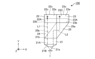
入射部21の入射面21aに入射された光源1からの光の一部である入射部21の第1の接合面21bから第1の導光部24に導かれた光は、図1から図3に2点鎖線矢印にて示すように、第1の光L1として、光源1の光軸に並行に直進し、第1の出射部22の第3の接合面22bに導かれ、第1の出射部22の第1の出射面22aから光源1の光軸に並行な光として出射される。
The light guided from the first
第2の導光部25は、入射部21の第2の接合面21cと第2の出射部23の第4の接合面23bとの間に位置し、他方向、つまり左右方向の対向した側面の右側面に形成された第1の反射面25a及び左右方向の対向した側面の左側面に形成された第2の反射面25bを有し、入射部21の第2の接合面21cからの光を第1の反射面25a及び第2の反射面25bが反射させて第2の出射部23に導く。
The second
第2の導光部25は、第2の接合面21cと第4の接合面23bとを、光源1の光軸に対して左右方向、この例では左方向に45度傾いて直線的に結ぶ方形状をし、Y-X面である垂直断面の形状は第2の接合面21cと第4の接合面23bと同じ形状である。
第2の導光部25の右側面及び左側面は左方向に45度傾き、右側面と左側面は平行である。
The second light-guiding
The right and left side surfaces of the second
第2の導光部25は、他方向、この例では左方向に屈曲する第1の屈曲部と第1の屈曲部と反対方向に屈曲する第2の屈曲部を有し、第1の屈曲部が入射部21の第2の接合面21cの位置であり、第2の屈曲部が第2の出射部23の第4の接合面23bである。
The second light-guiding
入射部21の入射面21aに入射された光源1からの光の他の一部である入射部21の第2の接合面21cから第2の導光部25に導かれた光は、図1から図3に点線矢印にて示すように、第2の光L2として、光源1の光軸に並行に直進し第1の反射面25aに到達した光は、第1の反射面25aにより直角に全反射される。
第1の反射面25aにより全反射され、第2の反射面25bに到達した光は、第2の反射面25bにより直角に全反射され、第2の出射部23の第4の接合面23bに導かれる。
第4の接合面23bに導かれた光は、第2の出射部23の第2の出射面23aから光源1の光軸に並行な光として出射される。
The light guided from the second
The light that is totally reflected by the first reflecting
The light guided to the
光源分配素子2を構成する入射部21と、第1の出射部22と、第2の出射部23と、第1の導光部24と、第2の導光部25は透過性材料により一体形成される。
光源分配素子2は、射出成形により製造され、内部が屈折材で満たされた透過性材料である。
The
The light
光源分配素子2が製造される材料は、光の利用効率の観点から透過性が高く、光源1の直後に配置されることから、耐熱性に優れた材料が好ましい
例えば、硝子又はシリコーン材の透明樹脂が良い。
具体的には、透明樹脂としては、アクリル樹脂(特にPMMA:ポリメチルメタクリレート)、ポリカーボネート(PC)、シクロオレフィン樹脂等が好適である。
The material from which the light
Specifically, suitable transparent resins include acrylic resins (particularly PMMA: polymethyl methacrylate), polycarbonate (PC), cycloolefin resins, and the like.
このように構成された実施の形態1に係る光源分配素子2は、光源1からの光を入射部21の入射面21aにより光の発散角を小さくして入射部21の内部に導き、第1の導光部24及び第2の導光部25の2つの導光部を利用して、入射部21に入射された入射光束を上下方向に2分割して分岐させ、第1の出射部22の第1の出射面22a及び第2の出射部23の第2の出射面23aより、分岐された光束を出射している。
The light
このように、入射部21に入射された入射光束を第1の導光部24及び第2の導光部25により上下方向に2分割して分岐させることにより、発光基準面である第1の出射部22の第1の出射面22a及び第2の出射部23の第2の出射面23aに対する分割方向、つまり、上下方向の光源のみかけ上のサイズを、2分割しない光源の光源サイズより小さくできる。
この時の第1の出射部22の第1の出射面22aと第2の出射部23の第2の出射面23aとのトータルの発光面サイズは光源1からの光に基づく光源サイズと同じである。
In this way, by dividing and branching the incident light beam incident on the
At this time, the total light emitting surface size of the
したがって、光源分配素子2による光利用効率が劣化せずに、上下方向において集光光学系100を薄型化できる。
この点について、さらに説明する。
光源の見かけのサイズとは、光源のある方向の発散角とその方向の光源の辺の長さの積で定められる「アッベの不変量」にて定義される。
Therefore, the light-concentrating
This point will be explained further.
The apparent size of a light source is defined by the "Abbe invariant," which is the product of the divergence angle in a direction of the light source and the length of a side of the light source in that direction.
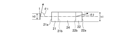
今、図3及び図5に示すように、光源1の高さ、つまり、上下方向の長さをh0、光源1からの光の上下方向の発散角をθ0とし、第1の出射部22の第1の出射面22aの上下方向の長さ、つまり、縦の辺の長さをh1、第1の出射面22aから出射される光の上下方向の発散角をθ1とすると次式(1)の関係になる。
h0×sin θ0>h1×sin θ1 ・・・(1)
Now, as shown in Figures 3 and 5, if the height of the
h0×sin θ0>h1×sin θ1...(1)
一例として、光源1であるLEDの上下方向の長さh0を1mm、LEDからの光の上下方向の発散角θ0を90度とし、第1の出射面22aの上下方向の長さh1を9.0mm、第1の出射面22aから出射される光の上下方向の発散角θ1を3度とすると、式(1)の左辺は次式(2)、式(1)の右辺は次式(3)となる。
h0×sin θ0=1.0 ・・・(2)
h1×sin θ1=0.47 ・・・(3)
As an example, if the vertical length h0 of the LED which is the
h0×sin θ0=1.0...(2)
h1×sin θ1=0.47...(3)
式(2)及び式(3)から明らかなように、集光光学系100は(1)式を満たす。
従って、光源の光束を分割した方向、つまり、上下方向に、発光基準面である第1の出射部22の第1の出射面22a及び第2の出射部23の第2の出射面23aにおける上下方向のみかけ上のサイズを、2分割しない光源の光源サイズより小さくできる。
その結果、光源分配素子2による光利用効率の低下を防いで、上下方向において集光光学系100を薄型化できる。
As is clear from equations (2) and (3), the light-collecting
Therefore, in the direction in which the luminous flux of the light source is divided, i.e., in the vertical direction, the apparent size in the vertical direction of the
As a result, a decrease in the light utilization efficiency due to the light
要するに、実施の形態1に係る光源分配素子2は、第1の出射部22の第1の出射面22aにおける上下方向の長さh0と第1の出射面22aから出射される光の上下方向の発散角θ1との積が、光源1の上下方向の長さh1と光源1からの光の上下方向の発散角θ0との積より小さい値に設定される。
In short, in the light
なお、第2の出射部23の第2の出射面23aにおける上下方向の長さh2と第2の出射面23aから出射される光の上下方向の発散角θ2との積が、第1の出射面22aと光源1との関係と同様に、光源1の上下方向の長さh0と光源1からの光の上下方向の発散角θ0との積より小さい値に設定される。
すなわち、次式(4)を満たすように設定される。
h0×sinθ0>h2×sinθ2 (4)
In addition, the product of the vertical length h2 of the
That is, it is set so as to satisfy the following formula (4).
h0 × sinθ0>h2 × sinθ2 (4)
以上のように、実施の形態1に係る光源分配素子2は、入射部21の第1の接合面21bと第1の出射部22との間に位置し、入射部21の第1の接合面21bからの光を第1の出射部22に導く第1の導光部24と、入射部21の第2の接合面21cと第2の出射部23との間に位置し、他方向の対向した側面の一方の側面に形成された第1の反射面25a及び他方向の対向した側面の他方の側面に形成された第2の反射面25bを有し、入射部21の第2の接合面21cからの光を第1の反射面25a及び第2の反射面25bが反射させて第2の出射部23に導く第2の導光部25と備えているので、構造簡単にして光利用効率を低下させずに小型化できる。
As described above, the light
すなわち、一方向は上下方向、他方向は左右方向とすると、薄型の集光光学系100を作製できる。
なお、実施の形態1における光源分配素子2は、光束の分割数を上下方向に2としたが、これに限られるものではなく、上下方向に3以上であってもよく、また、上下方向及び左右方向に2つずつ計4でもよい。要は、複数の出射部を有し、それぞれが入射部から複数の出射部のそれぞれに光を導く複数の導光部を設ければよい。
That is, if one direction is the up-down direction and the other direction is the left-right direction, a thin focusing
In the light
また、第1の出射面22aを上下方向に2分割し、分割されたそれぞれの面を入射部21の第1の接合面21bと第2の接合面21cとみなし、みなした第1の接合面21bに対して第1の導光部24及び第1の出射部22を形成し、みなした第2の接合面21cに対して第2の導光部25及び第2の出射部23を形成し、第2の出射面23aを上下方向に2分割し、分割されたそれぞれの面を入射部21の第1の接合面21bと第2の接合面21cとみなし、みなした第1の接合面21bに対して第1の導光部24及び第1の出射部22を形成し、みなした第2の接合面21cに対して第2の導光部25及び第2の出射部23を形成したものでもよい。
Also, the
実施の形態2.
実施の形態2に係る光源分配素子2を図6及び図7に基づいて説明する。
実施の形態2に係る光源分配素子2は、実施の形態1に係る光源分配素子2に対して、第1の出射部22及び第2の出射部23それぞれに正の屈折力を有する凸面形状の第1の出射面22a及び第2の出射面23a有する点が相違し、その他の点については同じである。
なお、図6及び図7中、図1から図4に示された符号と同一符号は、同一又は相当部分を示す。
Second Embodiment A light-
The light
In addition, in Figs. 6 and 7, the same reference numerals as those shown in Figs. 1 to 4 indicate the same or corresponding parts.
以下に、実施の形態1に係る光源分配素子2に対する相違点を主に説明する。
第1の出射部22は、第1の導光部24との接合面である第3の接合面22bを有する直方体形状の基部22Aと、第3の接合面22bと対向する面に基部22Aと一体形成され、少なくとも一部に正の屈折力を有する凸面形状の第1の出射面22aを表面に持つレンズ22Bを有する。
第1の出射部22は、レンズ22Bにより、第1の出射面22aから光を集光して出射する。
The following mainly describes the differences from the light-
The
The
第2の出射部23は、第2の導光部25との接合面である第4の接合面23bを有する直方体形状の基部23Aと、第4の接合面23bと対向する面に基部23Aと一体形成され、少なくとも一部に正の屈折力を有する凸面形状の第2の出射面23aを表面に持つレンズ23Bを有する。
第2の出射部23は、レンズ23Bにより、第2の出射面23aから光を集光して出射する。
The
The
このように構成された実施の形態2に係る光源分配素子2にあっても、実施の形態1に係る光源分配素子2と同様の効果を有する他、第1の出射部22のレンズ22Bの表面に形成された凸面形状の第1の出射面22aにより光が集光されて出射され、第2の出射部23のレンズ23Bの第2の出射面23aにより光が集光されて出射されるため、光源分配素子2以降に配される前照灯装置の光学系を、実施の形態1に係る光源分配素子2以降に配される前照灯装置の光学系を更に小型にできる。
The light
実施の形態3.
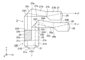
実施の形態3に係る光源分配素子2を図8から図11に基づいて説明する。
実施の形態3に係る光源分配素子2は、実施の形態1に係る光源分配素子2が光源1に対してZ軸上に配されるのに対して、光源1に対してY軸上に配される点で相違し、その結果、第1の出射部22及び第2の出射部23それぞれに、Z軸の+方向に光路を変更するための第1の光路変更部22C及び第2の光路変更部23Cを有する点が相違し、その他の点については同じである。
なお、図8から図11中、図1から図4に示された符号と同一符号は、同一又は相当部分を示す。
Embodiment 3.
A light-
The light
In addition, in Figs. 8 to 11, the same reference numerals as those shown in Figs. 1 to 4 indicate the same or corresponding parts.
以下に、実施の形態3に係る光源分配素子2における実施の形態1に係る光源分配素子2に対する相違点を主に説明する。
光源1は、光源分配素子2のY軸の-側に配設され、Y軸の+方向、つまり、上下方向の上方に光を出射する。光源1の光軸はY軸に沿っており、集光光学系100の光軸と一致している。
実施の形態3に係る光源分配素子2において、一方向は前後方向、つまりZ軸方向、他方向は左右方向、つまり、X方向である。
The following mainly describes the differences between the light-
The
In the light-
光源分配素子2は、光源1のY軸の+側に配設され、レンズ21Bの入射面21aから入射された光源1から発せられた光を、発散角を小さくして集光し、基部21Aを介して第1の接合面21b及び第2の接合面21cへ、Y軸に沿った、つまり、上下方向に並行光、理想的には平行光を導く。
第1の接合面21b及び第2の接合面21cは、一方向である前後方向に沿って位置する。
The light
The first
第1の出射部22は、第1の出射面22aが前後方向の前面に位置し、第1の導光部24に導かれた光を反射して第1の出射面22aに導く第3の反射面22cを有する。
第1の出射部22は、第1の導光部24との接合面である第3の接合面22bを有する直方体形状の基部22Aと、第3の接合面22bと対向する面に基部22Aと一体形成され、前面に第1の出射面22aを持ち、上面に第3の反射面22cが形成された第1の光路変更部22Cを有する。
第3の接合面22bは、入射部21の第1の接合面21bと平行であり、同じ形状である。
The
The
The
第1の光路変更部22Cは、第3の接合面22bと対向する面に対して45度傾斜された斜面を有し、当該斜面に第3の反射面22cが形成され、前面において、当該斜面と第3の接合面22bと対向する面との間が第1の出射面22aとなる。
すなわち、第3の接合面22bと対向する面に導かれた光は、図9から図11に示すように、第3の反射面22cにより全反射されて90度光路が変更され、第1の出射面22aから前後方向の前方に出射される。
The first optical
That is, the light guided to the surface opposite to the
第3の反射面22cを、集光機能を有する反射面としてもよい。この場合、第3の反射面22cは正のパワーを有する反射面となる。
このように、第3の反射面22cに集光機能を持たせることにより、前照灯装置に求められる複雑な配光分布を容易に形成することができる。
また、第3の反射面22cとして複数の集光機能を有する反射面の集合体としてもよい。この場合、第3の反射面22cは、全体として正のパワーを有すればよい。
The third reflecting
In this way, by providing the third reflecting
Moreover, the third reflecting
第2の出射部23は、第2の出射面23aが前後方向の前面に位置し、第2の導光部25に導かれた光を反射して第2の出射面23aに導く第4の反射面23cを有する。
第2の出射部23は、第2の導光部25との接合面である第4の接合面23bを有する直方体形状の基部23Aと、第4の接合面23bと対向する面に基部23Aと一体形成され、前面に第2の出射面23aを持ち、上面に第4の反射面23cが形成された第2の光路変更部23Cを有する。
The
The
第4の接合面23bは、入射部21の第2の接合面21cと平行であり、同じ形状である。
第2の出射面23aは、第1の出射部22の第1の出射面22aと一方向、つまり、前後方向と、光源1の光軸と直交する平面における一方向と直交する他方向、つまり、左右方向に異なる位置に位置する光を出射する。
第1の出射部22の左後辺と第2の出射部23の右前辺が接し、第1の出射面22aの左後の角と第2の出射面23aの右前の角が一致する。
なお、第1の出射面22aの左後の角と第2の出射面23aの右前の角が必ずしも一致する必要はない。
The
The
The left rear side of the
It is not necessary that the rear left corner of the first
第2の光路変更部23Cは、第4の接合面23bと対向する面に対して45度傾斜された斜面を有し、当該斜面に第4の反射面23cが形成され、前面において、当該斜面と第4の接合面23bと対向する面との間が第2の出射面23aとなる。
すなわち、第4の接合面23bと対向する面に導かれた光は、図9から図11に示すように、第4の反射面23cにより全反射されて90度光路が変更され、第2の出射面23aから前後方向の前方に出射される。
The second optical
That is, the light guided to the surface opposite to the
第4の反射面23cを、集光機能を有する反射面としてもよい。この場合、第4の反射面23cは正のパワーを有する反射面となる。
このように、第4の反射面23cに集光機能を持たせることにより、前照灯装置に求められる複雑な配光分布を容易に形成することができる。
また、第4の反射面23cとして複数の集光機能を有する反射面の集合体としてもよい。この場合、第4の反射面23cは、全体として正のパワーを有すればよい。
The fourth reflecting
In this way, by providing the fourth reflecting
Furthermore, the fourth reflecting
第3の反射面22c及び第4の反射面23cが集光機能を有する場合、第3の反射面22cと第4の反射面23cは互いに異なる集光パワーを有することが好ましい。
第3の反射面22cと第4の反射面23cが互いに異なる集光パワーを有することにより、第1の出射部22と第2の出射部23からは互いに異なる配光分布による光が出射される。
このため、前照灯装置に求められる複雑な配光分布を、第1の出射部22と第2の出射部23の合成配光により、より自由度高く、容易に形成することができる。
なお、第3の反射面22c及び第4の反射面23cの少なくとも一方の反射面を、集光機能を有する反射面としてもよい。
When the third reflecting
Since the third reflecting
Therefore, the complex light distribution required for the headlamp device can be easily formed with a higher degree of freedom by the composite light distribution of the
At least one of the third reflecting
第1の出射部22及び第2の出射部23は、光源分配素子2として透過性材料により一体形成されたものであり、第3の接合面22bと対向する面及び第4の接合面23bと対向する面は、物理的に存在する面ではなく、仮想的な面であり、第1の出射面22a及び第2の出射面23aは、物理的に出射面を有するものでもよく、また、仮想的な出射面でも良い。
The
第1の導光部24は、入射部21の第1の接合面21bと第1の出射部22の第3の接合面22bとの間に位置し、入射部の第1の接合面21bからの光を第1の出射部22に導く。
第1の導光部24は、第1の接合面21bと第3の接合面22bとを直線的に結ぶ直方体形状をし、Z-X面である水平断面の形状は第1の接合面21b及び第3の接合面22bと同じ形状である。
The first
The first light-guiding
入射部21の入射面21aに入射された光源1からの光の一部である入射部21の第1の接合面21bから第1の導光部24に導かれた光は、図8から図11に2点鎖線矢印にて示すように、第1の光L1として、光源1の光軸に並行に直進し、第1の出射部22の第3の接合面22bに導かれ、第3の反射面22cにより直角に全反射されて、第1の出射面22aから光源1の光軸に対して直角に屈曲された並行な光として前方に出射される。
The light guided from the first
第2の導光部25は、入射部21の第2の接合面21cと第2の出射部23の第4の接合面23bとの間に位置し、他方向、つまり左右方向の対向した側面の右側面に形成された第1の反射面25a及び左右方向の対向した側面の左側面に形成された第2の反射面25bを有し、入射部21の第2の接合面21cからの光を第1の反射面25a及び第2の反射面25bが反射させて第2の出射部23に導く。
The second
第2の導光部25は、第2の接合面21cと第4の接合面23bとを、光源1の光軸に対して左右方向、この例では左方向に45度傾いて直線的に結ぶ方形状をし、Z-X面である水平断面の形状は第2の接合面21cと第4の接合面23bと同じ形状である。
第2の導光部25の右側面及び左側面は左方向に45度傾き、右側面と左側面は平行である。
The second light-guiding
The right and left side surfaces of the second
第2の導光部25は、他方向、この例では左方向に屈曲する第1の屈曲部と第1の屈曲部と反対方向に屈曲する第2の屈曲部を有し、第1の屈曲部が入射部21の第2の接合面21cの位置であり、第2の屈曲部が第2の出射部23の第4の接合面23bである。
The second light-guiding
入射部21の入射面21aに入射された光源1からの光の他の一部である入射部21の第2の接合面21cから第2の導光部25に導かれた光は、図8から図11に点線矢印にて示すように、第2の光L2として、光源1の光軸に並行に直進し第1の反射面25aに到達した光は、第1の反射面25aにより直角に全反射される。
The light guided from the second
第1の反射面25aにより全反射され、第2の反射面25bに到達した光は、第2の反射面25bにより直角に全反射され、第2の出射部23の第4の接合面23bに導かれる。
第4の接合面23bに導かれた光は、第4の反射面23cにより全反射されて、第2の出射面23aから光源1の光軸に対して直角に屈曲された並行な光として前方に出射される。
The light that is totally reflected by the first reflecting
The light guided to the
このように構成された実施の形態3に係る光源分配素子2は、光源1からの光を入射部21の入射面21aにより光の発散角を小さくして入射部21の内部に導き、第1の導光部24及び第2の導光部25の2つの導光部を利用して、入射部21に入射された入射光束を前後方向に2分割して分岐させ、分岐された入射光束を第1の出射部22の第3の反射面22c及び第2の出射部23の第4の反射面23cにより全反射して光源1の光軸に対して直角に屈曲された並行な光束として第1の出射面22a及び第2の出射面23aから前方に分岐された光束を出射している。
The light
実施の形態3に係る光源分配素子2は、実施の形態1に係る光源分配素子2と同様に、第1の出射部22の第1の出射面22aにおける上下方向の長さh1と第1の出射面22aから出射される光の上下方向の発散角θ1との積が、光源1の前後方向の長さh0と光源1からの光の前後方向の発散角θ0との積より小さい値に設定される。
すなわち、式(1)を満たすように設定される。
The light
That is, it is set so as to satisfy the formula (1).
また、第2の出射部23の第2の出射面23aにおける上下方向の長さh2と第2の出射面23aから出射される光の上下方向の発散角θ2との積が、光源1の前後方向の長さh0と光源1からの光の前後方向の発散角θ0との積より小さい値に設定される。
すなわち、次式(4)を満たすように設定される。
In addition, the product of the vertical length h2 of the
That is, it is set so as to satisfy the following formula (4).
このように構成された実施の形態3に係る光源分配素子2は、実施の形態1に係る光源分配素子2と同様に、構造簡単にして光利用効率を低下させずに小型化できる。
さらに、分岐された入射光束を第1の出射部22の第3の反射面22c及び第2の出射部23の第4の反射面23cにより全反射して光源1の光軸に対して直角に屈曲された並行な光束として第1の出射面22a及び第2の出射面23aから前方に分岐された光束を出射しているので、光源分配素子2からの光を取り出す位置を容易に調整できる。
The light-
Furthermore, the branched incident light beam is totally reflected by the third reflecting
すなわち、実施の形態3に係る光源分配素子2は、第1の出射部22の第1の出射面22aから出射される光と第2の出射部23の第2の出射面23aから出射される光との上下方向の高さを同じとしているが、第1の出射部22の基部22Aの上下方向の長さと第2の出射部23の基部23Aの上下方向の長さを変えることにより、第1の出射面22aから出射される光と第2の出射面23aから出射される光との上下方向の高さを変えることができ、前照灯装置における自由なデザインに対応でき、結果として前照灯装置の意匠性を向上できる。
In other words, in the light
また、第1の出射部22の第3の反射面22c及び第2の出射部23の第4の反射面23cを、集光機能を有する反射面とすることにより、前照灯装置に求められる複雑な配光分布を容易に形成することができる。
さらに、第3の反射面22cと第4の反射面23cが互いに異なる集光パワーを有する反射面とすることにより、前照灯装置に求められる複雑な配光分布を、第1の出射部22と第2の出射部23の合成配光により、より自由度高く、容易に形成することができる。
Furthermore, by making the third reflecting
Furthermore, by making the third reflecting
なお、実施の形態3に係る光源分配素子2は、実施の形態2に係る光源分配素子2に示したように、第1の出射部22として第1の光路変更部22Cにおける第1の出射面22aを、少なくとも一部に正の屈折力を有する凸面形状の第1の出射面22aを表面に持つレンズ22Bとし、第2の出射部23として第2の光路変更部23Cにおける第2の出射面23aを、少なくとも一部に正の屈折力を有する凸面形状の第2の出射面23aを表面に持つレンズ23Bとしたものでもよい。
As shown in the light
実施の形態4.
実施の形態4に係る前照灯装置を図12に基づいて説明する。
なお、図12中、図6及び図7に示された符号と同一符号は、同一又は相当部分を示す。
実施の形態4に係る前照灯装置は、自動二輪車用前照灯装置におけるロービームである。
なお、自動車用前照灯装置のロービームに適用する場合は、実施の形態4として示した前照灯装置を、自動車用前照灯装置の一要素として左右方向に複数並列に配置すればよい。この場合、シェード3と投影レンズ4それぞれは複数の要素に対して一体的に形成されるものでよい。
Embodiment 4.
A headlamp device according to a fourth embodiment will be described with reference to FIG.
In FIG. 12, the same reference numerals as those shown in FIGS. 6 and 7 indicate the same or corresponding parts.
The headlamp device according to the fourth embodiment is a low beam headlamp device for a motorcycle.
When the headlamp device is applied to a low beam of an automobile headlamp device, a plurality of the headlamp devices shown in the fourth embodiment may be arranged in parallel in the left-right direction as one element of the automobile headlamp device. In this case, the shade 3 and the projection lens 4 may each be formed integrally with the plurality of elements.
実施の形態4に係る前照灯装置は、光源1と、光源分配素子2と、シェード3と、投影レンズ4とを備える。
光源1と光源分配素子2を有する集光光学系100は、実施の形態2に係る光源分配素子2を含む集光光学系100である。
但し、第1の出射部22にレンズ22Bを有し、第2の出射部23にレンズ23Bを有する実施の形態3に係る光源分配素子2を含む集光光学系100でもよい。
The headlamp device according to the fourth embodiment includes a
The light-collecting
However, the light-collecting
シェード3は、光源分配素子2の集光位置に配置され、光源分配素子2から出射される光に対してカットオフラインを形成する。
すなわち、シェード3は、カットオフラインの上側、つまり、配光パターンの外側が暗く、カットオフラインの下側、つまり、配光パターンの内側が明るくなるように、光源分配素子2から出射される光に対して、光の一部を遮蔽する。
The shade 3 is disposed at a light collecting position of the light-
That is, the shade 3 blocks a portion of the light emitted from the light-
投影レンズ4は、シェード3により光の一部が遮蔽された光が入射され、透過したカットオフラインが形成された配光パターンの光を、前方へロービーム照射光として出射する。
投影レンズ4は、シェード3に対する光源分配素子2の位置関係と逆の関係に位置し、つまり、投影レンズ4の焦点位置にシェード3が配置される。
The projection lens 4 receives the light, part of which has been blocked by the shade 3, and emits the transmitted light having a light distribution pattern in which a cutoff line is formed forward as low beam irradiation light.
The projection lens 4 is located in a position opposite to the positional relationship of the light
このように構成された実施の形態4に係る前照灯装置は、光源1からの光が入射面21aに入射された光源分配素子2が、入射面21aにより光の発散角を小さくし、第1の導光部24及び第2の導光部25の2つの導光部を利用して、2分割に分岐された並行な入射光束それぞれを第1の出射部22の第1の出射面22a及び第2の出射部23の第2の出射面23aにより集光してシェード3へ出射する。
In the headlamp device according to the fourth embodiment configured in this manner, the light
シェード3が、第1の出射面22a及び第2の出射面23aそれぞれにより集光された光を一部遮蔽し、投影レンズ4がシェード3により一部遮蔽された光を前方へカットオフラインが形成された配光パターンのロービーム照射光として出射する。
The shade 3 partially blocks the light collected by the
従って、実施の形態4に係る前照灯装置は、構造簡単にして光利用効率を低下させずに小型化できる実施の形態2に係る光源分配素子2を含む集光光学系100を用いているため、投影レンズ4の上下方向も短くでき、薄型な光学系を有することにより、デザイン性及び意匠性に対して柔軟に対応できる。
The headlamp device according to the fourth embodiment therefore uses the light-collecting
実施の形態5.
実施の形態5に係る前照灯モジュールを図13に基づいて説明する。
なお、図13中、図8から図11に示された符号と同一符号は、同一又は相当部分を示す。
実施の形態5に係る前照灯モジュールは、自動二輪車用前照灯装置におけるロービームに適用される。
なお、自動車用前照灯装置のロービームに適用する場合は、実施の形態5として示した前照灯モジュールを、自動車用前照灯装置の一要素として左右方向に複数並列に配置すればよい。
Embodiment 5.
A headlamp module according to a fifth embodiment will be described with reference to FIG.
In FIG. 13, the same reference numerals as those shown in FIGS. 8 to 11 indicate the same or corresponding parts.
The headlamp module according to the fifth embodiment is applied to a low beam in a headlamp device for a motorcycle.
When applied to a low beam automobile headlamp device, a plurality of headlamp modules shown in the fifth embodiment may be arranged in parallel in the left-right direction as one element of the automobile headlamp device.
実施の形態5に係る前照灯モジュールは、実施の形態3に係る光源分配素子2に、第1のカットオフライン形成部26及び第2のカットオフライン形成部27並びに第1の投影レンズ28及び第2の投影レンズ29を一体的に形成したものである。
The headlamp module according to the fifth embodiment is the light
第1のカットオフライン形成部26は、光源分配素子2の第1の出射部22の第1の出射面22aから前後方向の前方に延在して一体的に形成され、第1の出射面22aから出射される光を反射してカットオフラインが形成された光を出射する第5の反射面26aを上下方向の下面に有する。
The first cutoff
第1のカットオフライン形成部26は、第1の領域部26Aと第2の領域部26Bを有する。
第1の領域部26Aは一端面が第1の出射部22の第1の出射面22aとの接合面であり、下面がZ-X面、つまり水平面に位置し、上面が水平面に対して下向きに傾斜を持つ面であり、右側面及び左側面それぞれは第1の導光部24の右側面及び左側面それぞれと同一平面上に位置する。
The first cutoff
One end face of the
第1の出射部22の第3の反射面22cは、第3の接合面22bから導かれた光を全反射して第1の出射面22aから第1のカットオフライン形成部26の第5の反射面26aに集光して導く。第3の反射面22cは、水平面である第3の接合面22bに対して45度未満の傾きをもって形成される。
なお、第3の反射面22cは、実施の形態3に係る光源分配素子2と同様に集光機能を有する反射面としてもよい。
The third reflecting
The third reflecting
第2の領域部26Bは、一端面が第1の領域部26Aの他端面との接合面であり、第1の領域部26Aから前方に一体的に延在し、上面及び下面が水平面に位置し、右側面及び左側面それぞれは第1の領域部26Aの右側面及び左側面それぞれと同一平面上に位置する。
第2の領域部26Bは、第1の出射面22aから出射された光を第5の反射面26aにより反射されたカットオフラインを有する光を他端面に導く。
The
The
第1の領域部26Aと第2の領域部26Bの接合面における下線、つまり、第5の反射面26aの前端がカットオフラインを形成するための稜線26bである。
稜線26bは、カットオフラインの上側、つまり、配光パターンの外側が暗く、カットオフラインの下側、つまり、配光パターンの内側が明るくなるように位置し、第5の反射面26aが入射された光を反射する。
An underline on the joint surface between the
The
第2のカットオフライン形成部27は、第1の領域部27Aと第2の領域部27Bを有する。
第1の領域部27Aは一端面が第2の出射部23の第2の出射面23aとの接合面であり、下面がZ-X面、つまり水平面に位置し、上面が水平面に対して下向きに傾斜を持つ面であり、右側面及び左側面それぞれは第2の導光部25の右側面及び左側面それぞれと同一平面上に位置する。
The second cutoff
One end face of the
第2の出射部23の第4の反射面23cは、第4の接合面23bから導かれた光を全反射して第2の出射面23aから第6の反射面27aに集光して導く。第4の反射面23cは、水平面である第4の接合面23bに対して45度未満の傾きをもって形成される。
なお、第4の反射面23cは、実施の形態3に係る光源分配素子2と同様に集光機能を有する反射面としてもよい。
The fourth reflecting
The fourth reflecting
第2の出射部23の基部23Aの上下方向の長さを第1の出射部22の基部22Aの上下方向の長さより長くし、第2の出射部23の第2の出射面23aの高さを第1の出射部22の第1の出射面22aの高さより高くしている。
The vertical length of the
第2の領域部27Bは、一端面が第1の領域部27Aの他端面との接合面であり、第1の領域部27Aから前方に一体的に延在し、上面及び下面が水平面に位置し、右側面及び左側面それぞれは第1の領域部27Aの右側面及び左側面それぞれと同一平面上に位置する。
第2の領域部27Bは、第2の出射面23aから出射された光を第6の反射面27aにより反射されたカットオフラインを有する光を他端面に導く。
The
The
第1の領域部27Aと第2の領域部27Bの接合面における下線、つまり、第6の反射面27aの前端がカットオフラインを形成するための稜線27bである。
稜線27bは、カットオフラインの上側、つまり、配光パターンの外側が暗く、カットオフラインの下側、つまり、配光パターンの内側が明るくなるように位置し、第6の反射面27aが入射された光を反射する。
An underline on the joint surface between the
The
第1の投影レンズ28は、矩形もしくは円形の平坦面が第2の領域部26Bの他端面との接合面であり、表面に凸面形状の出射面を持つ凸レンズである。
第1の投影レンズ28は、第5の反射面26aに反射された光束を、カットオフラインを有する配光パターンの光であるロービーム照射光として前方へ出射する。
第1の投影レンズ28の焦点位置は、稜線26bに位置する。
The
The
The focal position of the
第2の投影レンズ29は、矩形もしくは円形の平坦面が第2の領域部27Bの他端面との接合面であり、表面に凸面形状の出射面を持つ凸レンズである。
第2の投影レンズ29は、第6の反射面27aに反射された光束を、カットオフラインを有する配光パターンの光であるロービーム照射光として前方へ出射する。
第2の投影レンズ29の焦点位置は、稜線27bに位置する。
The
The
The focal position of the
第1のカットオフライン形成部26及び第2のカットオフライン形成部27並びに第1の投影レンズ28及び第2の投影レンズ29は、光源分配素子2と透過性材料により一体形成される。
The first cutoff
第1の出射部22の第1の出射面22aと、第1のカットオフライン形成部26における第1の領域部26Aの一端面及び他端面と第2の領域部26Bの一端面及び他端面と、第1の投影レンズ28の平坦面と、第2の出射部23の第2の出射面23aと、第2のカットオフライン形成部27における第1の領域部27Aの一端面及び他端面と第2の領域部27Bの一端面及び他端面と、第2の投影レンズ29の平坦面は、物理的に存在する面ではなく、仮想的な面である。
The
このように構成された実施の形態5に係る前照灯モジュールは、光源1からの光が入射面21aに入射された光源分配素子2が、入射面21aにより光の発散角を小さくし、第1の導光部24及び第2の導光部25の2つの導光部を利用して、2分割に分岐された並行な入射光束それぞれを第1の出射部22及び第2の出射部23から第1のカットオフライン形成部26及び第2のカットオフライン形成部27に導く。
In the headlamp module according to the fifth embodiment, which is configured in this manner, the light
第1のカットオフライン形成部26及び第1の投影レンズ28並びに第2のカットオフライン形成部27及び第2の投影レンズ29それぞれが、第1の出射部22の第1の出射面22a及び第2の出射部23の第2の出射面23aそれぞれから出射された光を、カットオフラインを有する配光パターンの光であるロービーム照射光として前方へ出射する。
The first cutoff
従って、実施の形態5に係る前照灯モジュールは、構造簡単にして光利用効率を低下させずに小型化できる実施の形態3に係る光源分配素子2を用い、かつ、第1のカットオフライン形成部26及び第1の投影レンズ28並びに第2のカットオフライン形成部27及び第2の投影レンズ29を光源分配素子2と一体的に構成したので、配置精度のばらつきに強く、取り扱いが容易な構造簡単にして光利用効率を低下させずに小型化できるロービーム照射光の光学系を形成できる。
The headlamp module according to embodiment 5 therefore uses the light
しかも、第1の領域部26Aと第2の領域部26Bの接合面における下線、つまり、第5の反射面26aの前端を、カットオフラインを形成するための稜線26bとし、第1の領域部27Aと第2の領域部27Bの接合面における下線、つまり、第6の反射面27aの前端を、カットオフラインを形成するための稜線27bとしているため、稜線26b及び稜線27bの形状によって、任意であり、所望のカットオフ形状を有する配光パターンを、実施の形態5に係る前照灯モジュールから投影できる。
Moreover, the underline at the joining surface between the
なお、実施の形態5に係る前照灯モジュールは、第1の投影レンズ28及び第2の投影レンズ29を有するものとしたが、第1の投影レンズ28及び第2の投影レンズ29を前照灯モジュールに一体的に形成しなくともよい。
Note that the headlight module according to embodiment 5 has a
すなわち、第1のカットオフライン形成部26における第2の領域部26Bの他端面である平坦面、及び第2のカットオフライン形成部27における第2の領域部26Bの他端面である平坦面から光を出射する構成でもよい。
また、第1の投影レンズ28及び第2の投影レンズ29として表面に凹面形状の出射面を持つ凹レンズであってもよい。
このように出射面を平坦面又は凹面とすることにより、光が拡散する配光を前方に照射できる。
In other words, the configuration may be such that light is emitted from a flat surface that is the other end surface of the
Moreover, the
By making the emission surface flat or concave in this manner, it is possible to irradiate the light forward with a diffused light distribution.
なお、実施の形態1から実施の形態5の説明において、「平行」及び「垂直」などの部品間の位置関係又及び部品の形状を示す用語は、製造上の公差や組立て上のばらつきなどを考慮した範囲を含む。 In the explanations of the first to fifth embodiments, terms such as "parallel" and "perpendicular" that indicate the positional relationship between parts or the shape of parts include a range that takes into account manufacturing tolerances and assembly variations.
また、各実施の形態の自由な組み合わせ、あるいは各実施の形態の任意の構成要素の変形、もしくは各実施の形態において任意の構成要素の省略が可能である。 Furthermore, any combination of the embodiments is possible, or any component of each embodiment may be modified, or any component of each embodiment may be omitted.
本開示に係る前照灯装置用光源分配素子、前照灯装置、及び前照灯モジュールは、自動二輪車用及び自動車用のヘッドライト、特に、ロービームに用いるのが好適である。 The light source distribution element for a headlamp device, the headlamp device, and the headlamp module disclosed herein are suitable for use in motorcycle and automobile headlights, particularly in low beam headlights.
100 集光光学系、1 光源、2 光源分配素子、21 入射部、21A 基部、21B レンズ、21a 入射面、21b 第1の接合面、21c 第2の接合面、21A 基部、21B レンズ、22 第1の出射部、22a 第1の出射面、22b 第3の接合面、22c 第3の反射面、22A 基部、22B レンズ、22C 第1の光路変更部、23 第2の出射部、23a 第2の出射面、23b 第4の接合面、23c 第4の反射面、23A 基部、23B レンズ、23C 第2の光路変更部、24 第1の導光部、25 第2の導光部、25a 第1の反射面、25b 第2の反射面、26 第1のカットオフライン形成部、26a 第5の反射面、27 第2のカットオフライン形成部、27a 第6の反射面、28 第1の投影レンズ、29 第2の投影レンズ、3 シェード、4 投影レンズ。 100 Light collecting optical system, 1 Light source, 2 Light source distribution element, 21 Incident portion, 21A Base portion, 21B Lens, 21a Incident surface, 21b First bonding surface, 21c Second bonding surface, 21A Base portion, 21B Lens, 22 First exit portion, 22a First exit surface, 22b Third bonding surface, 22c Third reflecting surface, 22A Base portion, 22B Lens, 22C First optical path changing portion , 23 Second exit portion, 23a Second exit surface, 23b Fourth bonding surface, 23c Fourth reflecting surface, 23A Base portion, 23B Lens, 23C Second optical path changing portion, 24 First light guiding portion, 25 Second light guiding portion, 25a First reflecting surface, 25b Second reflecting surface, 26 First cutoff line forming portion, 26a Fifth reflecting surface, 27 second cutoff line forming portion, 27a sixth reflecting surface, 28 first projection lens, 29 second projection lens, 3 shade, 4 projection lens.
Claims (12)
光を出射する第1の出射面を有する第1の出射部と、
前記第1の出射部の第1の出射面と前記一方向及び前記光源の光軸と直交する平面における前記一方向と直交する他方向に異なる位置に位置する光を出射する第2の出射面を有する第2の出射部と、
前記入射部の第1の接合面と前記第1の出射部との間に位置し、前記入射部の第1の接合面からの光を前記第1の出射部に導く第1の導光部と、
前記入射部の第2の接合面と前記第2の出射部との間に位置し、前記他方向の対向した側面の一方の側面に形成された第1の反射面及び前記他方向の対向した側面の他方の側面に形成された第2の反射面を有し、前記入射部の第2の接合面からの光を前記第1の反射面及び第2の反射面が反射させて前記第2の出射部に導く第2の導光部と、
を備え、
前記光源の一方向の長さをh0、前記入射部の入射面における一方向の光の発散角をθ0、前記第1の出射部の第1の出射面における一方向の長さをh1、前記第1の出射部の第1の出射面における一方向の光の発散角をθ1、前記第2の出射部の第2の出射面における一方向の長さをh2、前記第2の出射部の第2の出射面における一方向の光の発散角をθ2とすると、h0×sinθ0>h1×sinθ1及びh0×sinθ0>h2×sinθ2の関係が成り立ち、
前記第1の出射部の第1の出射面及び前記第2の出射部の第2の出射面それぞれが、表面の少なくとも一部に屈折力を有する凸面形状のレンズを持つ、
前照灯装置用光源分配素子。 an incidence section having an incidence surface to which light from a light source is incident, the incidence section having a first bonding surface and a second bonding surface positioned along one direction in a plane perpendicular to an optical axis of the light source;
a first emission section having a first emission surface that emits light;
a second emission section having a second emission surface that emits light located at a different position in another direction perpendicular to the one direction on a plane perpendicular to the first emission surface of the first emission section and the one direction and an optical axis of the light source;
a first light guiding portion located between a first bonding surface of the incident portion and the first exit portion, the first light guiding portion guiding light from the first bonding surface of the incident portion to the first exit portion;
a second light guiding section that is located between the second bonding surface of the incident section and the second exit section, the second light guiding section having a first reflecting surface formed on one of the side surfaces facing in the other direction and a second reflecting surface formed on the other of the side surfaces facing in the other direction, and that guides light from the second bonding surface of the incident section to the second exit section by being reflected by the first reflecting surface and the second reflecting surface;
Equipped with
When the length in one direction of the light source is h0, the divergence angle of the light in one direction at the incident surface of the incident portion is θ0, the length in one direction at the first exit surface of the first exit portion is h1, the divergence angle of the light in one direction at the first exit surface of the first exit portion is θ1, the length in one direction at the second exit surface of the second exit portion is h2, and the divergence angle of the light in one direction at the second exit surface of the second exit portion is θ2, the relationships of h0×sinθ0>h1×sinθ1 and h0×sinθ0>h2×sinθ2 are satisfied,
Each of the first exit surface of the first exit portion and the second exit surface of the second exit portion has a convex lens having refractive power on at least a part of the surface.
A light source distribution element for a headlamp device.
光を出射する第1の出射面を有する第1の出射部と、
前記第1の出射部の第1の出射面と前記一方向及び前記光源の光軸と直交する平面における前記一方向と直交する他方向に異なる位置に位置する光を出射する第2の出射面を有する第2の出射部と、
前記入射部の第1の接合面と前記第1の出射部との間に位置し、前記入射部の第1の接合面からの光を前記第1の出射部に導く第1の導光部と、
前記入射部の第2の接合面と前記第2の出射部との間に位置し、前記他方向の対向した側面の一方の側面に形成された第1の反射面及び前記他方向の対向した側面の他方の側面に形成された第2の反射面を有し、前記入射部の第2の接合面からの光を前記第1の反射面及び第2の反射面が反射させて前記第2の出射部に導く第2の導光部と、
を備え、
前記一方向は前後方向であり、前記他方向は左右方向であり、
前記第1の出射部の第1の出射面は前記前後方向の前面に位置し、前記第1の出射部は、前記第1の導光部に導かれた光を反射して前記第1の出射面に導く第3の反射面を有し、
前記第2の出射部の第2の出射面は前記前後方向の前面に位置し、前記第2の出射部は、前記第2の導光部に導かれた光を反射して前記第2の出射面に導く第4の反射面を有し、
前記第3の反射面は複数の集光機能を有する反射面の集合体である、
前照灯装置用光源分配素子。 an incidence section having an incidence surface to which light from a light source is incident, the incidence section having a first bonding surface and a second bonding surface positioned along one direction in a plane perpendicular to an optical axis of the light source;
a first emission section having a first emission surface that emits light;
a second emission section having a second emission surface that emits light located at a different position in another direction perpendicular to the one direction on a plane perpendicular to the first emission surface of the first emission section and the one direction and an optical axis of the light source;
a first light guiding portion located between a first bonding surface of the incident portion and the first exit portion, the first light guiding portion guiding light from the first bonding surface of the incident portion to the first exit portion;
a second light guiding section that is located between the second bonding surface of the incident section and the second exit section, the second light guiding section having a first reflecting surface formed on one of the side surfaces facing in the other direction and a second reflecting surface formed on the other of the side surfaces facing in the other direction, and that guides light from the second bonding surface of the incident section to the second exit section by being reflected by the first reflecting surface and the second reflecting surface;
Equipped with
The one direction is a front-rear direction, and the other direction is a left-right direction,
a first exit surface of the first exit portion is located on a front surface in the front-rear direction, and the first exit portion has a third reflecting surface that reflects the light guided to the first light guiding portion and guides the light to the first exit surface,
a second exit surface of the second exit portion is located on a front surface in the front-rear direction, and the second exit portion has a fourth reflecting surface that reflects the light guided to the second light guiding portion and guides the light to the second exit surface,
The third reflecting surface is a collection of a plurality of reflecting surfaces having a light collecting function.
A light source distribution element for a headlamp device.
光を出射する第1の出射面を有する第1の出射部と、
前記第1の出射部の第1の出射面と前記一方向及び前記光源の光軸と直交する平面における前記一方向と直交する他方向に異なる位置に位置する光を出射する第2の出射面を有する第2の出射部と、
前記入射部の第1の接合面と前記第1の出射部との間に位置し、前記入射部の第1の接合面からの光を前記第1の出射部に導く第1の導光部と、
前記入射部の第2の接合面と前記第2の出射部との間に位置し、前記他方向の対向した側面の一方の側面に形成された第1の反射面及び前記他方向の対向した側面の他方の側面に形成された第2の反射面を有し、前記入射部の第2の接合面からの光を前記第1の反射面及び第2の反射面が反射させて前記第2の出射部に導く第2の導光部と、
を備え、
前記一方向は前後方向であり、前記他方向は左右方向であり、
前記第1の出射部の第1の出射面は前記前後方向の前面に位置し、前記第1の出射部は、前記第1の導光部に導かれた光を反射して前記第1の出射面に導く第3の反射面を有し、
前記第2の出射部の第2の出射面は前記前後方向の前面に位置し、前記第2の出射部は、前記第2の導光部に導かれた光を反射して前記第2の出射面に導く第4の反射面を有し、
前記第4の反射面は複数の集光機能を有する反射面の集合体である、
前照灯装置用光源分配素子。 an incidence section having an incidence surface to which light from a light source is incident, the incidence section having a first bonding surface and a second bonding surface positioned along one direction in a plane perpendicular to an optical axis of the light source;
a first emission section having a first emission surface that emits light;
a second emission section having a second emission surface that emits light located at a different position in another direction perpendicular to the one direction on a plane perpendicular to the first emission surface of the first emission section and the one direction and an optical axis of the light source;
a first light guiding portion located between a first bonding surface of the incident portion and the first exit portion, the first light guiding portion guiding light from the first bonding surface of the incident portion to the first exit portion;
a second light guiding section that is located between the second bonding surface of the incident section and the second exit section, the second light guiding section having a first reflecting surface formed on one of the side surfaces facing in the other direction and a second reflecting surface formed on the other of the side surfaces facing in the other direction, and that guides light from the second bonding surface of the incident section to the second exit section by being reflected by the first reflecting surface and the second reflecting surface;
Equipped with
The one direction is a front-rear direction, and the other direction is a left-right direction,
a first exit surface of the first exit portion is located on a front surface in the front-rear direction, and the first exit portion has a third reflecting surface that reflects the light guided to the first light guiding portion and guides the light to the first exit surface,
a second exit surface of the second exit portion is located on a front surface in the front-rear direction, and the second exit portion has a fourth reflecting surface that reflects the light guided to the second light guiding portion and guides the light to the second exit surface,
The fourth reflecting surface is a collection of a plurality of reflecting surfaces having a light collecting function.
A light source distribution element for a headlamp device.
前記第2の導光部は、前記入射部の第1の接合面と前記第1の出射部との間に、前記他方向に屈曲する第1の屈曲部と前記第1の屈曲部と反対方向に屈曲する第2の屈曲部を有する、
請求項1から請求項5のいずれか1項に記載の前照灯装置用光源分配素子。 the first light guiding portion is formed linearly between a first joint surface of the incident portion and the first emission portion,
the second light guiding section has, between a first joint surface of the incident section and the first emission section, a first bent section bent in the other direction and a second bent section bent in a direction opposite to the first bent section;
The light source distribution element for a headlamp device according to any one of claims 1 to 5.
前記前照灯装置用光源分配素子の集光位置に配置され、前記前照灯装置用光源分配素子から出射される光に対してカットオフラインを形成するシェードと、
前記シェードによりカットオフラインが形成された光を投影する投影レンズと、
備えた前照灯装置。 A light source distribution element for a headlamp device according to any one of claims 1 to 8,
a shade that is disposed at a light collecting position of the light source distribution element for the headlamp device and forms a cutoff line for light emitted from the light source distribution element for the headlamp device;
a projection lens that projects light having a cutoff line formed by the shade;
Equipped with headlight device.
前記前照灯装置用光源分配素子の第1の出射面から一体的に形成され、前記第1の出射面から出射される光に対してカットオフラインが形成された光を出射する第1のカットオフライン形成部と、
前記前照灯装置用光源分配素子の第2の出射面から一体的に形成され、前記第2の出射面から出射される光に対してカットオフラインが形成された光を出射する第2のカットオフライン形成部と、
備えた前照灯モジュール。 A light source distribution element for a headlamp device according to any one of claims 1 to 8,
a first cutoff line forming portion that is integrally formed with a first emission surface of the headlamp device light source distribution element and that emits light having a cutoff line formed therein with respect to light emitted from the first emission surface;
a second cutoff line forming portion that is integrally formed with a second emission surface of the headlamp device light source distribution element and that emits light having a cutoff line formed therein with respect to light emitted from the second emission surface;
Equipped with a headlamp module.
前記前照灯装置用光源分配素子の第1の出射面から前記前後方向に延在して一体的に形成され、前記光源の光軸に沿った上下方向の下面に、前記第1の出射面から出射される光を反射してカットオフラインが形成された光を出射する第5の反射面を有する第1のカットオフライン形成部と、
前記前照灯装置用光源分配素子の第2の出射面から前記前後方向に延在して一体的に形成され、前記上下方向の下面に、前記第2の出射面から出射される光を反射してカットオフラインが形成された光を出射する第6の反射面を有する第2のカットオフライン形成部と、
備えた前照灯モジュール。 A light source distribution element for a headlamp device according to any one of claims 2 to 4,
a first cutoff line forming portion that is integrally formed so as to extend in the front-rear direction from a first emission surface of the headlamp device light source distribution element, and has a fifth reflecting surface on a lower surface in a vertical direction along an optical axis of the light source, the fifth reflecting surface reflecting the light emitted from the first emission surface and emitting light on which a cutoff line is formed;
a second cutoff line forming portion that is integrally formed so as to extend in the front-rear direction from the second emission surface of the headlamp device light source distribution element, and has a sixth reflecting surface on a lower surface in the up-down direction, the sixth reflecting surface reflecting the light emitted from the second emission surface and emitting light on which a cutoff line is formed;
Equipped with a headlamp module.
前記第2のカットオフライン形成部は、先端に一体的に形成された第2の投影レンズを有する、
請求項11に記載の前照灯モジュール。 the first cutoff line forming unit has a first projection lens integrally formed at a tip thereof,
the second cutoff line forming unit has a second projection lens integrally formed at a tip thereof;
12. A headlamp module according to claim 11.
Priority Applications (1)
| Application Number | Priority Date | Filing Date | Title |
|---|---|---|---|
| JP2022025177A JP7675673B2 (en) | 2021-05-12 | 2022-02-22 | Light source distribution element for headlamp device, headlamp device, and headlamp module |
Applications Claiming Priority (3)
| Application Number | Priority Date | Filing Date | Title |
|---|---|---|---|
| JP2021571325A JP7031087B1 (en) | 2021-05-12 | 2021-05-12 | Light source distribution element for headlight device, headlight device, and headlight module |
| PCT/JP2021/018017 WO2022239140A1 (en) | 2021-05-12 | 2021-05-12 | Light source distribution element for headlight device, headlight device, and headlight module |
| JP2022025177A JP7675673B2 (en) | 2021-05-12 | 2022-02-22 | Light source distribution element for headlamp device, headlamp device, and headlamp module |
Related Parent Applications (1)
| Application Number | Title | Priority Date | Filing Date |
|---|---|---|---|
| JP2021571325A Division JP7031087B1 (en) | 2021-05-12 | 2021-05-12 | Light source distribution element for headlight device, headlight device, and headlight module |
Publications (3)
| Publication Number | Publication Date |
|---|---|
| JP2022176069A JP2022176069A (en) | 2022-11-25 |
| JP2022176069A5 JP2022176069A5 (en) | 2024-04-23 |
| JP7675673B2 true JP7675673B2 (en) | 2025-05-13 |
Family
ID=81215062
Family Applications (2)
| Application Number | Title | Priority Date | Filing Date |
|---|---|---|---|
| JP2021571325A Active JP7031087B1 (en) | 2021-05-12 | 2021-05-12 | Light source distribution element for headlight device, headlight device, and headlight module |
| JP2022025177A Active JP7675673B2 (en) | 2021-05-12 | 2022-02-22 | Light source distribution element for headlamp device, headlamp device, and headlamp module |
Family Applications Before (1)
| Application Number | Title | Priority Date | Filing Date |
|---|---|---|---|
| JP2021571325A Active JP7031087B1 (en) | 2021-05-12 | 2021-05-12 | Light source distribution element for headlight device, headlight device, and headlight module |
Country Status (5)
| Country | Link |
|---|---|
| US (1) | US12209725B2 (en) |
| JP (2) | JP7031087B1 (en) |
| CN (1) | CN117321334A (en) |
| DE (1) | DE112021007647T5 (en) |
| WO (1) | WO2022239140A1 (en) |
Families Citing this family (5)
| Publication number | Priority date | Publication date | Assignee | Title |
|---|---|---|---|---|
| US12510220B2 (en) | 2022-04-20 | 2025-12-30 | Hasco Vision Technology Co., Ltd. | Optical element, vehicle light module, vehicle light and vehicle |
| JP7766813B2 (en) * | 2022-08-30 | 2025-11-10 | 三菱電機株式会社 | Light source distribution element for headlamp device and headlamp module |
| JP7766812B2 (en) * | 2022-08-30 | 2025-11-10 | 三菱電機株式会社 | Headlight module |
| WO2025142672A1 (en) * | 2023-12-27 | 2025-07-03 | 株式会社小糸製作所 | Vehicle headlight |
| WO2025263257A1 (en) * | 2024-06-19 | 2025-12-26 | 株式会社小糸製作所 | Light source module for vehicular front headlight |
Citations (4)
| Publication number | Priority date | Publication date | Assignee | Title |
|---|---|---|---|---|
| JP2009004345A (en) | 2007-01-25 | 2009-01-08 | Masamitsu Kumegawa | Model with headlight and its light guide mechanism |
| JP2012212673A (en) | 2011-03-30 | 2012-11-01 | Visteon Global Technologies Inc | Collimator assembly |
| WO2015022848A1 (en) | 2013-08-12 | 2015-02-19 | 三菱電機株式会社 | Headlight device for vehicles and light guide element |
| JP2020038777A (en) | 2018-09-03 | 2020-03-12 | スタンレー電気株式会社 | Vehicle lighting |
Family Cites Families (16)
| Publication number | Priority date | Publication date | Assignee | Title |
|---|---|---|---|---|
| CN100468101C (en) * | 2004-03-15 | 2009-03-11 | 皇家飞利浦电子股份有限公司 | Light guiding device and method of guiding light |
| JP5445923B2 (en) * | 2009-09-04 | 2014-03-19 | スタンレー電気株式会社 | Vehicle lighting |
| DE102010012746A1 (en) * | 2010-03-25 | 2011-09-29 | Hella Kgaa Hueck & Co. | Illumination device for use as signal light in motor car, has boundary layer formed such that light is diverted into coupled light guide under utilizing total reflectance in guide elements to emit light from elements to emitting surfaces |
| JP4865060B2 (en) | 2010-06-14 | 2012-02-01 | 株式会社小糸製作所 | Vehicle lighting |
| US20130242583A1 (en) * | 2012-03-16 | 2013-09-19 | Jun Yan Auto Industrial Co., Ltd. | Light ring of vehicle light |
| US20160084462A1 (en) * | 2013-04-26 | 2016-03-24 | Mitsubishi Electric Corporation | Vehicle headlight module, vehicle headlight unit, and vehicle headlight device |
| JP2015176727A (en) | 2014-03-14 | 2015-10-05 | スタンレー電気株式会社 | Vehicle lamp and lens body |
| JP2016006729A (en) * | 2014-06-20 | 2016-01-14 | スタンレー電気株式会社 | Vehicular lighting |
| JP6398365B2 (en) * | 2014-06-23 | 2018-10-03 | 市光工業株式会社 | Vehicle light guide member, vehicle lamp |
| JP6870252B2 (en) | 2016-09-16 | 2021-05-12 | 市光工業株式会社 | Vehicle optics and vehicle luminaires with vehicle optics |
| JP6831679B2 (en) * | 2016-11-29 | 2021-02-17 | マクセル株式会社 | Optical components and lighting equipment |
| JP6840606B2 (en) | 2017-04-14 | 2021-03-10 | スタンレー電気株式会社 | Lens body and vehicle lighting equipment |
| KR102439168B1 (en) * | 2017-12-29 | 2022-09-01 | 에스엘 주식회사 | car lamp |
| WO2020021825A1 (en) | 2018-07-24 | 2020-01-30 | マクセル株式会社 | Headlight device |
| KR102757872B1 (en) * | 2019-06-13 | 2025-01-21 | 현대자동차주식회사 | Slim type lamp apparatus for vehicle |
| JP7364409B2 (en) * | 2019-09-26 | 2023-10-18 | 株式会社小糸製作所 | vehicle lamp |
-
2021
- 2021-05-12 US US18/289,115 patent/US12209725B2/en active Active
- 2021-05-12 CN CN202180097916.1A patent/CN117321334A/en active Pending
- 2021-05-12 JP JP2021571325A patent/JP7031087B1/en active Active
- 2021-05-12 DE DE112021007647.7T patent/DE112021007647T5/en active Pending
- 2021-05-12 WO PCT/JP2021/018017 patent/WO2022239140A1/en not_active Ceased
-
2022
- 2022-02-22 JP JP2022025177A patent/JP7675673B2/en active Active
Patent Citations (4)
| Publication number | Priority date | Publication date | Assignee | Title |
|---|---|---|---|---|
| JP2009004345A (en) | 2007-01-25 | 2009-01-08 | Masamitsu Kumegawa | Model with headlight and its light guide mechanism |
| JP2012212673A (en) | 2011-03-30 | 2012-11-01 | Visteon Global Technologies Inc | Collimator assembly |
| WO2015022848A1 (en) | 2013-08-12 | 2015-02-19 | 三菱電機株式会社 | Headlight device for vehicles and light guide element |
| JP2020038777A (en) | 2018-09-03 | 2020-03-12 | スタンレー電気株式会社 | Vehicle lighting |
Also Published As
| Publication number | Publication date |
|---|---|
| CN117321334A (en) | 2023-12-29 |
| JP2022176069A (en) | 2022-11-25 |
| US12209725B2 (en) | 2025-01-28 |
| JPWO2022239140A1 (en) | 2022-11-17 |
| JP7031087B1 (en) | 2022-03-07 |
| DE112021007647T5 (en) | 2024-02-29 |
| WO2022239140A1 (en) | 2022-11-17 |
| US20240218990A1 (en) | 2024-07-04 |
Similar Documents
| Publication | Publication Date | Title |
|---|---|---|
| JP7675673B2 (en) | Light source distribution element for headlamp device, headlamp device, and headlamp module | |
| US11085603B2 (en) | Motor vehicle headlight module for emitting a light beam | |
| CN108302457B (en) | Optical module for illuminating a dome lamp | |
| JP6383043B2 (en) | Headlight module | |
| JP5361289B2 (en) | Floodlight module for vehicle headlights | |
| JP4930787B2 (en) | VEHICLE LIGHT AND LIGHT GUIDE LENS USED FOR VEHICLE LIGHT | |
| CN105917163B (en) | A vehicular headlight | |
| US20080253141A1 (en) | Lamp unit for vehicle | |
| CN112469941A (en) | Front light device | |
| CN110792987A (en) | Optical component comprising a block with a dioptric interface forming a folder for two light beams | |
| JP2019096614A (en) | Vehicular lighting tool | |
| WO2015040671A1 (en) | Vehicle-mounted headlight | |
| CN103185270B (en) | Vehicle headlamp | |
| JP7109681B2 (en) | headlight module and headlight device | |
| JP2014075271A (en) | Vehicular lighting fixture | |
| WO2021193588A1 (en) | Vehicle lighting | |
| JP2018181635A (en) | Lens body and vehicle lamp | |
| CN107448902A (en) | Lampshade and lamps apparatus for vehicle | |
| JP7766812B2 (en) | Headlight module | |
| JP7766813B2 (en) | Light source distribution element for headlamp device and headlamp module | |
| JP7826631B2 (en) | Vehicle headlamp module and vehicle headlamp unit | |
| JP2017084557A (en) | Lens body, lens coupling body and vehicular lighting tool | |
| CN213810430U (en) | Condenser, vehicle headlamp module, vehicle lamp and vehicle | |
| CN212510955U (en) | Narrow and long lens double-light lighting device for automobile | |
| CN119532654B (en) | Headlamp assembly |
Legal Events
| Date | Code | Title | Description |
|---|---|---|---|
| A521 | Request for written amendment filed |
Free format text: JAPANESE INTERMEDIATE CODE: A523 Effective date: 20240415 |
|
| A621 | Written request for application examination |
Free format text: JAPANESE INTERMEDIATE CODE: A621 Effective date: 20240415 |
|
| A977 | Report on retrieval |
Free format text: JAPANESE INTERMEDIATE CODE: A971007 Effective date: 20241106 |
|
| A131 | Notification of reasons for refusal |
Free format text: JAPANESE INTERMEDIATE CODE: A131 Effective date: 20241112 |
|
| A521 | Request for written amendment filed |
Free format text: JAPANESE INTERMEDIATE CODE: A523 Effective date: 20241205 |
|
| A131 | Notification of reasons for refusal |
Free format text: JAPANESE INTERMEDIATE CODE: A131 Effective date: 20250204 |
|
| A521 | Request for written amendment filed |
Free format text: JAPANESE INTERMEDIATE CODE: A523 Effective date: 20250306 |
|
| TRDD | Decision of grant or rejection written | ||
| A01 | Written decision to grant a patent or to grant a registration (utility model) |
Free format text: JAPANESE INTERMEDIATE CODE: A01 Effective date: 20250401 |
|
| A61 | First payment of annual fees (during grant procedure) |
Free format text: JAPANESE INTERMEDIATE CODE: A61 Effective date: 20250428 |
|
| R150 | Certificate of patent or registration of utility model |
Ref document number: 7675673 Country of ref document: JP Free format text: JAPANESE INTERMEDIATE CODE: R150 |