JP7660880B2 - SN containers and container sets - Google Patents
SN containers and container sets Download PDFInfo
- Publication number
- JP7660880B2 JP7660880B2 JP2021072075A JP2021072075A JP7660880B2 JP 7660880 B2 JP7660880 B2 JP 7660880B2 JP 2021072075 A JP2021072075 A JP 2021072075A JP 2021072075 A JP2021072075 A JP 2021072075A JP 7660880 B2 JP7660880 B2 JP 7660880B2
- Authority
- JP
- Japan
- Prior art keywords
- container
- legs
- stacked
- state
- containers
- Prior art date
- Legal status (The legal status is an assumption and is not a legal conclusion. Google has not performed a legal analysis and makes no representation as to the accuracy of the status listed.)
- Active
Links
- 238000004519 manufacturing process Methods 0.000 description 3
- 230000000630 rising effect Effects 0.000 description 2
- 230000000694 effects Effects 0.000 description 1
- 238000012986 modification Methods 0.000 description 1
- 230000004048 modification Effects 0.000 description 1
Images


Landscapes
- Stackable Containers (AREA)
- Containers Having Bodies Formed In One Piece (AREA)
Description
本開示は、SNコンテナ及びコンテナセットに関する。 This disclosure relates to SN containers and container sets.
従来、180度旋回させて段積みするか、180度旋回させずに段積みするかによって、ネスティング状態とスタッキング状態とに変更可能なSNコンテナが知られている(例えば、特許文献1参照)。 Conventionally, SN containers are known that can be switched between a nesting state and a stacking state by stacking them with or without rotating them 180 degrees (see, for example, Patent Document 1).
上述した従来のSNコンテナにおいては、上側及び下側にスタッキング状態にすることが可能な別種のSNコンテナと分別しやすくすることが求められている。 There is a need to make it easier to distinguish the conventional SN containers mentioned above from other types of SN containers that can be stacked above and below them.
上記目的を達成するためになされた発明の第1形態は、上面解放の箱形をなし、外側面に複数の脚部を有すると共に内側面に複数の縦溝を有するコンテナであって、コンテナ同士を180度旋回させて段積みするか、180度旋回させずに段積みするかによって、上段側のコンテナの前記脚部が下段側のコンテナの前記縦溝に受容されるネスティング状態と、上段側のコンテナの前記脚部が下段側のコンテナの側壁の上面に当接するスタッキング状態とに変更可能であるSNコンテナにおいて、SNコンテナを上側及び下側にスタッキング状態にすることが可能な別種のSNコンテナに対し、ネスティング状態にされることを規制する干渉部を備えるSNコンテナである。 The first form of the invention made to achieve the above-mentioned object is an SN container which is box-shaped with an open top, has a plurality of legs on its outer surface and a plurality of vertical grooves on its inner surface, and which can be changed between a nesting state in which the legs of an upper container are received in the vertical grooves of a lower container, and a stacking state in which the legs of an upper container abut the upper surface of the side wall of a lower container, depending on whether the containers are stacked by rotating them 180 degrees or not.The SN container is provided with an interference portion which prevents the SN container from being placed in a nested state with another type of SN container which can be stacked above and below it.
発明の第2形態は、外側面から突出し、前記別種のSNコンテナの上にSNコンテナを配したときに、前記別種のSNコンテナの上面と干渉する第1の前記干渉部を備える第1形態に記載のSNコンテナである。 A second form of the invention is an SN container as described in the first form , which is provided with a first interference portion that protrudes from the outer surface and interferes with the upper surface of the different type of SN container when the SN container is placed on top of the different type of SN container.
発明の第3形態は、前記脚部は、側壁の一部が外側に膨出しかつ下方に向かって幅狭になり、前記脚部の内側が前記縦溝となっていて、前記脚部の上下方向の途中位置から上側を段付き状に幅広にした幅広部を備え、SNコンテナの外面における幅広部の下端の段差部が前記第1の前記干渉部になっている第2形態に記載のSNコンテナである。 A third form of the invention is an SN container as described in the second form, wherein the leg has a side wall that bulges outward and narrows downward, the inside of the leg forms the vertical groove, and the leg has a wide portion that is stepped upward from a midpoint in the vertical direction, and the step portion at the lower end of the wide portion on the outer surface of the SN container forms the first interference portion.
発明の第4形態は、内側面から突出し、SNコンテナの上に前記別種のSNコンテナを配したときに、前記別種のSNコンテナの底壁と干渉する第2の前記干渉部を備える第1形態から第3形態の何れか1の形態に記載のSNコンテナである。 A fourth form of the invention is an SN container described in any one of the first to third forms , which is provided with a second interference portion that protrudes from the inner surface and interferes with the bottom wall of the different type of SN container when the different type of SN container is placed on top of the SN container.
発明の第5形態は、SNコンテナの側壁の一部を内側に膨出しかつ下方に向かって幅広になり、SNコンテナの底壁に開口した溝形壁部を備え、前記溝形壁部の上端部が前記第2の前記干渉部になっていて、前記溝形壁部は、SNコンテナの第1水平方向で対向する1対の内側面のうち、前記第1水平方向と直交する第2水平方向の同一位置に、それぞれ配されている第4形態に記載のSNコンテナである。 A fifth form of the invention is an SN container as described in the fourth form, in which a portion of the side wall of the SN container bulges inward and widens downward, and is provided with a grooved wall portion that opens into the bottom wall of the SN container, the upper end of the grooved wall portion being the second interference portion, and the grooved wall portions are each arranged at the same position in a second horizontal direction perpendicular to the first horizontal direction on a pair of inner surfaces of the SN container that face each other in a first horizontal direction .
発明の第6形態は、前記干渉部は、SNコンテナの平面形状の縦方向又は横方向の一位置で前記別種のSNコンテナの上面又は底壁と干渉し、上側に配されたSNコンテナ又は前記別種のSNコンテナを傾斜させる第1形態から第5形態の何れか1の形態に記載のSNコンテナである。 A sixth form of the invention is an SN container described in any one of the first to fifth forms, wherein the interference portion interferes with the top surface or bottom wall of the other type of SN container at a certain vertical or horizontal position in the planar shape of the SN container, thereby tilting the SN container arranged above or the other type of SN container.
発明の第7形態は、上面解放の箱形をなし、外側面に複数の脚部を有すると共に内側面に複数の縦溝を有する第1と第2の2種類のSNコンテナを含むコンテナセットであって、同種の前記SNコンテナ同士を180度旋回させて段積みするか、180度旋回させずに段積みするかによって、上段側の前記SNコンテナの前記脚部が下段側の前記SNコンテナの前記縦溝に受容されるネスティング状態と、上段側の前記SNコンテナの前記脚部が下段側の前記SNコンテナの側壁の上面に当接するスタッキング状態とに変更可能であるコンテナセットにおいて、前記第1と第2のSNコンテナは、互いにスタッキング状態に段積み可能であり、かつ、前記第1のSNコンテナの上に前記第2のSNコンテナを配したときと前記第2のSNコンテナの上に前記第1のSNコンテナを配したときとの少なくとも一方でネスティング状態にすることが規制されるコンテナセットである。 A seventh form of the invention is a container set including two types of SN containers, first and second, each having a box shape with an open top, a plurality of legs on its outer surface and a plurality of vertical grooves on its inner surface, wherein the SN containers of the same type are stacked by rotating them 180 degrees or without rotating them 180 degrees, so that the container set can be changed between a nesting state in which the legs of the SN container on the upper tier are received in the vertical grooves of the SN container on the lower tier and a stacking state in which the legs of the SN container on the upper tier abut against the upper surface of the side wall of the SN container on the lower tier, wherein the first and second SN containers can be stacked in a stacked state with respect to each other, and the container set is restricted from being in a nested state at least either when the second SN container is placed on top of the first SN container or when the first SN container is placed on top of the second SN container.
第1形態のSNコンテナは、上側及び下側にスタッキング状態にすることが可能な別種のSNコンテナに対してネスティング状態にしようとすると、干渉部によりネスティング状態にされることが規制されるので、SNコンテナと別種のSNコンテナとが混ざっていることが認識しやすくなり、別種のSNコンテナとの分別が容易になる。 When an SN container of the first type is attempted to be nested with a different type of SN container that can be stacked above and below it, an interference part prevents the container from being nested, making it easier to recognize that the SN container is mixed with a different type of SN container and to easily distinguish it from the different types of SN containers.
第2形態のSNコンテナを別種のSNコンテナの上に配すると、SNコンテナの外側面から突出した第1の干渉部が別種のSNコンテナの上面に干渉し、ネスティング状態にされることが規制される。 When an SN container of the second type is placed on top of an SN container of a different type, a first interference portion protruding from the outer surface of the SN container interferes with the top surface of the SN container of the different type, preventing the two from being nested.
第1の干渉部は、脚部とは別個に設けられてもよいし、第3形態のSNコンテナのように、脚部に上下方向の途中位置から上側を段付き状に幅広にした幅広部を備え、その幅広部の下端の段差部から構成してもよい。 The first interference portion may be provided separately from the leg portion, or, like the third form of SN container, the leg portion may have a wide portion that is stepped upward from a midpoint in the vertical direction, and may be composed of a step portion at the lower end of the wide portion.
第4形態のSNコンテナの上に別種のSNコンテナを配すると、内側面から突出した第2の干渉部が別種のSNコンテナの底壁と干渉し、ネスティング状態にされることが規制される。 When a different type of SN container is placed on top of the fourth type of SN container, the second interference portion protruding from the inner surface interferes with the bottom wall of the different type of SN container, preventing them from being nested.
第5形態のSNコンテナでは、第2の干渉部を有する溝形壁部が1対の側壁のそれぞれに配されているので、溝形壁部をもたない別種のSNコンテナではなくSNコンテナであることを、どちらの面から見ても認識しやすくなっている。 In the fifth form of SN container, a grooved wall portion having a second interference portion is disposed on each of a pair of side walls, making it easy to recognize from either side that it is an SN container and not a different type of SN container that does not have a grooved wall portion.
第6形態のSNコンテナでは、SNコンテナと別種のSNコンテナとをネスティングさせようとすると上側のコンテナが傾斜した状態になるので、SNコンテナと別種のSNコンテナとが混ざっていることがより認識しやすくなり、別種のSNコンテナとの判別がより容易になる。 In the sixth form of SN container, when an SN container is nested with a different type of SN container, the upper container becomes tilted, making it easier to recognize that the SN container is mixed with a different type of SN container and easier to distinguish between different types of SN containers.
第7形態のコンテナセットでは、互いにスタッキング状態に段積み可能な第1と第2のSNコンテナが、ネスティング状態にされることが規制されるので、第1と第2のSNコンテナが混ざっていることが認識しやすくなり、第1と第2のSNコンテナの分別が容易となる。 In the seventh type of container set, the first and second SN containers, which can be stacked on top of each other, are restricted from being nested, making it easier to recognize that the first and second SN containers are mixed together and to easily separate the first and second SN containers.
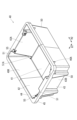
以下、図1~図13を参照して、本実施形態の第1コンテナ10(特許請求の範囲中の「SNコンテナ」に相当する)及び、第1コンテナ10と第2コンテナ40(特許請求の範囲中の「別種のSNコンテナ」に相当する)とを備えるコンテナセット100について説明する。図1に示すように、第1コンテナ10と第2コンテナ40とは、平面サイズと高さとが略同一で、組み合わせて用いることが可能となっている。
Below, with reference to Figs. 1 to 13, a first container 10 (corresponding to the "SN container" in the claims) of this embodiment and a
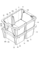
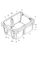
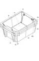
図2及び図3に示すように、第1コンテナ10及び第2コンテナ40は、共に、長方形状の上面開口10K,40Kを有する箱形をなし、長方形状の底壁11,41の長辺部から1対の長辺側壁12,42が起立し、短辺部から1対の短辺側壁13,43が起立した構造になっている。これら側壁12,13,42,43は、上側へ向かうに従って開口が拡張されるように傾斜している。なお、隣り合った側壁12,13,42,43同士の連絡部は丸みを帯びている。本実施形態では、適宜、第1コンテナ10及び第2コンテナ40の短手方向(つまり、1対の長辺側壁12,42が対向する方向)を第1水平方向H1といい、長手方向(つまり、1対の短辺側壁13,43が対向する方向)を第2水平方向H2という。
2 and 3, the
第1コンテナ10及び第2コンテナ40の側壁12,13,42,43は、上端から側方に張り出した上端フランジ壁14,44と、上端フランジ壁14,44の外周縁から垂下した垂下壁15,45と、を備えている。図4及び図5に示すように、側壁12,13,42,43と、垂下壁15,45と、の間は、複数の縦リブ16,46により連絡されている。なお、複数の縦リブ16,46の一部は、各側壁12,13,42,43の両端部に配され、下端が垂下壁15,45の下端より下方に位置する当接リブ16A,46Aとなっている。
The
図2及び図3に示すように、第1コンテナ10及び第2コンテナ40の各短辺側壁13,43には、それぞれ1対ずつ、脚部20,50が形成されている。脚部20,50は、短辺側壁13,43の一部を外側に膨出させてなり、上下方向に延びた角溝構造をなしかつ下方に向かって徐々に幅が狭くなっている。脚部20,50の下端は、底壁11,41の下面と面一になっている(図4及び図5参照)。各脚部20,50の内側は、縦溝21,51になっている。縦溝21,51の上端部は、上端フランジ壁14,44の上面に開放しており、縦溝21,51の下端は底壁11,41より若干上方位置に設けた終端壁21A,51Aによって閉塞されている。
As shown in Figures 2 and 3, a pair of
また、各短辺側壁13,43には、各縦溝21,51の横隣りにスタッキング当接部25,55が設けられている。スタッキング当接部25,55は、上端フランジ壁14,44のうち内縁部の一部を段付き状に陥没させて形成されている。
In addition, each
第1コンテナ10及び第2コンテナ40の各短辺側壁13,43では、1対の短辺側壁13,43の一方と他方とで、スタッキング当接部25,55、脚部20,50及び縦溝21,51の配置が異なっている。即ち、1対の短辺側壁13,43の一方である第1短辺側壁13A,43Aでは、横方向の両端部に脚部20,50及び縦溝21,51が配置されると共に、それら縦溝21,51より若干中央寄り位置にスタッキング当接部25,55が配置されている。これに対し、1対の短辺側壁13,43の他方である第2短辺側壁13B,43Bでは、横方向の両端部にスタッキング当接部25,55が配置されると共に、それらスタッキング当接部25,55より若干中央寄り位置に脚部20,50及び縦溝21,51が配置されている。
In each of the
そして、図6及び図7に示すように、同種のコンテナ10,40を積み上げる際に、下側のコンテナ10,40に対して上側のコンテナ10,40を180度旋回して積み上げると、上側のコンテナ10,40の各脚部20,50における下端部が、下側のコンテナ10,40のスタッキング当接部25,55に当接すると共に上側のコンテナ10,40の下端部が下側のコンテナ10,40の上面開口10K,40Kに嵌合する。これにより、コンテナ10,40が、下側のコンテナ10,40の内部に収納空間が確保されたスタッキング状態になる。
As shown in Figures 6 and 7, when stacking
一方、図8及び図9に示すように、同種のコンテナ10,40を積み上げる際に、下側のコンテナ10,40に対して上側のコンテナ10,40を同じ向きで積み上げると、上側のコンテナ10,40の脚部20,50が下側のコンテナ10,40の縦溝21,51内に挿入されて、コンテナ10,40同士の嵌合を深めたネスティング状態になる。なお、このネスティング状態では、上側のコンテナ10,40の当接リブ16A,46Aが下側のコンテナ10,40の上端フランジ壁14,44に当接して、コンテナ10,40同士が上下方向で位置決めされる。
On the other hand, as shown in Figures 8 and 9, when stacking
ここで、本実施形態では、図2及び図4に示すように、第1コンテナ10の第2短辺側壁13Bの脚部20に、上下方向の途中位置から上側を段付き状に幅広にした幅広部20Hが形成されている。幅広部20Hは、脚部20の下部に対して中央側(即ち、スタッキング当接部25と反対側)に突出していて、下端に、段差部20D(特許請求の範囲中の「第1の干渉部」に相当する)を有している。段差部20Dは、中央側へ向かうにつれて上方へ傾斜している。脚部20の幅広部20Hの内側は、縦溝21の幅広部21Hとなっている。
In this embodiment, as shown in Figs. 2 and 4, the
また、第1コンテナ10には、1対の長辺側壁12に、溝形壁部30がそれぞれ形成されている。溝形壁部30は、長辺側壁12の第2水平方向H2の中央部を内側に膨出させ、上下方向に延びた角溝状をなし、下方に向かうにつれて徐々に幅が広がっている。溝形壁部30は、底壁11に開口し、かつ、上端部が、上端閉塞壁30A(特許請求の範囲中の「第2の干渉部」に相当する)により閉塞されている。上端閉塞壁30Aは、スタッキング当接部25より下方に位置している。
In addition, the
図8に示すように、第1コンテナ10同士がネスティング状態に段積されたときは、下側の第1コンテナ10の縦溝21の幅広部21Hに、上側の第1コンテナ10の脚部20の幅広部20Hが受容されるとともに、上側の第1コンテナ10の溝形壁部30の内側に下側の第1コンテナ10の溝形壁部30が受容される。図6に示すように、第1コンテナ10同士がスタッキング状態に段積されたときは、上側の第1コンテナ10の脚部20の段差部20Dは下側の第1コンテナ10の上端フランジ壁14よりも上方に位置し、下側の第1コンテナ10の上端閉塞壁30Aは上側の第1コンテナ10の底壁11よりも下方に位置している。これら幅広部20H,21H及び溝形壁部30は第2コンテナ40には設けられていない。
As shown in FIG. 8, when the
さて、図2及び図3に示すように、第1コンテナ10と第2コンテナ40とでは、スタッキング当接部25,55、脚部20,50及び縦溝21,51の配置が略同一になっている。これにより、図1に示すように、第1コンテナ10の上に第2コンテナ40を180度旋回して(第1コンテナ10の第2短辺側壁13Bの上に第2コンテナ40の第1短辺側壁43Aを配するように)積み上げると、第2コンテナ40の脚部50における下端部が第1コンテナ10のスタッキング当接部25に当接して、スタッキング状態になる。同様に、第2コンテナ40の上に第1コンテナ10を180度旋回して(第2コンテナ40の第1短辺側壁43Aの上に第1コンテナ10の第2短辺側壁13Bを配するように)積み上げると、第1コンテナ10の脚部20における下端部が第2コンテナ40のスタッキング当接部55に当接して、スタッキング状態になる。
2 and 3, the arrangements of the stacking
しかしながら、図10及び図11に示すように、第1コンテナ10の上に第2コンテナ40を同じ向きに(第1コンテナ10の第1短辺側壁13Aの上に第2コンテナ40の第1短辺側壁43Aを配するように)積み上げようとすると、第1コンテナ10の溝形壁部30の上端閉塞壁30Aに第2コンテナ40の底壁41が当接する。これにより、第2コンテナ40が第1コンテナ10へ嵌合を深めることが防がれ、ネスティング状態になることが規制される。このとき、第2コンテナ40は、第2水平方向H2の中央部が第1コンテナ10の上端閉塞壁30Aに当接し、一端部が第1コンテナ10内に入り込んで傾いた状態になる。
However, as shown in Figures 10 and 11, when attempting to stack the
さらに、図12及び図13に示すように、第2コンテナ40の上に第1コンテナ10を同じ向きに(第2コンテナ40の第1短辺側壁43Aの上に第1コンテナ10の第1短辺側壁13Aを配するように)積み上げようとすると、第1コンテナ10の段差部20Dが第2コンテナ40の第2短辺側壁43Bの上端フランジ壁44に当接する。これにより、第1コンテナ10が第2コンテナ40へ嵌合を深めることが防がれ、ネスティング状態になることが規制される。このとき、第1コンテナ10は、第2水平方向H2の一端部が第2コンテナ40の上端フランジ壁44に当接し他端部が第1コンテナ10内に入り込んで傾いた状態になる。
Furthermore, as shown in Figs. 12 and 13, when the
つまり、コンテナセット100の第1コンテナ10と第2コンテナ40とは、相互にスタッキング状態に段積みすることが可能である一方、第1コンテナ10の段差部20D及び上端閉塞壁30Aが第2コンテナ40に干渉することでネスティング状態に段積みすることが規制される。
In other words, the
本実施形態のコンテナセット100の構成は以上である。次にコンテナセット100の作用効果について説明する。本実施形態のコンテナセット100は、例えば、以下のように用いられる。即ち、第1コンテナ10と第2コンテナ40とに別の内容物を分けて収容し、それらを混合してスタッキング状態に段積みし、保管又は運搬する。そして、内容物を取り出した後、第1コンテナ10と第2コンテナ40とをネスティング状態に段積みして、保管又は運搬する。
The above is the configuration of the container set 100 of this embodiment. Next, the effects of the container set 100 will be described. The container set 100 of this embodiment is used, for example, as follows. That is, different contents are stored separately in the
ここで、本実施形態では、第2コンテナ40の上に第1コンテナ10をネスティング状態に段積みしようとすると、第1コンテナ10の段差部20Dが第2コンテナ40の上端フランジ壁44に干渉し、ネスティング状態になることが規制される。反対に、第1コンテナ10の上に第2コンテナ40をネスティング状態に段積みしようとすると、第1コンテナ10の上端閉塞壁30Aに第2コンテナ40の底壁41が干渉し、ネスティング状態になることが規制される。
In this embodiment, when an attempt is made to stack the
これにより、第1コンテナ10と第2コンテナ40とが混ざっていることが認識されやすくなり、第1コンテナ10と第2コンテナ40との分別が容易となる。そして、事前に第1コンテナ10と第2コンテナ40とが分別されているので、再度、第1コンテナ10と第2コンテナ40とに内容物を収容する際の作業効率が向上する。
This makes it easier to recognize that the
また、第1コンテナ10と第2コンテナ40とをネスティング状態に段積みしようとすると、上側のコンテナ10,40が傾いた状態になるので、ネスティング状態になることが規制されていること、即ち、第1コンテナ10と第2コンテナ40とが混ざっていることがより認識されやすくなり、第1コンテナ10と第2コンテナ40との分別がより容易となる。
In addition, if the
さらに、第1コンテナ10の上に第2コンテナ40をネスティング状態に段積みすることを規制する溝形壁部30が、第1コンテナ10の1対の長辺側壁12の両方に配されているので、1対の長辺側壁12のどちら側から見ても第1コンテナ10であることが認識でき、第1コンテナ10と第2コンテナ40とを見た目で判別しやすくなっている。
Furthermore, grooved
しかも、第2コンテナ40を、脚部50及び縦溝51を備えるシンプルな構成とし、第1コンテナ10に段差部20D及び上端閉塞壁30Aを設けているので、既存のSNコンテナ(第2コンテナ40)の形状に合わせて、段差部20D及び上端閉塞壁30Aを備える第1コンテナ10を製造することで、本実施形態のコンテナセット100にすることができる。また、第2コンテナ40の製造型に、幅広部20H,21H及び溝形壁部30用の部品を取り付けることで、第1コンテナ10を製造することが可能であり、製造型の一部を流用することが可能となる。
In addition, since the
また、上端閉塞壁30Aがスタッキング当接部25よりも下方に位置していて、第1コンテナ10の上に第2コンテナ40をスタッキング状態に段積みしたときに、第2コンテナ40の底壁41が第1コンテナ10の上端閉塞壁30Aに当接しない。第2コンテナ40の底壁41が第1コンテナ10の上端閉塞壁30Aに当接する構成とすると、第2コンテナ40の底壁41が内容物の自重等により下方へ歪んだときに、第2コンテナ40ががたつくことが考えられるが、本実施形態によればそのような事態が防がれる。
In addition, the upper
[他の実施形態]
(1)脚部20に幅広部20Hを設けずに、脚部20及び縦溝21とは別に、上端フランジ壁14から上下方向の中間部まで延びた補助脚部及び補助溝部が側壁12,13の外側面に突出形成された構成であってもよい。
[Other embodiments]
(1) The
(2)幅広部20H(及び段差部20D)が、第1短辺側壁13Aの脚部20と第2短辺側壁13Bの脚部20との両方に設けられていてもよい(第2コンテナ40の上に配された第1コンテナ10が水平に支持され、正規のネスティング状態よりも嵌合深さが小さい構成であってもよい)。また、幅広部20Hは、脚部20の下部に対して中央側ではなく側方へ突出していてもよい。
(2) The
(3)上記実施形態では、溝形壁部30が、第1コンテナ10の長辺側壁12の中央に配されていたが、それ以外の位置(例えば、横方向の端部)に配されていてもよい。また、溝形壁部30は、1つの長辺側壁12に複数配されていてもよい(第1コンテナ10の上に配された第2コンテナ40が水平に支持され、正規のネスティング状態よりも嵌合深さが小さい構成であってもよい)。また、溝形壁部30は、1対の長辺側壁12のうち片方にのみ配されていてもよい。また、溝形壁部30は、短辺側壁13に設けられていてもよい。
(3) In the above embodiment, the
(4)第1コンテナ10の上に第2コンテナ40をネスティング状態に段積みすることと、第2コンテナ40の上に第1コンテナ10をネスティング状態に段積みすることと、との一方のみが規制される構成であってもよい。
(4) A configuration may be adopted in which only one of stacking the
なお、本明細書及び図面には、特許請求の範囲に含まれる技術の具体例が開示されているが、特許請求の範囲に記載の技術は、これら具体例に限定されるものではなく、具体例を様々に変形、変更したものも含み、また、具体例から一部を単独で取り出したものも含む。 Note that although specific examples of the technology included in the scope of the claims are disclosed in this specification and drawings, the technology described in the claims is not limited to these specific examples, but includes various modifications and variations of the specific examples, as well as parts of the specific examples taken separately.
[付記]
本明細書には、以下の特徴が含まれている。
[Additional Notes]
This specification includes the following features:
[特徴1]
上面が開放したコンテナであって、外側面に複数の脚部を有すると共に内側面に複数の縦溝を有し、コンテナ同士を180度旋回させて段積みするか、180度旋回させずに段積みするかによって、上段側のコンテナの前記脚部が下段側のコンテナの前記縦溝に受容されるネスティング状態と、上段側のコンテナの前記脚部
が下段側のコンテナの側壁の上面に当接するスタッキング状態とに変更可能であるSNコンテナにおいて、
側壁から内側又は外側に突出し、前記スタッキング状態において上下のSNコンテナと干渉しない補助突部と、
側壁を内側又は外側に陥没させ、前記ネスティング状態において、他のSNコンテナの前記補助突部を受容する補助受容部と、を有するSNコンテナ。
[Feature 1]
An SN container is an open-top container having a plurality of legs on an outer surface and a plurality of vertical grooves on an inner surface, and can be changed between a nesting state in which the legs of an upper container are received in the vertical grooves of a lower container and a stacking state in which the legs of an upper container abut against an upper surface of a side wall of a lower container, depending on whether the containers are stacked by rotating them 180 degrees or not.
An auxiliary protrusion that protrudes inward or outward from the side wall and does not interfere with the upper and lower SN containers in the stacked state;
An SN container having an auxiliary receiving portion that recesses a side wall inward or outward and receives the auxiliary protrusion of another SN container in the nested state.
[特徴2]
SNコンテナと同一サイズで、SNコンテナを上側及び下側にスタッキング状態にすることが可能な別種のSNコンテナの上に、SNコンテナを、SNコンテナの前記脚部と前記別種のSNコンテナの縦溝とが上下方向で並ぶ向きで配したときに、前記別種のSNコンテナの側壁の上面と干渉する第1の前記補助突部が、外側面から突出形成されている特徴1に記載のSNコンテナ。
[Feature 2]
An SN container as described in feature 1, in which when an SN container is placed on top of another type of SN container that is the same size as the SN container and can be stacked above and below the SN container, with the legs of the SN container and the vertical grooves of the other type of SN container aligned in the vertical direction, a first auxiliary protrusion that interferes with the upper surface of the side wall of the other type of SN container is formed to protrude from the outer surface.
[特徴3]
SNコンテナの上に、SNコンテナと同一サイズで、SNコンテナを上側及び下側にスタッキング状態にすることが可能な別種のSNコンテナを、前記別種のSNコンテナの前記脚部とSNコンテナの縦溝とが上下方向で並ぶ向きで配したときに、前記別種のSNコンテナの底壁と干渉する第2の前記補助突部が、内側面から突出形成されている特徴1又は2に記載のSNコンテナ。
[Feature 3]
An SN container as described in feature 1 or 2, in which when a different type of SN container of the same size as the SN container and which allows the SN container to be stacked above and below is placed on top of the SN container with the legs of the different type of SN container and the vertical grooves of the SN container aligned in the vertical direction, a second auxiliary protrusion that interferes with the bottom wall of the different type of SN container is formed to protrude from the inner surface.
10 第1コンテナ(SNコンテナ)
12 長辺側壁
13 短辺側壁
14 上端フランジ壁
20 脚部
20D 段差部(第1の干渉部)
20H 幅広部
21 縦溝
21H 幅広部
30 溝形壁部
30A 上端閉塞壁(第2の干渉部)
40 第2コンテナ(別種のSNコンテナ)
41 底壁
44 上端フランジ壁
50 脚部
51 縦溝
100 コンテナセット
10 First Container (SN Container)
12
20H: Wide portion 21:
40 Second Container (another type of SN container)
41
Claims (6)
SNコンテナを上側及び下側にスタッキング状態にすることが可能な別種のSNコンテナに対し、ネスティング状態にされることを規制する干渉部として、外側面から突出し、前記別種のSNコンテナの上にSNコンテナを配したときに、前記別種のSNコンテナの上面と干渉する第1の前記干渉部を備え、
前記脚部は、側壁の一部が外側に膨出しかつ下方に向かって幅狭になり、
前記脚部の内側が前記縦溝となっていて、
前記脚部の上下方向の途中位置から上側を段付き状に幅広にした幅広部を備え、SNコンテナの外面における幅広部の下端の段差部が前記第1の前記干渉部になっているSNコンテナ。 An SN container is a box-shaped container with an open top, a plurality of legs on its outer surface and a plurality of vertical grooves on its inner surface, and can be changed between a nesting state in which the legs of an upper container are received in the vertical grooves of a lower container and a stacking state in which the legs of an upper container abut against the upper surface of a side wall of a lower container, depending on whether the containers are stacked by rotating them 180 degrees or not.
a first interference portion that protrudes from an outer surface and interferes with an upper surface of a different type of SN container when the SN container is placed on top of another type of SN container that can be stacked above and below the SN container, as an interference portion that prevents the SN container from being nested;
The leg portion has a side wall that bulges outward and narrows downward,
The inner side of the leg portion is the longitudinal groove,
An SN container having a wide portion that is stepped upward from a vertical midpoint of the leg, and the step portion at the lower end of the wide portion on the outer surface of the SN container constitutes the first interference portion.
SNコンテナを上側及び下側にスタッキング状態にすることが可能な別種のSNコンテナに対し、ネスティング状態にされることを規制する干渉部として、内側面から突出し、SNコンテナの上に前記別種のSNコンテナを配したときに、前記別種のSNコンテナの底壁と干渉する第2の前記干渉部を備え、
SNコンテナの側壁の一部を内側に膨出しかつ下方に向かって幅広になり、SNコンテナの底壁に開口した溝形壁部を備え、前記溝形壁部の上端部が前記第2の前記干渉部になっていて、
前記溝形壁部は、SNコンテナの第1水平方向で対向する1対の側壁のうち、前記第1水平方向と直交する第2水平方向の同一位置に、それぞれ配されているSNコンテナ。 An SN container is a box-shaped container with an open top, a plurality of legs on its outer surface and a plurality of vertical grooves on its inner surface, and can be changed between a nesting state in which the legs of an upper container are received in the vertical grooves of a lower container and a stacking state in which the legs of an upper container abut against the upper surface of a side wall of a lower container, depending on whether the containers are stacked by rotating them 180 degrees or not.
a second interference portion that protrudes from an inner surface and interferes with a bottom wall of a different type of SN container when the SN container is placed on top of another type of SN container that can be stacked above and below the SN container as an interference portion that prevents the SN container from being nested;
A part of the side wall of the SN container is bulged inward and widened downward, and is provided with a grooved wall portion that opens into the bottom wall of the SN container, and an upper end of the grooved wall portion is the second interference portion,
The groove-shaped wall portions are arranged at the same positions in a second horizontal direction perpendicular to the first horizontal direction on a pair of side walls opposing each other in a first horizontal direction of the SN container.
SNコンテナを上側及び下側にスタッキング状態にすることが可能な別種のSNコンテナに対し、ネスティング状態にされることを規制する干渉部を備え、
前記干渉部は、SNコンテナの平面形状の縦方向又は横方向の一位置で前記別種のSNコンテナの上面又は底壁と干渉し、上側に配されたSNコンテナ又は前記別種のSNコンテナを傾斜させるSNコンテナ。 An SN container is a box-shaped container with an open top, a plurality of legs on its outer surface and a plurality of vertical grooves on its inner surface, and can be changed between a nesting state in which the legs of an upper container are received in the vertical grooves of a lower container and a stacking state in which the legs of an upper container abut against the upper surface of a side wall of a lower container, depending on whether the containers are stacked by rotating them 180 degrees or not.
The SN container is provided with an interference portion that prevents another type of SN container from being nested with another type of SN container that can be stacked above and below the SN container;
The interference portion interferes with the top or bottom wall of the other type of SN container at a certain vertical or horizontal position in the planar shape of the SN container, thereby tilting the SN container or the other type of SN container arranged above.
側壁から内側又は外側に突出し、前記スタッキング状態において上下のSNコンテナと干渉しない補助突部と、
側壁を内側又は外側に陥没させ、前記ネスティング状態において、他のSNコンテナの前記補助突部を受容する補助受容部と、を有し、
SNコンテナを上側及び下側にスタッキング状態にすることが可能な別種のSNコンテナに対し、スタッキング状態からSNコンテナと別種のSNコンテナとの一方を180度旋回した状態にされると、前記補助突部が前記別種のSNコンテナと干渉して、上側に配されたSNコンテナ又は前記別種のSNコンテナを傾斜させるSNコンテナ。 An SN container is an open-top container having a plurality of legs on an outer surface and a plurality of vertical grooves on an inner surface, and can be changed between a nesting state in which the legs of an upper container are received in the vertical grooves of a lower container and a stacking state in which the legs of an upper container abut against an upper surface of a side wall of a lower container, depending on whether the containers are stacked by rotating them 180 degrees or not.
An auxiliary protrusion that protrudes inward or outward from the side wall and does not interfere with the upper and lower SN containers in the stacked state;
and an auxiliary receiving portion that receives the auxiliary protrusion of another SN container in the nested state by recessing a side wall inward or outward,
An SN container in which, for a different type of SN container capable of being stacked above and below an SN container, when either the SN container or the different type of SN container is rotated 180 degrees from the stacked state, the auxiliary protrusion interferes with the different type of SN container, causing the SN container placed above or the different type of SN container to tilt.
前記第1と第2のSNコンテナは、互いにスタッキング状態に段積み可能であり、かつ、前記第1のSNコンテナの上に前記第2のSNコンテナを配したときと前記第2のSNコンテナの上に前記第1のSNコンテナを配したときとの少なくとも一方で、上側に配された第1又は第2のSNコンテナが傾斜して、ネスティング状態にすることが規制されるコンテナセット。 A container set including two types of SN containers, first and second, each having a box shape with an open top, a plurality of legs on its outer surface and a plurality of vertical grooves on its inner surface, wherein the SN containers of the same type are stacked with or without being rotated 180 degrees, so that the container set can be changed between a nesting state in which the legs of the SN container on the upper tier are received in the vertical grooves of the SN container on the lower tier and a stacking state in which the legs of the SN container on the upper tier abut against the upper surface of the side wall of the SN container on the lower tier,
The first and second SN containers are capable of being stacked on top of each other, and when the second SN container is placed on top of the first SN container or when the first SN container is placed on top of the second SN container, the first or second SN container placed on top is prevented from tilting and entering a nested state.
SNコンテナを上側及び下側にスタッキング状態にすることが可能でありかつSNコンテナと平面形状の大きさが同一の別種のSNコンテナに対し、スタッキング状態からSNコンテナと別種のSNコンテナとの一方を180度旋回させると、上側に配されるSNコンテナ又は前記別種のSNコンテナを傾斜させてネスティング状態にされることを規制する干渉部を備えるSNコンテナ。 An SN container is a box-shaped container with an open top, a plurality of legs on its outer surface and a plurality of vertical grooves on its inner surface, and can be changed between a nesting state in which the legs of an upper container are received in the vertical grooves of a lower container and a stacking state in which the legs of an upper container abut against the upper surface of a side wall of a lower container, depending on whether the containers are stacked by rotating them 180 degrees or not.
An SN container capable of being stacked above and below the SN container, and having an interference portion that prevents the SN container placed above or the other type of SN container from being tilted and placed in a nested state when either the SN container or the other type of SN container is rotated 180 degrees from a stacked state relative to a different type of SN container having the same planar shape size as the SN container.
Priority Applications (1)
| Application Number | Priority Date | Filing Date | Title |
|---|---|---|---|
| JP2021072075A JP7660880B2 (en) | 2021-04-21 | 2021-04-21 | SN containers and container sets |
Applications Claiming Priority (1)
| Application Number | Priority Date | Filing Date | Title |
|---|---|---|---|
| JP2021072075A JP7660880B2 (en) | 2021-04-21 | 2021-04-21 | SN containers and container sets |
Publications (2)
| Publication Number | Publication Date |
|---|---|
| JP2022166689A JP2022166689A (en) | 2022-11-02 |
| JP7660880B2 true JP7660880B2 (en) | 2025-04-14 |
Family
ID=83851536
Family Applications (1)
| Application Number | Title | Priority Date | Filing Date |
|---|---|---|---|
| JP2021072075A Active JP7660880B2 (en) | 2021-04-21 | 2021-04-21 | SN containers and container sets |
Country Status (1)
| Country | Link |
|---|---|
| JP (1) | JP7660880B2 (en) |
Citations (6)
| Publication number | Priority date | Publication date | Assignee | Title |
|---|---|---|---|---|
| JP2000085775A (en) | 1998-09-16 | 2000-03-28 | Mitsubishi Plastics Ind Ltd | Transport container |
| JP2001097381A (en) | 1999-09-30 | 2001-04-10 | Sanko Co Ltd | Transport container |
| JP2004284640A (en) | 2003-03-20 | 2004-10-14 | Gifu Plast Ind Co Ltd | Transportation container |
| WO2005028321A1 (en) | 2003-09-18 | 2005-03-31 | Yoshihisa Huruta | Article storage case |
| JP2007099321A (en) | 2005-09-30 | 2007-04-19 | Sekisui Plastics Co Ltd | Transport container |
| US20080296194A1 (en) | 2007-05-30 | 2008-12-04 | Norseman Plastics Ltd. | Nestable and stackable container for the transport of heavy baked items |
-
2021
- 2021-04-21 JP JP2021072075A patent/JP7660880B2/en active Active
Patent Citations (6)
| Publication number | Priority date | Publication date | Assignee | Title |
|---|---|---|---|---|
| JP2000085775A (en) | 1998-09-16 | 2000-03-28 | Mitsubishi Plastics Ind Ltd | Transport container |
| JP2001097381A (en) | 1999-09-30 | 2001-04-10 | Sanko Co Ltd | Transport container |
| JP2004284640A (en) | 2003-03-20 | 2004-10-14 | Gifu Plast Ind Co Ltd | Transportation container |
| WO2005028321A1 (en) | 2003-09-18 | 2005-03-31 | Yoshihisa Huruta | Article storage case |
| JP2007099321A (en) | 2005-09-30 | 2007-04-19 | Sekisui Plastics Co Ltd | Transport container |
| US20080296194A1 (en) | 2007-05-30 | 2008-12-04 | Norseman Plastics Ltd. | Nestable and stackable container for the transport of heavy baked items |
Also Published As
| Publication number | Publication date |
|---|---|
| JP2022166689A (en) | 2022-11-02 |
Similar Documents
| Publication | Publication Date | Title |
|---|---|---|
| JP7660880B2 (en) | SN containers and container sets | |
| JP7378726B2 (en) | container | |
| JP6537333B2 (en) | Folding container | |
| JP5727889B2 (en) | Lid member | |
| JP4789184B2 (en) | SN container | |
| JP4077944B2 (en) | Box container | |
| JP7134482B2 (en) | folding container | |
| JP2019099175A (en) | Folding container | |
| JP5435630B2 (en) | Folding container | |
| JP3923231B2 (en) | Mating container | |
| JP4142864B2 (en) | Folding container | |
| JP6333641B2 (en) | Container stacking engagement structure | |
| JP4931075B2 (en) | Folding container | |
| JP2021041987A (en) | container | |
| JP7462301B2 (en) | Folding container | |
| JP2009040462A (en) | Folding container | |
| JP4934539B2 (en) | Folding container | |
| JP3842638B2 (en) | Folding container | |
| JP4077943B2 (en) | Box container | |
| JP3958475B2 (en) | Transport container | |
| JP4745910B2 (en) | Transport container | |
| JP2002128071A (en) | Folding container | |
| JP5420496B2 (en) | Folding container | |
| JP2023120000A (en) | Containers and container sets | |
| JP2025167287A (en) | container |
Legal Events
| Date | Code | Title | Description |
|---|---|---|---|
| A621 | Written request for application examination |
Free format text: JAPANESE INTERMEDIATE CODE: A621 Effective date: 20240226 |
|
| A977 | Report on retrieval |
Free format text: JAPANESE INTERMEDIATE CODE: A971007 Effective date: 20240805 |
|
| A131 | Notification of reasons for refusal |
Free format text: JAPANESE INTERMEDIATE CODE: A131 Effective date: 20240910 |
|
| A521 | Request for written amendment filed |
Free format text: JAPANESE INTERMEDIATE CODE: A523 Effective date: 20241025 |
|
| A131 | Notification of reasons for refusal |
Free format text: JAPANESE INTERMEDIATE CODE: A131 Effective date: 20250121 |
|
| A521 | Request for written amendment filed |
Free format text: JAPANESE INTERMEDIATE CODE: A523 Effective date: 20250129 |
|
| TRDD | Decision of grant or rejection written | ||
| A01 | Written decision to grant a patent or to grant a registration (utility model) |
Free format text: JAPANESE INTERMEDIATE CODE: A01 Effective date: 20250311 |
|
| A61 | First payment of annual fees (during grant procedure) |
Free format text: JAPANESE INTERMEDIATE CODE: A61 Effective date: 20250326 |
|
| R150 | Certificate of patent or registration of utility model |
Ref document number: 7660880 Country of ref document: JP Free format text: JAPANESE INTERMEDIATE CODE: R150 |