JP7659397B2 - Image processing device, autonomous mobile robot - Google Patents
Image processing device, autonomous mobile robot Download PDFInfo
- Publication number
- JP7659397B2 JP7659397B2 JP2021016259A JP2021016259A JP7659397B2 JP 7659397 B2 JP7659397 B2 JP 7659397B2 JP 2021016259 A JP2021016259 A JP 2021016259A JP 2021016259 A JP2021016259 A JP 2021016259A JP 7659397 B2 JP7659397 B2 JP 7659397B2
- Authority
- JP
- Japan
- Prior art keywords
- area
- cell
- detection
- image processing
- processing device
- Prior art date
- Legal status (The legal status is an assumption and is not a legal conclusion. Google has not performed a legal analysis and makes no representation as to the accuracy of the status listed.)
- Active
Links
- 238000012545 processing Methods 0.000 title claims description 30
- 238000001514 detection method Methods 0.000 claims description 88
- 238000006073 displacement reaction Methods 0.000 claims description 20
- 238000003384 imaging method Methods 0.000 claims description 14
- 101100229939 Mus musculus Gpsm1 gene Proteins 0.000 description 22
- 238000000034 method Methods 0.000 description 15
- 238000010586 diagram Methods 0.000 description 10
- 238000004891 communication Methods 0.000 description 3
- 239000010408 film Substances 0.000 description 2
- 230000005484 gravity Effects 0.000 description 2
- 238000005286 illumination Methods 0.000 description 2
- 239000000463 material Substances 0.000 description 2
- 239000011159 matrix material Substances 0.000 description 2
- GWEVSGVZZGPLCZ-UHFFFAOYSA-N Titan oxide Chemical compound O=[Ti]=O GWEVSGVZZGPLCZ-UHFFFAOYSA-N 0.000 description 1
- 239000011358 absorbing material Substances 0.000 description 1
- XAGFODPZIPBFFR-UHFFFAOYSA-N aluminium Chemical compound [Al] XAGFODPZIPBFFR-UHFFFAOYSA-N 0.000 description 1
- 229910052782 aluminium Inorganic materials 0.000 description 1
- 238000013461 design Methods 0.000 description 1
- 239000011888 foil Substances 0.000 description 1
- 239000003550 marker Substances 0.000 description 1
- 238000012986 modification Methods 0.000 description 1
- 230000004048 modification Effects 0.000 description 1
- 238000012907 on board imaging Methods 0.000 description 1
- 239000010409 thin film Substances 0.000 description 1
- OGIDPMRJRNCKJF-UHFFFAOYSA-N titanium oxide Inorganic materials [Ti]=O OGIDPMRJRNCKJF-UHFFFAOYSA-N 0.000 description 1
Images


Landscapes
- Control Of Position, Course, Altitude, Or Attitude Of Moving Bodies (AREA)
Description
本発明は、画像処理装置、自律移動ロボットに関するものである。 The present invention relates to an image processing device and an autonomous mobile robot.
従来から、下記特許文献1に記載の画像処理装置、移動ロボットの制御システム、および移動ロボットの制御方法が知られている。この画像処理装置は、二次元平面上に、正方形又は長方形からなるセルであって、照射された光を反射可能な第一セルと照射された光を反射不能な第二セルとを、a×a、又はa×b(ただし、a、b=3,4,5,6,…)の行列配置して構成される被検出体と、光を照射する照射部と、前記照射部から照射された光が前記被検出体を構成する前記第一セルと前記第二セルに照射された後、前記第一セルから反射された光をカメラで撮像する撮像部と、前記撮像部によって撮像された撮像データに基づいて、前記被検出体に設定された情報を取得する算出部と、を備える検出部と、を備えている。
Conventionally, an image processing device, a control system for a mobile robot, and a control method for a mobile robot described in the following
上記のように、複数のセルが二次元平面上に配置された被検出部は、例えば、自律移動ロボットの移動経路などに設置され、自律移動ロボットを誘導するサインポストなどとして使用される。ところで、このような被検出部を設置するとき、被検出部がロール方向に傾いてしまう場合がある。そうすると、画像処理装置による被検出部の読み取りが困難になる虞がある。 As described above, a detectable part in which multiple cells are arranged on a two-dimensional plane is installed, for example, on the movement path of an autonomous mobile robot and used as a sign post to guide the autonomous mobile robot. However, when installing such a detectable part, the detectable part may be tilted in the roll direction. This may make it difficult for an image processing device to read the detectable part.
本発明は、上記課題に鑑みてなされたものであり、被検出部のロール方向の傾きを把握し、被検出部の読み取り確度の低下を抑制できる画像処理装置、自律移動ロボットの提供を目的とする。 The present invention was made in consideration of the above problems, and aims to provide an image processing device and an autonomous mobile robot that can grasp the inclination of the detected part in the roll direction and suppress a decrease in the reading accuracy of the detected part.
上記の課題を解決するために、本発明の画像処理装置は、複数のセルが二次元平面上に配置された被検出部を検出する画像処理装置であって、前記被検出部における、一次方向に並んだ2つのセルの前記一次方向と直交する二次方向における相対的な変位量と、前記二次方向に並んだ2つセルの前記一次方向における相対的な変位量と、に基づいて、前記被検出部の傾きを算出する算出部を有する。 In order to solve the above problem, the image processing device of the present invention is an image processing device that detects a detectable portion in which a plurality of cells are arranged on a two-dimensional plane, and has a calculation unit that calculates the inclination of the detectable portion based on the relative displacement amount in a secondary direction perpendicular to the primary direction of two cells aligned in a primary direction in the detectable portion, and the relative displacement amount in the primary direction of two cells aligned in the secondary direction.
また、本発明の自律移動ロボットは、複数のセルが二次元平面上に配置された被検出部を有する標識を、搭載した撮像部で読み取り、前記標識に誘導されて移動する自律移動ロボットであって、先に記載された画像処理装置を備える。 The autonomous mobile robot of the present invention is an autonomous mobile robot that reads a sign having a detectable portion in which multiple cells are arranged on a two-dimensional plane using an on-board imaging unit, and moves while being guided by the sign, and is equipped with the image processing device described above.
本発明によれば、被検出部のロール方向の傾きを把握し、被検出部の読み取り確度の低下を抑制できる。 According to the present invention, it is possible to grasp the inclination of the detected part in the roll direction and prevent a decrease in the reading accuracy of the detected part.
以下、本発明の実施形態について図面を参照して説明する。 The following describes an embodiment of the present invention with reference to the drawings.
(第1実施形態)
図1は、本発明の第1実施形態における自律移動ロボット1が移動する様子を上方から視た模式図である。
図1に示すように、自律移動ロボット1は、移動経路10に沿って配置された複数のサインポストSPを、ロボット本体20に搭載した撮像部26で順に読み取りながら移動する。つまり、自律移動ロボット1は、複数のサインポストSPに誘導されて移動経路10を移動する。
First Embodiment
FIG. 1 is a schematic diagram showing the movement of an autonomous
1, the autonomous
ここで「サインポスト」とは、サイン(標識)を有して、移動経路10あるいは移動経路10近傍の所定の場所に置かれた構造体を言う。サインは、その構造体の識別情報(ターゲットID)を含む。本実施形態のサインは、後述する図3に示すように、光を反射可能な第一セル(セルC11、C13…)と、光を反射不能な第二セル(セルC12、C21…)とが、二次元平面上に配置された被検出部Cである。なお、サインは、1次元コード(バーコード)や、その他の2次元コードなどであっても構わない。
Here, a "signpost" refers to a structure having a sign (marker) and placed at a predetermined location on the
図2は、本発明の第1実施形態における自律移動ロボット1の構成を示すブロック図である。
図2に示すように、自律移動ロボット1は、サインポスト検出部21(画像処理装置)と、駆動部22と、制御部23と、通信部24と、を備えている。
FIG. 2 is a block diagram showing the configuration of the autonomous
As shown in FIG. 2, the autonomous
サインポスト検出部21は、照射部25と、2つの撮像部26と、算出部27と、を有する。また、駆動部22は、モータ制御部28と、2つのモータ29と、左右の駆動輪20L,20Rと、を有する。なお、サインポスト検出部21及び駆動部22の構成は、あくまで一例であって、他の構成であっても構わない。
The sign
照射部25は、自律移動ロボット1の進行方向の前面の中央位置に取り付けられ、例えば、赤外LED光を前方に照射する。赤外LED光は、工場内などの暗所や可視光の強い場所等に好適である。なお、照射部25は、赤外LED光以外の検出光を照射する構成であっても構わない。
The
2つの撮像部26は、サインポスト検出部21の左右に配置されている。2つの撮像部26は、例えば、赤外線フィルタを組み合わせたカメラが用いられ、サインポストSPで反射された反射光(赤外LED光)を撮像する。
The two
算出部27は、2つの撮像部26から送信された撮像画像に基づき、2値化処理を行うことで白黒からなる2値化画像データを形成し、さらに2値化された画像データを用いて三角測量(2つの撮像部26の撮像画像の差分を用いた三角測量)による演算を行うことで、自律移動ロボット1に対してサインポストSPがどの様な距離(距離Z)と方向(角度θ)に位置するのかを算出する。
The
なお、算出部27は、撮像画像に複数のサインポストSPが含まれる場合、サインポストSPの識別情報(ターゲットID)を検出して目標とするサインポストSPを選択し、目標とするサインポストSPまでの距離Zと角度θとを算出する。
When the captured image includes multiple sign posts SP, the
駆動輪20Lは、自律移動ロボット1の進行方向に対して左側に設けられている。駆動輪20Rは、自律移動ロボット1の進行方向に対して右側に設けられている。なお、自律移動ロボット1は、自律移動ロボット1の姿勢を安定させるために、駆動輪20L,20R以外の車輪を有していてもよい。
モータ29は、モータ制御部28の制御に応じて、左右の駆動輪20L,20Rを回転させる。
The
モータ制御部28は、制御部23から入力される角速度指令値に基づいて、左右のモータ29に対して電力を供給する。左右のモータ29がモータ制御部28から供給される電力に応じた角速度で回転することにより、自律移動ロボット1が前進または後進する。また、左右のモータ29の角速度に差を生じさせることにより、自律移動ロボット1の進行方向が変更される。
The
制御部23は、サインポスト検出部21によってサインポストSPから読み取った情報に基づいて、駆動部22を制御する。
The
図1に示す移動例では、自律移動ロボット1は、移動経路10の左側から一定の距離を保って移動する。自律移動ロボット1は、移動経路10の左側から一定の距離を保つためにサインポストSPに対する距離Xrefを決定すると共に、検出したサインポストSPまでの距離Zと角度θとを取得し、距離Zと角度θとが予め定められた条件を満たす進行方向を算出する。
In the example of movement shown in FIG. 1, the autonomous
角度θは、自律移動ロボット1の進行方向と、検出されたサインポストSPの方向とが成す角である。自律移動ロボット1は、サインポストSPと目標経路との距離がXrefとなるように進行する。自律移動ロボット1は、誘導されるサインポストSP(例えばサインポストSP1)までの距離Zが予め定められた閾値より近くなると、目標を次のサインポストSP(例えばサインポストSP2)に切り替えて移動する。なお、サインポストSP2は、ロール方向に傾いた状態を表している。ロール方向とは、サインポストSP(具体的には後述する被検出部C)の面直方向に延びる軸をロール軸としたとき、そのロール軸を周回する方向をいう。
The angle θ is the angle between the traveling direction of the autonomous
図3は、本発明の第1実施形態におけるサインポスト検出部21が読み取るサインポストSPの被検出部Cの一例を示す正面図である。
図3に示すように、サインポストSPは、赤外LED光を反射可能な第一セル(セルC11、C13…)と、赤外LED光を反射不能な第二セル(セルC12、C21…)とが、二次元平面上に配置された被検出部Cを備えている。
FIG. 3 is a front view showing an example of a detection target portion C of a sign post SP that is read by the sign
As shown in Figure 3, the sign post SP has a detection area C in which first cells (cells C11, C13, ...) capable of reflecting infrared LED light and second cells (cells C12, C21, ...) that cannot reflect infrared LED light are arranged on a two-dimensional plane.
本実施形態の被検出部Cは、3行×3列の行列状のパターンからなる。具体的には、被検出部Cは、1行1列目のセルC11(第一セル)と、1行2列目のセルC12(第二セル)と、1行3列目のセルC13(第一セル)と、2行1列目のセルC21(第二セル)と、2行2列目のセルC22(第一セル)と、2行3列目のセルC23(第二セル)と、3行1列目のセルC31(第一セル)と、3行2列目のセルC32(第二セル)と、3行3列目のセルC33(第一セル)と、を備える。
The detection target portion C of this embodiment is composed of a matrix pattern of 3 rows x 3 columns. Specifically, the detection target portion C includes cell C11 (first cell) in
第一セル(セルC11、C13、C22、C31、C33)は、例えば、アルミニウム箔や酸化チタンの薄膜等の赤外LED光の反射率が高い材料によって形成されている。第二セル(セルC12、C21、C23、C32)は、例えば、赤外カットフィルムや偏光フィルム、赤外線吸収材、黒色フェルト等の赤外LED光の反射率が低い材料によって形成されている。 The first cells (cells C11, C13, C22, C31, and C33) are formed from a material with high reflectance to infrared LED light, such as aluminum foil or a thin film of titanium oxide. The second cells (cells C12, C21, C23, and C32) are formed from a material with low reflectance to infrared LED light, such as an infrared cut film, a polarizing film, an infrared absorbing material, or black felt.
算出部27は、撮像部26が撮像した撮像画像に含まれる被検出部Cに対して第一走査SC1及び第二走査SC2をすることで、サインポストSPを検出する。第一走査SC1では、例えば、1行目の「白、黒、白」で配置されたセルC11(第一セル)、セルC12(第二セル)、及びセルC13(第一セル)を検出する。第二走査SC2では、例えば、1列目の「白、黒、白」で配置されたセルC11(第一セル)、セルC21(第二セル)、及びセルC31(第一セル)を検出する。
The
白を「1」、黒を「0(ゼロ)」とするバイナリーコードで表現すると「白、黒、白」は「1、0、1」と示すことができ、算出部27は、第一走査SC1による「1、0、1」と、第二走査SC2による「1、0、1」の読み取りが成功したとき、サインポストSPを検出する。
When expressed in binary code with white being "1" and black being "0 (zero)," "white, black, white" can be expressed as "1, 0, 1." The
算出部27は、被検出部Cの残りのセル(2行2列目のセルC22と、2行3列目のセルC23と、3行2列目のセルC32と、3行3列目のセルC33)からサインポストSPの識別情報(ターゲットID)を読み取る。図3に示す例では、4ビットの情報で、算出部27にサインポストSPの識別情報を読み取らせることができる。
The
以上のように、被検出部Cは、サインポスト検出部21が被検出部Cを検出するための被検出領域C10と、サインポスト検出部21が被検出部Cを識別するための識別領域20Cと、を有する。被検出領域C10には、被検出部Cの1行目のセルC11、セルC12、及びセルC13からなるスタートバーC10a(第一領域)と、被検出部Cの1列目のセルC11、セルC21、及びセルC31からなるストップバーC10b(第二領域)と、が含まれる。
As described above, the detectable portion C has a detectable area C10 in which the sign
スタートバーC10aとストップバーC10bは、被検出部Cの1行1列目において一部重なっている。つまり、1行1列目のセルC11は、スタートバーC10a及びストップバーC10bの一部を形成している。識別領域20Cには、2行2列目のセルC22と、2行3列目のセルC23と、3行2列目のセルC32と、3行3列目のセルC33と、が含まれる。 The start bar C10a and the stop bar C10b overlap partially in the first row and first column of the detected portion C. In other words, cell C11 in the first row and first column forms part of the start bar C10a and the stop bar C10b. The identification area 20C includes cell C22 in the second row and second column, cell C23 in the second row and third column, cell C32 in the third row and second column, and cell C33 in the third row and third column.
図2に戻り、通信部24は、図示しない上位システムと通信を行う。図示しない上位システムは、例えば、移動経路10における自律移動ロボット1の現在位置に基づいて、検出すべきサインポストSPの識別情報(ターゲットID)を自律移動ロボット1に提供する。
Returning to FIG. 2, the
以下、図4~図6を参照して、上述した自律移動ロボット1(サインポスト検出部21)の画像処理の流れについて具体的に説明する。以下の説明において、特に断りが無い限り、自律移動ロボット1の画像処理に関する計算は算出部27が行う。なお、自律移動ロボット1の走行制御に関する計算は制御部23が行う。
The image processing flow of the autonomous mobile robot 1 (signpost detection unit 21) described above will be specifically explained below with reference to Figures 4 to 6. In the following explanation, unless otherwise specified, calculations related to image processing of the autonomous
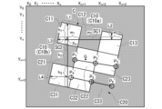
図4及び図5は、本発明の第1実施形態における自律移動ロボット1の画像処理を示すフロー図である。なお、図4及び図5に示す丸中数字の1~2は、図4及び図5に示す両フローの繋がりを示している。図6は、本発明の第1実施形態におけるロール方向に傾いた被検出部Cを含む撮像画像を示すイメージ図である。
算出部27は、図6に示す撮像画像から被検出部C(サイン)を検出する処理を開始する(ステップS1)。なお、以下の処理は、撮像部26が撮像する撮像画像の1フレーム(1枚)ごとに実行する。
Figures 4 and 5 are flow diagrams showing image processing of the autonomous
The
先ず、図6に示すように、撮像画像の座標(X0,Y0)からX軸方向に1行ずつ走査し(上述した第一走査SC1)、Yn行目の白(第一セル)、黒(第二セル)、白(第一セル)の幅w1,w2,w3を調べる(ステップS2)。なお、撮像画像においては、撮像画像の左上角が原点座標(X0,Y0)とされ、横方向がX軸方向(一次方向)とされて、撮像画像の縦方向がY軸方向(二次方向)とされている。また、撮像画像の横方向右側がX軸方向の+側であり、撮像画像の縦方向下側がY軸方向の+側である。 First, as shown in Fig. 6, the captured image is scanned row by row in the X-axis direction from the coordinates ( X0 , Y0 ) (first scan SC1 described above), and the widths w1 , w2 , and w3 of white (first cell), black (second cell), and white (first cell) in the Ynth row are checked (step S2). Note that in the captured image, the upper left corner of the captured image is set to the origin coordinates ( X0 , Y0 ), the horizontal direction is set to the X-axis direction (primary direction), and the vertical direction of the captured image is set to the Y-axis direction (secondary direction). Also, the right side of the horizontal direction of the captured image is the + side in the X-axis direction, and the lower side of the vertical direction of the captured image is the + side in the Y-axis direction.
次に、幅w1,w2,w3が等間隔である白、黒、白の並びがあるか否かを判断する(ステップS3)。なお、幅w1,w2,w3が等間隔である白、黒、白の並びがあるとは、最初に検出された白の幅w1を基準とした場合に、その後に検出された黒の幅w2、白の幅w3が、例えば幅w1の±10%の範囲内にあることをいう。 Next, it is determined whether or not there is a sequence of white, black, white with the widths w1 , w2 , and w3 spaced equally apart (step S3). Note that the presence of a sequence of white, black , and white with the widths w1 , w2, and w3 spaced equally apart means that, when the initially detected white width w1 is taken as a reference, the subsequently detected black width w2 and white width w3 are within a range of, for example, ±10% of the width w1 .
ステップS3で「YES」の場合、Yn行目のXn~Xn+3までをスタートバーC10aであるとみなし、スタートバーC10aを構成する白と黒の境界位置Xn~Xn+3を記憶しておく(ステップS4)。
なお、ステップS3で「NO」の場合、変数nを+1カウントした後、ステップS2に戻り、次のYn+1行目の白(第一セル)、黒(第二セル)、白(第一セル)の幅w1,w2,w3を調べる。
If "YES" in step S3, Xn to Xn +3 on the Ynth row are regarded as the start bar C10a, and the white and black boundary positions Xn to Xn +3 that constitute the start bar C10a are stored (step S4).
If the answer is "NO" in step S3, the variable n is counted up by +1, and then the process returns to step S2 to check the widths w1 , w2 , and w3 of white (first cell), black (second cell), and white (first cell) in the next Yn +1th row.
ステップS4の次は、幅w1のX軸方向の中心位置XSを求める(ステップS5)。そして、中心位置XSを含む列を、Y軸方向にYnの位置から走査(上述した第二走査SC2)する(ステップS6)。次に、ステップS6での第二走査SC2において、白、黒、白の並びがあるか否かを判断する(ステップS7)。 After step S4, the center position Xs of the width w1 in the X-axis direction is found (step S5). Then, the row including the center position Xs is scanned in the Y-axis direction from the position Yn (second scan SC2 described above) (step S6). Next, in the second scan SC2 in step S6, it is determined whether or not there is a white, black, white sequence (step S7).
ステップS7で「YES」の場合、XS列目の白、黒、白をストップバーC10bであるとみなし、第二走査SC2において自明となった黒(セルC21)のY軸方向の高さh2、白(セルC31)のY軸方向の高さh3から、黒(セルC21)のY軸方向の中心位置Yn+1、白(セルC31)のY軸方向の中心位置Yn+2を求める(ステップS8)。
なお、ステップS7で「NO」の場合、変数nを+1カウントした後、ステップS2に戻り、次のYn+1行目の白(第一セル)、黒(第二セル)、白(第一セル)の幅w1,w2,w3を調べる。
If the answer is "YES" in step S7, the white, black, and white in the XSth column are regarded as a stop bar C10b, and from the height h2 of the black (cell C21) in the Y axis direction and the height h3 of the white (cell C31) in the Y axis direction, which became obvious in the second scan SC2 , the central position Yn +1 of the black (cell C21) and the central position Yn+2 of the white (cell C31) in the Y axis direction are determined (step S8).
If the answer is "NO" in step S7, the variable n is counted up by +1, and then the process returns to step S2 to check the widths w1 , w2 , and w3 of white (first cell), black (second cell), and white (first cell) in the next Yn +1th row.
ステップS8の次は、図6に示す長さL1,L2,L3,L4を走査し、その長さを求める(図5のステップS21)。長さL1は、座標(XS,Yn)からY軸方向-側(紙面上側)に走査し、白黒の境界に至るまでのY軸方向の距離である。長さL2は、座標(Xn+2+w3/2,Yn)からY軸方向-側(紙面上側)に走査し、白黒の境界に至るまでのY軸方向の距離である。長さL3は、座標(XS,Yn)からX軸方向-側(紙面左側)に走査し、白黒の境界に至るまでのX軸方向の距離である。長さL4は、座標(XS,Yn+2)からX軸方向-側(紙面左側)に走査し、白黒の境界に至るまでのX軸方向の距離である。 After step S8, lengths L1, L2, L3, and L4 shown in FIG. 6 are scanned to determine the lengths (step S21 in FIG. 5). Length L1 is the distance in the Y-axis direction from the coordinate ( Xs , Yn ) to the negative side in the Y-axis direction (upper side of the paper) until the black-white boundary is reached. Length L2 is the distance in the Y-axis direction from the coordinate (Xn +2 + w3 /2, Yn ) to the negative side in the Y-axis direction (upper side of the paper) until the black-white boundary is reached. Length L3 is the distance in the X-axis direction from the coordinate ( Xs , Yn ) to the negative side in the X-axis direction (left side of the paper) until the black-white boundary is reached. Length L4 is the distance in the X-axis direction from the coordinate ( Xs , Yn +2 ) to the negative side in the X-axis direction (left side of the paper) until the black-white boundary is reached.
ステップS21の次は、長さL1,L2からX軸方向の変化量に対する傾きaYを計算し、長さL3,L4からY軸方向の変化量に対する傾きaXを計算する(ステップS22)。つまり、算出部27は、被検出部Cにおける、X軸方向に並んだ2つのセルC11,C13のX軸方向と直交するY軸方向における相対的な変位量(L1-L2)と、Y軸方向に並んだ2つセルC11,C31のX軸方向における相対的な変位量(L3-L4)と、に基づいて、被検出部Cの傾きaX,aYを算出する。
After step S21, the
ステップS22の次は、傾きaX,aYを用い、下式(1)~(4)により、被検出部Cの識別領域C20の各座標P1~P6に対し、回転後のP1´~P6´(白黒の境界座標)を算出する(ステップS23)。なお、PNは、被検出部Cの傾きが無いとした場合(傾きをゼロとした場合)の座標である。PN´は、被検出部Cの傾いた状態(ロール回転後)の座標である。
PN=(XN,YN) …(1)
PN´=(XN´,YN´) …(2)
XN´=XN+aX(YN-Yn) …(3)
YN´=YN+aY(XN-XS) …(4)
After step S22, the inclinations aX and aY are used to calculate P1 ' to P6' (black and white boundary coordinates) after rotation for each coordinate P1 to P6 of the identification area C20 of the detection target C using the following formulas (1) to ( 4 ) (step S23). Note that PN is the coordinate when there is no inclination of the detection target C (when the inclination is set to zero), and PN ' is the coordinate when the detection target C is in an inclined state (after roll rotation).
P N = (X N , Y N )...(1)
P N ′=(X N ′, Y N ′) …(2)
X N ′=X N +a X (Y N -Y n )…(3)
Y N '=Y N +a Y (X N -X S )...(4)
ステップS23の次は、識別領域C20の4箇所(セルC22、C23、C32、C33)を下記1.~4.のとおり走査し、各セルが白黒のいずれであるか調べる(ステップS24)。
1. 始点P1´から終点P2´とする箇所
2. 始点P2´から終点P3´とする箇所
3. 始点P4´から終点P5´とする箇所
4. 始点P5´から終点P6´とする箇所
After step S23, the four locations (cells C22, C23, C32, and C33) of the discrimination area C20 are scanned as follows (1. to 4.), and it is determined whether each cell is black or white (step S24).
1. The portion from the starting point P1 ' to the
ステップS24の次は、1.~4.の走査結果から、白であるセルC22、C23、C32を1、黒であるセルC33を0とするバイナリーコードとして読み取り、10進数のID情報として変換・計算する(ステップS25)。 After step S24, the results of scanning steps 1. to 4. are read as a binary code with white cells C22, C23, and C32 set to 1 and black cell C33 set to 0, and these are converted and calculated as decimal ID information (step S25).
次に、そのID情報が、設定ID(ターゲットID)と同一か否かを判断する(ステップS26)。
ステップS26で「YES」の場合、検出した被検出部Cの外形座標からその重心座標Gを出力することで(ステップS27)、被検出部Cの検出及び読み取りの一連の処理が終了する。
なお、ステップS26で「NO」の場合、変数nを+1カウントした後、ステップS2に戻り、次のYn+1行目の白(第一セル)、黒(第二セル)、白(第一セル)の幅w1,w2,w3を調べる。
Next, it is determined whether or not the ID information is the same as the set ID (target ID) (step S26).
If "YES" in step S26, the center of gravity coordinate G of the detected detection target portion C is output from its outline coordinates (step S27), and the series of processes for detecting and reading the detection target portion C is completed.
If the answer is "NO" in step S26, the variable n is counted up by +1, and then the process returns to step S2 to check the widths w1 , w2 , and w3 of white (first cell), black (second cell), and white (first cell) in the next Yn +1th row.
このように、上述した第1実施形態によれば、複数のセルC11,C12…が二次元平面上に配置された被検出部Cを検出するサインポスト検出部21であって、被検出部Cにおける、X軸方向に並んだ2つのセルC11,C13のX軸方向と直交するY軸方向における相対的な変位量(L1-L2)と、Y軸方向に並んだ2つセルC11,C31のX軸方向における相対的な変位量(L3-L4)と、に基づいて、被検出部Cの傾きaX,aYを算出する算出部27を有する。この構成によれば、被検出部Cがロール方向にどれだけ傾いているか把握できるため、被検出部Cの読み取り確度を向上させることができる。
Thus, according to the above-mentioned first embodiment, the sign
また、第1実施形態によれば、被検出部Cは、サインポスト検出部21が被検出部Cを検出するための被検出領域C10を有しており、算出部27は、X軸方向及びY軸方向の走査により被検出領域C10を検出すると共に、被検出領域C10に含まれるセルC11,C13,C31から被検出部Cの傾きを算出する。この構成によれば、被検出部Cの被検出領域C10の検出によって自明となったセルC11,C13,C31を利用して被検出部Cの傾きを算出できるため、演算処理を効率化できる。
Furthermore, according to the first embodiment, the detectable portion C has a detectable area C10 for the sign
また、第1実施形態によれば、被検出領域C10は、X軸方向の走査により検出されるスタートバーC10aと、Y軸方向の走査により検出され、スタートバーC10aと一部重なるストップバーC10bと、を含み、算出部27は、スタートバーC10aとストップバーC10bが重なる領域に配置されたセルC11と、スタートバーC10aに含まれるもう1つのセルC13のY軸方向における相対的な変位量(L1-L2)と、スタートバーC10aとストップバーC10bが重なる領域に配置されたセルC11と、ストップバーC10bに含まれるもう1つのセルC31のX軸方向における相対的な変位量(L3-L4と、に基づいて、被検出部Cの傾きaX,aYを算出する。この構成によれば、スタートバーC10aとストップバーC10bが重なる領域に配置されたセルC11を含む3つのセルから被検出部Cの傾きを算出することができるため、4つのセルから被検出部Cの傾きを算出するよりも演算処理を効率化できる。
Furthermore, according to the first embodiment, the detection area C10 includes a start bar C10a detected by scanning in the X-axis direction, and a stop bar C10b detected by scanning in the Y-axis direction and partially overlapping the start bar C10a, and the
また、第1実施形態によれば、被検出部Cは、サインポスト検出部21が被検出部Cを識別するための識別領域C20を有しており、算出部27は、識別領域C20を走査する方向を、被検出部Cの傾きaX,aYに基づいて補正する。この構成によれば、図6に示すように、識別領域C20における走査を、被検出部Cの傾きに応じて斜め方向に走査することにより、傾いて設置された被検出部Cの読み取り確度を向上させることができる。
Furthermore, according to the first embodiment, the detection target C has an identification area C20 for the sign
また、第1実施形態によれば、複数のセルC11,C12…が二次元平面上に配置された被検出部Cを有するサインポストSPを、搭載した撮像部26で読み取り、サインポストSPに誘導されて移動する自律移動ロボット1であって、上述したサインポスト検出部21を備えることにより、被検出部Cのロール方向の傾きを把握し、被検出部Cの読み取り確度の低下を抑制して安定した移動が可能となる。
In addition, according to the first embodiment, the autonomous
(第2実施形態)
次に、本発明の第2実施形態について説明する。以下の説明において、上述の実施形態と同一又は同等の構成については同一の符号を付し、その説明を簡略若しくは省略する。
Second Embodiment
Next, a second embodiment of the present invention will be described. In the following description, the same or equivalent components as those in the above-described embodiment are denoted by the same reference numerals, and the description thereof will be simplified or omitted.
図7及び図8は、本発明の第2実施形態における自律移動ロボット1の画像処理を示すフロー図である。なお、図7及び図8に示す丸中数字の3~4は、図7及び図8に示す両フローの繋がりを示している。図9は、本発明の第2実施形態におけるロール方向に傾いた被検出部Cを含む撮像画像を示すイメージ図である。
算出部27は、図9に示す撮像画像から被検出部C(サイン)を検出する処理を開始する(ステップS31)。なお、第2実施形態の被検出部Cでは、2行目のセルC21,C22,C23が、識別領域C20を構成し、3行目のセルC31,C32,C33が、被検出領域C10のストップバーC10bを構成している。
Figures 7 and 8 are flow diagrams showing image processing of the autonomous
The
先ず、図9に示すように、撮像画像の座標(X0,Y0)からX軸方向に1行ずつ走査し(上述した第一走査SC1)、Yn行目の白(第一セル)、黒(第二セル)、白(第一セル)の幅w1,w2,w3を調べる(ステップS32)。次に、幅w1,w2,w3が等間隔である白、黒、白の並びがあるか否かを判断する(ステップS33)。 9, the captured image is scanned row by row in the X-axis direction starting from the coordinates ( X0 , Y0 ) (first scan SC1 described above), and the widths w1 , w2 , and w3 of white (first cell), black (second cell), and white (first cell) in the Ynth row are checked (step S32 ). Next, it is determined whether or not there is an arrangement of white, black, and white with the widths w1 , w2 , and w3 being equally spaced (step S33).
ステップS33で「YES」の場合、Yn行目のXn~Xn+3までをスタートバーC10aであるとみなし、スタートバーC10aを構成する白と黒の境界位置Xn~Xn+3を記憶しておく(ステップS34)。
なお、ステップS33で「NO」の場合、変数nを+1カウントした後、ステップS32に戻り、次のYn+1行目の白(第一セル)、黒(第二セル)、白(第一セル)の幅w1,w2,w3を調べる。
If "YES" in step S33, Xn to Xn +3 on the Ynth row are regarded as the start bar C10a, and the white and black boundary positions Xn to Xn +3 that constitute the start bar C10a are stored (step S34).
If the answer is "NO" in step S33, the variable n is counted up by +1, and then the process returns to step S32 to check the widths w1 , w2 , and w3 of white (first cell), black (second cell), and white (first cell) in the next Yn +1th row.
ステップS34の次は、幅w1,w2,w3の3つの値の平均waveを求める(ステップS35)。次に、Ynに対し、waveの2倍の大きさを加え、ストップバーC10bを検出するためのYn+2を求める(ステップS36)。次に、Yn+2行目のXnからXn+3までを走査(第二走査SC2)する(ステップS37)。次に、ステップS37での第二走査SC2において、白、黒、白の並びがあるか否かを判断する(ステップS38)。 After step S34, the average w ave of the three widths w 1 , w 2 , and w 3 is calculated (step S35). Then, twice the value of w ave is added to Y n to calculate Y n+2 for detecting the stop bar C10b (step S36). Next, X n to X n+3 on the Y n+2th row are scanned (second scan SC2) (step S37). Next, in the second scan SC2 in step S37, it is determined whether or not there is a white, black, white sequence (step S38).
ステップS38で「YES」の場合、Yn+2行目の白、黒、白をストップバーC10bであるとみなし、第二走査SC2において自明となった白(セルC31)と黒(セルC32)のX軸方向の境界位置XSを記憶する(ステップS39)。
なお、ステップS38で「NO」の場合、変数nを+1カウントした後、ステップS32に戻り、次のYn+1行目の白(第一セル)、黒(第二セル)、白(第一セル)の幅w1,w2,w3を調べる。
If the answer is "YES" in step S38, the white, black, and white in the Yn +2th row is regarded as a stop bar C10b, and the boundary position XS in the X-axis direction between the white (cell C31) and black (cell C32) that became obvious in the second scan SC2 is stored (step S39).
If the answer is "NO" in step S38, the variable n is counted up by +1, and the process returns to step S32 to check the widths w1 , w2 , and w3 of white (first cell), black (second cell), and white (first cell) in the next Yn +1th row.
ステップS39の次は、図9に示すL1,L2及びD1の長さを求める(図8のステップS41)。長さL1は、座標(Xn+w1/2,Yn)からY軸方向-側(紙面上側)に走査し、白黒の境界に至るまでのY軸方向の距離である。長さL2は、座標(Xn+2+w3/2,Yn)からY軸方向-側(紙面上側)に走査し、白黒の境界に至るまでのY軸方向の距離である。長さD1は、Xn+1-XSである。 After step S39, the lengths L1, L2, and D1 shown in Fig. 9 are obtained (step S41 in Fig. 8). The length L1 is the distance in the Y-axis direction from the coordinate ( Xn + w1 /2, Yn ) to the negative side in the Y-axis direction (upper side of the paper) until the black-white boundary is reached. The length L2 is the distance in the Y-axis direction from the coordinate (Xn +2 + w3 /2, Yn ) to the negative side in the Y-axis direction (upper side of the paper) until the black-white boundary is reached. The length D1 is Xn +1 - Xs .
ステップS41の次は、長さL1,L2からX軸方向の変化量に対する傾きaYを計算し、長さD1からY軸方向の変化量に対する傾きaXを計算する(ステップS42)。つまり、算出部27は、被検出部Cにおける、X軸方向に並んだ2つのセルC11,C13のX軸方向と直交するY軸方向における相対的な変位量(L1-L2)と、Y軸方向に並んだ2つセルC11,C31のX軸方向における相対的な変位量(D1)と、に基づいて、被検出部Cの傾きaX,aYを算出する。
After step S41, the
ステップS42の次は、傾きaX,aYを用い、下式(1)~(4)により、被検出部Cの識別領域C20の各座標P1~P4に対し、回転後のP1´~P4´(白黒の境界座標)を算出する(ステップS43)。なお、PNは、被検出部Cの傾きが無いとした場合(傾きをゼロとした場合)の座標である。PN´は、被検出部Cの傾いた状態(ロール回転後)の座標である。
PN=(XN,YN) …(1)
PN´=(XN´,YN´) …(2)
XN´=XN+aX(YN-Yn) …(3)
YN´=YN+aY(XN-XS) …(4)
After step S42, the inclinations aX and aY are used to calculate P1' to P4' (black and white boundary coordinates) after rotation for each coordinate P1 to P4 of the identification area C20 of the detection target C using the following formulas ( 1 ) to ( 4 ) (step S43). Note that PN is the coordinate when there is no inclination of the detection target C (when the inclination is set to zero), and PN ' is the coordinate when the detection target C is in an inclined state (after roll rotation).
P N = (X N , Y N )...(1)
P N ′=(X N ′, Y N ′) …(2)
X N ′=X N +a X (Y N -Y n )…(3)
Y N '=Y N +a Y (X N -X S )...(4)
ステップS43の次は、識別領域C20の3箇所(セルC21、C22、C23)を下記1.~3.のとおり走査し、各セルが白黒のいずれであるか調べる(ステップS44)。
1. 始点P1´から終点P2´とする箇所
2. 始点P2´から終点P3´とする箇所
3. 始点P3´から終点P4´とする箇所
After step S43, three locations (cells C21, C22, and C23) of the discrimination area C20 are scanned as follows (1. to 3.), and it is determined whether each cell is black or white (step S44).
1. The portion from the starting point P1 ' to the
ステップS44の次は、1.~3.の走査結果から、白であるセルC22、C23を1、黒であるセルC21を0とするバイナリーコードとして読み取り、10進数のID情報として変換・計算する(ステップS45)。 After step S44, the scanning results of 1. to 3. are read as a binary code with white cells C22 and C23 set to 1 and black cell C21 set to 0, and this is converted and calculated as decimal ID information (step S45).
次に、そのID情報が、設定ID(ターゲットID)と同一か否かを判断する(ステップS46)。
ステップS46で「YES」の場合、検出した被検出部Cの外形座標からその重心座標Gを出力することで(ステップS47)、被検出部Cの検出及び読み取りの一連の処理が終了する。
なお、ステップS46で「NO」の場合、変数nを+1カウントした後、ステップS4に戻り、次のYn+1行目の白(第一セル)、黒(第二セル)、白(第一セル)の幅w1,w2,w3を調べる。
Next, it is determined whether or not the ID information is the same as the set ID (target ID) (step S46).
If "YES" in step S46, the center of gravity coordinate G of the detected detection target portion C is output from its outline coordinates (step S47), and the series of processes for detecting and reading the detection target portion C is completed.
If the answer is "NO" in step S46, the variable n is counted up by +1, and then the process returns to step S4 to check the widths w1 , w2 , and w3 of white (first cell), black (second cell), and white (first cell) in the next Yn +1th row.
このように、上述した第2実施形態によれば、被検出領域C10は、X軸方向の走査により検出されるスタートバーC10aと、X軸方向の走査により検出され、スタートバーC10aとY軸方向で異なる位置に配置されたストップバーC10bと、を含み、算出部27は、スタートバーC10aの一端部に配置されたセルC11と、スタートバーC10aに含まれる、もう1つのセルC13のY軸方向における相対的な変位量(L1-L2)と、スタートバーC10aの一端部に配置されたセルC11と、ストップバーC10bの一端部に配置されたセルC31のX軸方向における相対的な変位量(D1)と、に基づいて、被検出部Cの傾きaX,aYを算出する。この構成によれば、スタートバーC10aの一端部に配置されたセルC11を含む3つのセルから被検出部Cの傾きを算出することができるため、4つのセルから被検出部Cの傾きを算出するよりも演算処理を効率化できる。
Thus, according to the second embodiment described above, the detection area C10 includes the start bar C10a detected by scanning in the X-axis direction, and the stop bar C10b detected by scanning in the X-axis direction and arranged at a different position in the Y-axis direction from the start bar C10a, and the
以上、図面を参照しながら本発明の好適な実施形態について説明したが、本発明は上記実施形態に限定されるものではない。上述した実施形態において示した各構成部材の諸形状や組み合わせ等は一例であって、本発明の主旨から逸脱しない範囲において設計要求等に基づき種々変更可能である。 Although the preferred embodiment of the present invention has been described above with reference to the drawings, the present invention is not limited to the above embodiment. The shapes and combinations of the components shown in the above embodiment are merely examples, and various modifications can be made based on design requirements, etc., without departing from the spirit of the present invention.
例えば、上記実施形態では、スタートバーC10aがX軸方向に設定されていたが、スタートバーC10aがY軸方向に設定されていても構わない。すなわち、被検出部Cは、算出部27が、X軸方向及びY軸方向の少なくともいずれか一方の走査により被検出領域C10を検出できる構成であればよい。
For example, in the above embodiment, the start bar C10a is set in the X-axis direction, but the start bar C10a may be set in the Y-axis direction. In other words, the detection area C may be configured such that the
また、例えば、上記実施形態では、自律移動ロボット1が車両である構成について説明したが、自律移動ロボット1は通称ドローンと呼ばれる飛行体などであっても構わない。
また、例えば、上記実施形態では、移動経路10に沿って複数のサインポストSPが配置される構成について説明したが、サインポストSPは1つだけ配置される構成であっても構わない。
Also, for example, in the above embodiment, the autonomous
Also, for example, in the above embodiment, a configuration in which a plurality of sign posts SP are arranged along the
1…自律移動ロボット、10…移動経路、20…ロボット本体、20C…識別領域、20L…駆動輪、20R…駆動輪、21…サインポスト検出部(画像処理装置)、22…駆動部、23…制御部、24…通信部、25…照射部、26…撮像部、27…算出部、28…モータ制御部、29…モータ、C…被検出部、C10…被検出領域、C10a…スタートバー(第一領域)、C10b…ストップバー(第二領域)、C11…セル、C12…セル、C13…セル、C20…識別領域、C21…セル、C22…セル、C23…セル、C31…セル、C32…セル、C33…セル、C20…識別領域、SC1…第一走査、SC2…第二走査、SP…サインポスト(標識) 1...autonomous mobile robot, 10...movement path, 20...robot body, 20C...identification area, 20L...drive wheel, 20R...drive wheel, 21...signpost detection unit (image processing device), 22...drive unit, 23...control unit, 24...communication unit, 25...illumination unit, 26...imaging unit, 27...calculation unit, 28...motor control unit, 29...motor, C...detection unit, C10...detection area, C10a...start bar (first area), C10b...stop bar (second area), C11...cell, C12...cell, C13...cell, C20...identification area, C21...cell, C22...cell, C23...cell, C31...cell, C32...cell, C33...cell, C20...identification area, SC1...first scan, SC2...second scan, SP...signpost (sign)
Claims (6)
前記被検出部は、前記画像処理装置が前記被検出部を識別するための識別領域を有しており、
前記被検出部における、一次方向に並んだ2つの前記第一セルの前記一次方向と直交する二次方向における相対的な第一変位量と、前記二次方向に並んだ2つの前記第一セルの前記一次方向における相対的な第二変位量と、に基づいて、前記被検出部の傾きを算出する算出部を有し、
前記算出部は、
前記一次方向に並んだ2つの前記第一セルの検出座標から、前記二次方向において、当該2つの前記第一セルの、前記識別領域とは反対側に配置された2つの前記第二セルとの境界に至るまでのそれぞれの距離に基づいて、前記第一変位量を算出し、
前記二次方向に並んだ2つの前記第一セルの検出座標から、前記一次方向において、当該2つの前記第一セルの、前記識別領域とは反対側に配置された2つの前記第二セルとの境界に至るまでのそれぞれの距離に基づいて、前記第二変位量を算出する、ことを特徴とする画像処理装置。 An image processing device that detects a detection target portion arranged on a two-dimensional plane, the image processing device including a first cell capable of reflecting detection light and a second cell not capable of reflecting the detection light,
the detection target portion has an identification area for the image processing device to identify the detection target portion,
a calculation unit that calculates a tilt of the detection target portion based on a first relative displacement amount in a secondary direction perpendicular to the primary direction of two of the first cells aligned in the primary direction in the detection target portion and a second relative displacement amount in the primary direction of two of the first cells aligned in the secondary direction,
The calculation unit is
calculating the first displacement amount based on distances from detection coordinates of two of the first cells aligned in the primary direction to boundaries between the two first cells and two of the second cells arranged on an opposite side of the identification area in the secondary direction ,
an image processing device that calculates the second displacement amount based on the distance from the detection coordinates of two of the first cells aligned in the secondary direction to the boundaries, in the primary direction , of the two first cells and two of the second cells arranged on the opposite side of the identification area .
前記算出部は、前記一次方向及び前記二次方向の少なくともいずれか一方の走査により前記被検出領域を検出すると共に、前記被検出領域に含まれる前記第一セルから前記被検出部の傾きを算出する、ことを特徴とする請求項1に記載の画像処理装置。 the detection target portion has a detection target area for the image processing device to detect the detection target portion,
2. The image processing device according to claim 1, wherein the calculation unit detects the detection area by scanning in at least one of the primary direction and the secondary direction, and calculates a slope of the detection area from the first cell included in the detection area.
前記算出部は、前記第一領域と前記第二領域が重なる領域に配置された前記第一セルと、前記第一領域に含まれるもう1つの前記第一セルの前記二次方向における相対的な前記第一変位量と、前記第一領域と前記第二領域が重なる領域に配置された前記第一セルと、前記第二領域に含まれるもう1つの前記第一セルの前記一次方向における相対的な前記第二変位量と、に基づいて、前記被検出部の傾きを算出する、ことを特徴とする請求項2に記載の画像処理装置。 the detection area includes a first area detected by scanning in the primary direction and a second area detected by scanning in the secondary direction and partially overlapping the first area,
The image processing device described in claim 2, characterized in that the calculation unit calculates the inclination of the detected portion based on the first displacement amount relative to the first cell arranged in an area where the first area and the second area overlap and another first cell included in the first area, and the second displacement amount relative to the first cell arranged in an area where the first area and the second area overlap and another first cell included in the second area, in the primary direction.
前記算出部は、前記第一領域の一端部に配置された前記第一セルと、前記第一領域に含まれる、もう1つの前記第一セルの前記二次方向における相対的な前記第一変位量と、前記第一領域の一端部に配置された前記第一セルと、前記第二領域の一端部に配置された前記第一セルの前記一次方向における相対的な前記第二変位量と、に基づいて、前記被検出部の傾きを算出する、ことを特徴とする請求項2に記載の画像処理装置。 the detection area includes a first area detected by scanning in the primary direction, and a second area detected by scanning in the primary direction and disposed at a different position in the secondary direction from the first area,
The image processing device described in claim 2, characterized in that the calculation unit calculates the inclination of the detected portion based on the first displacement amount in the secondary direction of the first cell arranged at one end of the first region and another first cell included in the first region, and the second displacement amount in the primary direction of the first cell arranged at one end of the first region and the first cell arranged at one end of the second region.
請求項1~5のいずれか一項に記載された画像処理装置を備える、ことを特徴とする自律移動ロボット。 An autonomous mobile robot that reads a sign having a detection part in which a plurality of cells are arranged on a two-dimensional plane with an imaging unit mounted thereon, and moves while being guided by the sign,
An autonomous mobile robot comprising the image processing device according to any one of claims 1 to 5.
Priority Applications (1)
| Application Number | Priority Date | Filing Date | Title |
|---|---|---|---|
| JP2021016259A JP7659397B2 (en) | 2021-02-04 | 2021-02-04 | Image processing device, autonomous mobile robot |
Applications Claiming Priority (1)
| Application Number | Priority Date | Filing Date | Title |
|---|---|---|---|
| JP2021016259A JP7659397B2 (en) | 2021-02-04 | 2021-02-04 | Image processing device, autonomous mobile robot |
Publications (2)
| Publication Number | Publication Date |
|---|---|
| JP2022119270A JP2022119270A (en) | 2022-08-17 |
| JP7659397B2 true JP7659397B2 (en) | 2025-04-09 |
Family
ID=82848433
Family Applications (1)
| Application Number | Title | Priority Date | Filing Date |
|---|---|---|---|
| JP2021016259A Active JP7659397B2 (en) | 2021-02-04 | 2021-02-04 | Image processing device, autonomous mobile robot |
Country Status (1)
| Country | Link |
|---|---|
| JP (1) | JP7659397B2 (en) |
Families Citing this family (1)
| Publication number | Priority date | Publication date | Assignee | Title |
|---|---|---|---|---|
| JP2024071967A (en) * | 2022-11-15 | 2024-05-27 | Thk株式会社 | Marker detection system and autonomous mobile robot control system |
Citations (1)
| Publication number | Priority date | Publication date | Assignee | Title |
|---|---|---|---|---|
| JP2018156280A (en) | 2017-03-16 | 2018-10-04 | 株式会社デンソーウェーブ | Automatic traveling system, and automatic traveling vehicle |
Family Cites Families (1)
| Publication number | Priority date | Publication date | Assignee | Title |
|---|---|---|---|---|
| JP2938338B2 (en) * | 1994-03-14 | 1999-08-23 | 株式会社デンソー | 2D code |
-
2021
- 2021-02-04 JP JP2021016259A patent/JP7659397B2/en active Active
Patent Citations (1)
| Publication number | Priority date | Publication date | Assignee | Title |
|---|---|---|---|---|
| JP2018156280A (en) | 2017-03-16 | 2018-10-04 | 株式会社デンソーウェーブ | Automatic traveling system, and automatic traveling vehicle |
Also Published As
| Publication number | Publication date |
|---|---|
| JP2022119270A (en) | 2022-08-17 |
Similar Documents
| Publication | Publication Date | Title |
|---|---|---|
| US8750572B2 (en) | Method for monitoring an environment of a vehicle | |
| CN111417911B (en) | Image processing device, mobile robot control system, mobile robot control method | |
| JP6250080B2 (en) | Laser radar device and traveling body | |
| JP6142882B2 (en) | Image forming apparatus | |
| JP2019156641A (en) | Image processing device for fork lift and control program | |
| WO2010100791A1 (en) | Parking assist apparatus | |
| US12055938B2 (en) | Mobile robot, mobile robot control system, and mobile robot control method | |
| US11086330B2 (en) | Automatic guided vehicle, AGV control system, and AGV control method | |
| WO2021078812A1 (en) | Method and system for object detection for a mobile robot with time-of-flight camera | |
| JP6475788B2 (en) | Automatic transfer device | |
| JP7659397B2 (en) | Image processing device, autonomous mobile robot | |
| JP2020077293A (en) | Marking line detection device and marking line detection method | |
| JP2020142903A (en) | Image processing apparatus and control program | |
| JPH08339498A (en) | Vehicle surroundings monitoring device | |
| JP5266866B2 (en) | Obstacle detection device | |
| JP7546073B2 (en) | Autonomous Mobile Robot | |
| JP2009217491A (en) | Movement support device, moving object, region setting method | |
| JPS6379005A (en) | Position calculator for unmanned transport truck | |
| JP2024071967A (en) | Marker detection system and autonomous mobile robot control system | |
| US20240025048A1 (en) | Parking robot for vehicle | |
| JP2737902B2 (en) | Driving route determination processing method for image type unmanned vehicles | |
| JP2023074154A (en) | autonomous mobile robot | |
| JPH0626859A (en) | Distance measuring apparatus of unmanned running vehicle | |
| US12241969B2 (en) | System and method for support structure detection | |
| JP2025115331A (en) | Forklifts and forklift fleets |
Legal Events
| Date | Code | Title | Description |
|---|---|---|---|
| A621 | Written request for application examination |
Free format text: JAPANESE INTERMEDIATE CODE: A621 Effective date: 20231226 |
|
| A977 | Report on retrieval |
Free format text: JAPANESE INTERMEDIATE CODE: A971007 Effective date: 20240724 |
|
| A131 | Notification of reasons for refusal |
Free format text: JAPANESE INTERMEDIATE CODE: A131 Effective date: 20240806 |
|
| A521 | Request for written amendment filed |
Free format text: JAPANESE INTERMEDIATE CODE: A523 Effective date: 20241007 |
|
| A131 | Notification of reasons for refusal |
Free format text: JAPANESE INTERMEDIATE CODE: A131 Effective date: 20241112 |
|
| A521 | Request for written amendment filed |
Free format text: JAPANESE INTERMEDIATE CODE: A523 Effective date: 20250110 |
|
| TRDD | Decision of grant or rejection written | ||
| A01 | Written decision to grant a patent or to grant a registration (utility model) |
Free format text: JAPANESE INTERMEDIATE CODE: A01 Effective date: 20250305 |
|
| A61 | First payment of annual fees (during grant procedure) |
Free format text: JAPANESE INTERMEDIATE CODE: A61 Effective date: 20250328 |
|
| R150 | Certificate of patent or registration of utility model |
Ref document number: 7659397 Country of ref document: JP Free format text: JAPANESE INTERMEDIATE CODE: R150 |