JP7658564B2 - Misoperation prevention device - Google Patents
Misoperation prevention device Download PDFInfo
- Publication number
- JP7658564B2 JP7658564B2 JP2021102101A JP2021102101A JP7658564B2 JP 7658564 B2 JP7658564 B2 JP 7658564B2 JP 2021102101 A JP2021102101 A JP 2021102101A JP 2021102101 A JP2021102101 A JP 2021102101A JP 7658564 B2 JP7658564 B2 JP 7658564B2
- Authority
- JP
- Japan
- Prior art keywords
- prevention device
- operating lever
- recess
- misoperation prevention
- misoperation
- Prior art date
- Legal status (The legal status is an assumption and is not a legal conclusion. Google has not performed a legal analysis and makes no representation as to the accuracy of the status listed.)
- Active
Links
- 230000002265 prevention Effects 0.000 title claims description 87
- 230000005484 gravity Effects 0.000 claims description 7
- 238000010586 diagram Methods 0.000 description 11
- 238000009434 installation Methods 0.000 description 3
- 239000011347 resin Substances 0.000 description 3
- 229920005989 resin Polymers 0.000 description 3
- 238000007689 inspection Methods 0.000 description 2
- 238000012986 modification Methods 0.000 description 2
- 230000004048 modification Effects 0.000 description 2
- 230000002452 interceptive effect Effects 0.000 description 1
- 238000012423 maintenance Methods 0.000 description 1
- 230000007257 malfunction Effects 0.000 description 1
- 239000002184 metal Substances 0.000 description 1
Images


Landscapes
- Switch Cases, Indication, And Locking (AREA)
- Breakers (AREA)
Description
本開示は、ブレーカの操作レバーの誤操作を防止するための誤操作防止具に関する。 This disclosure relates to an anti-misoperation device for preventing erroneous operation of a breaker operating lever.
実開昭59-118237号公報(特許文献1)には、ブレーカの操作レバーの誤操作を防止するために、操作レバーを覆う誤操作防止カバーを取り付けることが開示されている。特開2009-116020号公報(特許文献2)には、操作禁止を示す札の取付具が開示されている。 Japanese Utility Model Application Publication No. 59-118237 (Patent Document 1) discloses the installation of an anti-misoperation cover that covers the breaker's operating lever to prevent erroneous operation of the lever. Japanese Patent Publication No. 2009-116020 (Patent Document 2) discloses an attachment tool for a sign indicating that operation is prohibited.
特許文献1に開示されている誤操作防止カバーは、透明な樹脂により形成されているため、操作レバーの状態を確認できるものの第1位置であるOFF位置ばかりではなく、第2位置であるON位置の操作レバーに対しても取り付けることができてしまう。特許文献2の札取付具は、特許文献1と同様に、構造上ON位置の操作レバーに対しても取り付けることができてしまう。このため、特許文献1または特許文献2においては、メンテナンス時の感電防止、機器の誤作動防止のため操作レバーの誤操作を防止するという点において十分ではなかった。
The misoperation prevention cover disclosed in
本開示の目的は、誤操作防止具を適切な位置以外で取付けることができないようにすることにより、操作レバーの誤操作を確実に防止することができる誤操作防止具を提供することである。 The objective of this disclosure is to provide an anti-misoperation device that can reliably prevent erroneous operation of the operating lever by making it impossible to install the anti-misoperation device in any position other than the appropriate position.
本開示の誤操作防止具は、ブレーカの操作レバーの誤操作を防止するための誤操作防止具である。誤操作防止具は、第1面および第1面に対向する第2面を有する本体と、可動部材と、を備える。本体の第2面には、操作レバーが第1位置のときに操作レバーと嵌合する凹部が形成されている。可動部材は、凹部の内部に突出可能に構成されている。誤操作防止具が第1位置の操作レバーに対して取付けられるとき、凹部へ可動部材が突出せず、凹部に前記操作レバーが嵌合し、誤操作防止具が第1位置とは異なる第2位置の操作レバーに対して取付けられるとき、凹部へ可動部材が突出することによって凹部への操作レバーの進入が妨げられる。 The misoperation prevention device disclosed herein is a misoperation prevention device for preventing the misoperation of an operating lever of a breaker. The misoperation prevention device includes a main body having a first surface and a second surface opposing the first surface, and a movable member. A recess is formed on the second surface of the main body into which the operating lever fits when the operating lever is in the first position. The movable member is configured to be able to protrude into the recess. When the misoperation prevention device is attached to the operating lever in the first position, the movable member does not protrude into the recess and the operating lever fits into the recess, and when the misoperation prevention device is attached to the operating lever in a second position different from the first position, the movable member protrudes into the recess, thereby preventing the operating lever from entering the recess.
本開示によれば、操作レバーの誤操作を確実に防止することができる。 This disclosure makes it possible to reliably prevent erroneous operation of the control lever.
以下、本開示の実施の形態について、図面を参照しながら詳細に説明する。以下に説明する実施の形態において、個数、量などに言及する場合、特に記載がある場合を除き、本開示の範囲は必ずしもその個数、量などに限定されない。同一の部品、相当部品に対しては、同一の参照番号を付し、重複する説明は繰り返さない場合がある。実施の形態における構成を適宜組み合わせて用いることは当初から予定されている。 The following describes in detail the embodiments of the present disclosure with reference to the drawings. In the embodiments described below, when numbers, quantities, etc. are mentioned, the scope of the present disclosure is not necessarily limited to those numbers, quantities, etc., unless otherwise specified. The same reference numbers are used for the same parts and equivalent parts, and duplicate descriptions may not be repeated. It is intended from the beginning that the configurations in the embodiments will be used in appropriate combinations.
[実施の形態1]
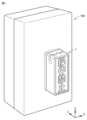
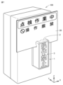
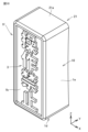
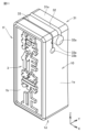
図1は、ブレーカ100に誤操作防止具1が取付けられている状態を示す図、図2は、実施の形態1の誤操作防止具1を説明するための斜視図、図3は、実施の形態1の誤操作防止具1を背面側から見た斜視図、図4は、図2のA-A線断面図、図5は、誤操作防止具1をブレーカ100に取付ける様子を示した図、図6は、誤操作防止具1をブレーカ100に対して逆向きに取付ける様子を示した図である。図1から図4に示すようにX軸、Y軸、Z軸を規定した場合、X軸方向が誤操作防止具1の左右方向、Y軸方向が誤操作防止具1の前後方向、Z軸方向が誤操作防止具1の上下方向とする。
[First embodiment]
Fig. 1 is a diagram showing a state in which the
図1に示すように、誤操作防止具1は、ブレーカ100に取付けることができる。ブレーカ100は、模式的に図示されている。誤操作防止具1は、樹脂で形成されている。なお、誤操作防止具1は、樹脂以外の金属等により形成されるようにしてもよい。図2から図4に示すように、誤操作防止具1は、6面を有する直方体形状に形成されている。
As shown in FIG. 1, the
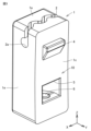
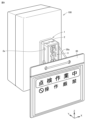
図2、図3に示すように、本体10は、第1面としてのXZ平面から構成される前面1bと、前面1bに対向する第2面としての後面1cとを有する。本体10は、Z軸方向に垂直な第3面としてのXY平面から構成される上面1aと、上面1aに対向する下面1dとを有する。本体10は、YZ平面から構成される右側面1eと左側面1fとを有する。
As shown in Figures 2 and 3, the
上面1には、波型の溝部2が形成されている。図4に示すように、溝部2の下方には、円柱状の穴部2aが形成されている。前面1bには、「操作禁止」の文字3が目立つ態様で表示されている。「操作禁止」の文字3は、立体的に形成されているが、平面的に表示されるものでもよい。文字3の内容は、適宜変更が可能であり、記号、図柄等であってもよいし、その組合せでもよい。
A
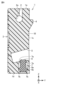
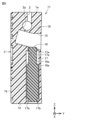
図3、図4に示すように、後面1cの上部位置には、後面1cから突出する凸部4が形成されている。後面1cの下部位置には、本体10の内部方向に向けて延びる凹部5が形成されている。凹部5の下方位置には、中空部7が形成されている。中空部7内には、凹部5へ突出可能な可動部材6が配置されている。
As shown in Figures 3 and 4, a
可動部材6は、円柱状の本体の下部位置にフランジ部6aが形成されている。可動部材6は、Z軸方向に移動する際に中空部7の内側に向けて延びる上面部7aまたは中空部7の内側に向けて延びる下面部7bとフランジ部6aとが接触することで可動範囲が制限される。なお、可動部材6は、本体が直方体形状等であってもよい。
The
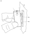
図5では、ブレーカ100に対して上下に移動可能な操作レバー100bがOFF位置である斜め下方向へ向いている様子が示されている。このとき、ブレーカ100に誤操作防止具1を取付ける際、凹部5に操作レバー100bを嵌合させる。誤操作防止具1がOFF位置の操作レバー100bに対して取付けられるとき、重力により可動部材6が中空部7内に移動しているため、凹部5に操作レバー100bが嵌合する。
Figure 5 shows the
凹部5を操作レバー100bに取り付ける際、誤操作防止具1は、ブレーカ100に形成された矩形状の切欠き部100aの上側の位置に凸部4が係合するように挿入されることにより、凸部4がブレーカ100に係合する。
When attaching the
図6では、ブレーカ100に対して操作レバー100bがON位置である斜め上方向へ向いている様子が示されている。このとき、凹部5に操作レバー100bを嵌合させようとしても凹部5へ向けて重力により鉛直方向に可動部材6が突出することによって、凹部5への操作レバーの進入が妨げられる。
Figure 6 shows the
図6のように、誤操作防止具1がON位置の操作レバー100bに対して取付けられるとき、図2に示す文字3は、上下が逆さまになるように表示されている。これにより、取付け位置が間違っていることを文字の向きで認識しやすくすることができる。
As shown in Figure 6, when the
このように、誤操作防止具1を操作レバー100bがON位置であるときに取付けようとしても凹部5へ操作レバーが進入することがない。これにより、操作レバー100bがON位置のままで点検をしてしまうような誤操作を確実に防止することができる。
In this way, even if you try to attach the
図7は、誤操作防止具1にカード20を取付けた状態を示す図である。図7に示すように、カード20には、注意書きが記載されており、点検作業中であること、操作が厳禁であること等が一目で分かるようになっている。カード20を誤操作防止具1の溝部2に差し込むことにより、カード20が溝部2に固定される。溝部2は、波形状に形成されているため、カード20との摩擦力により、風等によりカード20が誤操作防止具1から外れてしまうことを防止することができる。
Figure 7 is a diagram showing the state in which the
図8は、誤操作防止具1に下げ札30を取付けた状態を示す図である。図8に示すように、下げ札30には、注意書きが記載されており、点検作業中であること、操作が厳禁であること等が一目で分かるようになっている。下げ札30を誤操作防止具1の溝部2に差し込み、穴部2aに下げ札30を吊り下げるための紐部30aを引っ掛けることにより、下げ札30が溝部2から吊り下げられる。これにより、風等により下げ札30が誤操作防止具1から外れてしまうことを防止することができる。
Figure 8 is a diagram showing the state in which the
図7、図8に示すカード20と下げ札30とは、同時に使用してもよい。「操作禁止」の文字3が視認しやすいように、紐部30aを長くしてもよい。カード20と下げ札30と文字3とにより、効果的に誤操作を防止することができる。
The
[実施の形態2]
図9は、実施の形態2の誤操作防止具11を説明するための断面図である。実施の形態1の誤操作防止具1は、ブレーカ100に対して上下に移動可能な操作レバー100bがOFF位置である場合に取付けるものであった。それに対し、実施の形態2の誤操作防止具11は、ブレーカ100に対して上下に移動可能な操作レバー100bがON位置である場合に取付けるものである。
[Embodiment 2]
9 is a cross-sectional view for explaining the
図9に示すように、後面1cの上部位置には、本体10の内部方向に向けて延びる凹部15が形成されている。凹部15の下方位置には、本体10に中空部17が形成されている。中空部17内には、凹部15へ突出可能な可動部材16が配置されている。なお、実施の形態2の誤操作防止具11の後面1cには、後面1cから突出する凸部を形成しない方が好ましい。これは、過電流等によりブレーカ100が作動して電源が落ちたとき(トリップしたとき)に、凸部がトリップを妨げてしまう可能性を防ぐためである。しかしながら、操作レバー100bの可動範囲と重ならない位置であれば凸部を形成してもよい。
As shown in FIG. 9, a
可動部材16には、円柱状の本体の周囲にフランジ部16aが形成されている。可動部材16は、移動する際に中空部17の内側に向けて延びる上面部17aまたは中空部7の内側に向けて延びる下面部17bとフランジ部16aとが接触することで可動範囲が制限される。
The
ブレーカ100に対してON位置である斜め上方向へ向いた操作レバー100bに誤操作防止具11を取付ける際、凹部15に操作レバー100bを嵌合させる。誤操作防止具11がON位置の操作レバー100bに対して取付けられるとき、重力により可動部材16が凹部15へ突出しない位置に移動するため、凹部15に操作レバー100bが嵌合する。
When attaching the
ブレーカ100に対してOFF位置である斜め下方向へ向いた操作レバー100bに誤操作防止具11を取付ける。この場合、凹部15に操作レバー100bを嵌合させようとしても凹部15へ向けて重力により鉛直方向に可動部材16が突出することによって、凹部15への操作レバーの進入が妨げられる。
An erroneous
このように、誤操作防止具11を操作レバー100bがOFF位置であるときに取付けようとしても凹部15へ操作レバーが進入することがない。これにより、操作レバー100bをON位置で固定させておきたい場合にOFF位置で取付けてしまう誤操作を確実に防止することができる。
In this way, even if you try to attach the
[実施の形態3]
図10は、実施の形態3の誤操作防止具21を説明するための斜視図である。実施の形態3の誤操作防止具21は、実施の形態1の誤操作防止具1と上面の形状が異なっており、その他の形状は同じである。誤操作防止具21の上面21aは、誤操作防止具1の上面1aとは異なり、溝部2が形成されていない。
[Embodiment 3]
10 is a perspective view for explaining an operation
[実施の形態4]
図11は、実施の形態4の誤操作防止具31を説明するための斜視図である。実施の形態4の誤操作防止具31は、実施の形態1の誤操作防止具1と上面の形状が異なっており、その他の形状は同じである。誤操作防止具31の上面31aは、誤操作防止具1の上面1aとは異なり、2つの溝部32、33が形成されている。
[Fourth embodiment]
11 is a perspective view for explaining an operation
後側の溝部32は、穴部32aに図8で示した紐部30aを引っ掛けることにより、下げ札30が溝部32から吊り下げられるようになっている。前側の溝部33は、図7に示したカード20を差し込むことにより、カード20が溝部33に固定される。カード20は、右側面1eに示されるような段差部33aと接触することで抜けにくく、下方位置の穴部33bで進入するカード20が止まる。
The
[実施の形態5]
図12は、実施の形態5の誤操作防止具41を説明するための斜視図である。実施の形態5の誤操作防止具41は、実施の形態4の誤操作防止具31と後側の溝部の形状が異なっており、その他の形状は同じである。後側の溝部42は、穴部42aに図8で示した紐部30aを引っ掛けることにより、下げ札30が溝部42から吊り下げられるようになっている。後側の溝部42は、波型の形状であるため、図7に示したカード20を差し込み固定することも可能である。誤操作防止具41は、前側の溝部33および後側の溝部42の両方にカード20を差し込むような使用も可能である。
[Embodiment 5]
12 is a perspective view for explaining the
[まとめ]
本開示は、ブレーカ100の操作レバー100bの誤操作を防止するための誤操作防止具1である。誤操作防止具1は、前面1bおよび前面1bに対向する後面1cを有する本体10と、可動部材6と、を備える。本体10の後面1cには、操作レバー100bがOFF位置のときに操作レバー100bと嵌合する凹部5が形成されている。可動部材6は、凹部5の内部に突出可能に構成されている。誤操作防止具1がOFF位置の操作レバー100bに対して取付けられるとき、凹部5へ可動部材6が突出せず、凹部5に操作レバー100bが嵌合し、誤操作防止具1がOFF位置とは異なるON位置の操作レバー100bに対して取付けられるとき、凹部5へ可動部材6が突出することによって凹部5への操作レバー100bの進入が妨げられる。
[summary]
The present disclosure relates to a
このような構成を備えることによって、操作レバー100bの誤操作を確実に防止することができる。
By having such a configuration, it is possible to reliably prevent erroneous operation of the operating
好ましくは、可動部材6は、誤操作防止具1がON位置の操作レバー100bに対して取付けられるとき、重力により鉛直方向に突出する。
Preferably, the
このような構成を備えることによって、簡易な構造により操作レバー100bの誤操作を確実に防止することができる。
By providing such a configuration, it is possible to reliably prevent erroneous operation of the operating
好ましくは、本体10は、後面1cから突出する凸部4を有している。誤操作防止具1がOFF位置の操作レバー100bに対して取付けられるとき、凹部5に操作レバー100bが嵌合するとともに、凸部4がブレーカ100に係合する。
The
このような構成を備えることによって、凸部4と凹部5とにより強固に誤操作防止具1をブレーカ100に取付けることができる。
By having this configuration, the
好ましくは、鉛直方向に垂直な上面1aには、注意喚起のためのカード20または下げ札30を取付けるための溝部2が形成されている。
Preferably, a
このような構成を備えることによって、溝部2に注意喚起のためのカード20または下げ札30を取付けることができる。
By having such a configuration, a
好ましくは、溝部2は、波型に形成されている。
Preferably, the
このような構成を備えることによって、カード20または下げ札30が風等により落下することを防止できる。
This configuration can prevent the
好ましくは、第1面には、文字3が表示されている。文字3は、誤操作防止具1がON位置の操作レバー100bに対して取付けられるときに、文字3の上下が逆さまになるように表示されている。
Preferably, the first surface displays the
このような構成を備えることによって、取付け位置が間違っていることを文字の向きで認識しやすくすることができる。 By using this type of configuration, it becomes easier to recognize if the installation position is incorrect based on the orientation of the characters.
[変形例]
本体10の形状は、直方体状の形状以外の形状であってもよい。例えば、本体10を三角形あるいは台形とすることにより、使用者に上下の向きを容易に認識させることができる。
[Modification]
The shape of the
可動部材6は、重力により落下するものについて説明した。可動部材6は、使用者が手動で操作レバー100bが進入不可となる位置に移動するものであってもよい。
The
誤操作防止具1は、上下方向に操作レバー100bが動作するものに対して取付けるものについて説明した。誤操作防止具1は、左右方向に操作レバー100bが動作するものに対して取付けるものであってもよい。
The
今回開示された実施の形態はすべての点で例示であって制限的なものではないと考えられるべきである。本開示の範囲は上記した説明ではなくて請求の範囲によって示され、請求の範囲と均等の意味および範囲内でのすべての変更が含まれることが意図される。 The embodiments disclosed herein should be considered to be illustrative and not restrictive in all respects. The scope of the present disclosure is indicated by the claims, not the above description, and is intended to include all modifications within the meaning and scope of the claims.
1 誤操作防止具、1a 上面、1b 前面、1c 後面、1d 下面、1e 右側面、1f 左側面、2 溝部、2a 穴部、3 文字、4 凸部、5 凹部、6 可動部材、6a フランジ部、7 中空部、7a 上面部、7b 下面部、10 本体、20 カード、30 下げ札、30a 紐部、100 ブレーカ、100a 切欠き部、100b 操作レバー。 1 Misoperation prevention device, 1a Top surface, 1b Front surface, 1c Rear surface, 1d Bottom surface, 1e Right side surface, 1f Left side surface, 2 Groove portion, 2a Hole portion, 3 Letters, 4 Convex portion, 5 Concave portion, 6 Movable member, 6a Flange portion, 7 Hollow portion, 7a Top surface portion, 7b Bottom surface portion, 10 Main body, 20 Card, 30 Hanging tag, 30a String portion, 100 Breaker, 100a Notch portion, 100b Operating lever.
Claims (7)
前記誤操作防止具は、
第1面および前記第1面に対向する第2面を有する本体と、
可動部材と、を備え、
前記本体の前記第2面には、前記操作レバーが第1位置のときに前記操作レバーと嵌合する凹部が形成されており、
前記可動部材は、前記凹部の内部に突出可能に構成されており、
前記誤操作防止具が前記第1位置の前記操作レバーに対して取付けられるとき、前記凹部へ前記可動部材が突出せず、前記凹部に前記操作レバーが嵌合し、
前記誤操作防止具が前記第1位置とは異なる第2位置の前記操作レバーに対して取付けられるとき、前記凹部へ前記可動部材が突出することによって前記凹部への前記操作レバーの進入が妨げられる、誤操作防止具。 An erroneous operation prevention device for preventing erroneous operation of a breaker operating lever,
The erroneous operation prevention device is
a body having a first surface and a second surface opposite the first surface;
A movable member,
a recess into which the operating lever is fitted when the operating lever is in a first position is formed on the second surface of the main body,
The movable member is configured to be able to protrude into the recess,
When the erroneous operation prevention device is attached to the operating lever in the first position, the movable member does not protrude into the recess, and the operating lever fits into the recess,
When the misoperation prevention device is attached to the operating lever in a second position different from the first position, the movable member protrudes into the recess, thereby preventing the operating lever from entering the recess.
前記誤操作防止具が前記第1位置の前記操作レバーに対して取付けられるとき、前記凹部に前記操作レバーが嵌合するとともに、前記凸部が前記ブレーカに係合する、請求項1または請求項2に記載の誤操作防止具。 The main body has a protrusion protruding from the second surface,
3. The misoperation prevention device according to claim 1, wherein when the misoperation prevention device is attached to the operating lever in the first position, the operating lever fits into the recess and the protrusion engages with the breaker.
前記文字は、前記誤操作防止具が前記第2位置の前記操作レバーに対して取付けられるときに、前記文字の上下が逆さまになるように表示されている、請求項1から請求項5のいずれか1項に記載の誤操作防止具。 The first surface has characters displayed thereon,
The misoperation prevention device according to claim 1 , wherein the letters are displayed upside down when the misoperation prevention device is attached to the operating lever in the second position.
Priority Applications (1)
| Application Number | Priority Date | Filing Date | Title |
|---|---|---|---|
| JP2021102101A JP7658564B2 (en) | 2021-06-21 | 2021-06-21 | Misoperation prevention device |
Applications Claiming Priority (1)
| Application Number | Priority Date | Filing Date | Title |
|---|---|---|---|
| JP2021102101A JP7658564B2 (en) | 2021-06-21 | 2021-06-21 | Misoperation prevention device |
Publications (2)
| Publication Number | Publication Date |
|---|---|
| JP2023001411A JP2023001411A (en) | 2023-01-06 |
| JP7658564B2 true JP7658564B2 (en) | 2025-04-08 |
Family
ID=84688789
Family Applications (1)
| Application Number | Title | Priority Date | Filing Date |
|---|---|---|---|
| JP2021102101A Active JP7658564B2 (en) | 2021-06-21 | 2021-06-21 | Misoperation prevention device |
Country Status (1)
| Country | Link |
|---|---|
| JP (1) | JP7658564B2 (en) |
Citations (4)
| Publication number | Priority date | Publication date | Assignee | Title |
|---|---|---|---|---|
| KR200382953Y1 (en) | 2005-02-14 | 2005-04-27 | 포철기연주식회사 | Safety Cap for Switch of Control Panel |
| JP2008300237A (en) | 2007-05-31 | 2008-12-11 | Kawamura Electric Inc | Circuit breaker handle lock device and circuit breaker |
| US20100108477A1 (en) | 2007-04-20 | 2010-05-06 | Abb Ag | Installation switchgear having a lead-sealable actuation lever |
| CN204792656U (en) | 2015-07-01 | 2015-11-18 | 上海诺雅克电气有限公司 | Moulded case circuit breaker with handle locking device |
-
2021
- 2021-06-21 JP JP2021102101A patent/JP7658564B2/en active Active
Patent Citations (4)
| Publication number | Priority date | Publication date | Assignee | Title |
|---|---|---|---|---|
| KR200382953Y1 (en) | 2005-02-14 | 2005-04-27 | 포철기연주식회사 | Safety Cap for Switch of Control Panel |
| US20100108477A1 (en) | 2007-04-20 | 2010-05-06 | Abb Ag | Installation switchgear having a lead-sealable actuation lever |
| JP2008300237A (en) | 2007-05-31 | 2008-12-11 | Kawamura Electric Inc | Circuit breaker handle lock device and circuit breaker |
| CN204792656U (en) | 2015-07-01 | 2015-11-18 | 上海诺雅克电气有限公司 | Moulded case circuit breaker with handle locking device |
Also Published As
| Publication number | Publication date |
|---|---|
| JP2023001411A (en) | 2023-01-06 |
Similar Documents
| Publication | Publication Date | Title |
|---|---|---|
| KR100664364B1 (en) | Rotary Connector Device | |
| JP5440599B2 (en) | Electronic equipment | |
| JP2011010423A (en) | Electrical junction box | |
| JP6335687B2 (en) | Protective cover for electrical components | |
| JP4932756B2 (en) | A box containing parts inside | |
| JP7658564B2 (en) | Misoperation prevention device | |
| JP5065647B2 (en) | Storage structure of electrical junction box in storage box | |
| JP2012182965A (en) | Upper cover fitting detection structure of electric connection box | |
| CN101635207A (en) | trigger switch | |
| JP4075098B2 (en) | Control board storage box for gaming machines | |
| JP2014017167A (en) | Fixing structure of fuse holder and fuse cover | |
| KR200460895Y1 (en) | Inhibitor switch for a vehicle and assembly unit with the same | |
| JP2016015232A (en) | Protective cover for electric component | |
| JP6953995B2 (en) | Switch mounting structure | |
| JP5557706B2 (en) | Protective cover for electrical equipment | |
| JP5691952B2 (en) | Lever type connector | |
| JP5896223B2 (en) | Liquid level detector | |
| JP5264373B2 (en) | Fuse block | |
| JP4328298B2 (en) | fuse | |
| JP7475970B2 (en) | Mating detection structure | |
| CN216291721U (en) | Surrounding type EDR controller | |
| JP6253919B2 (en) | Fuse unit | |
| JP5603767B2 (en) | Measuring instrument | |
| JP6521364B2 (en) | Distribution board | |
| JP5157824B2 (en) | Electrical junction box and method of assembling the electrical junction box |
Legal Events
| Date | Code | Title | Description |
|---|---|---|---|
| A621 | Written request for application examination |
Free format text: JAPANESE INTERMEDIATE CODE: A621 Effective date: 20240529 |
|
| A977 | Report on retrieval |
Free format text: JAPANESE INTERMEDIATE CODE: A971007 Effective date: 20250207 |
|
| TRDD | Decision of grant or rejection written | ||
| A01 | Written decision to grant a patent or to grant a registration (utility model) |
Free format text: JAPANESE INTERMEDIATE CODE: A01 Effective date: 20250225 |
|
| A61 | First payment of annual fees (during grant procedure) |
Free format text: JAPANESE INTERMEDIATE CODE: A61 Effective date: 20250319 |
|
| R150 | Certificate of patent or registration of utility model |
Ref document number: 7658564 Country of ref document: JP Free format text: JAPANESE INTERMEDIATE CODE: R150 |