JP7657204B2 - Passive safety device, injection device including same, and method for manufacturing said injection device - Google Patents
Passive safety device, injection device including same, and method for manufacturing said injection device Download PDFInfo
- Publication number
- JP7657204B2 JP7657204B2 JP2022517419A JP2022517419A JP7657204B2 JP 7657204 B2 JP7657204 B2 JP 7657204B2 JP 2022517419 A JP2022517419 A JP 2022517419A JP 2022517419 A JP2022517419 A JP 2022517419A JP 7657204 B2 JP7657204 B2 JP 7657204B2
- Authority
- JP
- Japan
- Prior art keywords
- hub
- safety device
- sleeve
- injection
- distal
- Prior art date
- Legal status (The legal status is an assumption and is not a legal conclusion. Google has not performed a legal analysis and makes no representation as to the accuracy of the status listed.)
- Active
Links
Images


Classifications
-
- A—HUMAN NECESSITIES
- A61—MEDICAL OR VETERINARY SCIENCE; HYGIENE
- A61M—DEVICES FOR INTRODUCING MEDIA INTO, OR ONTO, THE BODY; DEVICES FOR TRANSDUCING BODY MEDIA OR FOR TAKING MEDIA FROM THE BODY; DEVICES FOR PRODUCING OR ENDING SLEEP OR STUPOR
- A61M5/00—Devices for bringing media into the body in a subcutaneous, intra-vascular or intramuscular way; Accessories therefor, e.g. filling or cleaning devices, arm-rests
- A61M5/178—Syringes
- A61M5/31—Details
- A61M5/32—Needles; Details of needles pertaining to their connection with syringe or hub; Accessories for bringing the needle into, or holding the needle on, the body; Devices for protection of needles
- A61M5/3205—Apparatus for removing or disposing of used needles or syringes, e.g. containers; Means for protection against accidental injuries from used needles
- A61M5/321—Means for protection against accidental injuries by used needles
- A61M5/3213—Caps placed axially onto the needle, e.g. equipped with finger protection guards
-
- A—HUMAN NECESSITIES
- A61—MEDICAL OR VETERINARY SCIENCE; HYGIENE
- A61M—DEVICES FOR INTRODUCING MEDIA INTO, OR ONTO, THE BODY; DEVICES FOR TRANSDUCING BODY MEDIA OR FOR TAKING MEDIA FROM THE BODY; DEVICES FOR PRODUCING OR ENDING SLEEP OR STUPOR
- A61M5/00—Devices for bringing media into the body in a subcutaneous, intra-vascular or intramuscular way; Accessories therefor, e.g. filling or cleaning devices, arm-rests
- A61M5/178—Syringes
- A61M5/31—Details
- A61M5/32—Needles; Details of needles pertaining to their connection with syringe or hub; Accessories for bringing the needle into, or holding the needle on, the body; Devices for protection of needles
- A61M5/3202—Devices for protection of the needle before use, e.g. caps
-
- A—HUMAN NECESSITIES
- A61—MEDICAL OR VETERINARY SCIENCE; HYGIENE
- A61M—DEVICES FOR INTRODUCING MEDIA INTO, OR ONTO, THE BODY; DEVICES FOR TRANSDUCING BODY MEDIA OR FOR TAKING MEDIA FROM THE BODY; DEVICES FOR PRODUCING OR ENDING SLEEP OR STUPOR
- A61M5/00—Devices for bringing media into the body in a subcutaneous, intra-vascular or intramuscular way; Accessories therefor, e.g. filling or cleaning devices, arm-rests
- A61M5/178—Syringes
- A61M5/31—Details
- A61M5/32—Needles; Details of needles pertaining to their connection with syringe or hub; Accessories for bringing the needle into, or holding the needle on, the body; Devices for protection of needles
- A61M5/3205—Apparatus for removing or disposing of used needles or syringes, e.g. containers; Means for protection against accidental injuries from used needles
- A61M5/321—Means for protection against accidental injuries by used needles
- A61M5/3243—Means for protection against accidental injuries by used needles being axially-extensible, e.g. protective sleeves coaxially slidable on the syringe barrel
- A61M5/3245—Constructional features thereof, e.g. to improve manipulation or functioning
-
- A—HUMAN NECESSITIES
- A61—MEDICAL OR VETERINARY SCIENCE; HYGIENE
- A61M—DEVICES FOR INTRODUCING MEDIA INTO, OR ONTO, THE BODY; DEVICES FOR TRANSDUCING BODY MEDIA OR FOR TAKING MEDIA FROM THE BODY; DEVICES FOR PRODUCING OR ENDING SLEEP OR STUPOR
- A61M5/00—Devices for bringing media into the body in a subcutaneous, intra-vascular or intramuscular way; Accessories therefor, e.g. filling or cleaning devices, arm-rests
- A61M5/178—Syringes
- A61M5/31—Details
- A61M5/32—Needles; Details of needles pertaining to their connection with syringe or hub; Accessories for bringing the needle into, or holding the needle on, the body; Devices for protection of needles
- A61M5/3205—Apparatus for removing or disposing of used needles or syringes, e.g. containers; Means for protection against accidental injuries from used needles
- A61M5/321—Means for protection against accidental injuries by used needles
- A61M5/3243—Means for protection against accidental injuries by used needles being axially-extensible, e.g. protective sleeves coaxially slidable on the syringe barrel
- A61M5/326—Fully automatic sleeve extension, i.e. in which triggering of the sleeve does not require a deliberate action by the user
-
- A—HUMAN NECESSITIES
- A61—MEDICAL OR VETERINARY SCIENCE; HYGIENE
- A61M—DEVICES FOR INTRODUCING MEDIA INTO, OR ONTO, THE BODY; DEVICES FOR TRANSDUCING BODY MEDIA OR FOR TAKING MEDIA FROM THE BODY; DEVICES FOR PRODUCING OR ENDING SLEEP OR STUPOR
- A61M5/00—Devices for bringing media into the body in a subcutaneous, intra-vascular or intramuscular way; Accessories therefor, e.g. filling or cleaning devices, arm-rests
- A61M5/178—Syringes
- A61M5/31—Details
- A61M5/32—Needles; Details of needles pertaining to their connection with syringe or hub; Accessories for bringing the needle into, or holding the needle on, the body; Devices for protection of needles
- A61M5/3205—Apparatus for removing or disposing of used needles or syringes, e.g. containers; Means for protection against accidental injuries from used needles
- A61M5/321—Means for protection against accidental injuries by used needles
- A61M5/3243—Means for protection against accidental injuries by used needles being axially-extensible, e.g. protective sleeves coaxially slidable on the syringe barrel
- A61M5/3271—Means for protection against accidental injuries by used needles being axially-extensible, e.g. protective sleeves coaxially slidable on the syringe barrel with guiding tracks for controlled sliding of needle protective sleeve from needle exposing to needle covering position
-
- A—HUMAN NECESSITIES
- A61—MEDICAL OR VETERINARY SCIENCE; HYGIENE
- A61M—DEVICES FOR INTRODUCING MEDIA INTO, OR ONTO, THE BODY; DEVICES FOR TRANSDUCING BODY MEDIA OR FOR TAKING MEDIA FROM THE BODY; DEVICES FOR PRODUCING OR ENDING SLEEP OR STUPOR
- A61M5/00—Devices for bringing media into the body in a subcutaneous, intra-vascular or intramuscular way; Accessories therefor, e.g. filling or cleaning devices, arm-rests
- A61M5/178—Syringes
- A61M5/31—Details
- A61M5/32—Needles; Details of needles pertaining to their connection with syringe or hub; Accessories for bringing the needle into, or holding the needle on, the body; Devices for protection of needles
- A61M5/3293—Needles; Details of needles pertaining to their connection with syringe or hub; Accessories for bringing the needle into, or holding the needle on, the body; Devices for protection of needles characterised by features of the needle hub
-
- A—HUMAN NECESSITIES
- A61—MEDICAL OR VETERINARY SCIENCE; HYGIENE
- A61M—DEVICES FOR INTRODUCING MEDIA INTO, OR ONTO, THE BODY; DEVICES FOR TRANSDUCING BODY MEDIA OR FOR TAKING MEDIA FROM THE BODY; DEVICES FOR PRODUCING OR ENDING SLEEP OR STUPOR
- A61M5/00—Devices for bringing media into the body in a subcutaneous, intra-vascular or intramuscular way; Accessories therefor, e.g. filling or cleaning devices, arm-rests
- A61M5/178—Syringes
- A61M5/31—Details
- A61M5/32—Needles; Details of needles pertaining to their connection with syringe or hub; Accessories for bringing the needle into, or holding the needle on, the body; Devices for protection of needles
- A61M5/34—Constructions for connecting the needle, e.g. to syringe nozzle or needle hub
-
- A—HUMAN NECESSITIES
- A61—MEDICAL OR VETERINARY SCIENCE; HYGIENE
- A61M—DEVICES FOR INTRODUCING MEDIA INTO, OR ONTO, THE BODY; DEVICES FOR TRANSDUCING BODY MEDIA OR FOR TAKING MEDIA FROM THE BODY; DEVICES FOR PRODUCING OR ENDING SLEEP OR STUPOR
- A61M5/00—Devices for bringing media into the body in a subcutaneous, intra-vascular or intramuscular way; Accessories therefor, e.g. filling or cleaning devices, arm-rests
- A61M5/178—Syringes
- A61M5/31—Details
- A61M5/32—Needles; Details of needles pertaining to their connection with syringe or hub; Accessories for bringing the needle into, or holding the needle on, the body; Devices for protection of needles
- A61M5/3205—Apparatus for removing or disposing of used needles or syringes, e.g. containers; Means for protection against accidental injuries from used needles
- A61M5/321—Means for protection against accidental injuries by used needles
- A61M5/3243—Means for protection against accidental injuries by used needles being axially-extensible, e.g. protective sleeves coaxially slidable on the syringe barrel
- A61M5/3245—Constructional features thereof, e.g. to improve manipulation or functioning
- A61M2005/3247—Means to impede repositioning of protection sleeve from needle covering to needle uncovering position
-
- A—HUMAN NECESSITIES
- A61—MEDICAL OR VETERINARY SCIENCE; HYGIENE
- A61M—DEVICES FOR INTRODUCING MEDIA INTO, OR ONTO, THE BODY; DEVICES FOR TRANSDUCING BODY MEDIA OR FOR TAKING MEDIA FROM THE BODY; DEVICES FOR PRODUCING OR ENDING SLEEP OR STUPOR
- A61M5/00—Devices for bringing media into the body in a subcutaneous, intra-vascular or intramuscular way; Accessories therefor, e.g. filling or cleaning devices, arm-rests
- A61M5/178—Syringes
- A61M5/31—Details
- A61M5/32—Needles; Details of needles pertaining to their connection with syringe or hub; Accessories for bringing the needle into, or holding the needle on, the body; Devices for protection of needles
- A61M5/3205—Apparatus for removing or disposing of used needles or syringes, e.g. containers; Means for protection against accidental injuries from used needles
- A61M5/321—Means for protection against accidental injuries by used needles
- A61M5/3243—Means for protection against accidental injuries by used needles being axially-extensible, e.g. protective sleeves coaxially slidable on the syringe barrel
- A61M5/326—Fully automatic sleeve extension, i.e. in which triggering of the sleeve does not require a deliberate action by the user
- A61M2005/3267—Biased sleeves where the needle is uncovered by insertion of the needle into a patient's body
-
- A—HUMAN NECESSITIES
- A61—MEDICAL OR VETERINARY SCIENCE; HYGIENE
- A61M—DEVICES FOR INTRODUCING MEDIA INTO, OR ONTO, THE BODY; DEVICES FOR TRANSDUCING BODY MEDIA OR FOR TAKING MEDIA FROM THE BODY; DEVICES FOR PRODUCING OR ENDING SLEEP OR STUPOR
- A61M2207/00—Methods of manufacture, assembly or production
Landscapes
- Health & Medical Sciences (AREA)
- Engineering & Computer Science (AREA)
- Hematology (AREA)
- Anesthesiology (AREA)
- Biomedical Technology (AREA)
- Heart & Thoracic Surgery (AREA)
- Vascular Medicine (AREA)
- Life Sciences & Earth Sciences (AREA)
- Animal Behavior & Ethology (AREA)
- General Health & Medical Sciences (AREA)
- Public Health (AREA)
- Veterinary Medicine (AREA)
- Environmental & Geological Engineering (AREA)
- Infusion, Injection, And Reservoir Apparatuses (AREA)
Description
本発明は、受動針安全装置、この受動針安全装置を備える予備充填シリンジなどの注射装置、及び前記注射装置を製造するための方法に関する。 The present invention relates to a passive needle safety device, an injection device such as a pre-filled syringe equipped with the passive needle safety device, and a method for manufacturing the injection device.
本出願において、構成部分または装置の遠位端は、使用者の手から最も遠い端を意味すると理解され、近位端は、使用者の手に最も近い端を意味すると理解されるべきである。同様に、本出願において、「遠位方向」は、本発明の受動安全装置または注射装置に関して、注射方向を意味するものとして理解されるべきであり、「近位方向」は、前記注射方向と反対方向、すなわち、ユーザの手に向かう方向を意味するものとして理解されるべきである。 In this application, the distal end of a component or device shall be understood to mean the end furthest from the user's hand, and the proximal end shall be understood to mean the end closest to the user's hand. Similarly, in this application, the "distal direction" shall be understood to mean, in relation to the passive safety device or injection device of the present invention, the injection direction, and the "proximal direction" shall be understood to mean the direction opposite to said injection direction, i.e., towards the user's hand.
充填可能な注射器または充填済み注射器などの注射装置は、通常、医療製品の容器を形成する中空の本体またはバレルを備える。容器は、医薬品が容器から排出される軸方向の通路を画定する長手方向の先端の形態の遠位端を有する。遠位端には、患者の皮膚に挿入され、注射される製品が注射部位に通過するように設計された針が装備されている。 An injection device, such as a fillable or prefilled syringe, typically comprises a hollow body or barrel forming a container for a medical product. The container has a distal end in the form of a longitudinal tip that defines an axial passage through which the medicinal product is expelled from the container. The distal end is equipped with a needle designed to be inserted into the patient's skin and pass the product to be injected to the injection site.
針刺し損傷のリスクを最小限に抑えるために、注射装置に注射後に針を保護する安全装置を提供することが知られている。この安全装置は、通常、注射装置の遠位端に対してスライドし、注射部位からの針の引き抜き後に針を覆うスリーブを備える。 To minimise the risk of needlestick injuries, it is known to provide injection devices with a safety device which protects the needle after injection. This safety device typically comprises a sleeve which slides against the distal end of the injection device and covers the needle after withdrawal of the needle from the injection site.
安全装置は、能動的であっても受動的であってもよい。能動安全装置は、ユーザによって作動させる必要があり、すなわち、注射が完了すると針の保護をトリガーするために、ユーザが特定のアクションを実行する必要がある。対照的に、受動安全装置は、注射が完了すると針が確実に保護されるように、ユーザが何らかのアクションを実行する必要はない。 Safeties can be either active or passive. Active safeties must be activated by the user, i.e., the user must take a specific action to trigger needle protection once the injection is complete. In contrast, passive safeties do not require the user to take any action to ensure that the needle is protected once the injection is complete.
特許文献1は、そのような受動安全装置を開示している。この安全装置は、針保護位置と非保護位置との間で軸方向に摺動可能なスリーブを備える。このスリーブの近位部分は、非保護位置に到達するように半径方向外向きに変形するように構成される。この変形は、注射部位から針が取り外されると、前記スリーブの近位部分がスリーブ全体をその初期保護位置に戻すばねとして作用するようにエネルギーを蓄積することを可能にする。しかしながら、効果的なばね効果を達成するためには、スリーブの近位部分を最大限に変形させる必要がある。これには、針が注射部位にかなり長い距離に挿入されることが含まれる。これは、ユーザにとってストレスであったり有害であったりする可能性がある。さらに、上述のように、スリーブの近位部分は、半径方向外向きに延在するように構成される。この外向きの変形は、安全装置を半径方向にかなり煩雑にする。さらに、スリーブの変形は可視であり、ユーザを心配させる可能性がある。 Patent document 1 discloses such a passive safety device. The safety device comprises a sleeve that is axially slidable between a needle-protecting position and an unprotecting position. The proximal portion of the sleeve is configured to deform radially outward to reach the unprotected position. This deformation allows the proximal portion of the sleeve to store energy so that, upon removal of the needle from the injection site, the proximal portion of the sleeve acts as a spring to return the entire sleeve to its initial protective position. However, to achieve an effective spring effect, the proximal portion of the sleeve needs to be deformed to the maximum extent. This involves inserting the needle into the injection site a significant distance. This can be stressful or harmful to the user. Furthermore, as mentioned above, the proximal portion of the sleeve is configured to extend radially outward. This outward deformation makes the safety device quite cumbersome in the radial direction. Moreover, the deformation of the sleeve is visible and can be worrying to the user.
特許文献2および特許文献3は、ニードルガードを開示している。
したがって、よりコンパクトであり、受動安全装置を製造することが容易である必要があり、前記安全装置は、注射が完了すると、針の信頼できる保護を可能にする。 There is therefore a need for a more compact and easy to manufacture passive safety device, which allows reliable protection of the needle once the injection is completed.
本発明の態様は、受動安全装置であって:
前記注射装置の遠位先端に固定されるように構成された近位端を有するスリーブと、
使用前位置と、前記ハブが前記使用前位置に対して近位に位置する注射位置と、前記ハブが前記注射位置に対して遠位に位置する安全位置との間で前記スリーブに摺動可能に取り付けられたハブと、
前記安全位置に向かって前記ハブを遠位に押し出すように構成された付勢要素と、
前記使用前位置と前記注射位置との間の前記スリーブに対して前記ハブと共にスライドするように構成されたプロテクタと、を備える受動安全装置であり、前記安全装置は、
前記ハブが前記注射位置にあるときに前記プロテクタの遠位移動をブロックし、前記プロテクタが前記ハブと共に遠位方向にスライドするのを防止するように構成された第1のブロック手段と、
ハブが安全位置にあるときにハブの近位移動をブロックするように構成される第2のブロック手段と、をさらに備える。
An aspect of the present invention is a passive safety device comprising:
a sleeve having a proximal end configured to be secured to a distal tip of the injection device;
a hub slidably mounted on the sleeve between a pre-use position, an injection position in which the hub is proximal to the pre-use position, and a safety position in which the hub is distal to the injection position;
a biasing element configured to urge the hub distally toward the safe position;
a protector configured to slide with the hub against the sleeve between the pre-use position and the injection position, the safety device comprising:
a first blocking means configured to block distal movement of the protector when the hub is in the injection position and to prevent the protector from sliding distally with the hub;
and second blocking means configured to block proximal movement of the hub when the hub is in the safe position.
したがって、本発明の針安全装置は、コンパクトであり、製造が容易である一方で、注射後の針の信頼できる保護を可能にする。 The needle safety device of the present invention is therefore compact and easy to manufacture whilst allowing reliable protection of the needle after injection.
本出願において、「受動安全装置」とは、注射部位から針を除去した後に針を保護するように、ユーザが注射後にいかなる行動も取る必要のない針安全装置を意味する。 For the purposes of this application, "passive safety device" means a needle safety device that does not require the user to take any action after an injection to protect the needle after it is removed from the injection site.
一実施形態では、第1のブロック手段は、ハブが注射位置に到達したときにプロテクタをスリーブでスナップさせるように構成された第1のスナップ手段である。 In one embodiment, the first blocking means is a first snap means configured to snap the protector with the sleeve when the hub reaches the injection position.
これにより、コンパクトで製造しやすい安全装置を提供する。 This provides a safety device that is compact and easy to manufacture.
一実施形態では、第1のスナップ手段は、プロテクタ上に設けられる。 In one embodiment, the first snap means is provided on the protector.
この機能により、安全装置のコンパクト性が向上する。 This feature improves the compactness of the safety device.
一実施形態では、第1のスナップ手段は、ハブが使用前位置から注射位置に向かって移動するときにスリーブの長手方向スロットに摺動可能に係合される少なくとも1つの第1の弾性脚を含み、前記少なくとも1つの第1の弾性脚は、スリーブのブロック部材の遠位側に対して半径方向に変形し、ハブが注射位置にあるときに前記ブロック部材の近位側に隣接するように構成される。 In one embodiment, the first snap means includes at least one first resilient leg slidably engaged in a longitudinal slot of the sleeve when the hub moves from the pre-use position towards the injection position, the at least one first resilient leg being configured to deform radially relative to a distal side of the blocking member of the sleeve and to abut a proximal side of the blocking member when the hub is in the injection position.
これは、ハブが注射位置にあるときにプロテクタの遠位移動をブロックするために、コンパクトで製造が容易なソリューションを提供する。 This provides a compact, easy to manufacture solution for blocking distal movement of the protector when the hub is in the injection position.
一実施形態では、第2のブロック手段は、ハブが前記安全位置に到達したときにハブをスナップさせるように構成された第2のスナップ手段である。 In one embodiment, the second blocking means is a second snap means configured to snap the hub when the hub reaches the safe position.
これにより、コンパクトで製造しやすい安全装置を提供する。 This provides a safety device that is compact and easy to manufacture.
一実施形態では、第2のスナップ手段がプロテクタ上に設けられている。 In one embodiment, a second snap means is provided on the protector.
この機能により、安全装置のコンパクト性が向上する。 This feature improves the compactness of the safety device.
一実施形態では、第2のスナップ手段は、ハブが注射位置から安全位置に向かって移動するときにハブの近位スロットに摺動可能に係合される少なくとも1つの第2の弾性脚を備え、前記少なくとも1つの弾性脚は、ハブのブロック部材の遠位側に対して半径方向に変形し、ハブが安全位置にあるときに前記ブロック部材の近位側に隣接するように構成される。 In one embodiment, the second snap means comprises at least one second resilient leg slidably engaged in a proximal slot of the hub when the hub moves from the injection position towards the safety position, the at least one resilient leg being configured to deform radially relative to a distal side of the blocking member of the hub and to abut a proximal side of the blocking member when the hub is in the safety position.
これは、ハブが安全位置に到達すると、ハブの近位移動をブロックするために、コンパクトで簡単に製造できるソリューションを提供する。 This provides a compact and easy to manufacture solution to block proximal movement of the hub once it reaches a safe position.
一実施形態では、ハブは、ハブの近位スロットの近位端を画定する近位押出面を含み、前記近位押出面は、ハブが使用前位置から注射位置に移動するときに、前記プロテクタをハブと一緒にスライドさせるために、少なくとも1つの第2の弾性脚に当接するように構成される。 In one embodiment, the hub includes a proximal extrusion surface that defines a proximal end of a proximal slot in the hub, the proximal extrusion surface configured to abut at least one second resilient leg to cause the protector to slide with the hub as the hub moves from the pre-use position to the injection position.
これにより、安全装置のコンパクト性が向上する。 This makes the safety device more compact.
一実施形態では、第2のスナップ手段は、ハブが注射位置から安全位置に向かって移動するときにハブの近位スロットに摺動可能に係合される少なくとも1つの第2の弾性脚を備え、前記少なくとも1つの弾性脚は、ハブのブロック部材の遠位側に対して半径方向に変形し、ハブが安全位置にあるときに前記ブロック部材の近位側に隣接するように構成される。 In one embodiment, the second snap means comprises at least one second resilient leg slidably engaged in a proximal slot of the hub when the hub moves from the injection position towards the safety position, the at least one resilient leg being configured to deform radially relative to a distal side of the blocking member of the hub and to abut a proximal side of the blocking member when the hub is in the safety position.
スリーブの長手方向脚は、ハブをこの使用前位置に保持し、付勢要素の作用に対して保持するように、ハブの使用前位置の保持部材の遠位側に当接するように構成された半径方向突起を備え得る。 The longitudinal legs of the sleeve may include radial projections configured to abut the distal side of the retaining member in the pre-use position of the hub to retain the hub in this pre-use position and against the action of the biasing element.
一実施形態では、ハブは、保持フックなどの少なくとも1つの内側保持要素を含み、付勢要素は、ハブに遠位力を及ぼすために、前記内側保持要素に当接する遠位端を含み、スリーブは、ハブが注射位置に向かって移動するときに、前記少なくとも1つの保持要素が前記長手方向スロットに貫通及びスライドすることを可能にするために、開いた遠位端を備えた長手方向スロットを有する。 In one embodiment, the hub includes at least one internal retaining element, such as a retaining hook, the biasing element includes a distal end that abuts the internal retaining element to exert a distal force on the hub, and the sleeve has a longitudinal slot with an open distal end to allow the at least one retaining element to penetrate and slide into the longitudinal slot as the hub moves toward the injection position.
これにより、安全装置のコンパクト性が向上する。 This makes the safety device more compact.
一実施形態では、プロテクタは、支持リングを含み、第1のブロック手段は、前記支持リングから近位に延びる少なくとも1つの第1の弾性脚を含み、第2のブロック手段は、前記支持リングから遠位に延びる少なくとも1つの第2の弾性脚を含む。 In one embodiment, the protector includes a support ring, the first blocking means includes at least one first resilient leg extending proximally from said support ring, and the second blocking means includes at least one second resilient leg extending distally from said support ring.
その結果、第1の弾性脚および第2の弾性脚は、支持リングの反対側に位置する。これにより、安全装置のコンパクト性が向上する。 As a result, the first elastic leg and the second elastic leg are located on opposite sides of the support ring. This improves the compactness of the safety device.
一実施形態では、少なくとも1つの第1の弾性脚および少なくとも1つの第2の弾性脚は、支持リングの円周方向にオフセットされる。 In one embodiment, the at least one first resilient leg and the at least one second resilient leg are offset circumferentially about the support ring.
その結果、第1の弾性脚及び第2の弾性脚は、支持リングに沿って交互になる。これにより、安全装置のコンパクト性が向上する。 As a result, the first elastic leg and the second elastic leg alternate along the support ring. This improves the compactness of the safety device.
一実施形態では、プロテクタは、ハブ上で互いに直接組み立てられるように構成された2つの部品で構成される。 In one embodiment, the protector is made up of two pieces configured to be assembled directly together on the hub.
これにより、安全装置の製造が容易になる。プロテクタを形成する2つの部品のそれぞれは、前記支持リングの半円形の半分に対応し得る。2つの部品は同一であってもよい。 This makes it easier to manufacture the safety device. Each of the two parts forming the protector may correspond to one half of the semicircle of the support ring. The two parts may be identical.
本発明の別の態様は、上記の受動安全装置を備える注射装置である。 Another aspect of the present invention is an injection device equipped with the above-mentioned passive safety device.
本発明の別の態様は、上記注射装置を製造するための方法であって:
(i) 前記受動針安全装置の前記針を前記注射装置の遠位先端に固定するステップと、
(ii) 前記受動針安全装置の前記付勢要素を前記スリーブに配置するステップと、
(iii) 前記受動針安全装置の前記ハブを前記付勢要素の前記作用に対して前記スリーブ上に配置するステップと、
(iv) 前記受動針安全装置の前記プロテクタを前記ハブ及び前記スリーブ上に配置するステップと、を含む、方法である。
Another aspect of the invention is a method for producing an injection device as described above, comprising the steps of:
(i) securing the needle of the passive needle safety device to a distal tip of the injection device;
(ii) disposing the biasing element of the passive needle safety device in the sleeve;
(iii) positioning the hub of the passive needle safety device onto the sleeve against the action of the biasing element;
(iv) disposing the protector of the passive needle safety device over the hub and the sleeve.
本発明およびそれから生じる利点は、以下の添付の図面を参照して以下に示す詳細な説明から明らかになる:
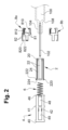
図1を参照すると、本発明の一実施形態による受動安全装置1が示される。受動安全装置1は、針刺しの傷害を防止するために、注射装置100の針102を注射の終わりに覆うように構成される。
Referring to FIG. 1, a passive safety device 1 according to one embodiment of the present invention is shown. The passive safety device 1 is configured to cover the
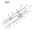
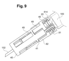
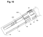
安全装置1は、安全装置1が注射を実行する準備ができている使用前位置(図1、8、11 )、安全装置1が針102を注射部位に入ることを可能にするために針を露出させる注射位置(図9、12)、及び安全装置1が針102を覆い、針刺しの傷害を防止する安全位置(図10、13)の3つの連続した位置を採用してもよい。使用前の位置と安全位置は同一であっても異なっていてもよい。
The safety device 1 may adopt three successive positions: a pre-use position in which the safety device 1 is ready to perform an injection (Figs. 1, 8, 11), an injection position in which the safety device 1 exposes the
図1、2、3A及び3Bを参照すると、安全装置1は、注射装置100の遠位先端104に固定的に取り付けられるように構成されたスリーブ2、スリーブ2に摺動可能に取り付けられるハブ4、ハブ4を遠位方向に押し付ける付勢要素6、及びスリーブ2に摺動可能に取り付けられるプロテクタ8を含む。安全装置1は、ハブ4が注射位置に到達したときにプロテクタ8をブロックするように構成された第1のブロック手段と、ハブ4が安全位置にあるときにハブ4をブロックするように構成された第2のブロック手段とをさらに備え、以下でさらに詳細に説明する。
With reference to Figures 1, 2, 3A and 3B, the safety device 1 includes a
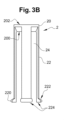
管状スリーブ2は、長手方向軸Aに沿って長手方向に延びる。スリーブ2は、遠位先端104および針102の近位部分を取り囲むように構成される。スリーブ2は、近位端および反対側の遠位端を含む。近位端は、例えば、接着、ねじ込み、連動、圧入などによって、注射装置100の遠位先端104に固定されるように構成される。スリーブ2は、スリーブ2の近位端に位置してもよく、固定リング20の形態であってもよいブロック部材を備える。図3Aに見られるように、固定リング20は、遠位先端104を収容する中心貫通開口部204を画定する。固定リング20はまた、近位側及び反対側の遠位側を有する。遠位側は、傾斜した表面200を画定し得る。近位側は、当接面202を画定し得る。
The
スリーブ2は、長手方向スロット24によって互いに分離された1つまたはいくつかの長手方向脚22をさらに含んでもよい。長手方向脚22及び長手方向スロット24は、長手方向軸Aに平行に延在してもよい。長手方向スロット24は、それらの遠位端で開き、それらの近位端で固定リング20によって閉じてもよい。長手方向脚22は、スリーブ2の遠位端を形成し得る自由な遠位端と、固定リング20に接続され得る反対側の近位端とを有し得る。したがって、長手方向脚22は、前記固定リング20から遠位に延びる。長手方向脚22は、固定リング20に沿って規則的に分布し得る。スリーブ2の長手方向脚22は、半径方向内向きに偏向するように構成され得る。長手方向脚22は、外向きに延びる半径方向突起220などの半径方向突起220を含んでもよく、その機能は以下に現れるであろう。この半径方向突起220は、長手方向脚22の自由遠位端に位置してもよい。半径方向突起220は、可能性のある傾斜、偏向及び/または保持面222を画定し得る近位側と、ブロック面224を画定し得る遠位側とを有する。
The
図1、2及び4を参照すると、ハブ4は、長手方向軸Aに沿って長手方向に延びる。ハブ4は、スリーブ2を取り囲む。より具体的には、ハブ4は、ハブ4の遠位端が、針102を覆うように針102の先端を超えて遠位に配置されるように構成されてもよい、使用前位置(図1、図8、図11)と、ハブ4が針102を露出させるように使用前位置に対して近位に格納される注射位置(図9、図12)と、及び、針刺された傷害を回避するために、ハブ4が針102を覆うように、ハブ4の遠位端が針102の先端を超えて遠位に延びるように構成されている安全位置(図10、図13)との間の軸Aに沿ってスリーブ2に摺動可能に取り付けられる。
1, 2 and 4, the
管状ハブ4は、遠位端及び反対側の近位端を有する。遠位端は、注射を実行するために、針102が前記開口部40を通って延びるように構成された中央開口部400を画定する。ハブ4の遠位端は、典型的には患者の皮膚などの注射部位に接触し、針102が注射部位に入るときにハブ4を注射位置に近位に押し付けるように構成された当接面402をさらに備える。当接面402は、開口部400を取り囲んでもよい。図4に示されるように、ハブ4の近位端は、スリーブ2を受容する開口部44を画定する。
The
ハブ4は、ハブ4の近位端に位置し得るブロック部材を備える。ブロック部材は、ブロックリング46の形態であってもよい。前記ブロックリング46は、近位側及び反対側の遠位側を有する。図4に最もよく示されるように、近位側は、ブロック面460を画定する。遠位側は、傾斜した偏向面462を画定し得る。
The
ハブ4は、長手方向軸Aに平行に延在する1つまたは複数の近位スロット48を備える。近位スロット48は、上方に延在してもよく、スリーブ2の長手方向脚22と整列してもよい。近位スロット48は、ブロックリング46によって近位端で閉じられる。近位スロット48はまた、押出面410によってその遠位端で閉じられてもよく、前記押出面410は、ハブ4が注射位置に向かって移動するときにプロテクタ8を近位方向に押し、プロテクタ8がハブ4と共に注射位置に向かってスライドするように構成される。
The
ハブ4は、長手方向軸Aに平行に延びる1つまたは複数の遠位スロット49を備えてもよい。遠位スロット49は、近位スロット48と整列し、近位スロット48に対して遠位に位置する。遠位スロット49は、ハブ4の遠位端を形成し得、したがって中央開口部400及び当接面402を区切る、遠位リング40によって遠位端で閉じられ得る。遠位スロット49は、遠位保持面412によって、その近位端で閉じられてもよい。遠位保持面412は、注射の前に、付勢要素6によって及ぼされる力に対して使用前の位置にハブ4を維持するように、長手方向脚22の半径方向突起220に当接するように構成され得る。近位スロット48および/または遠位スロット49は、ハブ4の円周方向に沿って規則的に分布し得る。
The
スリーブ2の半径方向突起220及びハブ4の遠位スロット49はまた、スリーブ2に対するハブ4の並進を誘導するように誘導手段として機能してもよい。
The
ハブ4は、近位スロット48の遠位端および/または遠位スロット49の近位端に位置し得る保持部材を含んでもよい。保持部材は、近位スロット48を隣接する遠位スロット49から分離し得る中間リング41の形態であってもよい。中間リング41は、押出面410を画定し得る近位側を備える。中間リング41は、遠位保持面412を画定し得る遠位側を備える。前記遠位保持面412は、前記遠位保持面412が半径方向突起220に当接するときに、スリーブ2の長手方向脚22の内向きの変形を有利にするように傾斜されてもよい。したがって、半径方向突起220は、ハブ4が安全位置に向かって移動するときに、遠位スロット49を係合解除し、近位スロット48と係合し得る。
The
ハブ4は、付勢要素6の遠位端に支持を提供するように、ハブ4の内側側壁から延在し得るフック42などの1つまたは複数の保持要素を含んでもよい。これらの保持要素は、ハブ4が注射位置に向かって移動するときに、スリーブ2の長手方向スロット24に沿って入り、スライドするように構成され、それにより、付勢要素6はエネルギーを蓄積する。
The
付勢要素6は、例えば、内向きに突出するフック42によって遠位端がハブ4に接続され、近位端がスリーブ2と遠位先端104との間に固定されるばねであってもよい。
The biasing
図1、2及び5を参照すると、プロテクタ8は、スリーブ2を取り囲み、ハブ4に対して近位に位置する。プロテクタ8は、ハブ4が使用前位置から注射位置に移動するときに、ハブ4と共にスリーブ2上にスライドするように構成される。したがって、プロテクタ8は、遠位当接面820を含み、前記遠位当接面820は、ハブ4の押出面410によって押し出されるように構成される。
1, 2 and 5, the
プロテクタ8は、さらに、ハブ4が注射位置から安全位置に移動するときに、スリーブ2に対して固定されるように構成される。したがって、安全装置1は、ハブ4が注射位置から安全位置に移動するときにプロテクタ8が遠位方向に戻るのを防止するように構成された第1のブロック手段を備える。第1のブロック手段は、好ましくは、ハブ4が注射位置に到達するとすぐにプロテクタ8をスリーブ2でスナップさせるように構成される第1のスナップ手段の形態であり得る。
The
第1のスナップ手段は、プロテクタ8上に設けられた第1の弾性脚81を備え得る。第1の弾性脚81は、長手方向軸Aに平行に延在してもよく、それらは、スリーブ2の長手方向スロット24の上に位置してもよく、前記長手方向スロット24と整列してもよい。
The first snap means may comprise first
ハブ4が使用前位置から注射位置に移動されるとき、第1の弾性脚81の自由端は、スリーブ2の長手方向スロット24に係合される。したがって、第1の弾性脚81及び長手方向スロット24は、ハブ4が注射位置に到達する前に、スリーブ2に対するプロテクタ8の並進を誘導するための誘導手段として機能し得る。
When the
第1の弾性脚81は、スリーブ2の固定リング20の近位側に当接するときに半径方向外向きに変形し、長手方向スロット24を係合解除し、前記固定リング20の後ろを通過するように構成される。
The first
第1の弾性脚81は、第1の弾性脚81の半径方向変形を有利にするように、傾斜されてよく、固定リング20の遠位側に当接することが意図されている近位偏向面810を含んでよい。
The first
第1の弾性脚81は、ハブ4が注射位置から安全位置に移動しているときにプロテクタ8の遠位移動をブロックするように、固定リング20の遠位側に当接するように構成された遠位当接面812を含んでもよい。
The first
第1の弾性体は、プロテクタ8が注射位置にあるときにプロテクタ8の近位移動をブロックするように、例えば、注射装置100の遠位肩部108に当接するように構成された近位当接面814をさらに含んでもよい。
The first elastic body may further include a
第1の弾性脚81は、有利には、それらの自由端に位置してもよいフック形状部分816を含み、前記フック形状部分816は、ハブ4が注射位置に到達する前にスリーブ2の長手方向スロット24と係合するように半径方向内側に延び、前記フック部分816は、ハブ4が注射位置に到達するときに固定リング20に対して近位に配置されるために、前記長手方向スロット24と係合解除する。フック形状部分816の遠位側は、遠位当接面812を画定し得る。フック形状部分816の近位側は、たわみ面810および/または近位当接面814を画定し得る。
The first
安全装置1は、ハブ4の近位端、より具体的には、ブロック面460と、第1の弾性脚81の遠位当接面812との間の距離を維持するように構成され得ることに留意されたい。
Note that the safety device 1 may be configured to maintain a distance between the proximal end of the
安全装置1は、ハブ4が安全位置に到達した後、ハブ4が近位方向に戻るのを防止するように構成された第2のブロック手段をさらに備える。第2のブロック手段は、ハブ4が安全位置に到達するとすぐに、プロテクタ8および/またはスリーブ2でハブ4をスナップさせるように構成される第2のスナップ手段の形態であってもよい。
The safety device 1 further comprises a second blocking means configured to prevent the
第2のスナップ手段は、プロテクタ8上に設けられた第2の弾性脚82を備え得る。第2の弾性脚82は、長手方向軸Aに平行に延在してもよい。それらは、ハブ4の近位スロット48と整列してもよい。
The second snap means may comprise second
ハブ4が使用前位置から注射位置に移動されるとき、第2の弾性脚82の自由端は、ハブ4の近位スロット48に係合される。したがって、第2の弾性脚82及び近位スロット48は、ハブ4が安全位置に到達する前に、プロテクタ8に対するハブ4の並進を誘導するための誘導手段として機能し得る。
When the
第2の弾性脚82は、ハブ4のブロックリング46の近位側に当接するときに半径方向外向きに変形し、近位スロット48を係合解除し、前記ブロックリング46の後ろを通過するように構成される。
The second
第2の弾性脚82は、第2の弾性脚82の半径方向変形を有利にするように、斜めにされてよく、ブロックリング46に当接することが意図されている近位偏向面822を含んでよい。
The second
第2の弾性脚82は、ハブ4が安全位置にあるとハブ4の近位移動をブロックするように、ブロックリング46の遠位側に当接するように構成された遠位当接面820を含んでもよい。第2の弾性脚82の遠位当接面は、有利には、ハブ4の押出面410によって押し出される遠位当接面820に対応することに留意されたい。
The second
第2の弾性脚82は、有利には、それらの自由端に位置し得るフック形状部分824を含み、前記フック形状部分824は、ハブ4が安全位置に到達する前に、ハブ4の近位スロット48内に半径方向内側に延在し、ハブ4が安全位置に到達するときに、ブロックリング46に対して近位に配置されるために、前記近位スロット48を係合解除する。フック形状部分816の遠位側は、遠位当接面812を画定し得る。フック部分の近位側は、近位偏向面822を画定し得る。
The second
第2のスナップ手段は、代替的または補完的に、ハブ4が安全位置に到達するときにハブ4の中間リング41の後ろを通過し得るスリーブ2の長手方向脚22を含んでもよく、半径方向突起220のブロック面224は、中間リング41の近位側に当接し、それによって、ハブ4が安全位置にあるときにハブ4が近位方向に戻されるのを防ぐことができることが企図される。
It is contemplated that the second snap means may alternatively or complementary include a
プロテクタ8は、有利には、ハブ4を取り囲み、第1及び第2の弾性脚81、82の両方を支持する支持リング80を備える。より具体的には、第1の弾性脚81は前記支持リング80から近位に延び、一方、第2の弾性脚82は前記支持リング80から遠位に延びる。第1の弾性脚81および第2の弾性脚82は、支持リング80の円周方向にオフセットされ得、それによって支持リング80の円周に沿って交互になる。第1及び第2の弾性脚81、82は、支持リング80に沿って規則的に分布してもよい。
The
図2及び6を参照すると、プロテクタ8は、互いに組み立てられた2つの部品8a、8bで作られてよく、前記部品8a、8bのそれぞれは、前記支持リング80の半円形の半分に対応する。その結果、プロテクタ8の2つの半分は、ハブ4の周りに直接組み立てられ得る。2つの部品8a、8bは同一であってもよい。より具体的には、2つの部品8a、8bは、互いに固定されるようにスナップ手段を備え得る。スナップ手段は、他方の部分に設けられた軸方向リブ86を受け入れるように構成された軸方向スロット84と、前記他方の部分の軸方向スロット84と係合するように構成された軸方向リブ86とを備え得る。プロテクタ8の2つの部品8a、8bは、他方の部分の穴89に入るように構成されたロッド88、および前記他方の部分のロッド88を受け入れるように構成された穴89などの誘導手段をさらに備え得る。誘導手段は、縦軸Aに直交し、前記2つの部品8a、8bの接合線に直交していてもよい。
2 and 6, the
図1及び2を参照すると、本発明はまた、医療製品のためのリザーバを画定するバレル106、リザーバと連通する通路を画定する遠位先端104、および前記医療製品が注射部位に注射されることを可能にするように遠位先端104に固定された針102を含む、予備充填済みまたは予備充填可能なシリンジなどの注射装置100に関する。注射装置100は、上述のように受動安全装置1をさらに備え、前記安全装置1は遠位先端104上に固定される。
With reference to Figures 1 and 2, the present invention also relates to an
バレル106は、ハブ4が注射位置に到達するときに第1のブロック手段を受け入れるように意図された溝をスリーブ2と区切る遠位肩部108を画定する。遠位肩部108は、スリーブ2に対するプロテクタ8の近位移動をブロックし得、それによって、ハブ4がプロテクタ8の遠位当接面820によって安全位置にブロックされるときに、スリーブ2に対するハブ4の近位移動を防止し得る。
The
図7A及び図7Bを参照すると、注射装置100は、安全装置1に取り付けられるように構成されたキャップ110をさらに備え得る。キャップ110は、2つの異なる材料、例えば、ゴムまたはTPEなどの第1の内側材料111及びポリカーボネートなどの第2の外側材料112から作製されてもよい。第1の材料111は柔らかくてもよく、第2の材料112は剛性であってもよい。内側材料111は、キャップ110の外側側壁に1つ以上の把持面114を提供するように、第2の材料112の1つ以上の溝を通って延在してもよい。内側材料111は、キャップが安全装置1上に取り付けられるときに、針によって刺される部分116を有してもよい。この部分116は、第2の材料112で作られ得る内部保護スリーブ118によって囲まれてもよい。キャップ110は、安全装置1を収容するように構成された空洞120を画定する。キャップ110は、キャップ110を遠位方向に引くだけで取り外されるように構成される。
7A and 7B, the
本発明の安全装置1及び注射装置100の動作は、図8~10及び11~13を参照して以下に説明される。
The operation of the safety device 1 and
ユーザは、まず、遠位方向に長手方向軸Aに沿ってキャップ110を引っ張ることによってキャップ110を取り外すことができる。安全装置1は、図8および図11に示されるように、使用前の位置にある。
The user can remove the
次いで、ユーザは、ハブ4の遠位端を注射部位に適用し、注射装置100を注射部位に押し付けてもよい(図11)。これにより、ハブ4は、使用前位置から注射位置まで近位にスライドし、針102は注射部位に入る。プロテクタ8の遠位当接面820に当接するハブ4の押出面410により、プロテクタ8は、スリーブ2に対して近位方向にハブ4と共にスライドする。スリーブ2の遠位端は、ハブ4の遠位スロット49内で遠位にスライドする。第1の弾性脚81は、スリーブ2の長手方向スロット24内で近位にスライドする。付勢要素6は、保持要素が近位方向に移動することにより圧縮されるため、エネルギーを蓄積する。
The user may then apply the distal end of the
ハブ4が注射装置100に到達すると、第1の弾性脚81の自由端は、固定リング2 0の遠位側に当接し、前記固定リング20の後方に移動するように半径方向に変形する。したがって、第1の弾性脚81のフック形状部分814は、固定リング20の近位側とバレル106の遠位肩部108との間でブロックされ、それによってプロテクタ8が遠位方向及び近位方向に移動するのを防ぐ(図9及び12)。
When the
注射が完了すると、ユーザは、注射装置100を注射部位から離すことによって、注射から針102を引き出す。したがって、付勢要素6は、その蓄積されたエネルギーを放出し、それによって、ハブ4を注射位置から遠位方向の安全位置に向かってスリーブ2に対して後方にスライドさせる。しかしながら、プロテクタ8は、固定リング20の当接面202に対してフック形状部分814の遠位当接面812が当接することにより、注射位置に留まる。したがって、第2の弾性脚82は、近位方向に近位スロット48内にスライドする。
Once the injection is complete, the user withdraws the
ハブ4が安全位置に到達すると、第2の弾性脚82の自由端は、ハブ4のブロックリング46の遠位側に当接し、したがって、前記ブロックリング46の後方に移動するように半径方向に変形する。スリーブ2の長手方向脚22の自由端は、前または同時に、中間リング41の遠位側に当接し、前記中間リング41の後方に移動するように半径方向内側に変形し得る。ブロックリング46の近位側が第2の弾性脚82の自由端の遠位当接面820に対して当接すること、及び/または中間リング41の近位側が長手方向脚22の自由端のブロック面224に対して当接することにより、ハブ4が近位方向に戻ることが防止される。したがって、安全位置にあるハブ4は、針102を保護し、針刺しの傷害を回避する。
When the
本発明はまた、上記注射装置100を製造するための方法に関し、この方法は:
(i) 前記針を前記注射装置100の遠位先端104上に固定するステップと、
(ii) 前記付勢要素6を前記スリーブ2に配置するステップと、
(iii) 付勢要素6の作用に対してハブ4をスリーブ2上に配置するステップと、
(iv) プロテクタ8をハブ4及びスリーブ2上に配置するステップと、
を含む。
The present invention also relates to a method for manufacturing the
(i) securing the needle onto the
(ii) placing said biasing
(iii) placing the
(iv) placing a
Includes.
工程(ii)及び(iii)は、同時に行われてもよい。 Steps (ii) and (iii) may be carried out simultaneously.
ステップ(iii)は、スリーブ2の脚部の遠位端がハブ4の中間リング41の遠位側に当接するまで、付勢要素6の予荷重をかけることを含んでよい。
Step (iii) may include preloading the biasing
ステップ(iv)は、ハブ4およびスリーブ2の周りに2つの部分プロテクタ8を直接組み立てるステップを含んでもよい。ハブ4およびスリーブ2の周りに2つの部分のプロテクタ8を直接組み立てることによって、この組み立ての結果、プロテクタ8が組み立てられ、ハブ4およびスリーブ2上にすぐに使用できる状態で配置されることを理解されたい。このステップは、プロテクタ8の2つの半分の上述のスナップ及び/または誘導手段によって実行され得る。
Step (iv) may include assembling the two-
Claims (12)
注射装置(100)の遠位先端(104)に固定されるように構成された近位端を有するスリーブ(2)と、
使用前位置と、ハブ(4)が使用前位置に対して近位に位置する注射位置と、およびハブ(4)が注射位置に対して遠位に位置する安全位置との間でスリーブ(2)上にスライド可能に取り付けられたハブ(4)と、および
ハブ(4)を安全位置に向かって遠位に付勢するように構成された付勢要素(6)、および
使用前位置と注射位置との間でスリーブ(2)に対して前記ハブ(4)と共にスライドするように構成されたプロテクタ(8)とを備え、
前記安全装置(1)は、さらに
前記ハブ(4)が注射位置にあるときに、前記プロテクタ(8)が前記ハブ(4)と共に遠位方向にスライドして戻るのを防止するように、前記プロテクタ(8)の遠位方向の動きをブロックするように構成された第1のブロック手段と、および
前記ハブ(4)が安全位置にあるときに、前記ハブ(4)の近位方向の動きをブロックするように構成された第2のブロック手段と、を備え、
前記プロテクタ(8)が支持リング(80)を備え、前記第1のブロック手段が、前記支持リング(80)から近位方向に延びる少なくとも1つの第1の弾性脚(81)を備え、前記第2のブロック手段が、前記支持リング(80)から遠位方向に延びる少なくとも1つの第2の弾性脚(82)を備え、
前記少なくとも1つの第1の弾性脚(81)は、前記ハブ(4)が前記使用前位置から前記注射位置に向かって移動するときに前記スリーブ(2)の長手方向スロット(24)に摺動可能に係合し、前記少なくとも1つの第1の弾性脚(81)は、前記ハブ(4)が前記注射位置にあるときに前記スリーブ(2)のブロック部材の遠位側に対して半径方向に変形し、前記スリーブ(2)の前記ブロック部材の近位側と当接するよう構成され、
前記少なくとも1つの第2の弾性脚(82)は、前記ハブ(4)が前記注射位置から前記安全位置に向かって移動するときに前記ハブ(4)の近位スロット(48)に摺動可能に係合し、前記少なくとも1つの第2の弾性脚(82)は、前記ハブ(4)が前記安全位置にあるときに前記ハブ(4)のブロック部材の遠位側に対して半径方向に変形して前記ハブ(4)の前記ブロック部材の近位側と当接するよう構成される、受動安全装置(1)。 A passive safety device (1), comprising:
a sleeve (2) having a proximal end configured to be secured to a distal tip (104) of the injection device (100);
a hub (4) slidably mounted on the sleeve (2) between a pre-use position, an injection position where the hub (4) is located proximal to the pre-use position, and a safety position where the hub (4) is located distal to the injection position; a biasing element (6) configured to bias the hub (4) distally towards the safety position; and a protector (8) configured to slide with the hub (4) relative to the sleeve (2) between the pre-use position and the injection position,
The safety device (1) further comprises a first blocking means configured to block distal movement of the protector (8) when the hub (4) is in the injection position, so as to prevent the protector (8) from sliding back distally with the hub (4), and a second blocking means configured to block proximal movement of the hub (4) when the hub (4) is in the safety position,
the protector (8) comprises a support ring (80), the first blocking means comprises at least one first resilient leg (81) extending proximally from the support ring (80), and the second blocking means comprises at least one second resilient leg (82) extending distally from the support ring (80);
the at least one first resilient leg (81) is configured to slidably engage with a longitudinal slot (24) of the sleeve (2) when the hub (4) moves from the pre-use position towards the injection position, and the at least one first resilient leg (81) is configured to deform radially relative to a distal side of a blocking member of the sleeve (2) and abut against a proximal side of the blocking member of the sleeve (2) when the hub (4) is in the injection position;
A passive safety device (1), wherein the at least one second resilient leg (82) is configured to slidably engage with a proximal slot (48) of the hub (4) when the hub (4) moves from the injection position toward the safety position, and the at least one second resilient leg (82) is configured to deform radially relative to a distal side of a blocking member of the hub (4) and abut against a proximal side of the blocking member of the hub (4) when the hub (4) is in the safety position.
(i)前記受動安全装置(1)の針を前記注射装置(100)の遠位先端(104)上に固定するステップと、
(ii)前記受動安全装置(1)の前記付勢要素(6)を前記スリーブ(2)の中に位置決めするステップと、
(iii)前記受動安全装置(1)の前記ハブ(4)を、前記付勢要素(6)の作用に逆らって前記スリーブ(2)上に位置決めするステップと、
(iv)前記受動安全装置(1)の前記プロテクタ(8)を前記ハブ(4)と前記スリーブ(2)の上に位置決めするステップと、
を含む、方法。 A method for manufacturing an injection device (100) according to claim 11, comprising the steps of:
(i) fixing a needle of the passive safety device (1) onto the distal tip (104) of the injection device (100);
(ii) positioning the biasing element (6) of the passive safety device (1) within the sleeve (2);
(iii) positioning the hub (4) of the passive safety device (1) on the sleeve (2) against the action of the biasing element (6);
(iv) positioning the protector (8) of the passive safety device (1) over the hub (4) and the sleeve (2);
A method comprising:
Applications Claiming Priority (3)
| Application Number | Priority Date | Filing Date | Title |
|---|---|---|---|
| EP19197826.1 | 2019-09-17 | ||
| EP19197826 | 2019-09-17 | ||
| PCT/SG2020/050529 WO2021054895A1 (en) | 2019-09-17 | 2020-09-16 | A passive safety device, an injection device comprising the same, and a method for manufacturing said injection device |
Publications (2)
| Publication Number | Publication Date |
|---|---|
| JP2022549160A JP2022549160A (en) | 2022-11-24 |
| JP7657204B2 true JP7657204B2 (en) | 2025-04-04 |
Family
ID=67997372
Family Applications (1)
| Application Number | Title | Priority Date | Filing Date |
|---|---|---|---|
| JP2022517419A Active JP7657204B2 (en) | 2019-09-17 | 2020-09-16 | Passive safety device, injection device including same, and method for manufacturing said injection device |
Country Status (8)
| Country | Link |
|---|---|
| US (1) | US12151090B2 (en) |
| EP (1) | EP4031213A1 (en) |
| JP (1) | JP7657204B2 (en) |
| KR (1) | KR20220062395A (en) |
| CN (1) | CN114423478B (en) |
| AU (1) | AU2020348532B2 (en) |
| CA (1) | CA3150005A1 (en) |
| WO (1) | WO2021054895A1 (en) |
Families Citing this family (5)
| Publication number | Priority date | Publication date | Assignee | Title |
|---|---|---|---|---|
| CN114796727B (en) * | 2022-05-07 | 2024-05-21 | 上海新耀湃科医疗科技股份有限公司 | A prefilled syringe and its installation method and assembly |
| CN114733007B (en) * | 2022-05-07 | 2025-06-13 | 上海新耀湃科医疗科技股份有限公司 | Needle-shielded prefilled syringe, assembly, and method for installing the assembly |
| WO2024168793A1 (en) * | 2023-02-17 | 2024-08-22 | 江苏采纳医疗科技有限公司 | Safety insulin pen needle |
| USD1109322S1 (en) | 2023-10-02 | 2026-01-13 | Regeneron Pharmaceuticals, Inc. | Drug-delivery device |
| USD1108627S1 (en) | 2023-10-02 | 2026-01-06 | Regeneron Pharmaceuticals, Inc. | Drug-delivery device |
Citations (7)
| Publication number | Priority date | Publication date | Assignee | Title |
|---|---|---|---|---|
| US20090326477A1 (en) | 2006-10-27 | 2009-12-31 | Barry Peter Liversidge | Medical Needle Safety Devices |
| US20100137810A1 (en) | 2007-04-11 | 2010-06-03 | Margam Chandrasekaran | Safety guards for syringe needle |
| US20100249821A1 (en) | 2004-05-07 | 2010-09-30 | Becton, Dickinson And Company | Contact Activated Lancet Device |
| WO2013192328A1 (en) | 2012-06-20 | 2013-12-27 | Safety Syringes, Inc. | Contact trigger release needle guard with elastic spring |
| JP2014528302A (en) | 2011-10-06 | 2014-10-27 | サノフィ−アベンティス・ドイチュラント・ゲゼルシャフト・ミット・ベシュレンクテル・ハフツング | Needle safety device |
| US20150032061A1 (en) | 2013-07-24 | 2015-01-29 | Raumedic Ag | Medical Injection Device |
| WO2019033092A1 (en) | 2017-08-11 | 2019-02-14 | West Pharmaceutical Services, Inc. | Integrated passive syringe needle safety system with torqued compression spring and multi-part collar |
Family Cites Families (15)
| Publication number | Priority date | Publication date | Assignee | Title |
|---|---|---|---|---|
| US4842587A (en) * | 1987-07-15 | 1989-06-27 | Poncy George W | No-prick hypodermic syringe |
| US4894055A (en) | 1988-12-28 | 1990-01-16 | Sudnak Paul J | Needle guard assembly for use with hypodermic syringes and the like |
| US5250037A (en) | 1992-12-18 | 1993-10-05 | Becton, Dickinson And Company | Syringe having needle isolation features |
| US6391003B1 (en) * | 1999-10-25 | 2002-05-21 | Antares Pharma, Inc. | Locking mechanism for a jet injector |
| US6846302B2 (en) | 2002-12-31 | 2005-01-25 | Teva Medical Ltd. | Needle protector device |
| FR2899482A1 (en) * | 2006-04-11 | 2007-10-12 | Becton Dickinson France Soc Pa | Automatic medicament/product injection device for patient, has safety shield coupled to housing, and provided in active state at end of needle insertion step before which product/medicament injection step is not started |
| WO2007129324A2 (en) * | 2006-05-09 | 2007-11-15 | Gil Yigal | A disposable injecting device with auto-retraction mechanism |
| EP2079502B1 (en) * | 2006-11-06 | 2014-03-26 | Simon Paul Clayson | Retractable syringe |
| US8038654B2 (en) * | 2007-02-26 | 2011-10-18 | Becton, Dickinson And Company | Syringe having a hinged needle shield |
| WO2009126720A1 (en) * | 2008-04-08 | 2009-10-15 | West Pharmaceutical Services, Inc. | Fluid control device having a safety needle |
| GB201002327D0 (en) | 2010-02-11 | 2010-03-31 | Liversidge Barry P | Medical needle cover seal |
| EP2510964A1 (en) * | 2011-04-11 | 2012-10-17 | Becton Dickinson France | Needle assembly and injection device with foldable needle protecting means |
| EP2578257A1 (en) * | 2011-10-06 | 2013-04-10 | Sanofi-Aventis Deutschland GmbH | Needle safety device |
| KR20180084008A (en) * | 2017-01-14 | 2018-07-24 | 최규동 | Safety Pen Needle |
| US11524123B2 (en) * | 2017-09-14 | 2022-12-13 | Becton Dickinson France | Safety assembly and medical device with safety assembly |
-
2020
- 2020-09-16 CA CA3150005A patent/CA3150005A1/en active Pending
- 2020-09-16 JP JP2022517419A patent/JP7657204B2/en active Active
- 2020-09-16 WO PCT/SG2020/050529 patent/WO2021054895A1/en not_active Ceased
- 2020-09-16 KR KR1020227012510A patent/KR20220062395A/en active Pending
- 2020-09-16 CN CN202080065234.8A patent/CN114423478B/en active Active
- 2020-09-16 AU AU2020348532A patent/AU2020348532B2/en active Active
- 2020-09-16 US US17/761,013 patent/US12151090B2/en active Active
- 2020-09-16 EP EP20788911.4A patent/EP4031213A1/en active Pending
Patent Citations (7)
| Publication number | Priority date | Publication date | Assignee | Title |
|---|---|---|---|---|
| US20100249821A1 (en) | 2004-05-07 | 2010-09-30 | Becton, Dickinson And Company | Contact Activated Lancet Device |
| US20090326477A1 (en) | 2006-10-27 | 2009-12-31 | Barry Peter Liversidge | Medical Needle Safety Devices |
| US20100137810A1 (en) | 2007-04-11 | 2010-06-03 | Margam Chandrasekaran | Safety guards for syringe needle |
| JP2014528302A (en) | 2011-10-06 | 2014-10-27 | サノフィ−アベンティス・ドイチュラント・ゲゼルシャフト・ミット・ベシュレンクテル・ハフツング | Needle safety device |
| WO2013192328A1 (en) | 2012-06-20 | 2013-12-27 | Safety Syringes, Inc. | Contact trigger release needle guard with elastic spring |
| US20150032061A1 (en) | 2013-07-24 | 2015-01-29 | Raumedic Ag | Medical Injection Device |
| WO2019033092A1 (en) | 2017-08-11 | 2019-02-14 | West Pharmaceutical Services, Inc. | Integrated passive syringe needle safety system with torqued compression spring and multi-part collar |
Also Published As
| Publication number | Publication date |
|---|---|
| US20220339368A1 (en) | 2022-10-27 |
| US12151090B2 (en) | 2024-11-26 |
| CN114423478A (en) | 2022-04-29 |
| CA3150005A1 (en) | 2021-03-25 |
| EP4031213A1 (en) | 2022-07-27 |
| JP2022549160A (en) | 2022-11-24 |
| AU2020348532A1 (en) | 2022-03-31 |
| CN114423478B (en) | 2023-12-08 |
| KR20220062395A (en) | 2022-05-16 |
| WO2021054895A1 (en) | 2021-03-25 |
| AU2020348532B2 (en) | 2025-10-16 |
Similar Documents
| Publication | Publication Date | Title |
|---|---|---|
| JP7657204B2 (en) | Passive safety device, injection device including same, and method for manufacturing said injection device | |
| US8357125B2 (en) | Autoinjector with deactivating means moveable by a safety shield | |
| US20220226577A1 (en) | Support structure, medicament delivery device and method of assemblying | |
| US9457157B2 (en) | Protection device for protecting an injection needle | |
| JP5813500B2 (en) | Needle protection assembly with radially movable locking element | |
| JP3370948B2 (en) | Medical device and shield device thereof | |
| EP2588173B1 (en) | Safety device for a pre-filled syringe and injection device | |
| JP4865863B2 (en) | Needle protector with restrained protective position | |
| EP2217308B1 (en) | Autoinjector with container retaining means deactivatable by a safety shield | |
| KR101792996B1 (en) | Safety device for a pre-filled syringe and injection device | |
| CN109152883B (en) | Drug delivery mechanism for drug delivery devices | |
| JP5539960B2 (en) | Needle protection assembly with locking element | |
| JP6755889B2 (en) | Safety device for prefilled syringes | |
| EP1397172B1 (en) | Safety shield system for prefilled syringes | |
| WO2005072800A1 (en) | Safety shield system for a plastic syringe | |
| JP2010502315A (en) | Needle protector with restrained protective position | |
| EP2211952B1 (en) | Safety needle | |
| MX2014011004A (en) | Retracting sheath detachable safety needle with moving spring. | |
| US11878155B2 (en) | Passive integrated safety device and an injection device comprising this passive integrated safety device | |
| EP4299090A1 (en) | Autoinjector with resilient adjustment means between plunger rod and barrel | |
| US20220323691A1 (en) | Automatically retracting safety needle assembly | |
| HK1184732B (en) | Safety device for a pre-filled syringe and injection device |
Legal Events
| Date | Code | Title | Description |
|---|---|---|---|
| A621 | Written request for application examination |
Free format text: JAPANESE INTERMEDIATE CODE: A621 Effective date: 20230830 |
|
| A131 | Notification of reasons for refusal |
Free format text: JAPANESE INTERMEDIATE CODE: A131 Effective date: 20240625 |
|
| A521 | Request for written amendment filed |
Free format text: JAPANESE INTERMEDIATE CODE: A523 Effective date: 20240925 |
|
| A131 | Notification of reasons for refusal |
Free format text: JAPANESE INTERMEDIATE CODE: A131 Effective date: 20241105 |
|
| A521 | Request for written amendment filed |
Free format text: JAPANESE INTERMEDIATE CODE: A523 Effective date: 20250204 |
|
| TRDD | Decision of grant or rejection written | ||
| A01 | Written decision to grant a patent or to grant a registration (utility model) |
Free format text: JAPANESE INTERMEDIATE CODE: A01 Effective date: 20250225 |
|
| A61 | First payment of annual fees (during grant procedure) |
Free format text: JAPANESE INTERMEDIATE CODE: A61 Effective date: 20250325 |
|
| R150 | Certificate of patent or registration of utility model |
Ref document number: 7657204 Country of ref document: JP Free format text: JAPANESE INTERMEDIATE CODE: R150 |