JP7652575B2 - Electric motor - Google Patents
Electric motor Download PDFInfo
- Publication number
- JP7652575B2 JP7652575B2 JP2021010343A JP2021010343A JP7652575B2 JP 7652575 B2 JP7652575 B2 JP 7652575B2 JP 2021010343 A JP2021010343 A JP 2021010343A JP 2021010343 A JP2021010343 A JP 2021010343A JP 7652575 B2 JP7652575 B2 JP 7652575B2
- Authority
- JP
- Japan
- Prior art keywords
- fan cover
- peripheral surface
- frame
- engagement
- fan
- Prior art date
- Legal status (The legal status is an assumption and is not a legal conclusion. Google has not performed a legal analysis and makes no representation as to the accuracy of the status listed.)
- Active
Links
Images


Landscapes
- Motor Or Generator Cooling System (AREA)
Description
本発明の実施形態は、冷却用ファンを備える電動機に関する。 An embodiment of the present invention relates to an electric motor equipped with a cooling fan.
例えば各種産業機器用の電動機としては、電動機本体の後部に回転軸に取付けられた冷却用ファンを備えると共に、その冷却用ファン部分を円形蓋状のファンカバーで覆って構成したものがある(例えば特許文献1参照)。前記電動機本体は、円筒状のフレームの前後両端部に、モータブラケットをボルト締めにより取付けて構成され、前記フレームの外周部には、複数本の放熱用のフィンや前記モータブラケットのボルト締め用の複数個の取付座が設けられる。このとき、後部側の複数個の取付座には、外周方向に開口するねじ穴が設けられる。前記ファンカバーは、開口端部がフレームの後端部外周面に被せられるように配置され、円周方向の例えば3箇所又は4箇所に設けられたねじ挿通穴を通して、前記取付座のねじ穴に対しねじ止めされて取付けられる。 For example, electric motors for various industrial equipment include one equipped with a cooling fan attached to the rotating shaft at the rear of the motor body, and the cooling fan portion is covered with a circular lid-shaped fan cover (see, for example, Patent Document 1). The motor body is constructed by attaching a motor bracket to both the front and rear ends of a cylindrical frame by bolting, and the outer periphery of the frame is provided with multiple heat dissipation fins and multiple mounting seats for bolting the motor bracket. At this time, the multiple mounting seats on the rear side are provided with screw holes that open in the outer periphery. The fan cover is arranged so that its open end covers the outer periphery of the rear end of the frame, and is attached by screws passing through screw insertion holes provided at three or four locations in the circumferential direction and into the screw holes of the mounting seats.
しかしながら、上記したファンカバーの取付け構造では、次のような問題点があった。即ち、作業者がファンカバーをねじ止めする際には、位置合わせやねじの締付けの工程が必要であり、作業が比較的面倒となっていた。複数個のねじを用いるため部品点数が多く、工具が必要となる事情もあった。作業者が一部のねじ止めを忘れてしまう虞もあり、また、例えば作業者の熟練度合いによって締め付け力のばらつきが生ずることもあった。
そこで、冷却用ファンを備えるものにあって、ファンカバーの取付けの構造の簡単化や、取付作業性の向上を図ることができる電動機を提供する。
However, the above-mentioned fan cover mounting structure has the following problems. That is, when an operator screws the fan cover, the operator needs to align the position and tighten the screws, which makes the work relatively troublesome. Since multiple screws are used, the number of parts is large and tools are required. There is also a risk that the operator will forget to tighten some of the screws, and the tightening force may vary depending on the operator's level of skill, for example.
In view of the above, an electric motor equipped with a cooling fan is provided that can simplify the structure for attaching the fan cover and improve the ease of attachment.
実施形態の電動機は、筒状のフレームの前後両面に、回転軸を支持するモータブラケットを有する電動機本体と、前記回転軸の前記後部のモータブラケットから後方に突出する部分に設けられた冷却用ファンと、前面が開口した円筒状をなし、前記電動機本体の後部に前記冷却用ファンを覆うように設けられるファンカバーとを備え、前記ファンカバーは、開口端部側に位置して係合穴が設けられると共に、前記フレームの後端部外周面又は前記後部のモータブラケットの外周面に、凸状の係合突起が設けられ、前記ファンカバーの開口端部が、前記電動機本体の後端部外周面に被さるようにして、前記係合穴が前記係合突起に対し、円周方向の3箇所以上で係合することにより取付けられている。 The electric motor of the embodiment comprises an electric motor body having motor brackets on both the front and rear sides of a cylindrical frame that support a rotating shaft, a cooling fan provided on a portion of the rotating shaft that protrudes rearward from the rear motor bracket, and a cylindrical fan cover with an open front and provided on the rear of the electric motor body to cover the cooling fan, the fan cover has an engagement hole located on the open end side, and a convex engagement protrusion is provided on the outer peripheral surface of the rear end of the frame or the outer peripheral surface of the rear motor bracket, and is attached by the engagement hole engaging with the engagement protrusion at three or more points in the circumferential direction so that the open end of the fan cover covers the outer peripheral surface of the rear end of the electric motor body.
以下、例えば各種産業機器用の電動機に適用したいくつかの実施形態について図面を参照しながら説明する。尚、複数の実施形態間で、電動機本体等の構成は共通するので、同一部分には、同一符号を付して詳しい説明や新たな図示を省略することとする。また、図面では、電動機の軸方向すなわち回転軸の中心線の延びる方向を左右方向として示しており、図2等では、右側を負荷側である前側、左側を反負荷側である後側としている。 Below, several embodiments applied to electric motors for various industrial equipment will be described with reference to the drawings. Since the configuration of the electric motor body and the like is common between the multiple embodiments, the same parts will be given the same reference numerals and detailed explanations and new illustrations will be omitted. In addition, in the drawings, the axial direction of the electric motor, i.e., the direction in which the center line of the rotating shaft extends, is shown as the left-right direction, and in Figure 2, etc., the right side is the front side, which is the load side, and the left side is the rear side, which is the anti-load side.
(1)第1の実施形態
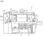
図1から図4を参照して、第1の実施形態について述べる。まず、図2は、本実施形態に係る電動機の本体1の全体構成を概略的に示しており、ここで、電動機本体1は、例えば全体として円筒状をなす金属製のフレーム2内に、固定子3及び回転子4を備えて構成される。前記回転子4には、回転軸5が固定されている。前記固定子3は、固定子鉄心3aに巻線3bを巻装して構成され、フレーム2の内周面に取付けられている。前記回転子4は、例えばかご型回転子からなり、前記固定子3の内周部に配置されている。
(1) First embodiment A first embodiment will be described with reference to Figures 1 to 4. First, Figure 2 shows a schematic diagram of the overall configuration of a
図2に一部のみ示すように、前記フレーム2の外周面には、軸方向すなわち前後方向に延びて、複数本の放熱フィン6が例えば一体的に設けられている。このフレーム2の前後両端には、金属製のモータブラケット7、8が設けられている。図2に示すように、これらモータブラケット7、8には、夫々軸受9、10が取付けられている。これら軸受9、10により、前記回転軸5が回転自在に支持されている。図1にも示すように、前記回転軸5の後端部は、モータブラケット8から後方に突出しており、その突出端部に、冷却用ファン11が取付けられている。
As shown in FIG. 2, a number of
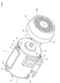
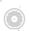
そして、図1等にも示すように、上記電動機本体1の後端部には、前記冷却用ファン11を覆うように板金製のファンカバー12が取付けられる。このファンカバー12は、図4にも示すように、前面が開放したほぼ円筒状をなし、その後面部には、多数個の通風孔12aが設けられている。このファンカバー12は、前端開口部が、前記電動機本体1の後端部外周に被さるようにして取付けられるようになっている。このファンカバー12の取付け構造については後述する。
As shown in Fig. 1 etc., a
ここで、前記フレーム2と、前記モータブラケット7、8との結合構造、特に後部のモータブラケット8との結合構造について述べる。図1~図3に示すように、モータブラケット8の外周部には、円周方向の例えば3箇所に位置し、外周方向に凸となるようにして、矩形ブロック状の取付座13が一体に設けられている。これら取付座13には、ボルト用の挿通穴13aが軸方向に貫通して形成されている。
Here, we will describe the connection structure between the
一方、前記フレーム2の後端部外周部には、前記取付座13に対応した円周方向3箇所に位置して、取付座14が一体に設けられている。これら取付座14は、前記放熱フィン6同士間に位置して、軸方向にやや長いブロック状に設けられると共に、後端面で開口し軸方向に延びるねじ穴14aが形成されている。これにて、モータブラケット8を、その各取付座13が、フレーム2の各取付座14に宛てがわれるように位置合せし、後方からボルト15を挿通穴13aを通してねじ穴14aに締付ける。これにより、モータブラケット8がフレーム2に結合される。前側のモータブラケット7についても、前後に対称的な同様の結合構造で結合される。
On the other hand,
さて、前記電動機本体1に対するファンカバー12の取付け構造について説明する。本実施形態では、図1、図3に示すように、前記ファンカバー12には、開口端部側に位置して係合穴16が設けられている。この係合穴16は、円周方向の3箇所つまり前記取付座13に対応する位置に設けられている。これに対し、前記後部のモータブラケット8の外周面、この場合前記各取付座13の外周面には、凸状の係合突起17が例えば一体に設けられている。この場合、図3に示すように、係合突起17は円形つまり円柱状に設けられている。
Now, the mounting structure of the
これにて、図1、図2に示すように、ファンカバー12の開口端部が、電動機本体1の後端部外周面に被さるようにして、ファンカバー12に設けられた係合穴16が、後部のモータブラケット8の外周面に設けられた係合突起17に対し、円周方向の3箇所で係合することにより、ファンカバー12が電動機本体1に対し取付けられる。また、例えばメンテナンス時などにおいては、ファンカバー12の係合穴16を、モータブラケット8の係合突起17から抜出すようにすることにより、ファンカバー12を電動機本体1から容易に取外すことができる。
As shown in Figures 1 and 2, the open end of the
このような本実施形態の電動機本体1に対するファンカバー12の取付け構造によれば、次のような作用、効果を得ることができる。即ち、本実施形態では、後部のモータブラケット8の外周面に設けられた係合突起17に対し、ファンカバー12に設けられた係合穴16が、円周方向の3箇所で係合することにより、ファンカバー12が電動機本体1に取付けられる。
The mounting structure of the
この場合、従来のようなねじ止めを行う場合と異なり、複数個のねじが不要となって部品点数が削減される。しかも、作業を行うにあたって、ねじ止め用の工具が不要となると共に、ねじ止めの場合と比較して工数が低減され、誰が行っても同等の作業品質で取付けを行うことができる。従って、本実施形態によれば、冷却用ファン11を備えるものにあって、ファンカバー12の取付けの構造の簡単化や、取付作業性の向上を図ることができるという優れた効果を得ることができる。
In this case, unlike conventional screw fastening, multiple screws are not required, and the number of parts is reduced. Furthermore, no tools are required for screw fastening, and the labor required is reduced compared to screw fastening, so that anyone can install the product with the same quality of work. Therefore, according to this embodiment, when used with a
特に本実施形態では、フレーム2とモータブラケット8とをボルト15により結合するための取付座13の外周に、係合突起17を設ける構成とした。これにより、元々設けられる取付座13に係合突起17を設けるものであるから、係合突起17を容易に設けることができる。また、取付座13の全体としての径方向寸法を徒に大きくすることもない。さらに、ファンカバー12の取付け作業時には、作業者にとって係合突起17の位置が判りやすいものとすることができる。
In particular, in this embodiment, the
ところで、従来のねじ止め構造では、モータブラケット又はフレームに設けられた取付座の外周面に、直径方向に延びるねじ穴を形成することから、取付座自体の大きさが直径方向に高くなる事情があった。そのため、フレームやファンカバー自体が外周方向に大型化すると共に、ファンカバーの内周部の取付座周辺やフィン間の例えば人の手指が入るような大きな隙間が形成されてしまう事情もあった。これに対し、本実施形態の構成では、取付座13、14に直径方向のねじ穴が不要で、取付座13、14自体が径方向にさほど大きくなることはないので、ファンカバー12の小型化、人の手指が入る隙間の減少、ひいては安全性の向上を図ることができる。
However, in conventional screw fastening structures, a screw hole extending in the diameter direction is formed on the outer periphery of the mounting seat provided on the motor bracket or frame, which means that the size of the mounting seat itself is large in the diameter direction. This means that the frame and fan cover themselves become larger in the outer periphery, and large gaps are formed around the mounting seat on the inner periphery of the fan cover and between the fins, large enough for a person's fingers to fit in, for example. In contrast, in the configuration of this embodiment, no screw hole is required in the diameter direction in the
(2)第2の実施形態
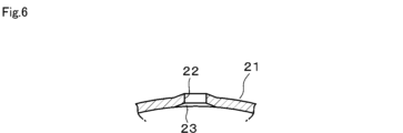
図5及び図6は、第2の実施形態におけるファンカバー21の要部構成を示しており、上記第1の実施形態と異なる点は、次の構成にある。即ち、板金製のファンカバー21は、前面が開放したほぼ円筒状をなし、円周方向の3箇所に開口端部側に位置して係合穴22が設けられている。上記第1の実施形態と同様に、ファンカバー21の開口端部が、電動機本体1の後端部外周面に軸方向に被さるようにして、前記係合穴22が、後部のモータブラケット8の外周面に設けられた係合突起17に対し、円周方向の3箇所で係合することにより、ファンカバー21が電動機本体1に対し取付けられる。
5 and 6 show the main configuration of the
このとき、本実施形態では、前記ファンカバー21の内周面には、該ファンカバー21の開口端部から前記係合穴22まで軸方向に直線的に延びて、前記係合突起17を相対的にガイドするガイド溝23が設けられている。この構成によれば、ファンカバー21を電動機本体1に取付けるにあたって、係合突起17を、ファンカバー21のガイド溝23に沿うようにしながら、軸方向にはめ込むことができる。
In this embodiment, the inner peripheral surface of the
従って、この第2の実施形態によれば、上記第1の実施形態と同様に、冷却用ファン11を備えるものにあって、ファンカバー12の取付けの構造の簡単化や、取付作業性の向上を図ることができるという優れた効果を得ることができる。そして、ファンカバー21にガイド溝23を設けたことにより、ファンカバー21の取付作業途中における係合穴22と係合突起17との間の円周方向の位置ズレを抑制することができ、より一層の作業性の向上を図ることができる。
Therefore, according to this second embodiment, as with the first embodiment, it is possible to obtain the excellent effects of simplifying the structure for mounting the
(3)第3の実施形態
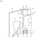
図7は、第3の実施形態を示すもので、電動機本体1に対するファンカバー31の取付け構成を示している。即ち、本実施形態では、電動機本体1のフレーム2の後端部に設けられる後部のモータブラケット32には、円周方向の複数箇所に位置して、外周方向に凸となるように取付座33が一体に設けられている。この取付座33の外周面は、全体として、ファンカバー31の前端部内周面に対応した仮想円に沿うように位置している。そして、モータブラケット32の取付座33の外周面には、回転軸5の中心軸を中心とした雄ねじ状の第1ねじ部34が設けられている。
(3) Third embodiment Fig. 7 shows a third embodiment, illustrating a mounting configuration of a
これに対し、前記ファンカバー31は、板金から前面が開放したほぼ円筒状に構成され、その開口側端部つまり前端部の内周面に、円周方向全周にわたって、前記第1ねじ部34に螺合する雌ねじ状の第2ねじ部35が設けられている。これにて、ファンカバー31が電動機本体1の後端部のモータブラケット32の外周面に対し、スクリューキャップ状に着脱される構成とされている。
The
上記構成においては、ファンカバー31の第2ねじ部35を、後部のモータブラケット32の外周面の第1ねじ部34にねじ込むことにより、ファンカバー31を電動機本体1の後部に取付けることができる。また、ファンカバー31を螺退させることにより、電動機本体1から取外すことができる。
In the above configuration, the
このとき、ねじ止めを行う場合と異なり、複数個のねじが不要となって部品点数が削減される。しかも、作業を行うにあたって、ねじ止め用の工具が不要となると共に、ねじ止めの場合と比較して工数が低減され、誰が行っても同等の作業品質で取付けを行うことができる。従って、この第3の実施形態によれば、冷却用ファン11を備えるものにあって、ファンカバー31の取付けの構造の簡単化や、取付作業性の向上を図ることができるという優れた効果を得ることができる。尚、第1ねじ部34はモータブラケット32の外周面に円周方向に間欠的に設けられているが、全周に渡って設ける構成としても良い。
In this case, unlike when screws are used, multiple screws are not required, and the number of parts is reduced. Moreover, no tools are required for screwing, and the labor costs are reduced compared to when screws are used, so that anyone can install the product with the same quality. Therefore, according to the third embodiment, when used with a cooling
(4)第4の実施形態
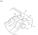
図8は、第4の実施形態を示すものであり、上記第1の実施形態と異なるところは、次の点にある。即ち、この第4の実施形態では、電動機本体1のフレーム41の後端部外周部には、モータブラケット8の取付座13に対応して、結合用の取付座42が一体に設けられている。図示はしないが、取付座42には、後端面で開口し軸方向に延びるねじ穴が形成されており、モータブラケット8は、取付座42のねじ穴に対して、取付座13の挿通穴を通してボルト15を締付けることにより、フレーム41に結合される。
(4) Fourth embodiment Fig. 8 shows a fourth embodiment, which differs from the first embodiment in the following respects: In the fourth embodiment, a mounting
そして、本実施形態では、前記取付座42の外周面には、前記ファンカバー12の先端部が当接して軸方向の位置決めを行うためのストッパ43が一体に設けられている。この第4の実施形態の構成によれば、ファンカバー12の先端部を、ストッパ43に当接させることで、軸方向の位置決めを図ることができる。従って、ファンカバー12の取付け作業時に軸方向に行き過ぎて戻すようにやり直すといったことを未然に防止することができ、取付け作業がより容易となる。取付け後のファンカバー21の軸方向のずれ動きを防止する効果も得られる。
In this embodiment, a
(5)その他の実施形態
図9は、他の実施形態を示すものであり、フレーム2の後端部外周面又は後部のモータブラケット8の外周面に設けられる凸状の係合突起の形状のいくつかの例を示している。上記第1の実施形態では、円柱状の係合突起17を設けるようにしたが、四角形状の係合突起51、三角形状の係合突起52、円錐台形状の係合突起53、山形の係合突起54など、様々な形状とすることができる。上記第1の実施形態等では、係合突起17を後部のモータブラケット8に設けるようにしたが、フレーム2の後端部外周面に設ける構成としても良い。
(5) Other embodiments Fig. 9 shows other embodiments, illustrating several examples of the shapes of the convex engagement protrusions provided on the outer peripheral surface of the rear end portion of the
その他、上記実施形態では、係合突起及び係合穴を、円周方向の3箇所に設けるようにしたが、円周方向の4箇所、更には5箇所以上に設ける構成としても良い。フレームに対するモータブラケットの結合構造としても、例えばボルトとナットを用いて結合する構成としても良い等、適宜変更することができる。ファンカバーの形状や通風孔の構成についても、種々の変更が可能であり、電動機本体のフレームについても、放熱フィンの形状や構造等について、様々な変更が可能であり、放熱フィンを備えないものでも良い。 In addition, in the above embodiment, the engagement protrusions and engagement holes are provided at three circumferential locations, but they may be provided at four or even five or more circumferential locations. The structure of the motor bracket attached to the frame can also be modified as appropriate, for example by using bolts and nuts for attachment. Various modifications are possible for the shape of the fan cover and the configuration of the ventilation holes, and various modifications are possible for the shape and structure of the heat dissipation fins of the frame of the motor body, and it may not even be provided with heat dissipation fins.
本発明のいくつかの実施形態を説明したが、これらの実施形態は例として提示したものであり、発明の範囲を限定することは意図していない。これら新規な実施形態は、その他の様々な形態で実施されることが可能であり、発明の要旨を逸脱しない範囲で種々の省略、置き換え、変更を行うことができる。これらの実施形態やその変形は、発明の範囲や要旨に含まれると共に、特許請求の範囲に記載された発明とその均等の範囲に含まれる。 Although several embodiments of the present invention have been described, these embodiments are presented as examples and are not intended to limit the scope of the invention. These novel embodiments can be embodied in various other forms, and various omissions, substitutions, and modifications can be made without departing from the gist of the invention. These embodiments and their modifications are included within the scope and gist of the invention, as well as within the scope of the invention and its equivalents as set forth in the claims.
図面中、1は電動機本体、2、41はフレーム、3は固定子、4は回転子、5は回転軸、6は放熱フィン、7、8、32はモータブラケット、11は冷却用ファン、12、21、31はファンカバー、13、33は取付座、14、42は取付座、16、22は係合穴、17、51、52、53、54は係合突起、23はガイド溝、34は第1ねじ部、35は第2ねじ部、43はストッパを示す。 In the drawings, 1 indicates the motor body, 2 and 41 indicate frames, 3 indicates a stator, 4 indicates a rotor, 5 indicates a rotating shaft, 6 indicates a heat dissipation fin, 7, 8 and 32 indicate a motor bracket, 11 indicates a cooling fan, 12, 21 and 31 indicate fan covers, 13 and 33 indicate mounting seats, 14 and 42 indicate mounting seats, 16 and 22 indicate engagement holes, 17, 51, 52, 53 and 54 indicate engagement protrusions, 23 indicates a guide groove, 34 indicates a first screw portion, 35 indicates a second screw portion and 43 indicates a stopper.
Claims (1)
前記回転軸の前記後部のモータブラケットから後方に突出する部分に設けられた冷却用ファンと、
前面が開口した円筒状をなし、前記電動機本体の後部に前記冷却用ファンを覆うように設けられるファンカバーとを備え、
前記ファンカバーは、開口端部側に位置して係合穴が設けられると共に、
前記後部のモータブラケットの外周面に、凸状の係合突起が設けられ、
前記ファンカバーの開口端部が、前記電動機本体の後端部外周面に被さるようにして、前記係合穴が前記係合突起に対し、円周方向の3箇所以上で係合することにより取付けられており、
前記ファンカバーの内周面には、該ファンカバーの開口端部から前記係合穴まで軸方向に延びて、前記係合突起を相対的にガイドするガイド溝が設けられており、
前記後部のモータブラケットの外周部には、前記フレームと後部のモータブラケットとをボルトにより結合するための取付座が円周方向の3箇所以上に設けられ、前記係合突起は、前記取付座の外周面に設けられており、
前記フレームの後端部の外周面に、前記ファンカバーの先端部が当接して軸方向の位置決めを行うためのストッパが設けられており、
前記ストッパは、前記フレームの後端部の外周面であって前記取付座に対応した円周方向の3箇所以上に形成された結合用の取付座の外周面に設けられ、周方向に長い矩形ブロック状に形成されている、
電動機。 an electric motor body having motor brackets supporting a rotating shaft on both the front and rear sides of a cylindrical frame;
a cooling fan provided on a portion of the rotating shaft protruding rearward from the rear motor bracket;
a fan cover having a cylindrical shape with an open front surface and provided at a rear portion of the motor body so as to cover the cooling fan,
The fan cover is provided with an engagement hole located on an open end side,
A convex engagement projection is provided on an outer circumferential surface of the rear motor bracket,
The fan cover is attached by having an open end portion of the fan cover cover an outer peripheral surface of a rear end portion of the motor body, and the engagement holes are engaged with the engagement protrusions at three or more points in a circumferential direction,
a guide groove is provided on an inner peripheral surface of the fan cover, the guide groove extending in an axial direction from an open end of the fan cover to the engagement hole and guiding the engagement projection relatively;
an outer periphery of the rear motor bracket is provided with mounting seats at three or more locations in a circumferential direction for fastening the frame and the rear motor bracket with bolts, and the engagement projection is provided on an outer periphery of the mounting seats;
a stopper is provided on an outer peripheral surface of a rear end portion of the frame to abut against a tip end of the fan cover for axial positioning,
The stopper is provided on the outer peripheral surface of a joining mounting seat formed on the outer peripheral surface of the rear end portion of the frame at three or more locations in the circumferential direction corresponding to the mounting seat, and is formed in a rectangular block shape that is long in the circumferential direction.
Electric motor.
Priority Applications (1)
| Application Number | Priority Date | Filing Date | Title |
|---|---|---|---|
| JP2021010343A JP7652575B2 (en) | 2021-01-26 | 2021-01-26 | Electric motor |
Applications Claiming Priority (1)
| Application Number | Priority Date | Filing Date | Title |
|---|---|---|---|
| JP2021010343A JP7652575B2 (en) | 2021-01-26 | 2021-01-26 | Electric motor |
Publications (2)
| Publication Number | Publication Date |
|---|---|
| JP2022114169A JP2022114169A (en) | 2022-08-05 |
| JP7652575B2 true JP7652575B2 (en) | 2025-03-27 |
Family
ID=82658448
Family Applications (1)
| Application Number | Title | Priority Date | Filing Date |
|---|---|---|---|
| JP2021010343A Active JP7652575B2 (en) | 2021-01-26 | 2021-01-26 | Electric motor |
Country Status (1)
| Country | Link |
|---|---|
| JP (1) | JP7652575B2 (en) |
Citations (3)
| Publication number | Priority date | Publication date | Assignee | Title |
|---|---|---|---|---|
| JP2003206896A (en) | 2002-01-16 | 2003-07-25 | Toshiba Tec Corp | Electric blower and vacuum cleaner |
| DE102004015241A1 (en) | 2004-03-29 | 2005-10-20 | Siemens Ag | Air-cooled electrical machine has fan hood fixed onto housing of electrical machine or onto bearing plate by latching device |
| CN211321075U (en) | 2020-03-17 | 2020-08-21 | 新界泵业(浙江)有限公司 | Improved pump motor |
-
2021
- 2021-01-26 JP JP2021010343A patent/JP7652575B2/en active Active
Patent Citations (3)
| Publication number | Priority date | Publication date | Assignee | Title |
|---|---|---|---|---|
| JP2003206896A (en) | 2002-01-16 | 2003-07-25 | Toshiba Tec Corp | Electric blower and vacuum cleaner |
| DE102004015241A1 (en) | 2004-03-29 | 2005-10-20 | Siemens Ag | Air-cooled electrical machine has fan hood fixed onto housing of electrical machine or onto bearing plate by latching device |
| CN211321075U (en) | 2020-03-17 | 2020-08-21 | 新界泵业(浙江)有限公司 | Improved pump motor |
Also Published As
| Publication number | Publication date |
|---|---|
| JP2022114169A (en) | 2022-08-05 |
Similar Documents
| Publication | Publication Date | Title |
|---|---|---|
| DE102008028607B4 (en) | electric motor | |
| WO1999021265A1 (en) | Ac generator for vehicle | |
| US10523082B2 (en) | Bearing assembly for electrical generator | |
| US8089189B2 (en) | Rotor for permanent magnet electric machine | |
| DE102010024302B4 (en) | Electric motor and method for manufacturing an electric motor | |
| JP7652575B2 (en) | Electric motor | |
| JP6007084B2 (en) | Electric motor and fan motor | |
| DE102011103853A1 (en) | Electric motor e.g. synchronous motor, for vehicle, has stator arranged in pot-shaped housing portion and connected with housing portion in force-fit manner, and rotor shaft whose bearing is arranged at bottom part of housing portion | |
| JP2015089173A (en) | Rotary electric machine | |
| JP6758359B2 (en) | Rotating electric machine | |
| US20020047476A1 (en) | Rotary electric machine having stator rotation-restricting bolt | |
| TWI712250B (en) | Motor housing and motor | |
| JP2010074951A (en) | Rotor of outer rotor type rotating electric machine | |
| CN214837925U (en) | Transmission mechanism, bearing transmission structure and bearing seat | |
| JP2006038808A (en) | Resolver stator fixing structure | |
| US9219386B2 (en) | Motor's stator unit | |
| JP7132722B2 (en) | Encoder anti-rotation structure | |
| CN102160262A (en) | Modularized elongation ring for air outlet in self-ventilated traction motor | |
| JPS6223236Y2 (en) | ||
| KR200439889Y1 (en) | Motor coupling structure of cooling fan | |
| CN220586065U (en) | Motor rear end cover structure, motor housing, motor and electric drive axle | |
| CN222638262U (en) | An easy-to-assemble hub motor end cover clamp base connection mechanism | |
| CN110971050A (en) | Combined end cover for motor and motor with combined end cover | |
| JP5029524B2 (en) | Vehicle auxiliary equipment | |
| KR20080000346U (en) | Fan motor gear |
Legal Events
| Date | Code | Title | Description |
|---|---|---|---|
| A621 | Written request for application examination |
Free format text: JAPANESE INTERMEDIATE CODE: A621 Effective date: 20231102 |
|
| A977 | Report on retrieval |
Free format text: JAPANESE INTERMEDIATE CODE: A971007 Effective date: 20240523 |
|
| A131 | Notification of reasons for refusal |
Free format text: JAPANESE INTERMEDIATE CODE: A131 Effective date: 20240604 |
|
| A521 | Request for written amendment filed |
Free format text: JAPANESE INTERMEDIATE CODE: A523 Effective date: 20240705 |
|
| A131 | Notification of reasons for refusal |
Free format text: JAPANESE INTERMEDIATE CODE: A131 Effective date: 20240910 |
|
| A521 | Request for written amendment filed |
Free format text: JAPANESE INTERMEDIATE CODE: A523 Effective date: 20241105 |
|
| TRDD | Decision of grant or rejection written | ||
| A01 | Written decision to grant a patent or to grant a registration (utility model) |
Free format text: JAPANESE INTERMEDIATE CODE: A01 Effective date: 20250218 |
|
| A61 | First payment of annual fees (during grant procedure) |
Free format text: JAPANESE INTERMEDIATE CODE: A61 Effective date: 20250314 |
|
| R150 | Certificate of patent or registration of utility model |
Ref document number: 7652575 Country of ref document: JP Free format text: JAPANESE INTERMEDIATE CODE: R150 |