JP7651237B2 - Light guide plate - Google Patents
Light guide plate Download PDFInfo
- Publication number
- JP7651237B2 JP7651237B2 JP2021058956A JP2021058956A JP7651237B2 JP 7651237 B2 JP7651237 B2 JP 7651237B2 JP 2021058956 A JP2021058956 A JP 2021058956A JP 2021058956 A JP2021058956 A JP 2021058956A JP 7651237 B2 JP7651237 B2 JP 7651237B2
- Authority
- JP
- Japan
- Prior art keywords
- light
- light guide
- incident
- guide plate
- deflection element
- Prior art date
- Legal status (The legal status is an assumption and is not a legal conclusion. Google has not performed a legal analysis and makes no representation as to the accuracy of the status listed.)
- Active
Links
- 238000010586 diagram Methods 0.000 description 24
- 230000007423 decrease Effects 0.000 description 20
- 230000006866 deterioration Effects 0.000 description 16
- 102220492401 Ribulose-phosphate 3-epimerase_L12A_mutation Human genes 0.000 description 15
- 102100023247 60S ribosomal protein L23a Human genes 0.000 description 10
- 101001115494 Homo sapiens 60S ribosomal protein L23a Proteins 0.000 description 10
- 230000003287 optical effect Effects 0.000 description 10
- 239000003086 colorant Substances 0.000 description 3
- 230000000694 effects Effects 0.000 description 3
- 239000011521 glass Substances 0.000 description 3
- 230000015556 catabolic process Effects 0.000 description 2
- 238000006731 degradation reaction Methods 0.000 description 2
- 230000004048 modification Effects 0.000 description 2
- 238000012986 modification Methods 0.000 description 2
- 239000004925 Acrylic resin Substances 0.000 description 1
- 229920000178 Acrylic resin Polymers 0.000 description 1
- 230000005540 biological transmission Effects 0.000 description 1
- 238000009434 installation Methods 0.000 description 1
- 230000001678 irradiating effect Effects 0.000 description 1
- 239000004973 liquid crystal related substance Substances 0.000 description 1
- 239000000463 material Substances 0.000 description 1
- 230000001902 propagating effect Effects 0.000 description 1
- 239000011347 resin Substances 0.000 description 1
- 229920005989 resin Polymers 0.000 description 1
Images


Landscapes
- Instrument Panels (AREA)
Description
本発明は、導光板、および、表示装置に関する。 The present invention relates to a light guide plate and a display device.
表示画像の広画角化を図り得る光学装置が開示されている(特許文献1参照)。上記光学装置は、導光板内に複数のホログラム素子を有する。 An optical device that can widen the angle of view of a displayed image has been disclosed (see Patent Document 1). The optical device has multiple hologram elements inside a light guide plate.
しかしながら、導光板を用いて表示される画像の品質が低下することがある。 However, the quality of images displayed using a light guide plate can sometimes be degraded.
そこで、本発明は、表示される画像の品質の低下を抑制する導光板などを提供することを目的とする。 Therefore, the present invention aims to provide a light guide plate or the like that prevents deterioration in the quality of the displayed image.
本発明の一態様に係る導光板は、第一導光体と、第二導光体と、入射光に含まれる第一波長成分の光を選択的に偏向することで前記第一導光体に入射させる第一偏向素子と、前記入射光に含まれる第二波長成分の光を選択的に偏向することで前記第二導光体に入射させる第二偏向素子とを備える導光板である。 A light guide plate according to one aspect of the present invention is a light guide plate including a first light guide, a second light guide, a first deflection element that selectively deflects light of a first wavelength component contained in the incident light so that it is incident on the first light guide, and a second deflection element that selectively deflects light of a second wavelength component contained in the incident light so that it is incident on the second light guide.
本発明に係る導光板は、表示される画像の品質の低下を抑制することができる。 The light guide plate of the present invention can suppress deterioration in the quality of the displayed image.
(本発明の基礎となった知見)
車両のウィンドシールド(一般にフロントガラスともよばれる)などの透明板に画像を投影し、透明板の向こう側の景色とともに当該画像を運転者などのユーザに視認させる表示装置がある。このような表示装置は、一般に、ヘッドアップディスプレイ装置ともよばれる。
(Findings on which the present invention is based)
There is a display device that projects an image onto a transparent plate such as a windshield (commonly called a front glass) of a vehicle, and allows a user such as a driver to view the image together with the scenery on the other side of the transparent plate. Such a display device is generally also called a head-up display device.
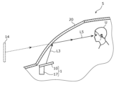
図1は、表示装置1が設置される車両の一例である車両5を示す模式図である。図2は、表示装置1の構成を示す模式図である。
Figure 1 is a schematic diagram showing a
図1に示されるように、車両5は、表示装置1と、ウィンドシールド20とを備える。表示装置1は、例えば、ウィンドシールド20の下部に設置され、上方つまりウィンドシールド20に向けて、画像の表示に係る光(表示光ともいう)を出射する。表示装置1は、例えばダッシュボードの内部に設置される。表示装置1が出射する表示光の光路は確保されており、言い換えれば、出射された表示光は、遮られずにウィンドシールド20に到達する。表示装置1の構成について、より詳しく説明する。
As shown in FIG. 1, the
図2に示されるように、表示装置1は、導光板10と、画像生成装置17とを備える。
As shown in FIG. 2, the
画像生成装置17は、表示光を生成して導光板10に提供する装置である。画像生成装置17は、例えば、画像生成装置17が有する光源(不図示)から出射された光を、液晶などの画像形成素子に照射することで表示光を生成する。画像生成装置17は、生成した表示光を導光板10に向けて出射する。
The image generating device 17 is a device that generates display light and provides it to the
導光板10は、画像生成装置17が生成した表示光のビーム幅を拡大しながら偏向する板体である。ここで、ビーム幅とは、光の進行方向に対して垂直な方向における光束の幅を意味する。
The
導光板10には、画像生成装置17が生成した表示光が入射される。入射された表示光は、導光板10内で導光され、導光板10の外部に光L3として出射される。光L3は、ウィンドシールド20により反射されて光L5となり、ユーザUの眼に入射する。導光板10は、光L3がウィンドシールド20に向けて出射される位置および姿勢で設置されている。
Display light generated by the image generating device 17 is incident on the
導光板10による表示光のビーム幅の拡大と偏向とは、導光板10が有する複数の回折素子を用いてなされる。そのため、導光板10が有する複数の回折素子それぞれは、表示光を適切な方向に回折する回折特性を有し、また、適切な寸法を有している。
The expansion and deflection of the beam width of the display light by the
ユーザUは、表示光である光L5が目に入射したことにより、画像生成装置17が生成した画像を視認する。ユーザUは、表示光である光L5によって視認する画像を、ウィンドシールド20の向こう側に位置する虚像14として認識する。
When the light L5, which is the display light, enters the user U's eyes, the user U sees the image generated by the image generating device 17. The user U recognizes the image seen by the light L5, which is the display light, as a
導光板10が有する上記の機能は、凹面鏡などの光学部材によっても実現され得る。ただし、凹面鏡などの光学部材によって実現する場合よりも、導光板10を用いるほうが、表示装置1の寸法を小さくすることができる利点がある。表示装置1は、車両5の例えばダッシュボード内部に設置されるので、寸法を小さくすることで、設置の自由度がより高くなる利点がある。
The above-mentioned functions of the
しかしながら、導光板10を用いて表示される画像の品質が低下することがある。具体的には、導光板10が複数の導光体を用いて複数の波長の光を導光する場合に、光の強度の低下、または、迷光の発生により、表示装置1によって表示される画像の品質が低下することがある。
However, the quality of the image displayed using the
以降において、光の強度の低下、または、迷光の発生による表示画像の品質の低下について詳しく説明する。このような表示画像の品質の低下を生じさせる導光板を導光板90と称する。 The following describes in detail the degradation of the quality of the displayed image caused by a decrease in light intensity or the occurrence of stray light. A light guide plate that causes such degradation in the quality of the displayed image is referred to as a light guide plate 90.
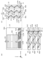
図3は、関連技術に係る導光板90の構成を示す模式図である。図3の(a)は、導光板90を上面視した場合、つまり、Z軸プラス方向から見た構成を示す図である。図3の(b)は、導光板90を側面視した場合、つまり、Y軸マイナス方向から見た場合の構成を示す図である。図3の(c)は、導光板90を側面視した場合、つまり、X軸プラス方向から見た場合の構成を示す図である。 Figure 3 is a schematic diagram showing the configuration of a light guide plate 90 according to related technology. (a) of Figure 3 is a diagram showing the configuration when the light guide plate 90 is viewed from above, that is, when viewed from the positive direction of the Z axis. (b) of Figure 3 is a diagram showing the configuration when the light guide plate 90 is viewed from the side, that is, when viewed from the negative direction of the Y axis. (c) of Figure 3 is a diagram showing the configuration when the light guide plate 90 is viewed from the side, that is, when viewed from the positive direction of the X axis.
図3の(b)および(c)に示されるように導光板90は、導光体90A、90Bおよび90C(導光体90A等ともいう)を備える。導光体90A等は、互いに平行する姿勢で配置されており、上面視において重なる位置に配置されている。また、導光体90A等は、上面視において同じ形状、例えば矩形形状を有するが、これに限定されない。
3(b) and (c), the light guide plate 90 includes
図3の(a)は、上記導光体90A等のうち導光体90Aのみを示すものである。導光体90Bおよび90Cについても図3の(a)と同様の説明が成立する。
Figure 3(a) shows only
図3に示されるように、導光体90Aは、透明部材15を有し、透明部材15の内部または表面にホログラム素子91A、12Aおよび13A(ホログラム素子91A等ともいう)を有する板体である。導光体90Aは、入射された光L1を導光体90A内部で全反射によって導光し、また、ホログラム素子91A等による回折によって偏向された光を、導光体90Aの外部に光L3Aとして出射する。透明部材15は、ガラスまたはアクリル樹脂などで構成されている。
As shown in FIG. 3, the
導光体90Aに入射される光L1は、Y軸プラス方向およびZ軸プラス方向に進行する光である。光L1は、画像生成装置17が生成した表示光であることが想定され、この場合、複数の波長成分の光(例えば、赤色、緑色および青色の波長成分の光)を含む。導光体90Aは、表示装置1の使用状態(つまり、表示装置1が図2に示されるように設置された状態)において、図3に示されるような適切な角度で光L1が入射される位置および姿勢で設置されている。
Light L1 incident on
ホログラム素子91Aは、導光体90Aの内部または表面に配置されている回折素子である。ホログラム素子91Aは、導光体90Aの外部から内部へ入射した光L1を回折によって偏向することで、導光体90Aの内部で伝搬させる。ホログラム素子91Aは、上面視において直線状の干渉縞が形成されており、干渉縞による回折によって光L1を偏向し、光L12AおよびLAとする。光L12Aは、X軸マイナス方向へ進行する光であって、特定の周波数成分の光(例えば、赤色に相当する周波数成分の光)である。光L12Aは、透明部材15と空気との界面で全反射を繰り返すことで導光体90A内部をX軸マイナス方向へ伝搬する。
The
ホログラム素子91Aに形成されている干渉縞は、光L12Aが透明部材15と空気との界面で全反射をするように光L1を偏向させる干渉縞である。上記干渉縞は、具体的には、界面への光L12Aの入射角が臨界角より大きい状態を保つように、光L1を偏向させる。
The interference fringes formed on the
また、光LAは、X軸マイナス方向へ進行する光であって、上記特定の周波数成分以外の周波数成分の光(例えば、青色および緑色に相当する周波数成分の光)である。光LAは、光L1がホログラム素子91Aにより回折された際に、周波数ごとに回折角がばらつくことに起因して生ずる光である。光LAは、上記干渉縞によって回折された場合、透明部材15と空気との界面で全反射をする場合もあればしない場合もあり、迷光となる。
Light LA is light that travels in the negative direction of the X-axis and is light with a frequency component other than the specific frequency components (for example, light with frequency components corresponding to blue and green). Light LA is light that is generated when light L1 is diffracted by
ホログラム素子12Aは、導光体90Aの内部または表面に配置されている回折素子である。ホログラム素子12Aは、ホログラム素子91Aによって偏向された光L12Aを、回折によって偏向することで、導光体90Aの内部で伝搬させる。ホログラム素子12Aは、上面視において直線状の干渉縞が形成されており、干渉縞による回折によって光L12Aを偏向し、光L23Aとする。光L23Aは、Y軸プラス方向へ進行する光である。光L23Aは、透明部材15と空気との界面で全反射を繰り返すことで導光体90A内部をY軸プラス方向へ伝搬する。
The
ホログラム素子12Aに形成されている干渉縞は、光L23Aが透明部材15と空気との界面で全反射をするように光L12Aを偏向させる干渉縞である。上記干渉縞は、具体的には、界面への光L23Aの入射角が臨界角より大きい状態を保つように、光L12Aを偏向させる。
The interference fringes formed on the
ホログラム素子13Aは、導光体90Aの内部または表面に配置されている回折素子である。ホログラム素子13Aは、ホログラム素子12Aによって偏向された光L23Aを、回折によって偏向することで、導光体90Aの外部へ出射させる。ホログラム素子13Aは、上面視において直線状の干渉縞が形成されており、干渉縞による回折によって光L23Aを偏向し、光L3Aとする。光L3Aは、Y軸プラス方向およびZ軸プラス方向へ進行する光である。
ホログラム素子13Aに形成されている干渉縞は、光L3Aが透明部材15と空気との界面で、全反射せずに、光L3Aが導光体90Aから出射するように光L23Aを偏向させる干渉縞である。上記干渉縞は、具体的には、界面への光L3Aの入射角が臨界角より小さい状態を保つように、光L23Aを偏向させる。
The interference fringes formed on the
導光体90Aは、表示装置1の使用状態で、出射する光L3Aがウィンドシールド20に向かう位置および姿勢で設置されている。
The
導光体90Bについても導光体90Aと同様である。導光体90Bには、ホログラム素子91Aを透過した光L1Bが入射する。導光体90Bは、入射した光L1Bを偏向し、その特定の周波数成分の光(例えば、緑色に相当する周波数成分の光)をホログラム素子91B、12Bおよび13Bによって順次に回折して光L3Bを出射する。その際、導光体90Bは、迷光となる光LBを発生させる。
The
導光体90Cについても導光体90Aと同様である。導光体90Cには、ホログラム素子91Bを透過した光L1Cが入射する。導光体90Cは、入射した光L1Cを偏向し、その特定の周波数成分の光(例えば、青色に相当する周波数成分の光)をホログラム素子91C、12Cおよび13Cによって順次に回折して光L3Cを出射する。その際、導光体90Cは、迷光となる光LCを発生させる。
The
光L3A、L3BおよびL3Cは、光L3となり導光板90から出射される。導光板90から出射された後にウィンドシールド20による反射を経てユーザUの眼に入射する。
Light L3A, L3B, and L3C become light L3 and are emitted from the light guide plate 90. After being emitted from the light guide plate 90, the light is reflected by the
ここで、光L1Bは、ホログラム素子91Aにより回折された光であるので、光L1Bの強度は、光L1の強度より低い。また、光L1Cは、ホログラム素子91Aおよび91Bにより回折された光であるので、光L1の強度より低い。そのため、光L3の強度は光L1の強度より低下している。さらに、光L1がホログラム素子91Aおよび91Bにより回折される際に、迷光である光LA、LBおよびLCが発生する。
Here, since light L1B is light diffracted by
このようにして、導光板90が、入射した光L1を回折する際に、光の強度の低下、または、迷光の発生による表示画像の品質の低下が発生する。 In this way, when the light guide plate 90 diffracts the incident light L1, the intensity of the light decreases, or stray light occurs, causing a decrease in the quality of the displayed image.
そこで、本発明は、表示される画像の品質の低下を抑制する導光板などを提供することを目的とする。 Therefore, the present invention aims to provide a light guide plate or the like that prevents deterioration in the quality of the displayed image.
本発明の一態様に係る導光板は、第一導光体と、第二導光体と、入射光に含まれる第一波長成分の光を選択的に偏向することで前記第一導光体に入射させる第一偏向素子と、前記入射光に含まれる第二波長成分の光を選択的に偏向することで前記第二導光体に入射させる第二偏向素子とを備える導光板である。 A light guide plate according to one aspect of the present invention is a light guide plate including a first light guide, a second light guide, a first deflection element that selectively deflects light of a first wavelength component contained in the incident light so that it is incident on the first light guide, and a second deflection element that selectively deflects light of a second wavelength component contained in the incident light so that it is incident on the second light guide.
上記態様によれば、導光板は、入射光に含まれる2つの波長成分の光それぞれを、偏向素子によって選択的に偏向することで2つの導光体それぞれに入射させるので、光の強度の低下、および、迷光の発生を抑制することができる。このように、導光板は、表示される画像の品質の低下を抑制することができる。 According to the above aspect, the light guide plate selectively deflects the two wavelength components contained in the incident light with a deflection element, causing the light to enter each of the two light guides, thereby suppressing a decrease in light intensity and the occurrence of stray light. In this way, the light guide plate can suppress a decrease in the quality of the displayed image.
また、前記第一偏向素子は、前記入射光に含まれる前記第一波長成分の光を選択的に反射することで前記第一導光体に入射させ、前記入射光に含まれる前記第一波長成分以外の光を透過し、前記第二偏向素子は、前記入射光に含まれる前記第二波長成分の光を選択的に反射することで前記第二導光体に入射させ、前記入射光に含まれる前記第二波長成分以外の光を透過してもよい。 The first deflection element may selectively reflect the light of the first wavelength component contained in the incident light to cause it to enter the first light guide and transmit light other than the first wavelength component contained in the incident light, and the second deflection element may selectively reflect the light of the second wavelength component contained in the incident light to cause it to enter the second light guide and transmit light other than the second wavelength component contained in the incident light.
上記態様によれば、導光板は、入射光に含まれる2つの波長成分の光それぞれを偏向素子による反射を用いて2つの導光体それぞれに入射させるので、光の強度の低下、および、迷光の発生を抑制することができる。このように、導光板は、表示される画像の品質の低下を抑制することができる。 According to the above aspect, the light guide plate causes each of the two wavelength components contained in the incident light to be incident on each of the two light guides by using reflection by the deflection element, so that it is possible to suppress a decrease in light intensity and the occurrence of stray light. In this way, the light guide plate can suppress a decrease in the quality of the displayed image.
また、前記第一波長成分は、赤色に相当する波長成分であり、前記第二波長成分は、緑色に相当する波長成分と青色に相当する波長成分とであってもよい。 The first wavelength component may be a wavelength component corresponding to red, and the second wavelength component may be a wavelength component corresponding to green and a wavelength component corresponding to blue.
上記態様によれば、導光板は、赤色に相当する波長成分を第一導光体に入射させるとともに、緑色および青色に相当する波長成分を第二導光体に入射させることで、赤色、緑色および青色の3つの波長成分を含む光を導光し、上記3つの波長成分を含むフルカラーの表示画像を表示することに寄与する。よって、導光板は、フルカラーの表示画像の品質の低下をより一層抑制することができる。 According to the above aspect, the light guide plate guides light containing the three wavelength components of red, green, and blue by allowing the wavelength component corresponding to red to enter the first light guide and the wavelength components corresponding to green and blue to enter the second light guide, thereby contributing to displaying a full-color display image containing the above three wavelength components. Therefore, the light guide plate can further suppress deterioration in the quality of the full-color display image.
また、前記導光板は、さらに、前記第一偏向素子と前記第二偏向素子とを内部に有する透明部材を備えてもよい。 The light guide plate may further include a transparent member having the first deflection element and the second deflection element therein.
上記態様によれば、導光板は、透明部材が光を透過させながら偏向素子を支持するので、偏向素子の位置をより高い精度で適切な位置に維持することができ、その結果、偏向素子が偏向した光の光路をより適切に維持することができる。この効果は、振動がある環境に導光板が配置される場合には、特に顕著である。これにより、偏向素子の位置が変化することによる光の光路のずれを抑制し、表示される画像の品質の低下を抑制することができる。よって、導光板は、表示される画像の品質の低下をより一層抑制することができる。 According to the above aspect, the light guide plate supports the deflection element while transmitting light through the transparent member, so that the position of the deflection element can be maintained in an appropriate position with higher precision, and as a result, the optical path of the light deflected by the deflection element can be more appropriately maintained. This effect is particularly noticeable when the light guide plate is placed in an environment where vibrations are present. This makes it possible to suppress deviations in the optical path of light caused by changes in the position of the deflection element, and suppress deterioration in the quality of the displayed image. Therefore, the light guide plate can further suppress deterioration in the quality of the displayed image.
また、前記導光板は、さらに、第三導光体と、前記入射光に含まれる第三波長成分の光を前記第三導光体に入射させる第三偏向素子とを備えてもよい。 The light guide plate may further include a third light guide and a third deflection element that causes light of a third wavelength component contained in the incident light to enter the third light guide.
上記態様によれば、導光板は、入射光に含まれる3つの波長成分の光それぞれを、偏向素子によって選択的に偏向することで3つの導光体それぞれに入射させるので、光の強度の低下、および、迷光の発生を抑制することができる。このように、導光板は、表示される画像の品質の低下を抑制することができる。 According to the above aspect, the light guide plate selectively deflects each of the three wavelength components contained in the incident light using a deflection element, causing the light to enter each of the three light guides, thereby suppressing a decrease in light intensity and the occurrence of stray light. In this way, the light guide plate can suppress a decrease in the quality of the displayed image.
また、前記第三偏向素子は、前記入射光に含まれる前記第三波長成分の光を選択的に偏向することで、前記第三導光体に入射させてもよい。 The third deflection element may selectively deflect the third wavelength component of the incident light to cause it to enter the third light guide.
上記態様によれば、導光板は、入射光に含まれる3つの波長成分の光それぞれを偏向素子による反射を用いて3つの導光体それぞれに入射させるので、光の強度の低下、および、迷光の発生を抑制することができる。このように、導光板は、表示される画像の品質の低下を抑制することができる。 According to the above aspect, the light guide plate causes each of the three wavelength components contained in the incident light to be incident on each of the three light guides by using reflection by the deflection element, so that it is possible to suppress a decrease in light intensity and the occurrence of stray light. In this way, the light guide plate can suppress a decrease in the quality of the displayed image.
また、前記第一導光体は、前記第一導光体により導光された光を前記入射光が入射された面と反対側の面から出射し、前記第二導光体は、前記第二導光体により導光された光を前記入射光が入射された面と反対側の面から出射してもよい。 In addition, the first light guide may emit the light guided by the first light guide from a surface opposite to the surface into which the incident light is incident, and the second light guide may emit the light guided by the second light guide from a surface opposite to the surface into which the incident light is incident.
上記態様によれば、導光板は、入射光が入射する面と反対側の面に光を出射するので、入射光を出射する機材(例えば画像生成装置に相当)と、出射した光を受ける機材(例えばウィンドシールドに相当)とが、当該導光板に対して反対側に存在する場合に、両機材の間で適切に光を導光することができる。よって、導光板は、光を適切に導光しながら、表示される画像の品質の低下を抑制することができる。 According to the above aspect, the light guide plate emits light to the surface opposite to the surface on which the incident light is incident. Therefore, when a device that emits the incident light (e.g., an image generating device) and a device that receives the emitted light (e.g., a windshield) are located on opposite sides of the light guide plate, the light can be appropriately guided between the two devices. Therefore, the light guide plate can appropriately guide light while suppressing deterioration in the quality of the displayed image.
また、前記第一導光体は、前記第一導光体により導光された光を前記入射光が入射された面と同じ側の面から出射し、前記第二導光体は、前記第二導光体により導光された光を前記入射光が入射された面と同じ側の面から出射してもよい。 The first light guide may emit the light guided by the first light guide from a surface on the same side as the surface on which the incident light is incident, and the second light guide may emit the light guided by the second light guide from a surface on the same side as the surface on which the incident light is incident.
上記態様によれば、導光板は、入射光が入射する面と同じ側の面に光を出射するので、入射光を出射する機材(例えば画像生成装置に相当)と、出射した光を受ける機材(例えばウィンドシールドに相当)とが、当該導光板に対して同じ側に存在する場合に、両機材の間で適切に光を導光することができる。よって、導光板は、光を適切に導光しながら、表示される画像の品質の低下を抑制することができる。 According to the above aspect, the light guide plate emits light to the same surface as the surface on which the incident light is incident. Therefore, when a device that emits the incident light (e.g., an image generating device) and a device that receives the emitted light (e.g., a windshield) are on the same side of the light guide plate, the light can be appropriately guided between the two devices. Therefore, the light guide plate can appropriately guide light while suppressing deterioration in the quality of the displayed image.
また、本発明の一態様に係る表示装置は、上記の導光板と、画像を示す光を生成して前記導光板に入射させる画像生成装置とを備える表示装置である。 A display device according to one aspect of the present invention is a display device including the above-mentioned light guide plate and an image generating device that generates light representing an image and causes the light to enter the light guide plate.
上記態様によれば、表示装置は、導光板を用いて、表示される画像の品質の低下を抑制することができる。 According to the above aspect, the display device can suppress deterioration in the quality of the displayed image by using a light guide plate.
以下、実施の形態について、図面を参照しながら具体的に説明する。 The following describes the embodiment in detail with reference to the drawings.
なお、以下で説明する実施の形態は、いずれも包括的または具体的な例を示すものである。以下の実施の形態で示される数値、形状、材料、構成要素、構成要素の配置位置及び接続形態、ステップ、ステップの順序などは、一例であり、本発明を限定する主旨ではない。また、以下の実施の形態における構成要素のうち、最上位概念を示す独立請求項に記載されていない構成要素については、任意の構成要素として説明される。 The embodiments described below are all comprehensive or specific examples. The numerical values, shapes, materials, components, component placement and connection forms, steps, and order of steps shown in the following embodiments are merely examples and are not intended to limit the present invention. Furthermore, among the components in the following embodiments, components that are not described in an independent claim that indicates a superordinate concept are described as optional components.
(実施の形態)
本実施の形態において、表示される画像の品質の低下を抑制する導光板および表示装置について説明する。本実施の形態の導光板および表示装置は、車両のウィンドシールドに、画像を投影することで表示する表示装置である。以降の説明において、図に示されるXYZ軸を用いて説明することがある。
(Embodiment)
In this embodiment, a light guide plate and a display device that suppress deterioration of the quality of a displayed image will be described. The light guide plate and the display device of this embodiment are a display device that displays an image by projecting it onto a windshield of a vehicle. In the following description, the XYZ axes shown in the drawings may be used.
図4は、本実施の形態に係る導光板10の構成を示す模式図である。図4の(a)は、導光板10を上面視した場合、つまり、Z軸プラス方向から見た構成を示す図である。図4の(b)は、導光板10を側面視した場合、つまり、Y軸マイナス方向から見た場合の構成を示す図である。図4の(c)は、導光板10を側面視した場合、つまり、X軸プラス方向から見た場合の構成を示す図である。
Figure 4 is a schematic diagram showing the configuration of the
図4に示されるように、導光板10は、入射部10Eと、導光体10A、10Bおよび10C(導光体10A等ともいう)とを備える。導光体10A等は、互いに平行する姿勢で配置されており、上面視において重なる位置に配置されている。また、導光体10A等は、上面視において同じ形状、例えば矩形形状を有するが、これに限定されない。
As shown in FIG. 4, the
図4の(a)は、上記導光体10A等のうち導光体10Aのみを示すものである。導光体10Bおよび10Cについても図4の(a)と同様の説明が成立する。
Figure 4(a) shows only the
図4に示されるように、導光体10Aは、透明部材15を有し、透明部材15の内部または表面にホログラム素子12Aおよび13A(ホログラム素子12A等ともいう)を有する板体である。導光体10Aは、入射された光L1を導光体10A内部で全反射によって導光し、また、ホログラム素子12A等による回折によって偏向された光を、導光体10Aの外部に光L3Aとして出射する。透明部材15は、ガラスまたは樹脂などで構成されている。
As shown in FIG. 4, the
入射部10Eに入射される光L1は、Y軸プラス方向およびZ軸プラス方向に進行する光である。光L1は、画像生成装置17が生成した表示光であることが想定される。導光板10は、表示装置1の使用状態(つまり、表示装置1が図2に示されるように設置された状態)において、図4に示されるような適切な角度で光L1が入射部10Eに入射される位置および姿勢で設置されている。
Light L1 incident on the
入射部10Eは、偏向素子30A、30Bおよび30C(偏向素子30A等ともいう)を有する。入射部10Eは、光L1を偏向素子30A等によって偏向して導光体10A等に入射させる。入射部10Eは、光L1の進行方向において導光体10A等が存在している範囲を包含する幅を有する柱状体(例えば直方体)である。
The
偏向素子30Aは、入射光に含まれる所定の波長成分(第一波長成分ともいう)の光を導光体10Aに入射させる偏向素子である。偏向素子30Aは、入射光に含まれる第一波長成分の光を選択的に偏向することで導光体10Aに入射させる。より具体的には、偏向素子30Aは、入射光に含まれる第一波長成分の光を選択的に反射することで導光体10Aに入射させ、また、入射光に含まれる第一波長成分以外の光を透過する偏向素子である。偏向素子30Aは、波長選択式ミラー(ダイクロイックミラー)により実現され得る。
偏向素子30Aは、導光板10の外部から内部へ入射した光L1を偏向することで光L12Aとし、導光体10Aの内部で伝搬させる。光L12Aは、X軸マイナス方向へ進行する光である。光L12Aは、透明部材15と空気との界面で全反射を繰り返すことで導光体10A内部をX軸マイナス方向へ伝搬する。偏向素子30Aは、界面への光L12Aの入射角が臨界角より大きくなるように、光L1を偏向させる。
The
偏向素子30Bは、入射光に含まれる所定の波長成分(第二波長成分ともいう)の光を導光体10Bに入射させる偏向素子である。偏向素子30Bは、入射光に含まれる第二波長成分の光を選択的に偏向することで導光体10Bに入射させる。より具体的には、偏向素子30Bは、入射光に含まれる第二波長成分の光を選択的に反射することで導光体10Bに入射させ、また、入射光に含まれる第二波長成分以外の光を透過する偏向素子である。偏向素子30Bは、波長選択式ミラー(ダイクロイックミラー)により実現され得る。第二波長成分は、第一波長成分とは異なる。
偏向素子30Bは、偏向素子30Aを透過した光L1Bを偏向することで光L12Bとし、導光体10Bの内部で伝搬させる。光L12Bは、X軸マイナス方向へ進行する光である。光L12Bは、透明部材15と空気との界面で全反射を繰り返すことで導光体10B内部をX軸マイナス方向へ伝搬する。偏向素子30Bは、界面への光L12Bの入射角が臨界角より大きくなるように、光L1Bを偏向させる。
偏向素子30Cは、入射光に含まれる所定の波長成分(第三波長成分ともいう)の光を導光体10Cに入射させる偏向素子である。偏向素子30Cは、入射光に含まれる第三波長成分の光を選択的に偏向することで導光体10Cに入射させる。より具体的には、偏向素子30Cは、入射光に含まれる第三波長成分の光を反射することで導光体10Cに入射させ、また、入射光に含まれる第三波長成分以外の光を透過する偏向素子である。偏向素子30Cは、波長選択式ミラー(ダイクロイックミラー)により実現され得る。第三波長成分は、第一波長成分および第二波長成分のいずれとも異なる。
偏向素子30Cは、偏向素子30Bを透過した光L1Cを偏向することで光L12Cとし、導光体10Cの内部で伝搬させる。光L12Cは、X軸マイナス方向へ進行する光である。光L12Cは、透明部材15と空気との界面で全反射を繰り返すことで導光体10C内部をX軸マイナス方向へ伝搬する。偏向素子30Cは、界面への光L12Cの入射角が臨界角より大きくなるように、光L1Cを偏向させる。
偏向素子30A等は、反射または透過によって、言い換えれば回折を用いないで、光L1、L1BおよびL1Cを偏向するので、周波数ごとの回折角のばらつきが生ずることがない。そのため、図3における迷光である光LA、LBおよびLCに相当する光が発生しない。
The
導光体10Aは、ホログラム素子12Aおよび13Aを備える。導光体10Bは、ホログラム素子12Bおよび13Bを備える。導光体10Cは、ホログラム素子12Cおよび13Cを備える。
ホログラム素子12A、12B、12C、13A、13B、および、13Cは、それぞれ、導光板90が備える同名のホログラム素子と同じであり、導光板90における場合と同様に、光L3の出射に寄与する。
導光板10は、表示装置1の使用状態で、出射する光L3がウィンドシールド20に向かう位置および姿勢で設置されている。光L3は、導光板10から出射された後にウィンドシールド20による反射を経てユーザUの眼に入射する。
When the
なお、導光板10に入射する光L1が複数の波長成分を含んでいるとして説明したが、複数の波長成分それぞれを個別に含む複数の入射光が導光板10に入射する場合にも、本構成が適用され得る。その場合、偏向素子30A、30Bおよび30Cが、それぞれ、図4に示される角度で導光体10A、10B、および、10Cに光L12A、L12BおよびL12Cを入射させる位置および姿勢で配置されていることを要する。
Although the light L1 incident on the
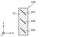
図5は、本実施の形態に係る入射部10Eの構成の第一例を示す模式図である。
Figure 5 is a schematic diagram showing a first example of the configuration of the
図5に示される入射部10Eは、偏向素子30A、30Bおよび30Cと、透明部材15とを備える。
The
透明部材15は、その内部に偏向素子30A、30Bおよび30Cを有する。透明部材15は、偏向素子30A等が、光L1、L1BおよびL1Cを適切な角度で反射する位置及び姿勢をとるように偏向素子30A等を支持している。
The
偏向素子30A、30Bおよび30Cは、透明部材15の内部に埋設されているともいえる。また、入射部10Eの内部のうち、偏向素子30A、30Bおよび30Cを除く空間は、透明部材15で満たされているともいえる。
It can be said that the
このような構成をとることで、入射部10Eは、透明部材15によって、より高い精度で適切な位置および姿勢に支持された偏向素子30A等を用いて、光L1、L1BおよびL1Cを導光することができ、導光する光の光路をより適切に維持することができる。この効果は、振動がある環境に導光板10が配置される場合には、特に顕著である。
By adopting such a configuration, the
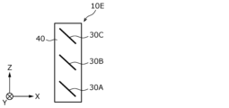
図6は、本実施の形態に係る入射部10Eの構成の第二例を示す模式図である。図6に示される入射部10Eは、入射部10Eの、図5とは異なる構成を示している。
Figure 6 is a schematic diagram showing a second example of the configuration of the
図6に示される入射部10Eは、偏向素子30A、30Bおよび30Cと、支持部材(不図示)を備える。
The
入射部10Eは中空である。偏向素子30A、30Bおよび30Cは、入射部10Eの内部の空間40に、光L1、L1BおよびL1Cを適切な角度で反射する位置及び姿勢をとるように適切な支持部材によって支持されている。
The
このような構成をとることで、入射部10Eは、適切な位置および姿勢に支持された偏向素子30A等を用いて、光L1、L1BおよびL1Cを導光することができる。また、重量の増加を抑制できる利点がある。
By adopting such a configuration, the
(実施の形態の変形例)
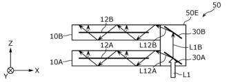
図7は、本変形例に係る導光板の構成の第一例として、導光板50の構成を示す模式図である。
(Modification of the embodiment)
FIG. 7 is a schematic diagram showing the configuration of a
図7に示される導光板50は、入射部50Eと、導光体10Aおよび10Bとを備える。
The
入射部50Eは、偏向素子30Aおよび30Bを有する。
The
導光板50つまり入射部50Eに入射される光L1は、Y軸プラス方向およびZ軸プラス方向に進行する光であり、導光板50のZ軸マイナス方向側の面から導光板50に入射する。
Light L1 that is incident on the
偏向素子30Aは、入射光である光L1に含まれる所定の波長成分(第一波長成分ともいう)の光を選択的に偏向することで導光体10Aに入射させる偏向素子である。偏向素子30Aは、第一偏向素子に相当する。偏向素子30Aは、上記実施の形態における偏向素子30Aと同様である。
偏向素子30Bは、入射光である光L1に含まれる所定の波長成分(第二波長成分ともいう)の光を選択的に偏向することで導光体10Bに入射させる偏向素子である。偏向素子30Bは、第二偏向素子に相当する。偏向素子30Bは、上記実施の形態における偏向素子30Bと同様である。
このように、導光体10Aは、導光体10Aにより導光された光を、光L1が入射された面(つまりZ軸マイナス方向側の面)と反対側の面(つまりZ軸プラス方向側の面)から出射する。また、導光体10Bは、導光体10Bにより導光された光を、光L1が入射された面と反対側の面から出射する。
In this way,
入射する光L1は、例えば、2つの色(例えば、赤色と緑色)に相当する波長成分を有する光である。この場合、偏向素子30Aは、例えば、赤色に相当する波長成分の光を偏向することで導光体10Aに入射させるとともに、緑色に相当する波長成分の光を透過させる。偏向素子30Bは、例えば、緑色に相当する波長成分の光を偏向することで導光体10Bに入射させる。このようにすることで、導光板50は、赤色および緑色の光による表示画像を表示させることができる。なお、上記の赤色と緑色とを入れ替えても同様の説明が成立する。また、上記の2つの色は、赤色と青色としてもよいし、緑色と青色としてもよい。
The incident light L1 is, for example, light having wavelength components corresponding to two colors (e.g., red and green). In this case, the
また、入射する光L1は、例えば、3つの色(例えば、赤色と緑色と青色)に相当する波長成分を有する光であってもよい。 In addition, the incident light L1 may be, for example, light having wavelength components corresponding to three colors (e.g., red, green, and blue).
この場合、偏向素子30Aは、例えば、赤色に相当する波長成分の光を偏向することで導光体10Aに入射させるとともに、緑色と青色とに相当する波長成分の光を透過させる。偏向素子30Bは、例えば、緑色と青色とに相当する波長成分の光を偏向することで導光体10Bに入射させる。このようにすることで、赤色、緑色および青色の光による表示画像を表示させることができる。
In this case, the
また、偏向素子30Aは、例えば、青色に相当する波長成分の光を偏向することで導光体10Aに入射させるとともに、緑色と赤色とに相当する波長成分の光を透過させてもよい。この場合、偏向素子30Bは、例えば、緑色と赤色とに相当する波長成分の光を偏向することで導光体10Bに入射させる。このようにすることで、赤色、緑色および青色の光による表示画像を表示させることができる。
Furthermore, the
図8は、本変形例に係る導光板の構成の第二例として、導光板51の構成を示す模式図である。
Figure 8 is a schematic diagram showing the configuration of
図8に示される導光板51は、入射部50Fと、導光体10Aおよび10Bとを備える。
The
入射部50Fは、偏向素子30Dおよび30Eを有する。
The
導光板51つまり入射部50Fに入射される光L1は、Y軸プラス方向およびZ軸マイナス方向に進行する光であり、導光板51のZ軸プラス方向側の面から導光板51に入射する。
Light L1 that is incident on the
偏向素子30Dは、入射光である光L1に含まれる所定の波長成分(第一波長成分ともいう)の光を導光体10Aに入射させる偏向素子である。偏向素子30Dは、第一偏向素子に相当する。偏向素子30Dは、上記の導光板50が有する偏向素子30Aと同じ構成を有するが、その位置および姿勢が異なり得る。
偏向素子30Eは、入射光である光L1に含まれる所定の波長成分(第二波長成分ともいう)の光を導光体10Bに入射させる偏向素子である。偏向素子30Eは、第二偏向素子に相当する。偏向素子30Eは、上記の導光板50が有する偏向素子30Bと同じ構成を有するが、その位置および姿勢が異なり得る。
The
この構成では、導光体10Aは、導光体10Aにより導光された光を、光L1が入射された面(つまりZ軸プラス方向側の面)と同じ側の面(つまりZ軸プラス方向側の面)から出射する。また、導光体10Bは、導光体10Bにより導光された光を、光L1が入射された面と同じ側の面から出射する。
In this configuration,
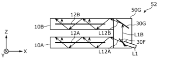
図9は、本変形例に係る導光板の構成の第三例として、導光板52の構成を示す模式図である。
Figure 9 is a schematic diagram showing the configuration of
図9に示される導光板52は、入射部50Gと、導光体10Aおよび10Bとを備える。
The
入射部50Gは、偏向素子30Fおよび30Gを有する。
The
導光板52つまり入射部50Gに入射される光L1は、X軸マイナス方向およびZ軸プラス方向に進行する光であり、導光板52のX軸プラス方向側の面から導光板52に入射する。
Light L1 that is incident on the
偏向素子30Fは、入射光である光L1に含まれる所定の波長成分(第一波長成分ともいう)の光を導光体10Aに入射させる偏向素子である。偏向素子30Fは、上記所定の波長成分の光を透過することで導光体10Aに入射させ、上記所定の波長成分以外の光を偏向することで、偏向素子30Gに向けて進行させる。偏向素子30Fは、第一偏向素子に相当する。偏向素子30Fは、上記の導光板50が有する偏向素子30Aと同じ構成を有するが、その位置および姿勢が異なり得る。
偏向素子30Gは、入射光である光L1に含まれる所定の波長成分(第二波長成分ともいう)の光を導光体10Bに入射させる偏向素子である。偏向素子30Gは、第二偏向素子に相当する。偏向素子30Gは、上記の導光板50が有する偏向素子30Bと同じ構成を有するが、その位置および姿勢が異なり得る。
The
この構成では、導光体10Aは、導光体10Aにより導光された光を、光L1が入射された面(つまりX軸プラス方向側の面)と同じ側でも反対側でもない面(つまりZ軸プラス方向側の面)から出射する。また、導光体10Bは、導光体10Bにより導光された光を、光L1が入射された面と同じ側でも反対側でもない面から出射する。
In this configuration,
以上のように、上記実施の形態または変形例における導光板は、入射光に含まれる2つの波長成分の光それぞれを、偏向素子によって選択的に偏向することで2つの導光体それぞれに入射させるので、光の強度の低下、および、迷光の発生を抑制することができる。このように、導光板は、表示される画像の品質の低下を抑制することができる。 As described above, the light guide plate in the above embodiment or modified example selectively deflects the two wavelength components contained in the incident light with a deflection element, causing the light to enter each of the two light guides, thereby suppressing a decrease in light intensity and the occurrence of stray light. In this way, the light guide plate can suppress a decrease in the quality of the displayed image.
また、導光板は、入射光に含まれる2つの波長成分の光それぞれを偏向素子による反射を用いて2つの導光体それぞれに入射させるので、光の強度の低下、および、迷光の発生を抑制することができる。このように、導光板は、表示される画像の品質の低下を抑制することができる。 In addition, the light guide plate allows each of the two wavelength components contained in the incident light to be incident on each of the two light guides by using reflection from the deflection element, thereby suppressing a decrease in light intensity and the occurrence of stray light. In this way, the light guide plate can suppress a decrease in the quality of the displayed image.
また、導光板は、赤色に相当する波長成分を第一導光体に入射させるとともに、緑色および青色に相当する波長成分を第二導光体に入射させることで、赤色、緑色および青色の3つの波長成分を含む光を導光し、上記3つの波長成分を含むフルカラーの表示画像を表示することに寄与する。よって、導光板は、フルカラーの表示画像の品質の低下をより一層抑制することができる。 The light guide plate also guides light containing the three wavelength components of red, green, and blue by allowing the wavelength component corresponding to red to enter the first light guide and the wavelength components corresponding to green and blue to enter the second light guide, thereby contributing to displaying a full-color display image containing the above three wavelength components. Therefore, the light guide plate can further suppress deterioration in the quality of the full-color display image.
また、導光板は、透明部材が光を透過させながら偏向素子を支持するので、偏向素子の位置をより高い精度で適切な位置に維持することができ、その結果、偏向素子が偏向した光の光路をより適切に維持することができる。この効果は、振動がある環境に導光板が配置される場合には、特に顕著である。これにより、偏向素子の位置が変化することによる光の光路のずれを抑制し、表示される画像の品質の低下を抑制することができる。よって、導光板は、表示される画像の品質の低下をより一層抑制することができる。 In addition, because the light guide plate supports the deflection element while allowing light to pass through the transparent member, the position of the deflection element can be maintained in an appropriate position with greater precision, and as a result, the optical path of the light deflected by the deflection element can be more appropriately maintained. This effect is particularly noticeable when the light guide plate is placed in an environment where vibrations are present. This makes it possible to suppress deviations in the optical path of light caused by changes in the position of the deflection element, and suppress deterioration in the quality of the displayed image. Therefore, the light guide plate can further suppress deterioration in the quality of the displayed image.
また、導光板は、入射光に含まれる3つの波長成分の光それぞれを、偏向素子によって選択的に偏向することで3つの導光体それぞれに入射させるので、光の強度の低下、および、迷光の発生を抑制することができる。このように、導光板は、表示される画像の品質の低下を抑制することができる。 In addition, the light guide plate selectively deflects each of the three wavelength components contained in the incident light using a deflection element, causing the light to enter each of the three light guides, thereby suppressing a decrease in light intensity and the occurrence of stray light. In this way, the light guide plate can suppress a decrease in the quality of the displayed image.
また、導光板は、入射光に含まれる3つの波長成分の光それぞれを偏向素子による反射を用いて3つの導光体それぞれに入射させるので、光の強度の低下、および、迷光の発生を抑制することができる。このように、導光板は、表示される画像の品質の低下を抑制することができる。 In addition, the light guide plate allows each of the three wavelength components contained in the incident light to be incident on each of the three light guides by using reflection from the deflection element, thereby suppressing a decrease in light intensity and the occurrence of stray light. In this way, the light guide plate can suppress a decrease in the quality of the displayed image.
また、導光板は、入射光が入射する面と反対側の面に光を出射するので、入射光を出射する機材(例えば画像生成装置に相当)と、出射した光を受ける機材(例えばウィンドシールドに相当)とが、当該導光板に対して反対側に存在する場合に、両機材の間で適切に光を導光することができる。よって、導光板は、光を適切に導光しながら、表示される画像の品質の低下を抑制することができる。 In addition, since the light guide plate emits light to the surface opposite to the surface on which the incident light is incident, when a device that emits the incident light (e.g., an image generating device) and a device that receives the emitted light (e.g., a windshield) are located on opposite sides of the light guide plate, the light can be appropriately guided between the two devices. Therefore, the light guide plate can appropriately guide light while suppressing deterioration in the quality of the displayed image.
また、導光板は、入射光が入射する面と同じ側の面に光を出射するので、入射光を出射する機材(例えば画像生成装置に相当)と、出射した光を受ける機材(例えばウィンドシールドに相当)とが、当該導光板に対して同じ側に存在する場合に、両機材の間で適切に光を導光することができる。よって、導光板は、光を適切に導光しながら、表示される画像の品質の低下を抑制することができる。 In addition, since the light guide plate emits light to the same surface as the surface on which the incident light is incident, when a device that emits the incident light (e.g., an image generating device) and a device that receives the emitted light (e.g., a windshield) are on the same side of the light guide plate, the light can be appropriately guided between the two devices. Therefore, the light guide plate can appropriately guide light while suppressing deterioration in the quality of the displayed image.
また、表示装置は、導光板を用いて、表示される画像の品質の低下を抑制することができる。 In addition, the display device can use a light guide plate to suppress deterioration in the quality of the displayed image.
以上、一つまたは複数の態様に係る導光板などについて、実施の形態に基づいて説明したが、本発明は、この実施の形態に限定されるものではない。本発明の趣旨を逸脱しない限り、当業者が思いつく各種変形を本実施の形態に施したものや、異なる実施の形態における構成要素を組み合わせて構築される形態も、一つまたは複数の態様の範囲内に含まれてもよい。 The light guide plate and the like according to one or more aspects have been described above based on the embodiment, but the present invention is not limited to this embodiment. As long as it does not deviate from the spirit of the present invention, various modifications conceivable by a person skilled in the art to this embodiment and forms constructed by combining components of different embodiments may also be included within the scope of one or more aspects.
本発明は、車両のヘッドアップディスプレイ装置等に利用可能である。 The present invention can be used in vehicle head-up display devices, etc.
1 表示装置
5 車両
10、50、51、52、90 導光板
10A、10B、10C、90A、90B、90C 導光体
10E、50E、50F、50G 入射部
12A、12B、12C、13A、13B、13C、91A、91B、91C ホログラム素子
14 虚像
15 透明部材
17 画像生成装置
20 ウィンドシールド
30A、30B、30C、30D、30E、30F、30G 偏向素子
40 空間
L1、L1B、L1C、L12A、L12B、L12C、L23A、L23B、L23C、L3、L3A、L3B、L3C、L5、LA、LB、LC 光
U ユーザ
1
Claims (8)
前記導光板は、画像を示す光を生成して前記導光板に入射させる画像生成装置を備えるヘッドアップディスプレイに設けられ、
第一導光体と、
第二導光体と、
入射光に含まれる第一波長成分の光を選択的に偏向することで前記第一導光体に入射させる第一偏向素子と、
前記入射光に含まれる第二波長成分の光を選択的に偏向することで前記第二導光体に入射させる第二偏向素子と、
前記第一偏向素子と前記第二偏向素子とを一つの透明部材内に有する入射部とを備え、
前記入射部は、前記第一導光体及び前記第二導光体とは別体として設けられ、
前記第一偏向素子と前記第二偏向素子とは、前記入射光の光を偏向することで入射させるそれぞれの導光体に対して、傾斜角を有するように設けられており、
前記第一導光体と前記第二導光体とは、平行に配置されており、前記第一導光体または前記第二導光体の法線方向から見て重なっており、
前記入射部内において前記光が進行する方向は、前記第一導光体が配置された平面、および、前記第二導光体が配置された平面のそれぞれに交差する方向である
導光板。 A light guide plate,
The light guide plate is provided in a head-up display including an image generating device that generates light representing an image and causes the light to enter the light guide plate,
A first light guide;
A second light guide;
a first deflection element that selectively deflects light of a first wavelength component included in the incident light to cause the light to enter the first light guiding body;
a second deflection element that selectively deflects light of a second wavelength component included in the incident light to cause the light to be incident on the second light guiding body;
an entrance portion having the first deflection element and the second deflection element in one transparent member,
the incident portion is provided separately from the first light guide and the second light guide,
the first deflection element and the second deflection element are provided to have an inclination angle with respect to each of the light guides that deflect the incident light and make the light incident thereto;
the first light guide and the second light guide are arranged in parallel and overlap each other when viewed from a normal direction of the first light guide or the second light guide,
The direction in which the light travels within the incident portion is a direction intersecting both a plane in which the first light guide is disposed and a plane in which the second light guide is disposed.
Light guide plate.
前記第二偏向素子は、前記入射光に含まれる前記第二波長成分の光を選択的に反射することで前記第二導光体に入射させ、前記入射光に含まれる前記第二波長成分以外の光を透過する
請求項1に記載の導光板。 the first deflection element selectively reflects light of the first wavelength component contained in the incident light to cause it to enter the first light guiding body and transmits light other than the first wavelength component contained in the incident light;
The light guide plate according to claim 1 , wherein the second deflection element selectively reflects light of the second wavelength component contained in the incident light to cause it to enter the second light guide and transmits light other than the second wavelength component contained in the incident light.
前記第二波長成分は、緑色に相当する波長成分と青色に相当する波長成分とである
請求項1または2に記載の導光板。 the first wavelength component is a wavelength component corresponding to red,
The light guide plate according to claim 1 , wherein the second wavelength component is a wavelength component corresponding to green and a wavelength component corresponding to blue.
前記第一偏向素子と前記第二偏向素子との、位置及び姿勢を支持する支持部材を備える
請求項1~3のいずれか1項に記載の導光板。 The light guide plate further comprises:
The light guide plate according to claim 1 , further comprising a support member that supports positions and attitudes of the first deflection element and the second deflection element.
第三導光体と、
前記入射光に含まれる第三波長成分の光を前記第三導光体に入射させる第三偏向素子とを備える
請求項1~4のいずれか1項に記載の導光板。 The light guide plate further comprises:
A third light guiding body;
The light guide plate according to claim 1 , further comprising: a third deflector element that causes light of a third wavelength component contained in the incident light to enter the third light guiding body.
請求項5に記載の導光板。 The light guide plate according to claim 5 , wherein the third deflection element selectively deflects light of the third wavelength component contained in the incident light to cause it to be incident on the third light guiding body.
前記第二導光体は、前記第二導光体により導光された光を前記入射光が入射された面と反対側の面から出射する
請求項1~6のいずれか1項に記載の導光板。 the first light guide emits the light guided by the first light guide from a surface opposite to a surface into which the incident light is incident,
The light guide plate according to claim 1 , wherein the second light guide emits the light guided by the second light guide from a surface opposite to a surface into which the incident light is incident.
前記第二導光体は、前記第二導光体により導光された光を前記入射光が入射された面と同じ側の面から出射する
請求項1~6のいずれか1項に記載の導光板。 the first light guide emits the light guided by the first light guide from a surface on the same side as a surface into which the incident light is incident,
The light guide plate according to claim 1 , wherein the second light guide emits the light guided by the second light guide from a surface on the same side as a surface into which the incident light is incident.
Priority Applications (3)
| Application Number | Priority Date | Filing Date | Title |
|---|---|---|---|
| JP2021058956A JP7651237B2 (en) | 2021-03-31 | 2021-03-31 | Light guide plate |
| PCT/JP2022/000017 WO2022209106A1 (en) | 2021-03-31 | 2022-01-04 | Light guide plate, light guide plate unit, and display device |
| US18/373,753 US12596220B2 (en) | 2021-03-31 | 2023-09-27 | Light guide plate, light guide plate unit, and display device |
Applications Claiming Priority (1)
| Application Number | Priority Date | Filing Date | Title |
|---|---|---|---|
| JP2021058956A JP7651237B2 (en) | 2021-03-31 | 2021-03-31 | Light guide plate |
Publications (2)
| Publication Number | Publication Date |
|---|---|
| JP2022155627A JP2022155627A (en) | 2022-10-14 |
| JP7651237B2 true JP7651237B2 (en) | 2025-03-26 |
Family
ID=83558611
Family Applications (1)
| Application Number | Title | Priority Date | Filing Date |
|---|---|---|---|
| JP2021058956A Active JP7651237B2 (en) | 2021-03-31 | 2021-03-31 | Light guide plate |
Country Status (1)
| Country | Link |
|---|---|
| JP (1) | JP7651237B2 (en) |
Citations (5)
| Publication number | Priority date | Publication date | Assignee | Title |
|---|---|---|---|---|
| JP2019510995A (en) | 2016-01-16 | 2019-04-18 | レイア、インコーポレイテッドLeia Inc. | Multi-beam grating based head-up display |
| JP2019522230A (en) | 2016-05-12 | 2019-08-08 | マジック リープ, インコーポレイテッドMagic Leap,Inc. | Distributed light manipulation for imaging waveguides |
| JP2019184920A (en) | 2018-04-13 | 2019-10-24 | 株式会社デンソー | Head-up display device |
| WO2020080117A1 (en) | 2018-10-15 | 2020-04-23 | ソニー株式会社 | Image display device, head-mounted display, method for manufacturing image display device, and method for adjusting image display device |
| JP2020519962A (en) | 2017-05-16 | 2020-07-02 | マジック リープ, インコーポレイテッドMagic Leap,Inc. | Systems and methods for mixed reality |
Family Cites Families (2)
| Publication number | Priority date | Publication date | Assignee | Title |
|---|---|---|---|---|
| JP2774398B2 (en) * | 1991-09-17 | 1998-07-09 | 富士通株式会社 | Hologram making device |
| JPH05201272A (en) * | 1992-01-24 | 1993-08-10 | Asahi Glass Co Ltd | Head-up display for vehicle |
-
2021
- 2021-03-31 JP JP2021058956A patent/JP7651237B2/en active Active
Patent Citations (5)
| Publication number | Priority date | Publication date | Assignee | Title |
|---|---|---|---|---|
| JP2019510995A (en) | 2016-01-16 | 2019-04-18 | レイア、インコーポレイテッドLeia Inc. | Multi-beam grating based head-up display |
| JP2019522230A (en) | 2016-05-12 | 2019-08-08 | マジック リープ, インコーポレイテッドMagic Leap,Inc. | Distributed light manipulation for imaging waveguides |
| JP2020519962A (en) | 2017-05-16 | 2020-07-02 | マジック リープ, インコーポレイテッドMagic Leap,Inc. | Systems and methods for mixed reality |
| JP2019184920A (en) | 2018-04-13 | 2019-10-24 | 株式会社デンソー | Head-up display device |
| WO2020080117A1 (en) | 2018-10-15 | 2020-04-23 | ソニー株式会社 | Image display device, head-mounted display, method for manufacturing image display device, and method for adjusting image display device |
Also Published As
| Publication number | Publication date |
|---|---|
| JP2022155627A (en) | 2022-10-14 |
Similar Documents
| Publication | Publication Date | Title |
|---|---|---|
| US11513473B2 (en) | Waveguide, waveguide manufacturing apparatus, waveguide manufacturing method, and video display device using the same | |
| JP5316391B2 (en) | Image display device and head-mounted display | |
| JP6394393B2 (en) | Image display device, image generation device, and transmissive spatial light modulation device | |
| JP6035793B2 (en) | Image display device and image generation device | |
| JP4674634B2 (en) | Head-mounted display | |
| JP5732808B2 (en) | Virtual image display device | |
| US20210033774A1 (en) | Image display device | |
| JP4858512B2 (en) | Head-mounted display | |
| JP2010122478A (en) | Image display device and head mount display | |
| JP2008083539A (en) | Optical system for light beam transfer, and retinal scanning display using the same | |
| JP2010044172A (en) | Virtual image display device | |
| JP2012163657A (en) | Virtual image display device | |
| JP2013109203A (en) | Light beam expanding device, image display device, and optical device | |
| JP6565496B2 (en) | Light guide device and virtual image display device | |
| US20250053008A1 (en) | Optical waveguide with integrated optical elements | |
| JP5035465B2 (en) | Head-mounted display | |
| WO2020179470A1 (en) | Image display device | |
| JP7651237B2 (en) | Light guide plate | |
| US20210382309A1 (en) | Image display device | |
| US12468081B2 (en) | Optical element and virtual image display device | |
| WO2020241218A1 (en) | Projection device and head-up display | |
| US11754839B2 (en) | Display module and display device | |
| US12596220B2 (en) | Light guide plate, light guide plate unit, and display device | |
| US20250102806A1 (en) | Virtual image display device and optical unit | |
| US12619083B2 (en) | Virtual-image display device and optical unit |
Legal Events
| Date | Code | Title | Description |
|---|---|---|---|
| A621 | Written request for application examination |
Free format text: JAPANESE INTERMEDIATE CODE: A621 Effective date: 20231109 |
|
| A711 | Notification of change in applicant |
Free format text: JAPANESE INTERMEDIATE CODE: A711 Effective date: 20240304 |
|
| A131 | Notification of reasons for refusal |
Free format text: JAPANESE INTERMEDIATE CODE: A131 Effective date: 20240521 |
|
| A521 | Request for written amendment filed |
Free format text: JAPANESE INTERMEDIATE CODE: A523 Effective date: 20240722 |
|
| A131 | Notification of reasons for refusal |
Free format text: JAPANESE INTERMEDIATE CODE: A131 Effective date: 20240910 |
|
| A521 | Request for written amendment filed |
Free format text: JAPANESE INTERMEDIATE CODE: A523 Effective date: 20241106 |
|
| A131 | Notification of reasons for refusal |
Free format text: JAPANESE INTERMEDIATE CODE: A131 Effective date: 20241224 |
|
| A521 | Request for written amendment filed |
Free format text: JAPANESE INTERMEDIATE CODE: A523 Effective date: 20250203 |
|
| TRDD | Decision of grant or rejection written | ||
| A01 | Written decision to grant a patent or to grant a registration (utility model) |
Free format text: JAPANESE INTERMEDIATE CODE: A01 Effective date: 20250212 |
|
| A61 | First payment of annual fees (during grant procedure) |
Free format text: JAPANESE INTERMEDIATE CODE: A61 Effective date: 20250311 |
|
| R150 | Certificate of patent or registration of utility model |
Ref document number: 7651237 Country of ref document: JP Free format text: JAPANESE INTERMEDIATE CODE: R150 |