JP7650737B2 - shutter - Google Patents
shutter Download PDFInfo
- Publication number
- JP7650737B2 JP7650737B2 JP2021108433A JP2021108433A JP7650737B2 JP 7650737 B2 JP7650737 B2 JP 7650737B2 JP 2021108433 A JP2021108433 A JP 2021108433A JP 2021108433 A JP2021108433 A JP 2021108433A JP 7650737 B2 JP7650737 B2 JP 7650737B2
- Authority
- JP
- Japan
- Prior art keywords
- shutter
- winding shaft
- motor
- unit
- control unit
- Prior art date
- Legal status (The legal status is an assumption and is not a legal conclusion. Google has not performed a legal analysis and makes no representation as to the accuracy of the status listed.)
- Active
Links
- 238000004804 winding Methods 0.000 claims description 119
- 238000004891 communication Methods 0.000 claims description 39
- 238000003780 insertion Methods 0.000 claims description 15
- 230000037431 insertion Effects 0.000 claims description 15
- 230000004308 accommodation Effects 0.000 description 6
- 238000006073 displacement reaction Methods 0.000 description 4
- 230000002452 interceptive effect Effects 0.000 description 4
- 230000000903 blocking effect Effects 0.000 description 3
- 230000005611 electricity Effects 0.000 description 3
- 239000000463 material Substances 0.000 description 2
- 238000005516 engineering process Methods 0.000 description 1
- 238000001125 extrusion Methods 0.000 description 1
- 230000010365 information processing Effects 0.000 description 1
- 238000007689 inspection Methods 0.000 description 1
- 238000012423 maintenance Methods 0.000 description 1
- 239000011347 resin Substances 0.000 description 1
- 229920005989 resin Polymers 0.000 description 1
Images


Landscapes
- Operating, Guiding And Securing Of Roll- Type Closing Members (AREA)
- Power-Operated Mechanisms For Wings (AREA)
Description
本発明は、シャッターカーテンが連結された巻取軸をモータにより回転するシャッターに関する。 The present invention relates to a shutter in which a motor rotates a winding shaft to which a shutter curtain is connected.
電動式のシャッターでは、制御部によりモータの駆動を制御して、モータによりシャッターケース内の巻取軸を回転させる。巻取軸の回転に伴い、シャッターケース内で、巻取軸へのシャッターカーテンの巻き取りと巻取軸からのシャッターカーテンの繰り出しとが行われる。また、リモートコントロール式のシャッターでは、通信部がリモートコントローラと通信し、通信部の受信データに基づいて、制御部が巻取軸を回転させる。このようなシャッターの通信部は、シャッターカーテンとの干渉を回避して、シャッターケース内に設けることが求められる。これに対し、従来、筐体の少なくとも一部を巻取体の内部に配置し、無線モジュールである受信装置を筐体に取り付けたシャッタ装置が知られている(特許文献1参照)。 In an electric shutter, a control unit controls the drive of a motor, which rotates a winding shaft inside the shutter case. As the winding shaft rotates, the shutter curtain is wound onto the winding shaft and unwound from the winding shaft inside the shutter case. In a remote-controlled shutter, a communication unit communicates with a remote controller, and the control unit rotates the winding shaft based on data received from the communication unit. The communication unit of such a shutter must be located inside the shutter case, avoiding interference with the shutter curtain. In response to this, a shutter device has been known in the past in which at least a portion of the housing is located inside the winding body and a receiving device, which is a wireless module, is attached to the housing (see Patent Document 1).
特許文献1に記載された従来のシャッタ装置では、筐体は、円筒状の本体部と、本体部の一方側の開口を閉塞する閉塞部材を有している。閉塞部材には貫通孔が形成され、受信装置が閉塞部材の貫通孔内に樹脂クリップで取り付けられる。そのため、受信装置をシャッタ装置に設置するための構成が複雑になり、受信装置の設置に要する部品の数も増加する虞がある。また、従来のシャッタ装置では、受信装置の蓋部に、ステータスランプと送信機の登録用のスイッチが設けられている。ところが、受信装置の蓋部が筐体の本体部の内部に位置するため、ステータスランプの確認とスイッチの操作とが行い難い。この従来のシャッタ装置のように、駆動モータの制御部の操作に用いられるスイッチとシャッタ装置の状態を確認するためのランプのうちの少なくとも一方を受信装置の蓋部に設けたときには、駆動モータの制御部の操作とシャッタ装置の状態の確認のうちの少なくとも一方が行い難くなる。
In the conventional shutter device described in
本発明は、前記従来の問題に鑑みなされたもので、その目的は、シャッターの通信部をシャッターカーテンと干渉させずにシャッターケース内に簡便に設けるとともに、モータの制御部の操作とシャッターの状態の確認のうちの少なくとも一方を容易に行うことである。 The present invention was developed in consideration of the above-mentioned problems with the conventional technology, and its purpose is to easily install the shutter's communication unit inside the shutter case without interfering with the shutter curtain, and to easily perform at least one of operating the motor's control unit and checking the shutter's status.
本発明は、
シャッターカーテンが連結された巻取軸と、
前記巻取軸及び前記巻取軸に巻き取られた前記シャッターカーテンを収容するシャッターケースと、
前記シャッターケース内で前記シャッターカーテンの側方に配置されたシャッターガイドと、
前記巻取軸を回転させるモータと、
前記モータを制御する制御部と、
前記制御部と接続して外部機器と通信する通信部と、
前記制御部の操作に用いられる操作部とシャッターの状態を表示する表示部のうちの少なくとも一方と、を備え、
前記シャッターケースは、前記巻取軸の室外側に位置する前面板を有し、
前記シャッターガイドは、前記前面板と対向して配置されて、前記通信部を収容する収容部を有し、
前記操作部と前記表示部のうちの少なくとも一方は、前記収容部の下部に設けられ、
前記モータと前記制御部は、前記巻取軸の内部に収容され、
前記シャッターカーテンの側方で前記収容部から前記巻取軸に向かって延び、前記通信部と前記制御部を接続するケーブルを備えたシャッターである。
The present invention relates to
A winding shaft to which the shutter curtain is connected;
A shutter case that accommodates the winding shaft and the shutter curtain wound around the winding shaft;
A shutter guide disposed on a side of the shutter curtain in the shutter case;
A motor that rotates the winding shaft;
A control unit for controlling the motor;
a communication unit connected to the control unit and configured to communicate with an external device;
At least one of an operation unit used to operate the control unit and a display unit that displays a state of the shutter,
The shutter case has a front panel located on the outdoor side of the winding shaft,
the shutter guide has a housing portion disposed opposite the front plate and housing the communication portion,
At least one of the operation unit and the display unit is provided at a lower portion of the storage unit ,
The motor and the control unit are housed inside the winding shaft,
The shutter is provided with a cable that extends from the storage section toward the winding shaft on the side of the shutter curtain and connects the communication section and the control section .
本発明によれば、シャッターの通信部をシャッターカーテンと干渉させずにシャッターケース内に簡便に設けられるとともに、モータの制御部の操作とシャッターの状態の確認のうちの少なくとも一方を容易に行うことができる。 According to the present invention, the shutter's communication unit can be easily installed inside the shutter case without interfering with the shutter curtain, and at least one of operating the motor's control unit and checking the shutter's status can be easily performed.
本発明のシャッターの一実施形態について、図面を参照して説明する。
本実施形態のシャッターは、電動式のシャッター装置(電動シャッター)であり、電気を動力として電力により駆動される。以下では、スライド式の障子を備えた建具を例にとり、建具に設けられた建物用(建具用)のシャッターについて説明する。シャッター及び建具は、建物の壁部に設置されて、建物の室内(屋内)と室外(屋外)の間に配置される。
An embodiment of a shutter of the present invention will be described with reference to the drawings.
The shutter of this embodiment is an electric shutter device (electric shutter), and is driven by electricity. Below, a building shutter (for fittings) provided on fittings will be described using a fitting with a sliding shoji screen as an example. The shutter and fittings are installed on the wall of a building and are disposed between the interior (indoors) and exterior (outdoors) of the building.
図1は、本実施形態のシャッター1を示す正面図であり、閉じた状態のシャッター1を室外側からみて示している。
図示のように、シャッター1は、建具の上部に設置されるシャッターケース2と、建具の室外側で移動可能(昇降可能)なシャッターカーテン3と、一対のガイドレール4を備えている。シャッターケース2は、箱状のケーシング(シャッターボックス)である。シャッターカーテン3は、上下方向に移動して開閉する。
FIG. 1 is a front view showing a
As shown in the figure, the
なお、建物に設けたシャッター1を正面からみたときに、上下となる方向が上下方向であり、左右となる方向が左右方向である。図1では、上下方向は鉛直方向であり、左右方向は水平方向である。室内外方向は、建物に設けたシャッター1における室内外方向(屋内外方向)である。また、室内外方向は、建物に設けたシャッター1を正面からみたときに、前後となる方向であり、図1では、左右方向に直交する水平方向である。このように、シャッター1に関する方向は、建物に設けた状態での方向で特定する。また、シャッター1に関して室内側、室外側とは、建物に設けた状態での室内側、室外側である。
When the
シャッターカーテン3は、互いに回動可能に連結された複数のスラット3Aと、下端部に設けられた座板3Bを有している。複数のスラット3Aは、それぞれ左右方向に延び、上下方向に順に並べて、互いに平行に配置されている。座板3Bは、最下部のスラット3Aの下側に配置されて、最下部のスラット3Aに回動可能に取り付けられている。シャッターカーテン3は、左右のガイドレール4に移動可能に連結されて、左右のガイドレール4の間で上下方向に移動する。ガイドレール4は、シャッターカーテン3の左右の側部に連結されている。
The
ガイドレール4は、シャッターカーテン3の開閉時(昇降時)に、シャッターカーテン3の左右の側部を上下方向にガイドする。シャッターカーテン3を閉めるときに、シャッターカーテン3は、シャッターケース2から繰り出されて、下方に移動する。また、シャッターカーテン3を開けるときには、シャッターカーテン3は、シャッターケース2に向かって巻き上げられて、上方に移動し、シャッターケース2の内部に収容される。
The guide rails 4 guide the left and right sides of the
図2は、本実施形態の建具5に設けられたシャッター1を示す縦断面部であり、建物6の壁部6Aに設置された建具5及びシャッター1を上下方向に切断して示している。図3は、本実施形態の建具5及びシャッター1を分解して示す斜視図である。
図示のように、建具5は、建物6の開口部に設置される引き違い窓であり、スライド式の2つの障子5A、5B(第1障子5A、第2障子5B)及び1つの網戸5Cと、障子5A、5B及び網戸5Cを囲む枠体10を備えている。
Fig. 2 is a vertical cross-sectional view showing the
As shown in the figure, the
障子5A、5Bは、スライドにより移動するパネル状の可動障子(パネル体)であり、枠体10の開口部11に移動可能(スライド可能)に配置されている。障子5A、5Bは、枠体10の開口部11内で、左右方向にスライドして引き違い状に移動する。引き違い障子である障子5A、5Bにより、枠体10の開口部11が開閉される。第1障子5Aは、室内側に位置する室内側障子であり、第2障子5Bは、室外側に位置する室外側障子である。網戸5Cは、障子5A、5Bの室外側で、左右方向にスライドして移動する。
The
枠体10は、方形状の開口枠(窓枠)であり、建物6の方形状の開口部に設置される。また、枠体10は、互いに組み合わされた4つの枠12~14(上枠12、下枠13、一対の縦枠14)を有し、4つの枠12~14により、方形状の開口部11を形成している。枠12~14は、枠体10を構成する枠材であり、例えば、押出成形により形成された形材からなる。上枠12と下枠13は、枠体10の上下の横枠であり、枠体10の上部と下部で左右方向(横方向)に延びる。一対の縦枠14は、枠体10の左右の側部に位置する側枠であり、枠体10の側部で上下方向(縦方向)に延びる。上枠12、下枠13、及び、左右の縦枠14が接続されて、枠12~14が枠組みされている。
The
一対の縦枠14が上枠12よりも上方に突出して、上面板15が一対の縦枠14の上端部に架け渡されている。上面板15は、上枠12の上方に配置されて、一対の縦枠14の上端部に取り付けられ、上枠12と上下方向において対向している。枠体10の上枠12の上側には、シャッターケース2を収容する収容空間16が区画されている。収容空間16は、上枠12、一対の縦枠14の上枠12よりも上側の部分、及び、上面板15により囲まれて、枠体10の開口部11の上側に位置している。
A pair of
シャッターケース2は、収容空間16に室外側から収容されて、収容空間16内に取り付けられ、枠体10の上部(枠体10の開口部11の上側)に設けられる。ガイドレール4は、一対の縦枠14の上枠12よりも下側の部分に取り付けられて、上枠12から下枠13まで縦枠14の長手方向(上下方向)に延びる。左右のガイドレール4は、それぞれ縦枠14の室外側に配置されて、シャッターカーテン3を縦枠14の長手方向にガイドする。
The
シャッターケース2は、室内側に位置する裏板20と、一対の側板21と、側板21に取り付けられた側部カバー22と、室外側に位置する前面板23を有している。一対の側板21は、シャッターケース2の左右の側部に位置し、裏板20から室外側に突出している。側板21は、収容空間16内で縦枠14に沿って配置されて、枠体10(収容空間16)から室外側に突出している。側部カバー22は、シャッターケース2の左右の側方で、側板21の枠体10から突出する部分を覆う。
The
前面板23は、着脱可能(又は開閉可能)な点検板であり、側板21の室外側に位置して、シャッターケース2の左右の側板21に着脱可能に取り付けられている。また、前面板23は、シャッターケース2の室外側の正面に位置する正面板であり、左右の側板21のうちの一方の側板21から他方の側板21まで左右方向に延びる。前面板23は、上面板15から上枠12の室外側の位置まで配置され、前面板23の下端部は、上枠12から室外側に離隔して配置される。シャッターカーテン3は、前面板23の下端部と上枠12の間の箇所を上下方向に通過して、シャッターケース2の内外に向かって移動する。
The
図4は、図1に示す本実施形態のシャッター1の上部を拡大して示す正面図であり、シャッターケース2の内部構造を透視して鎖線で示している。
図示のように、シャッター1は、シャッターケース2の内部に収容された筒状の巻取軸30、支持軸31、モータ40、及び、シャッターガイド50を備えている。巻取軸30は、軸心回りの両方向に回転可能な回転軸であり、中空形状に形成されている。シャッターカーテン3の最上部のスラット3Aが巻取軸30に取り付けられて、シャッターカーテン3が巻取軸30に連結されている。
FIG. 4 is an enlarged front view of the upper part of the
As shown in the figure, the
巻取軸30及び巻取軸30の軸心は、シャッターケース2内で左右方向に延びる。巻取軸30の軸心は、巻取軸30の回転の中心である。モータ40は、巻取軸30を駆動する電動式の駆動部(電動モータ)であり、電気を動力として稼働する。モータ40の少なくとも一部(一部又は全体)は、巻取軸30の内部に収容され、モータ40の出力軸(図示せず)は、巻取軸30の内部で、巻取軸30に連結されている。モータ40は、巻取軸30を回転させる回転力を発生して、回転力を巻取軸30に伝達する。
The winding
モータ40は、左右の側板21のうちの一方の側板21に連結されて、側板21に支持されている。また、モータ40は、巻取軸30の軸方向における一方の端部寄りの箇所に収容されている。巻取軸30の軸方向は、巻取軸30の軸心の延びる方向(左右方向)である。支持軸31は、左右の側板21のうちの他方の側板21に連結されて、巻取軸30の軸方向における他方の端部に接続されている。巻取軸30の一方の端部は、モータ40により回転可能に支持され、巻取軸30の他方の端部は、支持軸31により回転可能に支持されている。モータ40は、回転力により、巻取軸30を回転駆動して、巻取軸30を軸心回りの一方向と他方向とに回転させる。
The
シャッターカーテン3を閉めるときに、巻取軸30は、モータ40により、軸心回りの一方向に回転(図2では、反時計回りに回転)して、シャッターカーテン3を繰り出す。シャッターカーテン3は、巻取軸30から下方に向かって繰り出されて展開し、シャッターケース2から下方に移動する。シャッターカーテン3を開けるときには、巻取軸30は、モータ40により、軸心回りの他方向に回転(図2では、時計回りに回転)して、シャッターカーテン3を巻き取る。シャッターカーテン3は、シャッターケース2に向かって上方に移動して、巻取軸30の周りに繰り出し可能に巻き取られる。
When closing the
シャッターケース2は、巻取軸30及び巻取軸30に巻き取られたシャッターカーテン3を収容する。シャッターケース2内で、巻取軸30、シャッターカーテン3、支持軸31、モータ40、及び、シャッターガイド50は、左右方向において、左右の側板21の間に配置され、室内外方向Sにおいて、裏板20と前面板23の間に配置される。前面板23は、巻取軸30、シャッターカーテン3、支持軸31、モータ40、及び、シャッターガイド50の室外側に位置して、巻取軸30、シャッターカーテン3、支持軸31、モータ40、及び、シャッターガイド50を室外側において覆う。
The
シャッターガイド50は、シャッターケース2内に設けられて、シャッターケース2の一方の側板21に取り付けられている(図4参照)。巻取軸30の一方の端部は、巻取軸30の両端部のうちのシャッターガイド50側に位置する端部であり、巻取軸30の一方の端部とシャッターガイド50は、互いに隣接して配置されている。シャッターケース2内で、シャッターガイド50は、巻取軸30の軸方向において、巻取軸30に巻き取られたシャッターカーテン3の側方に配置されている。また、シャッターガイド50は、シャッターカーテン3の側部と側板21の間の位置、及び、巻取軸30の端部と側板21の間の位置に配置されている。シャッターカーテン3の側部は、巻取軸30の軸方向におけるシャッターカーテン3の側方の端部である。
The
シャッターガイド50は、規制部材であり、巻取軸30の軸方向におけるシャッターカーテン3の変位(ここでは、横方向(左右方向)の変位)を規制する。シャッターカーテン3の開閉時(巻き取り及び繰り出し時)に、シャッターガイド50は、シャッターカーテン3の側部と接触して、シャッターカーテン3の横ズレ(巻取軸30の軸方向におけるズレ)を防止し、シャッターカーテン3をガイドする。
The
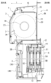
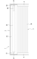
図5、図6は、本実施形態のシャッター1を示す縦断面図であり、巻取軸30の軸方向からみたシャッターガイド50を示している。図5、図6では、シャッターケース2の前面板23とシャッターカーテン3を省略している。
図示のように、シャッター1は、シャッターガイド50に収容された通信部60と、操作部61、62(第1操作部61、第2操作部62)と表示部63のうちの少なくとも一方(いずれか一方又は両方)と、シャッターガイド50の内外に渡って延びるケーブル64を備えている。ここでは、シャッター1は、操作部61、62と表示部63の両方を備えており、操作部61、62と表示部63は、それぞれ通信部60に接続されている。
5 and 6 are vertical cross-sectional views showing the
As shown in the figure, the
通信部60は、外部機器(図示せず)と通信する通信装置であり、無線又は有線で外部機器と接続する。外部機器は、シャッター1の通信部60と無線又は有線で通信可能な外部通信機器であり、シャッター1の外部に設けられている。外部機器は、例えば、シャッター1のリモートコントローラ、シャッター1を遠隔で操作する各種の遠隔操作機器、通信機器、情報処理装置、携帯端末、スマートフォンである。
The
シャッター1は、モータ40を制御する制御部(図示せず)を備えている。制御部は、モータ40を含むシャッター1の各部を制御する制御装置である。モータ40は、制御部により制御されて駆動する。また、制御部により、モータ40の駆動が制御されるとともに、モータ40の回転、モータ40による巻取軸30の回転、シャッターカーテン3の巻取軸30への巻き取り、及び、シャッターカーテン3の巻取軸30からの繰り出しが制御される。通信部60は、直接又は間接に制御部と接続して、外部機器から受信したデータを制御部に向かって送信する。制御部は、通信部60から受信したデータに基づいて、モータ40及びシャッター1の各部を制御する。
The
操作部61、62は、シャッター1の制御部の操作に用いられる操作部品であり、例えば、制御部に信号を出力するスイッチ、制御部に接続するためのコネクタである。ここでは、第1操作部61は、スイッチであり、例えば、リモートコントローラの追加を制御部に指示する操作部として機能する。また、第2操作部62は、コネクタの差込口(レセプタクル)であり、操作装置に設けられたコネクタのプラグが差し込まれて、操作装置による制御部の操作に用いられる操作部として機能する。例えば、操作装置は、シャッター1のメンテナンス用の操作装置であり、第2操作部62に接続する。操作装置の操作により、制御部に記憶されたモータ40の制御プログラムを含む各種のプログラムがアップデートされる。
The
表示部63は、シャッター1の状態を表示する表示装置であり、ここでは、複数の発光素子(例えば、発光ダイオード(LED))を有している。表示部63は、制御部により制御されて、発光素子が発生する光により、シャッター1の各種の状態(状況)を表示する。これにより、表示部63は、例えば、シャッターカーテン3の移動が阻害されてシャッターカーテン3が停止したこと、シャッター1にエラーが生じたこと、又は、シャッター1に通電していることを表示する。
The
シャッターガイド50は、室内側に位置する室内側ガイド部51と、通信部60を収容する収容部52を有している。また、シャッター1は、操作部61、62を覆う着脱可能なカバー部材53を備えている(図5参照)。ここでは、カバー部材53は、シャッターガイド50の一部であり、シャッターガイド50は、それぞれシャッターカーテン3をガイドする複数のガイド部(室内側ガイド部51、収容部52、カバー部材53)に分割されている。シャッターガイド50の室内側ガイド部51、収容部52、及び、カバー部材53は、シャッターカーテン3の側方で、巻取軸30の周方向(回転方向)に沿って順に並べて配置されている。
The
室内側ガイド部51は、収容部52及びカバー部材53の室内側に位置し、巻取軸30よりも上側の位置から巻取軸30よりも室内側の位置を通って巻取軸30よりも下側の位置まで配置されている。収容部52とカバー部材53は、室内側ガイド部51の室外側に位置する室外側ガイド部である。また、収容部52は、シャッターカーテン3をガイドするとともに通信部60を収容する収容ガイド部であり、カバー部材53は、シャッターカーテン3をガイドするとともに操作部61、62を覆うカバーガイド部である。
The
シャッターケース2内で、収容部52は、前面板23(図2参照)と対向して配置され、通信部60は、収容部52の外面に露出しない箇所に配置されている。また、収容部52は、前面板23の室内側(巻取軸30側)に位置して、前面板23と巻取軸30の間に配置されている。収容部52は、カバー部材53の上側に位置し、巻取軸30よりも室外側の位置(前面板23と対向する位置)から上方に向かって巻取軸30よりも上側の位置まで配置されている。ここでは、収容部52は、巻取軸30よりも室外側で巻取軸30の軸心(回転中心)よりも下側の位置から巻取軸30よりも室外側の位置を通って巻取軸30よりも上側の位置まで配置されている。
In the
収容部52の下部54は、巻取軸30よりも室外側の位置(ここでは、巻取軸30よりも室外側で巻取軸30の軸心よりも下側の位置)に配置され、収容部52の上部55は、巻取軸30よりも上側の位置に配置されている。収容部52の下部54は、巻取軸30よりも室外側に位置する収容部52の下端部であり、前面板23の室内側に位置して、前面板23と巻取軸30の間に配置されている。収容部52の上部55は、巻取軸30よりも上側に位置する収容部52の上端部であり、室内側に向けて配置されている。収容部52の下部54は、カバー部材53の上側でカバー部材53と当接し、収容部52の上部55は、巻取軸30よりも上側で室内側ガイド部51と当接している。
The
操作部61、62と表示部63は、収容部52の下部54に設けられている。シャッターケース2に前面板23を取り付けた状態(シャッターケース2に前面板23がある状態)で、収容部52の下部54は、前面板23により、シャッターケース2の室外側の箇所から遮蔽される。これに対し、シャッターケース2から前面板23を取り外した状態(シャッターケース2に前面板23がない状態)では、収容部52の下部54の視認が可能である。
The
収容部52の下部54は、前面板23がない状態で露出する露出部56と、下方に向けて配置された下面部57を有している。表示部63は、露出部56に設けられており、前面板23がない状態で、露出部56と表示部63は、シャッターケース2の室外側の箇所に露出する。露出部56は、収容部52の下部54の室外側の角部に位置し、室内外方向Sに対して傾斜して形成されて、室内側から室外側に向かってみたときに、斜め上方に傾斜する。露出部56と表示部63は、室外側の斜め下方に向けて配置されて、シャッターケース2の室外側及び下側に向かって露出し、シャッター1の室外側の位置から視認される。
The
カバー部材53は、シャッターケース2内で、シャッターカーテン3の側方に配置されている。また、カバー部材53は、前面板23の室内側に位置して、収容部52の下部54及び巻取軸30の下側に配置されている。カバー部材53は、巻取軸30よりも下側で室内側ガイド部51と当接し、室内側ガイド部51から室外側に向かって突出して、収容部52の下部54と当接している。操作部61、62は、収容部52の下部54の下面部57に設けられている。カバー部材53は、下面部57に下側から当接して、下面部57及び操作部61、62を下側から覆う。操作部61、62は、カバー部材53により保護される。
The
収容部52の下部54の露出部56及び表示部63は、カバー部材53よりも室外側に位置し、カバー部材53により覆われない。カバー部材53は、ネジ65により、側板21に着脱可能に取り付けられ、ネジ65を外すことで、側板21から取り外される(図6参照)。カバー部材53を取り外すことで、操作部61、62が露出して、操作部61、62を用いたシャッター1の制御部の操作が可能になる。
The exposed
収容部52は、ケーブル64が挿通する挿通部58を有している。挿通部58は、例えば、挿通孔、又は、挿通口である。挿通部58は、収容部52の上部55に設けられて、巻取軸30よりも上側の位置に配置されている。巻取軸30は、収容部52の上部55及び挿通部58よりも下側に位置し、挿通部58は、室内側ガイド部51と対向する上部55の室内側の箇所に設けられている。ケーブル64は、シャッターケース2内でシャッターカーテン3の側方に配置され、収容部52の内部から挿通部58を挿通して収容部52の外部まで延びる。収容部52の外部で、ケーブル64は、挿通部58から巻取軸30に向かって下側に延びる。
The
モータ40は、巻取軸30の内部に収容される。これに対し、モータ40を制御するシャッター1の制御部は、収容部52に収容され、或いは、巻取軸30に収容される。制御部が収容部52に収容されるときには、通信部60と制御部は、収容部52の内部に収容されて収容部52に固定され、制御部は、収容部52内で直接又は間接に通信部60と接続する。また、ケーブル64は、シャッターカーテン3の側方で、収容部52から巻取軸30に向かって延び、収容部52内の制御部と巻取軸30内のモータ40を接続する。ケーブル64を介して、制御部からモータ40に制御信号が出力されて、モータ40が制御部により制御される。
The
制御部が巻取軸30に収容されるときには、制御部は、モータ40に組み込まれて、モータ40と一体に設けられ、モータ40の一部として巻取軸30の内部に収容される。或いは、制御部は、モータ40とは別に設けられて、モータ40に連結され、巻取軸30の内部にモータ40とともに収容される。制御部は、巻取軸30内で直接又は間接にモータ40と接続する。制御部からモータ40に制御信号が出力されて、モータ40が制御部により制御される。
When the control unit is housed in the winding
モータ40と一体の制御部は、モータ40と内部で接続され、モータ40とは別の制御部は、例えば、ケーブルにより、モータ40と接続される。ここでは、制御部は、モータ40と一体に設けられている。また、ケーブル64は、シャッターカーテン3の側方で、収容部52から巻取軸30に向かって延び、収容部52内の通信部60と巻取軸30内の制御部を接続する。ケーブル64を介して、外部機器から受信したデータが通信部60から制御部に送信される。
The control unit integrated with the
以上説明したシャッター1では、シャッターガイド50の一部である収容部52に通信部60を収容しており、通信部60の取り付け又は保護のための部品を削減することができる。これにより、通信部60をシャッターカーテン3と干渉させずにシャッターケース2内に簡便に設けることができる。また、操作部61、62と表示部63を収容部52の下部54に設けており、前面板23がない状態で、シャッター1の室外側及び室内側から、表示部63の視認や操作部61、62の操作等を容易に行うことができる。そのため、操作部61、62を用いたモータ40の制御部の操作と表示部63の表示によるシャッター1の状態の確認とを容易に行うことができる。
In the
ケーブル64は、シャッターカーテン3の側方で収容部52から巻取軸30に向かって延びる。そのため、ケーブル64がシャッターカーテン3に巻き込まれるのを防止しつつ、シャッターケース2内でケーブル64を簡単に配置することができる。また、シャッター1の制御部が巻取軸30の内部に収容されるときには、通信部60と制御部との距離、及び、通信部60と制御部を接続するケーブル64の長さを短くすることができる。これに対し、シャッター1の制御部が収容部52に収容されるときには、制御部とモータ40の距離、及び、制御部とモータ40を接続するケーブル64の長さを短くすることができる。
The
収容部52の挿通部58が巻取軸30よりも上側の位置に配置されており、巻取軸30よりも上側の箇所で、ケーブル64を挿通部58から巻取軸30に向けて容易に配置することができる。収容部52の下部54の露出部56に表示部63を設けることで、前面板23がない状態で、表示部63を容易に視認することができる。また、シャッターカーテン3が巻取軸30に巻き取られた状態でも、表示部63を視認して、シャッター1の状態を確認することができる。
The
カバー部材53により、操作部61、62を保護することができる。また、操作部61、62を介してシャッター1の制御部が誤って操作されるのを防止することができる。カバー部材53がシャッターガイド50の一部であるため、カバー部材53をシャッターカーテン3の側方に簡単に設けることができる。
The
なお、シャッターガイド50の収容部52の下部54は、収容部52の下端面に位置する下面部57と下面部57の室外側に接続して下面部57に対して傾斜した露出部56を含む。このように、収容部52の下部54は、下面部57のみに限定されず、収容部52において下方に位置する部分である。また、収容部52の下部54の形状は、特に限定されない。例えば、収容部52の下部54の一部又は全体が、室内外方向Sに沿って配置されてもよく、室内外方向Sに対して傾斜していてもよい。収容部52の下部54の露出部56及び露出部56に設けられた表示部63は、光を透過させる部材(例えば、透明又は半透明なシート)で被うようにしてもよい。このように、露出部56は、表示部63を視認可能な部材で被われた露出部を含む。
The
シャッター1は、操作部61、62と表示部63のうちの少なくとも一方を備えていればよい。そのため、シャッター1は、操作部61、62のみ、表示部63のみ、又は、操作部61、62と表示部63の両方を備えていてもよい。また、操作部61、62と表示部63のうちの少なくとも表示部63(表示部63のみ、又は、表示部63と操作部61、62の両方)を備えたシャッター1では、操作部61、62と表示部63のうちの少なくとも表示部63が収容部52の下部54に設けられる。これに対し、操作部61、62と表示部63のうちの少なくとも操作部61、62(操作部61、62のみ、又は、操作部61、62と表示部63の両方)を備えたシャッター1では、操作部61、62と表示部63のうちの少なくとも操作部61、62が収容部52の下部54に設けられる。
The
カバー部材53は、シャッターガイド50の一部でなくてもよい。この場合には、カバー部材53は、シャッターガイド50とは別の部材であり、シャッターカーテン3をガイドする機能を有しない。また、カバー部材53をシャッター1に設けずに、操作部61、62を覆わないようにしてもよい。シャッターガイド50を分割せずに、収容部52を1つのシャッターガイド50の一部に設けてもよい。建具5は、引き違い窓以外の建具であってもよく、本発明は、建具用のシャッター1に限定されず、種々のシャッターに適用することができる。
The
以上のとおり、シャッターは、
シャッターカーテンが連結された巻取軸と、
前記巻取軸及び前記巻取軸に巻き取られた前記シャッターカーテンを収容するシャッターケースと、
前記シャッターケース内で前記シャッターカーテンの側方に配置されたシャッターガイドと、
前記巻取軸を回転させるモータと、
前記モータを制御する制御部と、
前記制御部と接続して外部機器と通信する通信部と、
前記制御部の操作に用いられる操作部とシャッターの状態を表示する表示部のうちの少なくとも一方と、を備え、
前記シャッターケースは、前記巻取軸の室外側に位置する前面板を有し、
前記シャッターガイドは、前記前面板と対向して配置されて、前記通信部を収容する収容部を有し、
前記操作部と前記表示部のうちの少なくとも一方は、前記収容部の下部に設けられたシャッターである。
従って、シャッターの通信部をシャッターカーテンと干渉させずにシャッターケース内に簡便に設けられるとともに、モータの制御部の操作とシャッターの状態の確認のうちの少なくとも一方を容易に行うことができる。
As mentioned above, the shutter
A winding shaft to which the shutter curtain is connected;
A shutter case that accommodates the winding shaft and the shutter curtain wound around the winding shaft;
A shutter guide disposed on a side of the shutter curtain in the shutter case;
A motor that rotates the winding shaft;
A control unit for controlling the motor;
a communication unit connected to the control unit and configured to communicate with an external device;
At least one of an operation unit used to operate the control unit and a display unit that displays a state of the shutter,
The shutter case has a front panel located on the outdoor side of the winding shaft,
the shutter guide has a housing portion disposed opposite the front plate and housing the communication portion,
At least one of the operation unit and the display unit is a shutter provided at a lower part of the storage unit.
Therefore, the communication unit of the shutter can be easily installed inside the shutter case without interfering with the shutter curtain, and at least one of operating the motor control unit and checking the state of the shutter can be easily performed.
前記モータと前記制御部は、前記巻取軸の内部に収容され、
シャッターは、前記シャッターカーテンの側方で前記収容部から前記巻取軸に向かって延び、前記通信部と前記制御部を接続するケーブルを備える。
従って、ケーブルがシャッターカーテンに巻き込まれるのを防止しつつ、シャッターケース内でケーブルを簡単に配置することができる。また、通信部と制御部との距離、及び、通信部と制御部を接続するケーブルの長さを短くすることができる。
The motor and the control unit are housed inside the winding shaft,
The shutter includes a cable that extends from the storage section toward the winding shaft on the side of the shutter curtain and connects the communication section and the control section.
Therefore, the cable can be easily arranged inside the shutter case while preventing the cable from getting entangled in the shutter curtain. Also, the distance between the communication unit and the control unit, and the length of the cable connecting the communication unit and the control unit can be shortened.
前記モータは、前記巻取軸の内部に収容され、
前記制御部は、前記収容部に収容され、
シャッターは、前記シャッターカーテンの側方で前記収容部から前記巻取軸に向かって延び、前記制御部と前記モータを接続するケーブルを備える。
従って、ケーブルがシャッターカーテンに巻き込まれるのを防止しつつ、シャッターケース内でケーブルを簡単に配置することができる。また、制御部とモータの距離、及び、制御部とモータを接続するケーブルの長さを短くすることができる。
The motor is accommodated inside the winding shaft,
The control unit is accommodated in the accommodation unit,
The shutter includes a cable that extends from the storage section toward the winding shaft on the side of the shutter curtain and connects the control section and the motor.
Therefore, the cable can be easily arranged inside the shutter case while preventing the cable from getting entangled in the shutter curtain. Also, the distance between the control unit and the motor, and the length of the cable connecting the control unit and the motor can be shortened.
前記収容部は、前記巻取軸よりも上側の位置に配置されて、前記ケーブルが挿通する挿通部を有する。
従って、巻取軸よりも上側の箇所で、ケーブルを挿通部から巻取軸に向けて容易に配置することができる。
The storage section is disposed at a position above the winding shaft and has an insertion section through which the cable is inserted.
Therefore, the cable can be easily arranged from the insertion portion toward the take-up shaft at a location above the take-up shaft.
シャッターは、前記操作部と前記表示部のうちの少なくとも前記表示部を備え、
前記収容部の下部は、前記前面板がない状態で露出する露出部を有し、
前記表示部は、前記露出部に設けられる。
従って、前面板がない状態で、表示部を容易に視認することができる。また、シャッターカーテンが巻取軸に巻き取られた状態でも、表示部を視認して、シャッターの状態を確認することができる。
the shutter includes at least the display unit out of the operation unit and the display unit,
a lower portion of the housing portion has an exposed portion that is exposed when the front plate is not present,
The display portion is provided on the exposed portion.
Therefore, the display unit can be easily seen even when the front panel is not present. Also, even when the shutter curtain is wound up on the winding shaft, the display unit can be seen to check the shutter state.
シャッターは、前記操作部と前記表示部のうちの少なくとも前記操作部を備え、
前記シャッターケース内で前記シャッターカーテンの側方に配置されて、前記操作部を覆う着脱可能なカバー部材を備える。
従って、カバー部材により、操作部を保護することができる。
the shutter includes at least the operation unit out of the operation unit and the display unit,
A removable cover member is provided which is disposed to the side of the shutter curtain within the shutter case and covers the operating unit.
Therefore, the operating portion can be protected by the cover member.
前記カバー部材は、前記シャッターガイドの一部であり、前記収容部の下部の下側に配置される。
従って、カバー部材をシャッターカーテンの側方に簡単に設けることができる。
The cover member is a part of the shutter guide and is disposed below the lower part of the accommodation portion.
Therefore, the cover member can be easily provided on the side of the shutter curtain.
1・・・シャッター、2・・・シャッターケース、3・・・シャッターカーテン、3A・・・スラット、3B・・・座板、4・・・ガイドレール、5・・・建具、5A・・・第1障子、5B・・・第2障子、5C・・・網戸、6・・・建物、6A・・・壁部、10・・・枠体、11・・・開口部、12・・・上枠、13・・・下枠、14・・・縦枠、15・・・上面板、16・・・収容空間、20・・・裏板、21・・・側板、22・・・側部カバー、23・・・前面板、30・・・巻取軸、31・・・支持軸、40・・・モータ、50・・・シャッターガイド、51・・・室内側ガイド部、52・・・収容部、53・・・カバー部材、54・・・下部、55・・・上部、56・・・露出部、57・・・下面部、58・・・挿通部、60・・・通信部、61・・・第1操作部、62・・・第2操作部、63・・・表示部、64・・・ケーブル、65・・・ネジ、S・・・室内外方向。 1...Shutter, 2...Shutter case, 3...Shutter curtain, 3A...Slat, 3B...Seat board, 4...Guide rail, 5...Fittings, 5A...First shoji screen, 5B...Second shoji screen, 5C...Screen door, 6...Building, 6A...Wall, 10...Frame, 11...Opening, 12...Upper frame, 13...Lower frame, 14...Vertical frame, 15...Top panel, 16...Storage space, 20...Back panel, 21...Side panel, 22...Side Part cover, 23...front panel, 30...winding shaft, 31...support shaft, 40...motor, 50...shutter guide, 51...indoor guide part, 52...storage part, 53...cover member, 54...lower part, 55...upper part, 56...exposed part, 57...underside part, 58...insertion part, 60...communication part, 61...first operation part, 62...second operation part, 63...display part, 64...cable, 65...screw, S...indoor/outdoor direction.
Claims (5)
前記巻取軸及び前記巻取軸に巻き取られた前記シャッターカーテンを収容するシャッターケースと、
前記シャッターケース内で前記シャッターカーテンの側方に配置されたシャッターガイドと、
前記巻取軸を回転させるモータと、
前記モータを制御する制御部と、
前記制御部と接続して外部機器と通信する通信部と、
前記制御部の操作に用いられる操作部とシャッターの状態を表示する表示部のうちの少なくとも一方と、を備え、
前記シャッターケースは、前記巻取軸の室外側に位置する前面板を有し、
前記シャッターガイドは、前記前面板と対向して配置されて、前記通信部を収容する収容部を有し、
前記操作部と前記表示部のうちの少なくとも一方は、前記収容部の下部に設けられ、
前記モータと前記制御部は、前記巻取軸の内部に収容され、
前記シャッターカーテンの側方で前記収容部から前記巻取軸に向かって延び、前記通信部と前記制御部を接続するケーブルを備えたシャッター。 A winding shaft to which the shutter curtain is connected;
A shutter case that accommodates the winding shaft and the shutter curtain wound around the winding shaft;
A shutter guide disposed on a side of the shutter curtain in the shutter case;
A motor that rotates the winding shaft;
A control unit for controlling the motor;
a communication unit connected to the control unit and configured to communicate with an external device;
At least one of an operation unit used to operate the control unit and a display unit that displays a state of the shutter,
The shutter case has a front panel located on the outdoor side of the winding shaft,
the shutter guide has a housing portion disposed opposite the front plate and housing the communication portion,
At least one of the operation unit and the display unit is provided at a lower portion of the storage unit ,
The motor and the control unit are housed inside the winding shaft,
A shutter having a cable extending from the storage section toward the winding shaft on the side of the shutter curtain and connecting the communication section and the control section .
前記収容部は、前記巻取軸よりも上側の位置に配置されて、前記ケーブルが挿通する挿通部を有するシャッター。 2. The shutter according to claim 1 ,
The storage section is disposed at a position above the winding shaft, and has an insertion section through which the cable is inserted.
前記操作部と前記表示部のうちの少なくとも前記表示部を備え、
前記収容部の下部は、前記前面板がない状態で露出する露出部を有し、
前記表示部は、前記露出部に設けられたシャッター。 3. The shutter according to claim 1 or 2 ,
The operation unit and the display unit include at least the display unit,
a lower portion of the housing portion has an exposed portion that is exposed when the front plate is not present,
The display unit is a shutter provided on the exposed portion.
前記操作部と前記表示部のうちの少なくとも前記操作部を備え、
前記シャッターケース内で前記シャッターカーテンの側方に配置されて、前記操作部を覆う着脱可能なカバー部材を備えたシャッター。 3. The shutter according to claim 1 or 2 ,
The operation unit and the display unit include at least the operation unit,
A shutter having a removable cover member that is disposed to the side of the shutter curtain within the shutter case and covers the operating unit.
前記カバー部材は、前記シャッターガイドの一部であり、前記収容部の下部の下側に配置されたシャッター。 5. The shutter according to claim 4 ,
The cover member is a part of the shutter guide, and is a shutter arranged below the lower part of the storage section.
Priority Applications (1)
| Application Number | Priority Date | Filing Date | Title |
|---|---|---|---|
| JP2021108433A JP7650737B2 (en) | 2021-06-30 | 2021-06-30 | shutter |
Applications Claiming Priority (1)
| Application Number | Priority Date | Filing Date | Title |
|---|---|---|---|
| JP2021108433A JP7650737B2 (en) | 2021-06-30 | 2021-06-30 | shutter |
Publications (2)
| Publication Number | Publication Date |
|---|---|
| JP2023006049A JP2023006049A (en) | 2023-01-18 |
| JP7650737B2 true JP7650737B2 (en) | 2025-03-25 |
Family
ID=85107346
Family Applications (1)
| Application Number | Title | Priority Date | Filing Date |
|---|---|---|---|
| JP2021108433A Active JP7650737B2 (en) | 2021-06-30 | 2021-06-30 | shutter |
Country Status (1)
| Country | Link |
|---|---|
| JP (1) | JP7650737B2 (en) |
Families Citing this family (1)
| Publication number | Priority date | Publication date | Assignee | Title |
|---|---|---|---|---|
| JP7743353B2 (en) * | 2022-04-07 | 2025-09-24 | Ykk Ap株式会社 | Electric shutter |
Citations (5)
| Publication number | Priority date | Publication date | Assignee | Title |
|---|---|---|---|---|
| JP2003221987A (en) | 2002-01-30 | 2003-08-08 | Ykk Ap Inc | Motor driven shutter |
| JP2010196358A (en) | 2009-02-25 | 2010-09-09 | Ykk Ap株式会社 | Electric shutter |
| JP2014234593A (en) | 2013-05-31 | 2014-12-15 | 三和シヤッター工業株式会社 | Electric shutter apparatus for building |
| US20170328126A1 (en) | 2016-05-10 | 2017-11-16 | Nicholas Jay Bonge, JR. | Pet door system having semi-flexible pet door |
| JP2020165107A (en) | 2019-03-28 | 2020-10-08 | 文化シヤッター株式会社 | Switchgear structure |
Family Cites Families (6)
| Publication number | Priority date | Publication date | Assignee | Title |
|---|---|---|---|---|
| JPH0460090A (en) * | 1990-06-27 | 1992-02-26 | Toso Co Ltd | Tubular motor device for winding type closing member |
| FR2911364B1 (en) * | 2007-01-16 | 2010-12-03 | Bubendorff | HEADER FOR SHUTTER MOTOR HEAD |
| JP5706114B2 (en) * | 2010-09-01 | 2015-04-22 | トーソー株式会社 | Motorized remote control system for electric curtain |
| JP6594076B2 (en) * | 2015-07-22 | 2019-10-23 | 文化シヤッター株式会社 | Switchgear |
| JP7098460B2 (en) * | 2018-07-19 | 2022-07-11 | 文化シヤッター株式会社 | How to disassemble the switchgear and switchgear |
| JP7105651B2 (en) * | 2018-08-28 | 2022-07-25 | 三和シヤッター工業株式会社 | Cable for measurement |
-
2021
- 2021-06-30 JP JP2021108433A patent/JP7650737B2/en active Active
Patent Citations (5)
| Publication number | Priority date | Publication date | Assignee | Title |
|---|---|---|---|---|
| JP2003221987A (en) | 2002-01-30 | 2003-08-08 | Ykk Ap Inc | Motor driven shutter |
| JP2010196358A (en) | 2009-02-25 | 2010-09-09 | Ykk Ap株式会社 | Electric shutter |
| JP2014234593A (en) | 2013-05-31 | 2014-12-15 | 三和シヤッター工業株式会社 | Electric shutter apparatus for building |
| US20170328126A1 (en) | 2016-05-10 | 2017-11-16 | Nicholas Jay Bonge, JR. | Pet door system having semi-flexible pet door |
| JP2020165107A (en) | 2019-03-28 | 2020-10-08 | 文化シヤッター株式会社 | Switchgear structure |
Also Published As
| Publication number | Publication date |
|---|---|
| JP2023006049A (en) | 2023-01-18 |
Similar Documents
| Publication | Publication Date | Title |
|---|---|---|
| US10597940B2 (en) | Motor-driven control device for controlling a movable screen consisting of a windable canvas of a window-covering device or projection screen | |
| US11713619B2 (en) | Screening device | |
| WO2002006621A1 (en) | A screening arrangement | |
| JP7650737B2 (en) | shutter | |
| US10934773B2 (en) | Motorized manoeuvring device intended to manoeuvre a moving windable fabric screen of a window or projection screen cover device | |
| KR100859269B1 (en) | Binder Type Curtain Device | |
| JP6783158B2 (en) | blind | |
| JP6798903B2 (en) | shutter | |
| EP4006295B1 (en) | A screening arrangement for a roof window, and roof window comprising such a screening arrangement | |
| JP5122069B2 (en) | shutter | |
| JP6497979B2 (en) | Shutter fire prevention structure | |
| CN117980579A (en) | Motor components for building opening covering systems | |
| JP2024139030A (en) | shutter | |
| JP2017179875A (en) | Receiver | |
| JP2024139031A (en) | shutter | |
| JP7664825B2 (en) | Remote control light receiving structure for electric shading device | |
| JP2018137322A (en) | Wiring housing structure | |
| JP7769591B2 (en) | Electric blinds | |
| JP7614079B2 (en) | Electric shutter device | |
| JP7743353B2 (en) | Electric shutter | |
| JP2025062776A (en) | Wiring structure of electric shutter | |
| JP7807999B2 (en) | Electric blinds | |
| JP6454134B2 (en) | Shutter box mounting structure | |
| EP4095344A1 (en) | Control device for lighting elements to be mounted on a roll-up cover installation | |
| JP2025062513A (en) | Electric shutter |
Legal Events
| Date | Code | Title | Description |
|---|---|---|---|
| A621 | Written request for application examination |
Free format text: JAPANESE INTERMEDIATE CODE: A621 Effective date: 20240411 |
|
| RD02 | Notification of acceptance of power of attorney |
Free format text: JAPANESE INTERMEDIATE CODE: A7422 Effective date: 20240604 |
|
| RD04 | Notification of resignation of power of attorney |
Free format text: JAPANESE INTERMEDIATE CODE: A7424 Effective date: 20240606 |
|
| A977 | Report on retrieval |
Free format text: JAPANESE INTERMEDIATE CODE: A971007 Effective date: 20241023 |
|
| A131 | Notification of reasons for refusal |
Free format text: JAPANESE INTERMEDIATE CODE: A131 Effective date: 20241029 |
|
| A521 | Request for written amendment filed |
Free format text: JAPANESE INTERMEDIATE CODE: A523 Effective date: 20241212 |
|
| TRDD | Decision of grant or rejection written | ||
| A01 | Written decision to grant a patent or to grant a registration (utility model) |
Free format text: JAPANESE INTERMEDIATE CODE: A01 Effective date: 20250218 |
|
| A61 | First payment of annual fees (during grant procedure) |
Free format text: JAPANESE INTERMEDIATE CODE: A61 Effective date: 20250312 |
|
| R150 | Certificate of patent or registration of utility model |
Ref document number: 7650737 Country of ref document: JP Free format text: JAPANESE INTERMEDIATE CODE: R150 |