JP6594076B2 - Switchgear - Google Patents

Switchgear Download PDF

Info

Publication number
JP6594076B2
JP6594076B2 JP2015145069A JP2015145069A JP6594076B2 JP 6594076 B2 JP6594076 B2 JP 6594076B2 JP 2015145069 A JP2015145069 A JP 2015145069A JP 2015145069 A JP2015145069 A JP 2015145069A JP 6594076 B2 JP6594076 B2 JP 6594076B2
Authority
JP
Japan
Prior art keywords
wiring
control unit
opening
motor unit
motor
Prior art date
Legal status (The legal status is an assumption and is not a legal conclusion. Google has not performed a legal analysis and makes no representation as to the accuracy of the status listed.)
Active
Application number
JP2015145069A
Other languages
Japanese (ja)
Other versions
JP2017025583A (en
Inventor
正和 重村
寿一 和田
正典 小林
勝彦 村上
Current Assignee (The listed assignees may be inaccurate. Google has not performed a legal analysis and makes no representation or warranty as to the accuracy of the list.)
Bunka Shutter Co Ltd
Original Assignee
Bunka Shutter Co Ltd
Priority date (The priority date is an assumption and is not a legal conclusion. Google has not performed a legal analysis and makes no representation as to the accuracy of the date listed.)
Filing date
Publication date
Application filed by Bunka Shutter Co Ltd filed Critical Bunka Shutter Co Ltd
Priority to JP2015145069A priority Critical patent/JP6594076B2/en
Publication of JP2017025583A publication Critical patent/JP2017025583A/en
Application granted granted Critical
Publication of JP6594076B2 publication Critical patent/JP6594076B2/en
Active legal-status Critical Current
Anticipated expiration legal-status Critical

Links

Images

Description

本発明は、シャッターカーテン等の開閉体を開閉駆動する開閉装置に関する。   The present invention relates to an opening / closing device that opens and closes an opening / closing body such as a shutter curtain.

従来、シャッター装置やオーバーヘッドドア等において、制御部等に対するメンテナンス性を向上させた開閉装置が知られている(例えば特許文献1参照)。この開閉装置は、開閉機が、駆動軸側を巻取体の一端部の近傍に配置する。開閉機は、反駆動軸側を巻取体の他端方向へ向けて固定される。収納部の下面には、点検口と、該点検口を開放可能に閉鎖する閉鎖部材とが設けられる。制御部は、制御のための信号線接続部を少なくとも有する被作業面を、反駆動軸側へ向けて、開閉機の上部または下部に固定される。収納部内には、制御部の被作業面よりも反駆動軸側に、被作業面に対する作業を行うための作業空間が確保される。点検口は、開閉機及び作業空間を含む範囲に開口されている。   2. Description of the Related Art Conventionally, an opening / closing device with improved maintainability for a control unit or the like in a shutter device or an overhead door is known (for example, see Patent Document 1). In this opening / closing apparatus, the opening / closing machine has the drive shaft side disposed in the vicinity of one end of the winding body. The opening / closing machine is fixed with the counter drive shaft side directed toward the other end of the winding body. An inspection port and a closing member that closes the inspection port so as to be openable are provided on the lower surface of the storage unit. The control unit is fixed to an upper part or a lower part of the switch with a work surface having at least a signal line connection part for control facing the counter drive shaft side. A working space for performing work on the work surface is secured in the storage portion on the side opposite to the drive shaft from the work surface of the control unit. The inspection port is opened in a range including the switch and the work space.

特開2015−81494号公報Japanese Patent Laying-Open No. 2015-81494

しかしながら、上記した従来の開閉装置は、制御部が開閉機(モータ部)に固定されているため、設置後を考えて大きくすると、運搬や施工がしにくくなり、逆に小さくすると、使い勝手が悪くなる問題があった。通常、シャッター装置の施工やメンテナンスは、建物開口上部である開閉体収容部の下面に設けられた点検口から行う。制御部の被作業面は、下から点検口を通じての作業であるのに対し、横面(垂直面)が操作面となっており、且つ点検口からは奥方向(上方向)に位置しているため、作業性がとても悪い問題があった。
また、モータ部と制御部とを接続する配線や制御部に接続される各種配線が、明確な収納スペースや束ね方がなく、現場での施工の熟練度に頼っており、品質が悪いと、開閉体などに引っ掛かることでの断線や、雨水による漏電などが発生する虞があった。また、束ね方も施工時に任されることでそれぞれであり、粘着テープなどを使用すると作業が煩雑な上、メンテナンスもし難い問題があった。
However, in the above-described conventional switchgear, since the control unit is fixed to the switchgear (motor unit), it is difficult to carry and work if it is made large after installation, and conversely, if it is made small, the usability is poor. There was a problem. Usually, the construction and maintenance of the shutter device are performed from an inspection port provided on the lower surface of the opening / closing body housing part, which is the upper part of the building opening. The work surface of the control unit is the work through the inspection port from the bottom, while the horizontal surface (vertical surface) is the operation surface and is located in the back direction (upward) from the inspection port. Therefore, there was a problem that workability was very bad.
In addition, the wiring that connects the motor unit and the control unit and the various wirings that are connected to the control unit do not have a clear storage space or bundling, rely on the skill level of construction on site, and if the quality is poor, There was a risk of disconnection due to being caught on an opening / closing body or leakage of electricity due to rainwater. In addition, the method of bundling is left up to the time of construction, and the use of an adhesive tape has a problem that the work is complicated and the maintenance is difficult.

本発明は上記状況に鑑みてなされたもので、その目的は、梱包、運搬、設置時に各作業等において作業をし易くでき、また、設置時及び設置後においての作業性、メンテナンス性など使いやすくできる開閉装置を提供することにある。   The present invention has been made in view of the above circumstances, and its purpose is to make it easy to work in each work, etc. during packaging, transportation, and installation, and to make it easy to use, such as workability and maintainability during and after installation. An object of the present invention is to provide a switchgear that can be used.

次に、上記の課題を解決するための手段を、実施の形態に対応する図面を参照して説明する。
本発明の開閉装置11は、建物開口部15の上縁近傍に設けられる開閉体収容部19に内設され、前記建物開口部15を開閉する開閉体17を巻き取り繰り出し駆動するモータ部37と、
前記モータ部37の上方に配置され、前記モータ部37と制御配線53を介して接続されて前記モータ部37の駆動を制御する制御部39と、
前記モータ部37と前記制御部39とに亘って設けられ、前記制御部39を前記モータ部37と上下に重なる位置と前記制御部39を前記開閉体17の巻き取り中心軸に沿う方向へオフセットさせて前記制御部39の下面の一部を下向きに露出させた位置とに配置する連結手段と、
を具備する。
Next, means for solving the above problems will be described with reference to the drawings corresponding to the embodiments.
Opening and closing device 11 of the present invention is provided inside the opening and closing member housing portion 19 provided near the edge on the building opening 15, the motor unit 37 for opening and closing member 17 winding feeding drives for opening and closing the building opening 15 When,
A control unit 39 disposed above the motor unit 37 and connected to the motor unit 37 via a control wiring 53 to control driving of the motor unit 37;
Provided across the motor unit 37 and the control unit 39, the control unit 39 is vertically offset from the motor unit 37, and the control unit 39 is offset in a direction along the winding center axis of the opening / closing body 17. And connecting means for disposing a part of the lower surface of the control unit 39 exposed downward,
It includes a.

この開閉装置11では、制御部39が、梱包、運搬、設置時に、モータ部37と上下に重なる位置で配置され、巻き取り中心軸に沿う方向の寸法が小さくなる。開閉装置11は、開閉体収容部19へ搬入し、モータ部37が固定された後には、制御部39が開閉体17の巻き取り中心軸に沿う方向へ移動してモータ部37に対しオフセットした位置に配置される。制御部39は、このオフセットした位置で、下面の一部がモータ部37からはみ出した位置となり、下方からのアクセスが可能となる。   In the switchgear 11, the control unit 39 is disposed at a position overlapping the motor unit 37 in the vertical direction during packing, transportation, and installation, and the dimension in the direction along the winding center axis is reduced. After the opening / closing device 11 is carried into the opening / closing body accommodating portion 19 and the motor portion 37 is fixed, the control portion 39 moves in a direction along the winding center axis of the opening / closing body 17 and is offset with respect to the motor portion 37. Placed in position. At this offset position, the control unit 39 is in a position where a part of the lower surface protrudes from the motor unit 37 and can be accessed from below.

本発明の請求項記載の開閉装置11は、上記の開閉装置11であって、
前記連結手段は、前記巻き取り中心軸に沿う方向をスライド方向として延在するレール溝93と、前記レール溝93に係合する係合片91と、を有することを特徴とする。
本発明の請求項5記載の開閉装置は、上記連結手段は、底板の長辺縁部から一対の側板部が起立し上方が開放されて形成される連結具を有し、連結具の一対の側板部の上端には、前記巻き取り中心軸に沿う方向をスライド方向として延在する前記レール溝を有し、前記制御部の下面における前記被作業面を挟む両側には前記レール溝に係合する前記係合片を有することを特徴とする。
The switchgear 11 according to claim 4 of the present invention is the switchgear 11 described above ,
The connecting means includes a rail groove 93 extending with the direction along the winding center axis as a sliding direction, and an engagement piece 91 engaged with the rail groove 93.
The opening / closing apparatus according to claim 5 of the present invention is characterized in that the connecting means has a connecting tool formed by a pair of side plate portions rising from the long side edge of the bottom plate and opened upward, and the pair of connecting tools. At the upper end of the side plate portion, there is the rail groove extending with the direction along the winding center axis as the sliding direction, and the rail groove engages with the rail groove on both sides of the work surface on the lower surface of the control unit. It has the above-mentioned engagement piece to do.

この開閉装置11では、モータ部37と制御部39の何れか一方にレール溝93が設けられ、このレール溝93に係合する係合片91が、モータ部37と制御部39の何れか他方に設けられる。制御部39は、これらレール溝93と係合片91とが摺動することで、スライド自在となってモータ部37とともに巻き取り中心軸に沿う方向に伸び縮みが可能となる。レール溝93は、例えば板金材からなる連結手段の側板にコ字形状の折り曲げ部を形成することで容易に得ることができる。係合片91は、例えば制御部39の下面におけるレール溝93に対応する平行な縁部に形成される鍔状部として容易に得ることができる。   In the opening / closing device 11, a rail groove 93 is provided in one of the motor unit 37 and the control unit 39, and the engaging piece 91 that engages with the rail groove 93 is either the motor unit 37 or the control unit 39. Is provided. As the rail groove 93 and the engagement piece 91 slide, the control unit 39 becomes slidable and can be expanded and contracted in the direction along the winding center axis together with the motor unit 37. The rail groove 93 can be easily obtained by forming a U-shaped bent portion on the side plate of the connecting means made of, for example, a sheet metal material. The engagement piece 91 can be easily obtained, for example, as a bowl-shaped portion formed on a parallel edge corresponding to the rail groove 93 on the lower surface of the control unit 39.

本発明の請求項記載の開閉装置11は、上記の開閉装置11であって、
前記制御部39は、前記オフセットされた位置で前記モータ部37から外れた前記下面の一部に、被作業面63を備えることを特徴とする。
Closing device 11 according to a first aspect of the present invention, there is provided a closing device 11 of the above SL,
The control unit 39 includes a work surface 63 on a part of the lower surface that is detached from the motor unit 37 at the offset position.

この開閉装置11では、制御部39がモータ部37に対して開閉体17の巻き取り中心軸に沿う方向へオフセットされた位置とされ、モータ部37から外れた下面の一部に、制御部39の被作業面63が配置される。すなわち、被作業面63は、梱包、運搬、設置時には、モータ部37に重ねられた状態に覆われて保護される。一方、被作業面63は、モータ部37が固定された後には、モータ部37に対してスライドするなど開閉体17の巻き取り中心軸に沿う方向へオフセットされた位置に配置されることで露出して操作が可能となる。開閉装置11は、開閉体収容部19の下板45近傍に配置されることから、この下板45に設けられた点検口57からアクセスされる。この際、被作業面63は、下面に配置されているので、点検口57に向くこととなり、この点検口57の入口近傍でアクセスが容易に可能となる。従来装置のように、垂直面に設けられることにより、点検口57の奥まで頭や手を入れて操作する必要がなく、施工時の設定や、運用後の調整、メンテナンス等が容易に行えるようになる。   In the opening / closing device 11, the control unit 39 is offset with respect to the motor unit 37 in the direction along the winding center axis of the opening / closing body 17, and the control unit 39 is formed on a part of the lower surface removed from the motor unit 37. The work surface 63 is arranged. That is, the work surface 63 is covered and protected by being overlaid on the motor unit 37 during packaging, transportation, and installation. On the other hand, the work surface 63 is exposed by being arranged at a position offset in a direction along the winding central axis of the opening / closing body 17 such as sliding with respect to the motor unit 37 after the motor unit 37 is fixed. And can be operated. Since the opening / closing device 11 is disposed in the vicinity of the lower plate 45 of the opening / closing body accommodating portion 19, the opening / closing device 11 is accessed from an inspection port 57 provided in the lower plate 45. At this time, since the work surface 63 is disposed on the lower surface, the work surface 63 faces the inspection port 57 and can be easily accessed in the vicinity of the entrance of the inspection port 57. Because it is provided on a vertical surface as in the conventional device, it is not necessary to operate with the head or hand in the depths of the inspection port 57, making it easy to perform setup, adjustment after operation, maintenance, etc. become.

本発明の請求項記載の開閉装置11は、上記の開閉装置11であって、
前記連結手段は、前記巻き取り中心軸に沿う方向に貫通する配線収容部115を備え、前記配線収容部115には少なくとも前記制御配線53が収容されることを特徴とする。
The switchgear 11 according to claim 2 of the present invention is the switchgear 11 described above ,
The connecting means includes a wiring accommodating portion 115 that penetrates in a direction along the winding central axis, and at least the control wiring 53 is accommodated in the wiring accommodating portion 115.

この開閉装置11では、制御部39がモータ部37に対して、開閉体17の巻き取り中心軸に沿う方向へオフセットされた位置となる。この制御部39とモータ部37とに亘って配置される連結手段には、巻き取り中心軸に沿う方向に貫通する配線収容部115が設けられる。制御部39とモータ部37とは、制御配線53によって接続される。この制御配線53は、配線収容部115に収容される。制御配線53は、余長を有して配索されることで、制御部39のオフセット位置への移動を阻害することがない。これにより、制御配線53は、連結手段の内方に収容されて、開閉体17などに引っ掛かることでの断線や、雨水による漏電などが発生しなくなる。   In the opening / closing device 11, the control unit 39 is offset with respect to the motor unit 37 in the direction along the winding center axis of the opening / closing body 17. The connecting means disposed between the control unit 39 and the motor unit 37 is provided with a wiring housing unit 115 penetrating in a direction along the winding center axis. The control unit 39 and the motor unit 37 are connected by a control wiring 53. The control wiring 53 is accommodated in the wiring accommodating portion 115. The control wiring 53 is routed with a surplus length so that the movement of the control unit 39 to the offset position is not hindered. As a result, the control wiring 53 is accommodated inside the connecting means, and disconnection due to being caught by the opening / closing body 17 or leakage of electricity due to rainwater does not occur.

本発明の請求項記載の開閉装置11は、上記の開閉装置11であって、
前記連結手段は、前記配線収容部115の外面に現場施工配線29を保持する配線保持部121を有することを特徴とする。
The switchgear 11 according to claim 3 of the present invention is the switchgear 11 described above ,
The connecting means includes a wiring holding part 121 that holds the on-site construction wiring 29 on the outer surface of the wiring accommodating part 115.

この開閉装置11では、現場にて配索される現場施工配線29が、連結手段の外面に設けられた配線保持部121によって保持される。つまり、工場で結線する配線スペースと、現場で結線する配線スペースとを分けることができる。これにより、工場で予め結線する制御配線53は連結手段の内部側、現場にて結線する現場施工配線29は連結手段の外部側にそれぞれ収納、保持できる。これにより、配線をし易く、分かりやすくし、作業性、メンテナンス性の向上を図れ、且つ開閉体17などに引っ掛かることでの断線や、雨水による漏電などが発生しなくなる。   In the switchgear 11, the on-site construction wiring 29 routed on site is held by a wiring holding part 121 provided on the outer surface of the connecting means. That is, it is possible to separate the wiring space that is connected at the factory and the wiring space that is connected at the site. Thereby, the control wiring 53 connected in advance at the factory can be stored and held inside the connecting means, and the on-site construction wiring 29 connected at the site can be stored and held respectively. Thereby, wiring is easy and easy to understand, workability and maintainability can be improved, and disconnection due to being caught on the opening / closing body 17 or leakage of electricity due to rainwater does not occur.

本発明に係る請求項1記載の開閉装置によれば、モータ部と制御部とを上下に重なる位置に配置する形態と、モータ部と制御部とを巻き取り中心軸に沿う方向へ制御部がモータ部に対してオフセットした位置とする形態との2形態にできることで、開閉装置として全体を伸び縮みするような形状にでき、これにより、梱包、運搬、設置時にはコンパクトにしてこれら作業をし易くでき、また、設置後には必要な面である制御部下面の一部を大きく露出させて使いやすくできる。   According to the switchgear of the first aspect of the present invention, the controller is configured so that the motor unit and the control unit are arranged in a vertically overlapping position, and the motor unit and the controller are wound in the direction along the winding center axis. By being able to make two forms, the position offset with respect to the motor part, it can be made into a shape that expands and contracts as a whole as an opening and closing device, which makes it easy to make these operations compact when packing, transporting, installing In addition, after installation, a part of the lower surface of the control unit, which is a necessary surface, is greatly exposed to facilitate use.

本発明に係る請求項4または5記載の開閉装置によれば、レール溝と係合片とのスライド構造によって、開閉装置全体を簡素且つ安価な構造で巻き取り中心軸に沿う方向で伸び縮み可能とすることができる。 According to the switchgear according to claim 4 or 5 of the present invention, the entire switchgear can be expanded and contracted in the direction along the winding center axis with a simple and inexpensive structure by the slide structure of the rail groove and the engagement piece. It can be.

本発明に係る請求項記載の開閉装置によれば、設置時及び設置後に、制御部の被作業面がモータ部から外れた下面の一部に配置され、これにより、被作業面は露出して操作が可能となり、そして、この被作業面は、下面に配置されているので、開閉体収容部の点検口に向くこととなり、この点検口の入口近傍でアクセスが容易に可能となり、制御部への設定作業や、メンテナンス時における制御値などの調整を行いやすくできる。また、被作業面は、梱包、運搬、設置時には、モータ部に重ねられた状態に覆われることになり、すなわち保護されることとなる。 According to the switchgear of the first aspect of the present invention, the work surface of the control unit is disposed on a part of the lower surface that is detached from the motor unit during and after installation, whereby the work surface is exposed. Since the work surface is disposed on the lower surface, the work surface is directed to the inspection port of the opening / closing body housing portion, and access is easily possible near the entrance of the inspection port. This makes it easier to adjust the control values and other settings during maintenance. In addition, the work surface is covered with a state of being overlaid on the motor unit during packaging, transportation, and installation, that is, protected.

本発明に係る請求項記載の開閉装置によれば、連結手段に備えられる配線収容部に、制御部とモータ部とを接続する制御配線を収容することができ、これにより、制御配線は、開閉体などに引っ掛かることでの断線などが発生しなくなり、また、制御配線の判別を容易にして、メンテナンス性を向上させることができる。 According to the switchgear according to claim 2 of the present invention, the control wiring that connects the control section and the motor section can be accommodated in the wiring accommodation section provided in the connecting means. A disconnection or the like due to being caught on the opening / closing body or the like does not occur, and the control wiring can be easily discriminated and the maintainability can be improved.

本発明に係る請求項記載の開閉装置によれば、連結手段の配線収容部の外面に配線保持部を備えることで、現場施工配線を保持させることができ、すなわち、工場で結線する配線スペースと、現場で結線する配線スペースとを分けることができる。これにより、工場で予め結線する制御配線は連結手段の内部側、現場にて結線する現場施工配線は連結手段の外部側にそれぞれ収納、保持でき、各種配線をし易く、分かりやすくし、施工品質を一定に保つことができるとともに、作業性、メンテナンス性の向上を図れ、且つ開閉体などに引っ掛かることでの断線などが発生しなくなる。 According to the switchgear according to claim 3 of the present invention, it is possible to hold the on-site construction wiring by providing the wiring holding portion on the outer surface of the wiring housing portion of the connecting means, that is, the wiring space to be connected at the factory. And the wiring space to be connected on site can be separated. As a result, the control wiring that is pre-wired at the factory can be stored and held on the inside of the connecting means, and the on-site construction wiring that is connected on-site can be stored and held on the outside of the connecting means. Can be kept constant, workability and maintainability can be improved, and disconnection due to being caught on the opening / closing body or the like does not occur.

本発明の実施形態に係る開閉装置を備えるシャッター装置の正面図である。It is a front view of a shutter apparatus provided with the opening / closing apparatus which concerns on embodiment of this invention. 図1に示した開閉装置の正面図である。It is a front view of the switchgear shown in FIG. 開閉体収容部に設けられた開閉装置の斜視図である。It is a perspective view of the opening / closing apparatus provided in the opening / closing body accommodating part. 制御部の下面図である。It is a bottom view of a control part. 連結手段を構成する連結具の斜視図である。It is a perspective view of the connector which comprises a connection means. 開閉装置の側面図である。It is a side view of an opening / closing device. 梱包時における開閉装置の斜視図である。It is a perspective view of the switchgear at the time of packing. 施工時における開閉装置の側面図である。It is a side view of the switchgear at the time of construction. 現場施工配線の接続時を表す開閉装置の下面図である。It is a bottom view of the switchgear showing the time of connection of field construction wiring. 変形例に係る配線保持部を備えた連結具の斜視図である。It is a perspective view of a connector provided with the wiring holding part concerning a modification. 他の変形例に係る配線保持部を備えた連結具の斜視図である。It is a perspective view of the coupling tool provided with the wiring holding part which concerns on another modification.

以下、本発明に係る実施形態を図面を参照して説明する。
図1は本発明の実施形態に係る開閉装置11を備えるシャッター装置13の正面図である。
本実施形態に係る開閉装置11は、住宅やビル、倉庫、工場、商業施設などの建物開口部15に設置されるシャッター装置13に好適に用いることができる。開閉装置11は、この他、車両の荷台などに設けられる開閉体にも適用可能なものである。
Embodiments according to the present invention will be described below with reference to the drawings.
FIG. 1 is a front view of a shutter device 13 including an opening / closing device 11 according to an embodiment of the present invention.
The opening / closing device 11 according to the present embodiment can be suitably used for a shutter device 13 installed in a building opening 15 such as a house, building, warehouse, factory, or commercial facility. In addition, the opening / closing device 11 can also be applied to an opening / closing body provided in a loading platform of a vehicle.

シャッター装置13は、建物開口部15を開閉する開閉体としてのシャッターカーテン17が、建物躯体に配設された開閉体収容部19に対し、巻き取り・繰り出される。開閉体収容部19は、建物開口部15の上縁近傍、例えばまぐさに沿って設けられる。建物開口部15を昇降するシャッターカーテン17は、左右(図1の左右)の壁部21に固定されたガイドレール23によってガイドされて昇降する。開閉体収容部19は、一対のブラケット25によって左右両側部が建物躯体に固定されるとともに、巻取シャフト27、開閉装置11を有している。開閉装置11には、現場施工配線29である電源配線、複数のセンサ用配線31、操作スイッチ用配線33などが現場施工により接続される。電源配線は、建物分電盤からの商用電源と接続される。センサ用配線31は、例えば上下限リミットスイッチ、急降下停止用スイッチ、ビームセンサなどと接続される。操作スイッチ用配線33は、壁部21に取り付けられる操作スイッチパネル35と接続される。   In the shutter device 13, a shutter curtain 17 as an opening / closing body that opens and closes a building opening 15 is wound and fed out to an opening / closing body accommodating portion 19 disposed in the building housing. The opening / closing body accommodating portion 19 is provided in the vicinity of the upper edge of the building opening 15, for example, along the lintel. The shutter curtain 17 that moves up and down the building opening 15 is lifted and lowered by being guided by guide rails 23 fixed to the left and right (left and right in FIG. 1) wall portions 21. The opening / closing body accommodating portion 19 is fixed to the building frame by a pair of brackets 25 and has a winding shaft 27 and an opening / closing device 11. The switchgear 11 is connected to power supply wiring, which is field construction wiring 29, a plurality of sensor wirings 31, an operation switch wiring 33, and the like by field construction. The power supply wiring is connected to the commercial power supply from the building distribution board. The sensor wiring 31 is connected to, for example, an upper / lower limit switch, a sudden descent stop switch, a beam sensor, or the like. The operation switch wiring 33 is connected to the operation switch panel 35 attached to the wall portion 21.

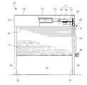
図2は図1に示した開閉装置11の正面図である。
本実施形態に係る開閉装置11は、モータ部37と、制御部39と、連結手段と、を主要な構成として有する。開閉装置11は、左右勝手により一対のブラケット25の何れか一方に固定される。開閉装置11は、開閉体収容部19の開閉体収容部外側板43や開閉体収容部下板45などによって覆われる。
FIG. 2 is a front view of the switchgear 11 shown in FIG.
The opening / closing apparatus 11 according to the present embodiment includes a motor unit 37, a control unit 39, and a connecting unit as main components. The opening / closing device 11 is fixed to either one of the pair of brackets 25 by right and left. The opening / closing device 11 is covered with an opening / closing body housing outer plate 43 and an opening / closing body housing lower plate 45 of the opening / closing body housing 19.

モータ部37は、軸線方向がシャッターカーテン17の巻き取り中心軸に沿う方向となった略円柱形状となる。巻取シャフト27の一端側(図2の右端側)にはシャフトスプロケット47(図3参照)が固定される。モータ部37の一端側には、駆動軸が突出する。駆動軸には、駆動ギア49(図2参照)が固定される。駆動ギア49とシャフトスプロケット47とには、駆動力伝達チェーン51が掛け渡される。これにより、巻取シャフト27は、モータ部37からの回転駆動力が伝達されることで正逆回転される。すなわち、モータ部37は、開閉体収容部19に内設され、建物開口部15を開閉するシャッターカーテン17を、巻取シャフト27の回転によって、巻き取り繰り出し駆動する。   The motor unit 37 has a substantially cylindrical shape in which the axial direction is a direction along the winding center axis of the shutter curtain 17. A shaft sprocket 47 (see FIG. 3) is fixed to one end side of the winding shaft 27 (right end side in FIG. 2). A drive shaft projects from one end side of the motor unit 37. A drive gear 49 (see FIG. 2) is fixed to the drive shaft. A driving force transmission chain 51 is stretched between the driving gear 49 and the shaft sprocket 47. Thereby, the winding shaft 27 is rotated forward and backward by the rotational driving force transmitted from the motor unit 37. In other words, the motor unit 37 is installed in the opening / closing body accommodating unit 19 and drives the shutter curtain 17 that opens and closes the building opening 15 to be wound and fed by the rotation of the winding shaft 27.

制御部39は、モータ部37の上方に配置される。制御部39は、モータ部37と制御配線53を介して接続されて、モータ部37の駆動を制御する。制御部39とモータ部37とは、後述する連結具41の内部に挿通された制御配線53によって結線される。また、制御部39には、電源配線、センサ用配線、操作スイッチ用配線などの現場施工配線29がコネクタによって接続される。   The control unit 39 is disposed above the motor unit 37. The control unit 39 is connected to the motor unit 37 via the control wiring 53 and controls the driving of the motor unit 37. The control part 39 and the motor part 37 are connected by the control wiring 53 inserted in the inside of the coupling tool 41 mentioned later. Further, on-site construction wiring 29 such as power supply wiring, sensor wiring, operation switch wiring, and the like is connected to the control unit 39 by a connector.

図3は開閉体収容部19に設けられた開閉装置11の斜視図である。
開閉装置11には、停電時の手動巻き上げ具としてのチェーン55を備える。このチェーン55は、開閉体収容部下板45に設けられる点検口57の近傍に設置された掛金具を介して常備状態で保管される。
FIG. 3 is a perspective view of the opening / closing device 11 provided in the opening / closing body accommodating portion 19.
The switchgear 11 is provided with a chain 55 as a manual hoisting tool at the time of power failure. The chain 55 is stored in a ready state via a metal fitting installed in the vicinity of the inspection port 57 provided in the lower plate 45 of the opening / closing body accommodating portion.

図4は制御部39の下面図である。
制御部39は、略直方体形状に形成される。この制御部39は、長手方向がモータ部37の軸線に沿う方向となって、モータ部37の上方に配置される。すなわち、モータ部37、制御部39は、長手方向がシャッターカーテン17の巻き取り中心軸に沿うようにして配置される。制御部39は、他端側(図4の左端側)に、電源入力ブレーカ59のブレーカスイッチ61が配置されている。
FIG. 4 is a bottom view of the control unit 39.
The control unit 39 is formed in a substantially rectangular parallelepiped shape. The control unit 39 is arranged above the motor unit 37 such that the longitudinal direction is along the axis of the motor unit 37. That is, the motor unit 37 and the control unit 39 are arranged such that the longitudinal direction is along the winding center axis of the shutter curtain 17. In the control unit 39, the breaker switch 61 of the power input breaker 59 is disposed on the other end side (left end side in FIG. 4).

制御部39は、モータ部37に対してオフセットされた位置(図2に示す位置)で、モータ部37から外れた下面の一部に、被作業面63を備える。被作業面63は、操作部65とコネクタ接続部67と、からなる。操作部65には、状態表示部69、設定スイッチ71、ディップスイッチ73などの各種スイッチ類が設けられている。コネクタ接続部67には、ビームセンサ入力コネクタ75、エマーゼンシスイッチ入力コネクタ77、急降下停止装置入力コネクタ79などの各種コネクタ類が設けられている。また、コネクタ接続部67には、モータ接続部81が隣接して配設される。このモータ接続部81は、制御部39がオフセットされた位置となってもモータ部37から外れた位置とはならず、露出しない。モータ接続部81には、モータ出力コネクタ83、サーマル入力コネクタ85、ブレーキ出力コネクタ87などの各種コネクタ類が設けられている。このモータ接続部81は、モータ部37からの制御配線53がコネクタ接続される。また、制御部39の下面には、モータ接続部81を挟んで被作業面63の反対側に、アース端子89が設けられている。このアース端子89は、モータ部37のアース配線が予め工場にて接続される。   The control unit 39 is provided with a work surface 63 on a part of the lower surface removed from the motor unit 37 at a position offset from the motor unit 37 (position shown in FIG. 2). The work surface 63 includes an operation unit 65 and a connector connection unit 67. The operation unit 65 is provided with various switches such as a status display unit 69, a setting switch 71, and a dip switch 73. The connector connecting portion 67 is provided with various connectors such as a beam sensor input connector 75, an emergency switch input connector 77, and a sudden descent stop device input connector 79. Further, a motor connection portion 81 is disposed adjacent to the connector connection portion 67. Even when the control unit 39 is offset, the motor connection unit 81 does not come out of the motor unit 37 and is not exposed. The motor connection portion 81 is provided with various connectors such as a motor output connector 83, a thermal input connector 85, and a brake output connector 87. The motor connection portion 81 is connected to the control wiring 53 from the motor portion 37 by a connector. Further, a ground terminal 89 is provided on the lower surface of the control unit 39 on the opposite side of the work surface 63 with the motor connection unit 81 interposed therebetween. The ground terminal 89 is connected in advance to the ground wiring of the motor unit 37 at the factory.

また、制御部39の下面には、被作業面63を挟む両側に、一対の係合片91が突条状に形成され設けられている。これら係合片91は、後述のレール溝93とともに連結手段を構成し、このレール溝93に係合する。また、この係合片91は、途中が複数箇所で切欠によって切り欠かれている。   In addition, a pair of engaging pieces 91 are formed on the lower surface of the control unit 39 in a protruding shape on both sides of the work surface 63. These engaging pieces 91 constitute a connecting means together with a rail groove 93 described later, and engage with the rail groove 93. In addition, the engagement piece 91 is cut out by notches at a plurality of locations on the way.

図5は連結手段を構成する連結具の斜視図である。
連結手段は、本実施形態では、制御部39に設けられる一対の係合片91と、この係合片91に係合するレール溝93とからなるとともに、このレール溝93を具備する連結具41とからなる。
連結具41は、モータ部37と制御部39とに亘って設けられる。この連結具41は、レール溝93と係合片91とで、制御部39を、モータ部37と上下に重なる位置と、制御部39をシャッターカーテン17の巻き取り中心軸に沿う方向へオフセットさせて制御部39の下面の一部である被作業面63を下向きに露出させた位置と、に配置する。
FIG. 5 is a perspective view of a coupler constituting the coupling means.
In this embodiment, the connecting means includes a pair of engaging pieces 91 provided in the control unit 39 and a rail groove 93 that engages with the engaging piece 91, and a connecting device 41 including the rail groove 93. It consists of.
The connector 41 is provided across the motor unit 37 and the control unit 39. The coupling tool 41 is configured such that the rail groove 93 and the engagement piece 91 offset the control unit 39 in a position overlapping the motor unit 37 in the vertical direction and the control unit 39 in a direction along the winding center axis of the shutter curtain 17. The work surface 63, which is a part of the lower surface of the control unit 39, is disposed at a position where the work surface 63 is exposed downward.

連結具41は、長手方向の寸法が、制御部39の長手方向の寸法の略半分で形成されている(図6参照)。連結具41は、制御部39のスライド方向に延在する一対のレール溝93を上縁に有する。このレール溝93は、上記の制御部39に設けられた一対の係合片91とスライド自在に係合する。なお、本明細書中、スライド方向の前側とは、オフセット側を言う。連結具41は、底板95の長辺縁部から一対の側板部97が起立し、上方が開放されて形成される。連結具41は、例えば金属板を板金加工して形成される。この他、連結具41は、樹脂材を成形したものであってもよい。レール溝93は、一対の側板部97の上端を、双方の開口側を対向させたコ字状の溝として形成されている。底板95には、一対のモータ固定板99が突出して設けられている。モータ固定板99は、モータ部37にビスによって締結固定される。   The connecting tool 41 is formed so that its longitudinal dimension is approximately half of the longitudinal dimension of the controller 39 (see FIG. 6). The connector 41 has a pair of rail grooves 93 extending in the sliding direction of the control unit 39 at the upper edge. The rail groove 93 is slidably engaged with a pair of engagement pieces 91 provided in the control unit 39. In the present specification, the front side in the sliding direction refers to the offset side. The connector 41 is formed such that a pair of side plate portions 97 stands up from the long side edge portion of the bottom plate 95 and the upper side is opened. The connector 41 is formed by processing a metal plate, for example. In addition, the connection tool 41 may be formed by molding a resin material. The rail groove 93 is formed as a U-shaped groove in which the upper ends of the pair of side plate portions 97 are opposed to each other. The bottom plate 95 is provided with a pair of motor fixing plates 99 protruding. The motor fixing plate 99 is fastened and fixed to the motor unit 37 with screws.

このモータ固定板99には、一対のビス固定穴101が穿設される。このビス固定穴101は、モータ部37に形成される連結具固定穴(図示略)にモータ固定ビス103(図6参照)によって固定される。連結具固定穴は、他の形状・仕様のモータ部においても、共通位置で設けられている。したがって、連結具41は、モータ部37の規格が異なる構成の場合であっても、共通の部材として全てのモータ部に固定でき、制御部39をスライド自在に取り付けできる。つまり、連結具41は、汎用性を有している。   A pair of screw fixing holes 101 are formed in the motor fixing plate 99. The screw fixing hole 101 is fixed to a connector fixing hole (not shown) formed in the motor unit 37 by a motor fixing screw 103 (see FIG. 6). The connector fixing hole is provided at a common position in the motor portions having other shapes and specifications. Therefore, the connector 41 can be fixed to all the motor units as a common member even when the motor unit 37 has a different standard, and the control unit 39 can be slidably attached. That is, the connector 41 has versatility.

一対のレール溝93には、一対の係合片91のそれぞれが挿入される。制御部39は、このモータ部37に固定された連結具41を介して、モータ部37に対し、レール溝93に沿う方向でスライド自在となる。レール溝93には、スライド規制ネジ用穴105が設けられている。制御部39の一対の係合片91には、図4に示すように、電源入力ブレーカ側から、梱包時固定用切欠107、使用時固定用切欠109が設けられている。   Each of the pair of engaging pieces 91 is inserted into the pair of rail grooves 93. The control unit 39 is slidable in the direction along the rail groove 93 with respect to the motor unit 37 via the connector 41 fixed to the motor unit 37. The rail groove 93 is provided with a slide restricting screw hole 105. As shown in FIG. 4, the pair of engaging pieces 91 of the control unit 39 are provided with a fixing notch 107 for packing and a fixing notch 109 for use from the power input breaker side.

制御部39は、梱包時に、モータ部37と重ねられた状態で、スライド規制ネジ用穴105に螺合されたスライド規制ネジ111(図6参照)が、梱包時固定用切欠107に係合して、スライドが規制される。制御部39は、使用時に、モータ部37とオフセットされた状態で、スライド規制ネジ用穴105に螺合されたスライド規制ネジ111(図8参照)が、使用時固定用切欠109に係合して、スライドが規制される。   In the control unit 39, the slide control screw 111 (see FIG. 6) that is screwed into the slide control screw hole 105 in a state of being overlapped with the motor unit 37 at the time of packing is engaged with the notch 107 for fixing at the time of packing. The slide is regulated. When the control unit 39 is in use, the slide control screw 111 (see FIG. 8) screwed into the slide control screw hole 105 is engaged with the fixing notch 109 in use while being offset from the motor unit 37. The slide is regulated.

制御部39には、係合片91のスライド方向両端に、スライドストッパ片113(図6参照)が設けられている。制御部39は、オフセット位置よりもさらに前側へスライドされると、一方(スライド方向後端)のスライドストッパ片113がレール溝端部に当接してそれ以上のスライドが規制される(図8の状態参照)。また、制御部39は、モータ部37と重ねられた位置からさらにオフセット位置と反対側にスライドされると、他方のスライドストッパ片113(スライド方向前端)がレール溝端部に当接してそれ以上のスライドが規制される(図6の状態参照)。   The control unit 39 is provided with slide stopper pieces 113 (see FIG. 6) at both ends of the engaging piece 91 in the sliding direction. When the control unit 39 is slid further forward than the offset position, one slide stopper piece 113 (sliding direction rear end) abuts on the rail groove end portion and further sliding is restricted (state of FIG. 8). reference). Further, when the control unit 39 is further slid from the position overlapped with the motor unit 37 to the side opposite to the offset position, the other slide stopper piece 113 (sliding direction front end) comes into contact with the end of the rail groove and further beyond that. The slide is restricted (see the state in FIG. 6).

本実施形態において、連結具41は、巻き取り中心軸に沿う方向に貫通する配線収容部115を備える。この配線収容部115には、少なくとも制御部39とモータ部37とを接続する制御配線53が収容される。この制御配線53は、現場への出荷前に予め工場で配索される。この制御配線53は、余長を有することで、オフセット位置となる制御部39のスライドを許容する。連結具41には、制御部39の進出方向側の端部に、アース線接続用穴117が設けられる。アース線接続用穴117には、アース端子用ビス119(図6参照)が螺合される。なお、本発明に係る連結手段は、この配線収容部115を備えないものであってもよい。   In the present embodiment, the connector 41 includes a wiring housing portion 115 that penetrates in a direction along the winding center axis. The wiring housing 115 houses at least the control wiring 53 that connects the control unit 39 and the motor unit 37. The control wiring 53 is routed in advance in the factory before shipment to the site. The control wiring 53 allows the control unit 39 to slide to an offset position by having a surplus length. The connection tool 41 is provided with a ground wire connection hole 117 at an end of the control unit 39 on the advancing direction side. A ground terminal screw 119 (see FIG. 6) is screwed into the ground wire connection hole 117. Note that the connecting means according to the present invention may not include the wiring housing portion 115.

連結具41は、配線収容部115の外面となる側板部97の外面に現場施工配線29を保持する複数の配線保持部121を有する。配線保持部121は、例えば結束バンド116用の複数の挿通穴123として穿設される。配線保持部121は、結束バンド116によって束ねた電線が固定されるクリップ(図示略)の装着穴であってもよい。この種のクリップには、被取付板に固定するための弾性係止片を有する脚部が設けられる。配線保持部121は、この脚部が係止する丸穴125であってもよい。   The connector 41 has a plurality of wiring holding portions 121 that hold the on-site construction wiring 29 on the outer surface of the side plate portion 97 that is the outer surface of the wiring housing portion 115. The wiring holding part 121 is formed as a plurality of insertion holes 123 for the binding band 116, for example. The wiring holding part 121 may be a mounting hole for a clip (not shown) to which the electric wire bundled by the binding band 116 is fixed. This type of clip is provided with a leg portion having an elastic locking piece for fixing to a mounting plate. The wiring holding part 121 may be a round hole 125 in which the leg part is locked.

配線は、制御部39とモータ部37とを接続する制御配線53、制御部39と各種センサとを接続する現場施工配線29など、多数あるが、従来では現場での作業者任せであった。また、多数の配線をそれぞれを施工現場で組み合わせて結線することは、高所作業でもあり、煩雑であった。そのため、施工品質の安定化が課題となっていた。そこで、本発明の開閉装置11では、連結具41に、これら配線を区別して収容するための機能を付加している。すなわち、連結具41は、内方に制御配線53を収容する配線収容部115を備え、外方に現場施工配線29を保持する配線保持部121を備えている。   There are many wirings, such as a control wiring 53 for connecting the control unit 39 and the motor unit 37, and an on-site construction wiring 29 for connecting the control unit 39 and various sensors. In addition, connecting a large number of wires together at the construction site is a work at a high place and is complicated. Therefore, stabilization of construction quality has been an issue. Therefore, in the switchgear 11 of the present invention, a function for distinguishing and accommodating these wires is added to the connector 41. In other words, the connector 41 includes a wiring accommodating portion 115 that accommodates the control wiring 53 on the inner side, and a wiring holding portion 121 that retains the site construction wiring 29 on the outer side.

図6は開閉装置11の側面図である。
開閉装置11は、制御部39とモータ部37とが制御配線53によって接続された状態で、工場より梱包されて出荷される。開閉装置11は、梱包時、図6に示すように、モータ部37と制御部39とが上下に重ねられた状態に配置される。モータ部37と制御部39とは、単体での長手方向の寸法がほぼ同じとなる。開閉装置11は、梱包時、単体での長手方向の寸法と同じとなるように、コンパクトに縮められる。これにより、縦横の長さ方向で大きく突出するような外形状とならず、略矩形状の最小の梱包材127によってコンパクトに収容することができる。
FIG. 6 is a side view of the opening / closing device 11.
The switchgear 11 is packaged and shipped from the factory with the control unit 39 and the motor unit 37 being connected by the control wiring 53. As shown in FIG. 6, the opening / closing device 11 is arranged in a state where the motor unit 37 and the control unit 39 are stacked one above the other as shown in FIG. 6. The motor unit 37 and the control unit 39 have substantially the same longitudinal dimension. The opening / closing device 11 is shrunk compactly so as to be the same as the dimension in the longitudinal direction as a single unit during packaging. Thereby, it does not become an external shape which protrudes greatly in the vertical and horizontal length directions, and can be accommodated compactly by the substantially rectangular minimum packaging material 127.

図7は梱包時における開閉装置11の斜視図である。
開閉装置11は、施工現場に到着の後、梱包材127から開梱される。開閉装置11は、図7に示すそのままの状態で、開閉体収容部19の内方へ搬入される。これにより、開閉装置11は、コンパクトな状態のままで、高所での作業が容易となる。この状態で、開閉装置11は、モータ部37の固定基板129が、ブラケット25にボルト固定される。
FIG. 7 is a perspective view of the opening / closing device 11 during packing.
The switchgear 11 is unpacked from the packing material 127 after arrival at the construction site. The opening / closing device 11 is carried into the opening / closing body accommodating portion 19 in the state as shown in FIG. Thereby, the switchgear 11 can be easily operated at a high place while remaining in a compact state. In this state, in the switching device 11, the fixing substrate 129 of the motor unit 37 is bolted to the bracket 25.

図8は施工時における開閉装置11の側面図である。
開閉装置11は、モータ部37が固定され、ブラケット25を介して建物躯体側への支持が完了後、スライド規制ネジ111が螺合解除される。制御部39は、スライド規制ネジ111が外されることで、連結具41を介しモータ部37に対してスライド範囲Sでのスライドが自在となる。制御部39は、現場にてスライドされることで、下面の被作業面63がモータ部37からオフセットされて露出される。この状態で、制御部39は、再びスライド規制ネジ用穴105に螺合されたスライド規制ネジ111が、使用時固定用切欠109に係合することで、オフセット位置である制御部39が引き出された位置に固定される。
FIG. 8 is a side view of the switchgear 11 during construction.
In the opening / closing device 11, the motor unit 37 is fixed, and after the support to the building skeleton side is completed via the bracket 25, the slide regulating screw 111 is unscrewed. The control unit 39 can slide within the slide range S with respect to the motor unit 37 via the connector 41 by removing the slide restricting screw 111. When the control unit 39 is slid at the site, the work surface 63 on the lower surface is offset from the motor unit 37 and exposed. In this state, the control unit 39 pulls out the control unit 39 which is the offset position by the slide control screw 111 screwed into the slide control screw hole 105 again being engaged with the notch 109 for fixing in use. It is fixed at the position.

図9は現場施工配線29の接続時を表す開閉装置11の下面図である。
制御部39は、モータ部37に対しオフセットされることで、点検口近傍の直上に配置される。被作業面63の近傍には、配線保持部121に結束バンド116によって保持された各種の現場施工配線29が配置される。したがって、開閉装置11では、従来の開閉装置のように、点検口57の奥まで進入して結線作業を行う必要がなく、点検口57の近傍において容易な結線、すなわち、制御部39のコネクタ類と現場施工配線29のコネクタとの結合作業が可能となる。
FIG. 9 is a bottom view of the switchgear 11 showing when the site construction wiring 29 is connected.
The control unit 39 is arranged immediately above the inspection port by being offset with respect to the motor unit 37. In the vicinity of the work surface 63, various on-site construction wirings 29 held by the binding band 116 on the wiring holding part 121 are arranged. Therefore, in the switchgear 11, unlike the conventional switchgear, there is no need to enter the interior of the inspection port 57 to perform the connection work, and easy connection in the vicinity of the inspection port 57, that is, connectors of the control unit 39. Can be coupled to the connector of the on-site construction wiring 29.

次に、上記した構成の作用を説明する。
本実施形態に係る開閉装置11では、制御部39が、梱包、運搬、設置時に、モータ部37と上下に重なる位置で配置され、巻き取り中心軸に沿う方向の寸法が小さくなる。開閉装置11は、開閉体収容部19へ搬入し、モータ部37が固定された後には、制御部39がシャッターカーテン17の巻き取り中心軸に沿う方向へ移動してモータ部37に対しオフセットした位置に配置される。制御部39は、このオフセットした位置で、下面の一部である被作業面63がモータ部37からはみ出した位置となり、下方からの操作や結線等のアクセスが可能となる。
Next, the operation of the above configuration will be described.
In the switchgear 11 according to the present embodiment, the control unit 39 is disposed at a position that overlaps with the motor unit 37 during packing, transportation, and installation, and the dimension in the direction along the winding center axis is reduced. After the opening / closing device 11 is carried into the opening / closing body accommodating portion 19 and the motor portion 37 is fixed, the control portion 39 moves in a direction along the winding center axis of the shutter curtain 17 and is offset with respect to the motor portion 37. Placed in position. At the offset position, the control unit 39 is in a position where the work surface 63 which is a part of the lower surface protrudes from the motor unit 37, and can be accessed from below such as operation and connection.

また、この開閉装置11では、モータ部37と制御部39の何れか一方にレール溝93が設けられ、このレール溝93に係合する係合片91が、モータ部37と制御部39の何れか他方に設けられる。本実施形態では、レール溝93がモータ部37に固定される連結具41に設けられ、係合片91が制御部39に設けられている。制御部39は、これらレール溝93と係合片91とが摺動することで、モータ部37に対してスライド自在となって巻き取り中心軸に沿う方向で伸び縮みが可能となる。レール溝93は、例えば板金材からなる連結具41の側板にコ字形状の折り曲げ部を形成することで容易に得ることができる。係合片91は、例えば制御部39の下面におけるレール溝93に対応する一対の平行な縁部に形成される鍔状部として容易に得ることができる。その結果、開閉装置11は、スライド構造によって、開閉装置全体を簡素且つ安価な構造で伸び縮み可能とすることができる。   In the opening / closing device 11, the rail groove 93 is provided in one of the motor unit 37 and the control unit 39, and the engagement piece 91 that engages with the rail groove 93 is provided in either the motor unit 37 or the control unit 39. Or the other. In the present embodiment, the rail groove 93 is provided in the connector 41 fixed to the motor unit 37, and the engagement piece 91 is provided in the control unit 39. When the rail groove 93 and the engagement piece 91 slide, the control unit 39 is slidable with respect to the motor unit 37 and can be expanded and contracted in the direction along the winding center axis. The rail groove 93 can be easily obtained by forming a U-shaped bent portion on the side plate of the connector 41 made of, for example, a sheet metal material. The engagement piece 91 can be easily obtained, for example, as a hook-shaped portion formed on a pair of parallel edges corresponding to the rail groove 93 on the lower surface of the control unit 39. As a result, the opening / closing device 11 can be expanded and contracted with a simple and inexpensive structure by the slide structure.

また、開閉装置11では、制御部39がモータ部37に対してスライドされ、モータ部37から外れた下面の一部に、制御部39の被作業面63が配置される。すなわち、被作業面63は、梱包、運搬、設置時には、モータ部37に重ねられた状態に覆われて保護される。一方、被作業面63は、モータ部37がブラケット25に固定された後には、モータ部37に対してスライドされることで露出して、被作業面63の操作が可能となる。開閉装置11は、開閉体収容部19の下板45に沿って配置されることから、この開閉体収容部下板45に設けられた点検口57からアクセスされる。この際、被作業面63は、下面に配置されているので、点検口57の入口近傍でアクセスが容易に可能となる。従来装置のように、垂直面に設けられることにより、点検口57の奥まで頭を入れて操作する必要がなく、施工時の設定や、運用後の調整が極めて容易に行えるようになる。その結果、開閉装置11は、設置時における制御部39への設定作業や、メンテナンス時における制御値などの調整を行いやすくできる。なお、モータ接続部81は、制御部39がオフセットされた位置となってもモータ部37から外れた位置とはならず、露出しない。すなわち、工場で予め結線されている箇所であるモータ接続部81は、現場施工時に露出しないこととなる。   Further, in the opening / closing device 11, the control unit 39 is slid with respect to the motor unit 37, and the work surface 63 of the control unit 39 is disposed on a part of the lower surface removed from the motor unit 37. That is, the work surface 63 is covered and protected by being overlaid on the motor unit 37 during packaging, transportation, and installation. On the other hand, the work surface 63 is exposed by being slid with respect to the motor unit 37 after the motor unit 37 is fixed to the bracket 25, and the work surface 63 can be operated. Since the opening / closing device 11 is disposed along the lower plate 45 of the opening / closing body accommodating portion 19, the opening / closing device 11 is accessed from an inspection port 57 provided on the lower plate 45 of the opening / closing body accommodating portion. At this time, since the work surface 63 is disposed on the lower surface, it can be easily accessed near the entrance of the inspection port 57. By being provided on the vertical surface as in the conventional device, it is not necessary to put the head deeply into the inspection port 57 and perform the operation, and the setting at the time of construction and the adjustment after the operation can be performed very easily. As a result, the opening / closing device 11 can easily adjust the setting operation to the control unit 39 at the time of installation and the control value at the time of maintenance. The motor connecting portion 81 is not exposed to the motor portion 37 even if the control portion 39 is offset, and is not exposed. That is, the motor connection portion 81 that is a location that has been pre-wired in the factory is not exposed during construction on site.

また、開閉装置11では、制御部39とモータ部37との間に、巻き取り中心軸に沿う方向に貫通する配線収容部115が設けられている。制御部39とモータ部37とは、制御配線53によって接続される。この制御配線53は、配線収容部115に収容される。制御配線53は、余長を有して配索されることで、制御部39のオフセット位置への移動を阻害することがない。これにより、制御配線53は、連結具41の内方に収容されて、シャッターカーテン17などに引っ掛かることによる断線や、雨水による漏電などが発生しなくなる。その結果、開閉装置11は、制御配線53の判別を容易にして、メンテナンス性を向上させることができる。   In the opening / closing device 11, a wiring accommodating portion 115 that penetrates in the direction along the winding center axis is provided between the control portion 39 and the motor portion 37. The control unit 39 and the motor unit 37 are connected by a control wiring 53. The control wiring 53 is accommodated in the wiring accommodating portion 115. The control wiring 53 is routed with a surplus length so that the movement of the control unit 39 to the offset position is not hindered. As a result, the control wiring 53 is accommodated inside the connector 41, so that disconnection due to being caught on the shutter curtain 17 or the like, or leakage due to rainwater, etc. do not occur. As a result, the switchgear 11 can easily determine the control wiring 53 and improve the maintainability.

さらに、開閉装置11では、現場にて配索される現場施工配線29が、連結具41の側板部97外面に設けられた配線保持部121によって保持される。つまり、工場で結線する制御配線53の配線スペースと、現場で結線する現場施工配線29の配線スペースとを分けることができる。これにより、工場で予め結線する制御配線53は連結具41の内部側、現場にて結線する現場施工配線29は連結具41の外部側にそれぞれ収納できる。このように、開閉装置11では、配線をし易く、分かりやすくし、且つシャッターカーテン17などに引っ掛かることでの断線や、雨水による漏電などが発生しなくなる。その結果、開閉装置11は、現場施工配線29の品質を一定に保つことができ、施工品質、及び作業性、メンテナンス性を向上させることができる。   Further, in the switchgear 11, the on-site construction wiring 29 that is routed on site is held by the wiring holding portion 121 provided on the outer surface of the side plate portion 97 of the connector 41. That is, the wiring space of the control wiring 53 connected at the factory can be divided from the wiring space of the on-site construction wiring 29 connected at the site. As a result, the control wiring 53 connected in advance at the factory can be stored inside the connector 41, and the on-site construction wiring 29 connected at the site can be stored outside the connector 41. As described above, in the switchgear 11, wiring is easy and easy to understand, and disconnection due to being caught on the shutter curtain 17 or leakage of electricity due to rainwater does not occur. As a result, the switchgear 11 can keep the quality of the on-site construction wiring 29 constant, and can improve the construction quality, workability, and maintainability.

次に、上記実施形態の変形例を説明する。
図10は変形例に係る配線保持部131を備えた連結具の斜視図である。
この変形例に係る連結具133は、側板部97に、上記と異なる配線保持部131を備える。配線保持部131は、複数の現場施工配線束ね片135を有する。現場施工配線束ね片135は、可撓性を有し、開いた状態で現場施工配線29を挟み込み、元の位置に戻すことで、現場施工配線29を側板部97に沿わせて保持することができる。すなわち、結束バンド等の別部材を使用しなくとも保持することができ、少ない部品点数で現場施工配線29を束ねることができる。
Next, a modification of the above embodiment will be described.
FIG. 10 is a perspective view of a connector provided with a wiring holding part 131 according to a modification.
The connector 133 according to this modification includes a wiring holding part 131 different from the above on the side plate part 97. The wiring holding part 131 has a plurality of on-site construction wiring bundle pieces 135. The on-site construction wiring bundling piece 135 has flexibility and can hold the on-site construction wiring 29 along the side plate portion 97 by sandwiching the on-site construction wiring 29 in an open state and returning it to the original position. it can. That is, it can hold | maintain even if it does not use another members, such as a binding band, and the field construction wiring 29 can be bundled with few parts.

図11は他の変形例に係る配線保持部137を備えた連結具の斜視図である。
この変形例に係る連結具139は、側板部97に、上記と異なる配線保持部137を備える。配線保持部137は、複数の結束バンド取付部141を有する。結束バンド取付部141は、側板部97に平行なスリットを入れ、この一対のスリットに挟まれた帯状部を外側にアーチ状に張り出させて形成される。この結束バンド取付部141は、側板部97との間に、上下に貫通する空間が形成されるので、現場施工配線29の外周に回した結束バンド116を容易に挿入して取り付けでき、作業性を高めることができる。
FIG. 11 is a perspective view of a connector provided with a wiring holding part 137 according to another modification.
The connector 139 according to this modification includes a wiring holding portion 137 different from the above in the side plate portion 97. The wiring holding part 137 has a plurality of binding band attaching parts 141. The binding band attaching portion 141 is formed by inserting a parallel slit in the side plate portion 97 and projecting a belt-like portion sandwiched between the pair of slits outward in an arch shape. Since this binding band attaching portion 141 has a space penetrating vertically between the side plate portion 97, the binding band 116 turned around the outer periphery of the on-site construction wiring 29 can be easily inserted and attached. Can be increased.

なお、上述した実施形態では、制御部39とモータ部37とが、レール溝93及び係合片91によってスライドする構成を例に説明したが、本発明に係る開閉装置は、スライド構造以外の例えばリンク機構等によって、制御部39がオフセット位置に変位自在となってモータ部37に連結されるものであってもよい。   In the above-described embodiment, the configuration in which the control unit 39 and the motor unit 37 are slid by the rail groove 93 and the engagement piece 91 has been described as an example. The controller 39 may be connected to the motor unit 37 so as to be displaceable to the offset position by a link mechanism or the like.

また、上述した実施形態では、モータ部37がブラケット25に固定される構成を例に説明したが、本発明に係る開閉装置は、これとは逆に、制御部39がブラケット25に固定され、制御部39に対してモータ部37がオフセット位置にスライドされるものであってもよい。   In the above-described embodiment, the configuration in which the motor unit 37 is fixed to the bracket 25 has been described as an example. However, in the switchgear according to the present invention, on the contrary, the control unit 39 is fixed to the bracket 25, The motor unit 37 may be slid to the offset position with respect to the control unit 39.

さらに、上述した実施形態では、制御部39が連結具41によってオフセット位置に移動される構成を例に説明したが、本発明に係る開閉装置は、連結具41を省略し、レール溝93及び係合片91を、制御部39とモータ部37とに直接設けることにより、制御部39がオフセット位置へスライド自在となる構成としてもよい。   Furthermore, in the above-described embodiment, the configuration in which the control unit 39 is moved to the offset position by the coupling tool 41 has been described as an example. However, the switchgear according to the present invention omits the coupling tool 41, and the rail groove 93 and the engagement member. By providing the joining piece 91 directly on the control unit 39 and the motor unit 37, the control unit 39 may be slidable to the offset position.

したがって、本実施形態に係る開閉装置11によれば、開閉装置全体を伸び縮み可能にすることで、梱包、運搬、設置時にはコンパクトにして作業をし易くでき、設置後には必要な面である制御部の一部を大きく露出させて使いやすくできる。   Therefore, according to the switchgear 11 according to the present embodiment, the entire switchgear can be expanded and contracted, so that it can be made compact at the time of packing, transporting, and installing, and can be easily operated. Part of the part can be greatly exposed for easy use.

11…開閉装置
15…建物開口部
17…開閉体(シャッターカーテン)
19…開閉体収容部
29…現場施工配線
37…モータ部
39…制御部
53…制御配線
63…被作業面
91…係合片
93…レール溝
115…配線収容部
121…配線保持部
11 ... Opening / closing device 15 ... Building opening 17 ... Opening / closing body (shutter curtain)
DESCRIPTION OF SYMBOLS 19 ... Opening and closing body accommodating part 29 ... Site construction wiring 37 ... Motor part 39 ... Control part 53 ... Control wiring 63 ... Work surface 91 ... Engagement piece 93 ... Rail groove 115 ... Wiring accommodating part 121 ... Wiring holding part

Claims (5)

建物開口部の上縁近傍に設けられる開閉体収容部に内設され、前記建物開口部を開閉する開閉体を巻き取り繰り出し駆動するモータ部と、
前記モータ部の上方に配置され、前記モータ部と制御配線を介して接続されて前記モータ部の駆動を制御する制御部と、
前記モータ部と前記制御部とに亘って設けられ、前記制御部を前記モータ部と上下に重なる位置と前記制御部を前記開閉体の巻き取り中心軸に沿う方向へオフセットさせて前記制御部の下面の一部を下向きに露出させた位置とに配置する連結手段と、
を具備し
前記制御部は、前記オフセットされた位置で前記モータ部から外れた前記下面の一部に、被作業面を備えることを特徴とする開閉装置。
A motor part installed in an opening / closing body housing part provided in the vicinity of the upper edge of the building opening, and winding up and driving the opening / closing body that opens and closes the building opening;
A control unit disposed above the motor unit and connected to the motor unit via a control wiring to control driving of the motor unit;
The control unit is provided across the motor unit and the control unit, and the control unit is vertically offset from the motor unit and the control unit is offset in a direction along the winding center axis of the opening / closing body. A connecting means arranged at a position where a part of the lower surface is exposed downward;
Equipped with,
The control unit includes a work surface on a part of the lower surface that is detached from the motor unit at the offset position .
請求項1に記載の開閉装置であって、
前記連結手段は、前記巻き取り中心軸に沿う方向に貫通する配線収容部を備え、前記配線収容部には少なくとも前記制御配線が収容されることを特徴とする開閉装置。
The switchgear according to claim 1 ,
The opening and closing device characterized in that the connecting means includes a wiring housing portion penetrating in a direction along the winding central axis, and at least the control wiring is housed in the wiring housing portion.
請求項記載の開閉装置であって、
前記連結手段は、前記配線収容部の外面に現場施工配線を保持する配線保持部を有することを特徴とする開閉装置。
The switchgear according to claim 2 , wherein
The opening and closing device characterized in that the connecting means has a wiring holding part for holding a field construction wiring on the outer surface of the wiring accommodating part.
請求項1または2または3記載の開閉装置であって、
前記連結手段は、前記巻き取り中心軸に沿う方向をスライド方向として延在するレール溝と、前記レール溝に係合する係合片と、を有することを特徴とする開閉装置。
The switchgear according to claim 1, 2 or 3 ,
The connecting means includes a rail groove extending with the direction along the winding center axis as a sliding direction, and an engagement piece engaging with the rail groove.
請求項4記載の開閉装置であって、
前記連結手段は、底板の長辺縁部から一対の側板部が起立し上方が開放されて形成される連結具を有し、連結具の一対の側板部の上端には、前記巻き取り中心軸に沿う方向をスライド方向として延在する前記レール溝を有し、前記制御部の下面における前記被作業面を挟む両側には前記レール溝に係合する前記係合片を有することを特徴とする開閉装置。
The switchgear according to claim 4, wherein
The connecting means has a connecting tool formed by a pair of side plate portions standing up from the long side edge portion of the bottom plate and opened upward, and the upper end of the pair of side plate portions is connected to the winding center axis. The rail groove extends with the direction along the slide direction as the sliding direction, and the engagement piece that engages with the rail groove is provided on both sides of the work surface on the lower surface of the control unit. Switchgear.
JP2015145069A 2015-07-22 2015-07-22 Switchgear Active JP6594076B2 (en)

Priority Applications (1)

Application Number Priority Date Filing Date Title
JP2015145069A JP6594076B2 (en) 2015-07-22 2015-07-22 Switchgear

Applications Claiming Priority (1)

Application Number Priority Date Filing Date Title
JP2015145069A JP6594076B2 (en) 2015-07-22 2015-07-22 Switchgear

Publications (2)

Publication Number Publication Date
JP2017025583A JP2017025583A (en) 2017-02-02
JP6594076B2 true JP6594076B2 (en) 2019-10-23

Family

ID=57946333

Family Applications (1)

Application Number Title Priority Date Filing Date
JP2015145069A Active JP6594076B2 (en) 2015-07-22 2015-07-22 Switchgear

Country Status (1)

Country Link
JP (1) JP6594076B2 (en)

Families Citing this family (3)

* Cited by examiner, † Cited by third party
Publication number Priority date Publication date Assignee Title
JP7079669B2 (en) * 2018-06-20 2022-06-02 文化シヤッター株式会社 A take-up device and a switchgear equipped with the take-up device
JP7089417B2 (en) * 2018-06-27 2022-06-22 三和シヤッター工業株式会社 Switchgear
JP7105651B2 (en) * 2018-08-28 2022-07-25 三和シヤッター工業株式会社 Cable for measurement

Family Cites Families (8)

* Cited by examiner, † Cited by third party
Publication number Priority date Publication date Assignee Title
JPS4892996U (en) * 1972-02-07 1973-11-07
JPH0733223B2 (en) * 1988-05-19 1995-04-12 三菱電機株式会社 Small elevator control panel device
JP2000192757A (en) * 1998-12-25 2000-07-11 Misawa Homes Co Ltd Shutter case
JP2004092438A (en) * 2002-08-29 2004-03-25 Ebara Corp Water supply equipment
JP2005127107A (en) * 2003-10-27 2005-05-19 Bunka Shutter Co Ltd Opening/closing body control device
JP2006207789A (en) * 2005-01-26 2006-08-10 Fuji Hensokuki Co Ltd Driving device incorporating rotational frequency amount detecting switch
EP4148226A3 (en) * 2011-03-11 2023-05-17 Lutron Technology Company LLC Low power radio frequency receiver
JP6220631B2 (en) * 2013-10-24 2017-10-25 文化シヤッター株式会社 Switchgear

Also Published As

Publication number Publication date
JP2017025583A (en) 2017-02-02

Similar Documents

Publication Publication Date Title
JP6594076B2 (en) Switchgear
CN105122567B (en) Box and the construction for installation can be entered back into
CN111405792A (en) L ED box and spliced display screen
JP5689327B2 (en) Cable bundling device
KR101071408B1 (en) A switch board box for a switch board of a electric power apparatus
JP5694819B2 (en) Update control device, control system, and control system manufacturing method
WO2012070140A1 (en) Casing cover
JP6220631B2 (en) Switchgear
JP5856124B2 (en) Control device replacement method and control device mount
JP2018193765A (en) Structure of shutter device and method for mounting lintel of shutter device
ITPN960023U1 (en) MODULAR METAL CABINET FOR ELECTRICAL EQUIPMENT, WALL AND GROUND MOUNTED
JP2010026166A (en) Optical fiber connection unit and optical fiber connecting tool
EP1785570B1 (en) Chain-drive actuator assembly
WO2013105293A1 (en) Corrugated tube mounting method, wire harness assembling device, and slit direction restricting jig
ITTO20130271A1 (en) QUICK-ASSEMBLY JUNCTION DEVICE FOR CABLE HOLDERS
KR101928885B1 (en) Cable-managing device
JP6427000B2 (en) Wire harness manufacturing apparatus and method of manufacturing wire harness
KR20140005495U (en) Cable tray
KR102393040B1 (en) Docking apparatus for testing electronic devices
KR102373784B1 (en) Cable tray assembly
JP2023088166A (en) Winding shaft mounting structure of electric shutter device
JP7199300B2 (en) Jig for sash frame and usage of jig for sash frame
EP3141686B1 (en) Operating system for a sectional door
WO2017072935A1 (en) Controller
CN209930656U (en) Communication device

Legal Events

Date Code Title Description
A621 Written request for application examination

Free format text: JAPANESE INTERMEDIATE CODE: A621

Effective date: 20180626

A977 Report on retrieval

Free format text: JAPANESE INTERMEDIATE CODE: A971007

Effective date: 20190313

A131 Notification of reasons for refusal

Free format text: JAPANESE INTERMEDIATE CODE: A131

Effective date: 20190319

A521 Request for written amendment filed

Free format text: JAPANESE INTERMEDIATE CODE: A523

Effective date: 20190422

TRDD Decision of grant or rejection written
A01 Written decision to grant a patent or to grant a registration (utility model)

Free format text: JAPANESE INTERMEDIATE CODE: A01

Effective date: 20190903

A61 First payment of annual fees (during grant procedure)

Free format text: JAPANESE INTERMEDIATE CODE: A61

Effective date: 20190924

R150 Certificate of patent or registration of utility model

Ref document number: 6594076

Country of ref document: JP

Free format text: JAPANESE INTERMEDIATE CODE: R150

R250 Receipt of annual fees

Free format text: JAPANESE INTERMEDIATE CODE: R250