JP7646366B2 - Load Drive System - Google Patents
Load Drive System Download PDFInfo
- Publication number
- JP7646366B2 JP7646366B2 JP2021002301A JP2021002301A JP7646366B2 JP 7646366 B2 JP7646366 B2 JP 7646366B2 JP 2021002301 A JP2021002301 A JP 2021002301A JP 2021002301 A JP2021002301 A JP 2021002301A JP 7646366 B2 JP7646366 B2 JP 7646366B2
- Authority
- JP
- Japan
- Prior art keywords
- load
- drive
- signal
- pattern
- driving
- Prior art date
- Legal status (The legal status is an assumption and is not a legal conclusion. Google has not performed a legal analysis and makes no representation as to the accuracy of the status listed.)
- Active
Links
Images


Classifications
-
- F—MECHANICAL ENGINEERING; LIGHTING; HEATING; WEAPONS; BLASTING
- F16—ENGINEERING ELEMENTS AND UNITS; GENERAL MEASURES FOR PRODUCING AND MAINTAINING EFFECTIVE FUNCTIONING OF MACHINES OR INSTALLATIONS; THERMAL INSULATION IN GENERAL
- F16H—GEARING
- F16H61/00—Control functions within control units of change-speed- or reversing-gearings for conveying rotary motion ; Control of exclusively fluid gearing, friction gearing, gearings with endless flexible members or other particular types of gearing
- F16H61/02—Control functions within control units of change-speed- or reversing-gearings for conveying rotary motion ; Control of exclusively fluid gearing, friction gearing, gearings with endless flexible members or other particular types of gearing characterised by the signals used
- F16H61/0202—Control functions within control units of change-speed- or reversing-gearings for conveying rotary motion ; Control of exclusively fluid gearing, friction gearing, gearings with endless flexible members or other particular types of gearing characterised by the signals used the signals being electric
- F16H61/0204—Control functions within control units of change-speed- or reversing-gearings for conveying rotary motion ; Control of exclusively fluid gearing, friction gearing, gearings with endless flexible members or other particular types of gearing characterised by the signals used the signals being electric for gearshift control, e.g. control functions for performing shifting or generation of shift signal
- F16H61/0213—Control functions within control units of change-speed- or reversing-gearings for conveying rotary motion ; Control of exclusively fluid gearing, friction gearing, gearings with endless flexible members or other particular types of gearing characterised by the signals used the signals being electric for gearshift control, e.g. control functions for performing shifting or generation of shift signal characterised by the method for generating shift signals
-
- B—PERFORMING OPERATIONS; TRANSPORTING
- B60—VEHICLES IN GENERAL
- B60R—VEHICLES, VEHICLE FITTINGS, OR VEHICLE PARTS, NOT OTHERWISE PROVIDED FOR
- B60R16/00—Electric or fluid circuits specially adapted for vehicles and not otherwise provided for; Arrangement of elements of electric or fluid circuits specially adapted for vehicles and not otherwise provided for
- B60R16/02—Electric or fluid circuits specially adapted for vehicles and not otherwise provided for; Arrangement of elements of electric or fluid circuits specially adapted for vehicles and not otherwise provided for electric constitutive elements
- B60R16/023—Electric or fluid circuits specially adapted for vehicles and not otherwise provided for; Arrangement of elements of electric or fluid circuits specially adapted for vehicles and not otherwise provided for electric constitutive elements for transmission of signals between vehicle parts or subsystems
-
- B—PERFORMING OPERATIONS; TRANSPORTING
- B60—VEHICLES IN GENERAL
- B60R—VEHICLES, VEHICLE FITTINGS, OR VEHICLE PARTS, NOT OTHERWISE PROVIDED FOR
- B60R16/00—Electric or fluid circuits specially adapted for vehicles and not otherwise provided for; Arrangement of elements of electric or fluid circuits specially adapted for vehicles and not otherwise provided for
- B60R16/02—Electric or fluid circuits specially adapted for vehicles and not otherwise provided for; Arrangement of elements of electric or fluid circuits specially adapted for vehicles and not otherwise provided for electric constitutive elements
- B60R16/03—Electric or fluid circuits specially adapted for vehicles and not otherwise provided for; Arrangement of elements of electric or fluid circuits specially adapted for vehicles and not otherwise provided for electric constitutive elements for supply of electrical power to vehicle subsystems or for
-
- F—MECHANICAL ENGINEERING; LIGHTING; HEATING; WEAPONS; BLASTING
- F16—ENGINEERING ELEMENTS AND UNITS; GENERAL MEASURES FOR PRODUCING AND MAINTAINING EFFECTIVE FUNCTIONING OF MACHINES OR INSTALLATIONS; THERMAL INSULATION IN GENERAL
- F16H—GEARING
- F16H61/00—Control functions within control units of change-speed- or reversing-gearings for conveying rotary motion ; Control of exclusively fluid gearing, friction gearing, gearings with endless flexible members or other particular types of gearing
- F16H61/12—Detecting malfunction or potential malfunction, e.g. fail safe ; Circumventing or fixing failures
-
- F—MECHANICAL ENGINEERING; LIGHTING; HEATING; WEAPONS; BLASTING
- F16—ENGINEERING ELEMENTS AND UNITS; GENERAL MEASURES FOR PRODUCING AND MAINTAINING EFFECTIVE FUNCTIONING OF MACHINES OR INSTALLATIONS; THERMAL INSULATION IN GENERAL
- F16H—GEARING
- F16H61/00—Control functions within control units of change-speed- or reversing-gearings for conveying rotary motion ; Control of exclusively fluid gearing, friction gearing, gearings with endless flexible members or other particular types of gearing
- F16H61/18—Preventing unintentional or unsafe shift, e.g. preventing manual shift from highest gear to reverse gear
-
- F—MECHANICAL ENGINEERING; LIGHTING; HEATING; WEAPONS; BLASTING
- F16—ENGINEERING ELEMENTS AND UNITS; GENERAL MEASURES FOR PRODUCING AND MAINTAINING EFFECTIVE FUNCTIONING OF MACHINES OR INSTALLATIONS; THERMAL INSULATION IN GENERAL
- F16H—GEARING
- F16H61/00—Control functions within control units of change-speed- or reversing-gearings for conveying rotary motion ; Control of exclusively fluid gearing, friction gearing, gearings with endless flexible members or other particular types of gearing
- F16H61/26—Generation or transmission of movements for final actuating mechanisms
- F16H61/28—Generation or transmission of movements for final actuating mechanisms with at least one movement of the final actuating mechanism being caused by a non-mechanical force, e.g. power-assisted
- F16H61/32—Electric motors , actuators or related electrical control means therefor
-
- F—MECHANICAL ENGINEERING; LIGHTING; HEATING; WEAPONS; BLASTING
- F16—ENGINEERING ELEMENTS AND UNITS; GENERAL MEASURES FOR PRODUCING AND MAINTAINING EFFECTIVE FUNCTIONING OF MACHINES OR INSTALLATIONS; THERMAL INSULATION IN GENERAL
- F16H—GEARING
- F16H61/00—Control functions within control units of change-speed- or reversing-gearings for conveying rotary motion ; Control of exclusively fluid gearing, friction gearing, gearings with endless flexible members or other particular types of gearing
- F16H2061/005—Supply of electric power, e.g. batteries for back up supply
-
- F—MECHANICAL ENGINEERING; LIGHTING; HEATING; WEAPONS; BLASTING
- F16—ENGINEERING ELEMENTS AND UNITS; GENERAL MEASURES FOR PRODUCING AND MAINTAINING EFFECTIVE FUNCTIONING OF MACHINES OR INSTALLATIONS; THERMAL INSULATION IN GENERAL
- F16H—GEARING
- F16H61/00—Control functions within control units of change-speed- or reversing-gearings for conveying rotary motion ; Control of exclusively fluid gearing, friction gearing, gearings with endless flexible members or other particular types of gearing
- F16H61/12—Detecting malfunction or potential malfunction, e.g. fail safe ; Circumventing or fixing failures
- F16H2061/1208—Detecting malfunction or potential malfunction, e.g. fail safe ; Circumventing or fixing failures with diagnostic check cycles; Monitoring of failures
- F16H2061/1212—Plausibility checks; Counting means for repeated failures
-
- F—MECHANICAL ENGINEERING; LIGHTING; HEATING; WEAPONS; BLASTING
- F16—ENGINEERING ELEMENTS AND UNITS; GENERAL MEASURES FOR PRODUCING AND MAINTAINING EFFECTIVE FUNCTIONING OF MACHINES OR INSTALLATIONS; THERMAL INSULATION IN GENERAL
- F16H—GEARING
- F16H61/00—Control functions within control units of change-speed- or reversing-gearings for conveying rotary motion ; Control of exclusively fluid gearing, friction gearing, gearings with endless flexible members or other particular types of gearing
- F16H61/12—Detecting malfunction or potential malfunction, e.g. fail safe ; Circumventing or fixing failures
- F16H2061/1256—Detecting malfunction or potential malfunction, e.g. fail safe ; Circumventing or fixing failures characterised by the parts or units where malfunctioning was assumed or detected
- F16H2061/126—Detecting malfunction or potential malfunction, e.g. fail safe ; Circumventing or fixing failures characterised by the parts or units where malfunctioning was assumed or detected the failing part is the controller
- F16H2061/1268—Electric parts of the controller, e.g. a defect solenoid, wiring or microprocessor
Landscapes
- Engineering & Computer Science (AREA)
- General Engineering & Computer Science (AREA)
- Mechanical Engineering (AREA)
- Small-Scale Networks (AREA)
- Communication Control (AREA)
- Programmable Controllers (AREA)
Description
本開示は、負荷駆動システムに関する。 This disclosure relates to a load drive system.
特許文献1に開示されているように、車載通信ネットワークのサイバーセキュリティに関する技術がある。
As disclosed in
ところで、従来技術ではないが、負荷駆動システムでは、負荷制御装置から負荷駆動装置に対して、通信バスを介して負荷の駆動状態を指示する構成が考えられる。この場合、負荷駆動システムは、サイバー攻撃などをうけて、負荷駆動装置に対する指示が改ざんされる可能性がある。これを防ぐために、負荷駆動システムは、負荷制御装置から負荷駆動装置への通信で暗号化などを行うことが考えられる。しかしながら、負荷駆動システムは、暗号化を行うことで、負荷制御装置と負荷駆動装置の処理負荷が増えるという課題がある。 Although not a conventional technique, a load driving system may be configured such that the load control device instructs the load driving device on the driving state of the load via a communication bus. In this case, the load driving system may be subject to a cyber attack or the like, which may result in the instructions to the load driving device being tampered with. To prevent this, the load driving system may encrypt the communication from the load control device to the load driving device. However, the load driving system has an issue in that encryption increases the processing load on the load control device and the load driving device.
開示される目的は、負荷制御装置から負荷駆動装置への指示の確かさを確認でき、処理負荷が増えることを抑制できる負荷駆動システムを提供することである。 The disclosed objective is to provide a load driving system that can confirm the accuracy of instructions from a load control device to a load driving device and suppress an increase in the processing load.
ここに開示された負荷駆動システムは、
負荷制御装置(200)と、負荷駆動装置(100)と、負荷制御装置と負荷駆動装置とが接続された通信バス(B1)と、負荷制御装置と負荷駆動装置とを接続する通信バスとは異なる信号線(L3)とを備え、負荷を駆動する負荷駆動システムであって、
負荷制御装置は、負荷の駆動状態を指示する駆動情報を含む複数のメッセージを、通信バスを介して負荷駆動装置に送信する送信部(S12)を備え、
負荷駆動装置は、
通信バスを介してメッセージを受信し、受信したメッセージを受信用のメッセージボックスに格納し、メッセージボックスから駆動情報を含む駆動指示メッセージを抜き出し、
駆動指示メッセージを負荷駆動信号に変換するものであり、
負荷駆動信号に基づいて負荷を駆動する駆動部(S35)と、
信号線を介して負荷制御装置に負荷駆動信号を通知する通知部(S34)と、を備え、
負荷制御装置は、
信号線を介して負荷駆動信号を取得する取得部(S13)と、
送信部から送信した駆動指示メッセージと、取得部で取得した負荷駆動信号とを比較する比較部(S14)と、
送信部から送信した駆動指示メッセージと、取得部で取得した負荷駆動信号とが所定の対応関係を満たさない場合に取得部で負荷駆動信号を取得した回数をカウントし、カウントしたカウント数が所定回数を超えると、取得部で取得した負荷駆動信号が異常であり、負荷駆動装置が負荷を異常に駆動する状態であると判定する異常判定部(S17~S19)と、を備えている。
The load drive system disclosed herein comprises:
A load driving system for driving a load, comprising: a load control device (200), a load driving device (100), a communication bus (B1) connecting the load control device and the load driving device, and a signal line (L3) different from the communication bus connecting the load control device and the load driving device,
The load control device includes a transmission unit (S12) that transmits a plurality of messages including driving information instructing a driving state of the load to the load driving device via a communication bus;
The load driver is
Receive a message via the communication bus, store the received message in a message box for reception, and extract a drive instruction message including drive information from the message box.
converting the drive instruction message into a load drive signal;
A drive unit (S35) that drives the load based on the load drive signal;
a notification unit (S34) that notifies the load control device of a load drive signal via a signal line ;
The load control device is
an acquisition unit (S13) that acquires a load drive signal via a signal line;
a comparison unit (S14) that compares the drive instruction message transmitted from the transmission unit with the load drive signal acquired by the acquisition unit;
The device is equipped with an abnormality determination unit (S17 to S19) that counts the number of times the load drive signal is acquired by the acquisition unit when the drive instruction message transmitted from the transmission unit and the load drive signal acquired by the acquisition unit do not satisfy a predetermined correspondence relationship, and determines that the load drive signal acquired by the acquisition unit is abnormal and that the load drive device is in a state where it is abnormally driving the load if the counted number exceeds a predetermined number .
このように、負荷駆動システムは、負荷制御装置から送信されたメッセージを受信し、受信したメッセージにおける駆動指示メッセージを負荷駆動信号に変換して、負荷駆動信号に基づいて負荷を駆動する負荷駆動装置を備えている。そして、負荷駆動装置は、負荷駆動信号を、通信バスとは異なる信号線を介して負荷制御装置に通知する。このため、負荷制御装置は、負荷駆動装置に対する指示の確かさを確認できる。また、負荷駆動システムは、通信バスとは異なる信号線を介して負荷制御装置に通知するため、通信バスがサイバー攻撃を受けていた場合であっても、適切に、駆動情報を負荷制御装置に通知できる。さらに、負荷駆動システムは、負荷制御装置から負荷駆動装置に対する指示の確かさを確認できるため、暗号化などを行う必要がない。よって、負荷駆動システムは、負荷制御装置と負荷駆動装置の処理負荷が増えることを抑制できる。 In this way, the load driving system includes a load driving device that receives a message transmitted from the load control device, converts the drive instruction message in the received message into a load driving signal, and drives the load based on the load driving signal . The load driving device then notifies the load control device of the load driving signal via a signal line different from the communication bus. Therefore, the load control device can confirm the accuracy of the instruction to the load driving device. Furthermore, since the load driving system notifies the load control device via a signal line different from the communication bus, even if the communication bus is under cyber attack, the load driving system can appropriately notify the load control device of the driving information. Furthermore, since the load driving system can confirm the accuracy of the instruction from the load control device to the load driving device, there is no need to perform encryption or the like. Therefore, the load driving system can suppress an increase in the processing load of the load control device and the load driving device.
この明細書において開示された複数の態様は、それぞれの目的を達成するために、互いに異なる技術的手段を採用する。請求の範囲およびこの項に記載した括弧内の符号は、後述する実施形態の部分との対応関係を例示的に示すものであって、技術的範囲を限定することを意図するものではない。この明細書に開示される目的、特徴、および効果は、後続の詳細な説明、および添付の図面を参照することによってより明確になる。 The various aspects disclosed in this specification employ different technical means to achieve their respective objectives. The claims and the reference characters in parentheses in this section are illustrative of the corresponding relationships with the embodiments described below, and are not intended to limit the technical scope. The objectives, features, and advantages disclosed in this specification will become clearer with reference to the detailed description that follows and the accompanying drawings.
以下において、図面を参照しながら、本開示を実施するための複数の形態を説明する。各形態において、先行する形態で説明した事項に対応する部分には同一の参照符号を付して重複する説明を省略する場合がある。各形態において、構成の一部のみを説明している場合は、構成の他の部分については先行して説明した他の形態を参照し適用することができる。 Below, several embodiments for implementing the present disclosure will be described with reference to the drawings. In each embodiment, parts corresponding to matters described in the preceding embodiment may be given the same reference numerals, and duplicated descriptions may be omitted. In each embodiment, when only a part of the configuration is described, the other parts of the configuration may be applied by referring to the other embodiment described previously.
(第1実施形態)
図1~図15を用いて、本実施形態の駆動装置100、ECU200、および負荷駆動システム1000に関して説明する。負荷駆動システム1000は、例えば車両に搭載された負荷を駆動する回路に適用可能である。以下では、車両の自動変速機に適用される例について説明する。しかしながら、本開示は、これに限定されない。
First Embodiment
A
<自動変速機>
自動変速機の概略構成について説明する。自動変速機は、例えば、バルブボディ、変速機構、オイルポンプ、パーキングロック機構などを備えている。変速機構は、例えばクラッチやブレーキ等からなる複数の摩擦要素を有している。変速機構は、各摩擦要素を選択的に係合することで、変速比を段階的に変更可能である。
<Automatic transmission>
The schematic configuration of an automatic transmission will be described. The automatic transmission includes, for example, a valve body, a transmission mechanism, an oil pump, and a parking lock mechanism. The transmission mechanism includes a plurality of friction elements, such as clutches and brakes. The transmission mechanism can change the gear ratio in stages by selectively engaging each friction element.
バルブボディ内には、変速機構に供給される作動油の圧力を調節する油圧回路が形成されている。バルブボディは、オイルポンプから圧送された作動油を調圧して摩擦要素に供給する複数のソレノイドバルブを有している。ソレノイドバルブは、ソレノイドを有している。ソレノイドは、コイルと称されることがある。ソレノイドへの通電を制御することで、作動油が調節される。 A hydraulic circuit is formed within the valve body to adjust the pressure of the hydraulic oil supplied to the transmission. The valve body has multiple solenoid valves that adjust the pressure of the hydraulic oil pumped from the oil pump and supply it to the friction elements. The solenoid valve has a solenoid. The solenoid is sometimes called a coil. The hydraulic oil is adjusted by controlling the flow of electricity to the solenoid.
ソレノイドバルブは、負荷に相当する。また、本実施形態では、後ほど説明する複数のアクチュエータ401~40nとしてソレノイドバルブを採用している。よって、負荷への通電状態は、ソレノイドバルブ(ソレノイド)への通電状態と同意である。なお、ソレノイドバルブは、リニアソレノイドバルブを採用できる。また、アクチュエータ401~40nは、特に区別する必要がない場合、アクチュエータ40nとも記載する。
The solenoid valve corresponds to the load. In this embodiment, solenoid valves are used as the
パーキングロック機構は、パーキングレンジが選択されると、自動変速機の出力軸(車軸)の回転をロックするパーキングロックを行う。パーキングロックの状態からパーキングレンジ以外のシフトレンジが選択されると、パーキングロック機構は、パーキングロックを解除する。これにより、出力軸がアンロックされる。しかしながら、自動変速機は、上記構成に限定されない。 When the parking range is selected, the parking lock mechanism performs a parking lock to lock the rotation of the output shaft (axle) of the automatic transmission. When a shift range other than the parking range is selected from the parking lock state, the parking lock mechanism releases the parking lock. This unlocks the output shaft. However, the automatic transmission is not limited to the above configuration.
<負荷駆動システム>
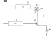
図1に示すように、負荷駆動システム1000は、駆動装置100と、ECU200と、通信バスB1と、第3信号線L3を、少なくとも備えている。本実施形態では、一例として、通信バスB1とは異なる第1信号線L1と第2信号線L2を備えた負荷駆動システム1000を採用している。
<Load drive system>
1, the
負荷駆動システム1000は、複数のアクチュエータ40nの駆動を制御する。負荷駆動システム1000のうち、駆動装置100は、バルブボディ上に配置されている。つまり、駆動装置100は、自動変速機と機電一体構造をなしている。ECU200は、自動変速機とは機械的に分離されている。なお、バルブボディを含む自動変速機に関しても負荷とみなすこともできる。図1では、アクチュエータ401~40nの通電経路を簡素化している。
The
なお、nは、2以上の自然数である。本実施形態では、一例として、n=8を採用している。よって、本実施形態では、第1アクチュエータ401~第8アクチュエータ408を通電駆動する例を採用している。また、本実施形態では、第1アクチュエータ401~第8アクチュエータ408の駆動を制御することで、自動変速機を1速~5速、Pレンジ、Rレンジ、Nレンジの間で切り替える例を採用している。
Note that n is a natural number equal to or greater than 2. In this embodiment, n=8 is used as an example. Therefore, in this embodiment, an example is used in which the
しかしながら、本開示は、これらに限定されない。本開示は、複数のアクチュエータ40nの駆動を制御することで、自動変速機の変速を1速~5速の間で切り替えるものであっても採用できる。また、本開示は、例えば、複数のアクチュエータ40nの駆動を制御することで、自動変速機をPレンジ、Rレンジ、Nレンジ、Dレンジの間で切り替えるものであっても採用できる。さらに、アクチュエータ40nとしては、オンオフソレノイドバルブであっても採用できる。
However, the present disclosure is not limited to these. The present disclosure can also be used to switch the automatic transmission between 1st to 5th gears by controlling the drive of
また、負荷駆動システム1000は、複数の駆動スイッチ301~30nを制御することで、複数のアクチュエータ40nの駆動を制御する。各駆動スイッチ301~30nは、各アクチュエータ40nの通電経路に個別に設けられている。よって、本実施形態では、一例として、第1駆動スイッチ301~第8駆動スイッチ308が設けられている例を採用する。駆動スイッチ301~308は、それぞれを特に区別する必要がない場合、駆動スイッチ30nとも称する。駆動スイッチ30nは、後ほど説明する駆動IC20に含まれていてもよい。
The
駆動スイッチ30nのオンにより、対応するアクチュエータ40nに対して電流の供給がされる。駆動スイッチ30nのオフにより、対応するアクチュエータ40nに対する電流の供給が遮断される。言い換えると、各アクチュエータ40nは、対応する駆動スイッチ30nがオンすることで通電される。また、各アクチュエータ40nは、対応する駆動スイッチ30nがオフすることで非通電とされる。
When the
図1、図2に示すように、負荷駆動システム1000は、給電スイッチ500(PSC)を備えている。また、負荷駆動システム1000は、各種センサを備えていてもよい。しかしながら、負荷駆動システム1000は、給電スイッチ500およびセンサを備えず、給電スイッチ500およびセンサが負荷駆動システム1000の外に配置された構成としてもよい。
As shown in Figures 1 and 2, the
給電スイッチ500は、アクチュエータ40nの通電経路に設けられている。複数のアクチュエータ40nに対して、単一(共通)の給電スイッチ500が設けられている。給電スイッチ500のオンにより、各アクチュエータ40nに対して電流の供給が可能となる。給電スイッチ500のオフにより、各アクチュエータ40nに対する電流の供給が遮断される。
The
給電スイッチ500は、複数のアクチュエータ40nに対して、ハイサイド側、すなわち電源側に配置されてもよいし、ローサイド側、すなわちグランド(GND)側に配置されてもよい。本実施形態の給電スイッチ500は、ハイサイド側に配置されている。なお、給電スイッチ500は、例えばMOSFETなどの半導体スイッチを採用できる。また、給電スイッチ500は、駆動装置100に設けられている。
The
センサは、負荷の状態を示す信号(電気信号)を出力する。センサは、バルブボディを含む自動変速機の状態を検出するともいえる。本実施形態では、センサの一例として、回転センサ600(RS)を備えている例を採用している。回転センサ600は、例えば自動変速機の入力側の回転数を示す信号を出力するセンサと、出力側の回転数を示す信号を出力するセンサを含む。
The sensor outputs a signal (electrical signal) indicating the state of the load. It can also be said that the sensor detects the state of the automatic transmission including the valve body. In this embodiment, an example equipped with a rotation sensor 600 (RS) is used as an example of a sensor. The
ECU200および駆動装置100は、共通の通信バスB1に接続されている。通信バスB1には、ECU200および駆動装置100とは別の図示しない装置が接続されてもよい。本実施形態において、ECU200および駆動装置100は、CANプロトコルに準拠した車載ネットワークの通信バスB1を介して、相互に通信可能に構成されている。言い換えると、ECU200および駆動装置100は、通信バスB1を介して、二線式差動方式によるデータの相互通信を行う。通信バスB1は、CANバスと称されることがある。CANは、Controller Area Networkの略称である。CANは、登録商標である。
The
このように、ECU200と駆動装置100は、通信バスB1としてCANバスを介して相互に通信を行う。このため、ECU200と駆動装置100は、実質的に一本の線で複数のデータを送受信できる。つまり、ECU200と駆動装置100は、三本以上の銅線を必要とするSPI通信などとは異なる方式で通信を行うものである。
In this way, the
本実施形態の負荷駆動システム1000において、ECU200および駆動装置100が送信するメッセージは、メッセージの重要度や種別などに応じて、予め優先順位が定められている。そして、各メッセージの送信に際しては、まず、各メッセージの優先順位を示す優先順位情報(IDコード)が送信される。このとき、複数のメッセージの優先順位情報の送信が競合した場合には、それぞれの優先順位情報の調停が行われ、より高い優先順位を持つ優先順位情報が送信権を獲得するようになっている。
In the
また、ECU200と駆動装置100は、第1信号線L1と第2信号線L2と第3信号線で接続されている。各信号線L1~L3は、CANバスとは異なり、上記メッセージを送受信するものではない。各信号線L1~L3は、SPI通信で用いられる銅線や、パラレル変換を行わないシリアル通信で用いられる銅線などである。よって、ECU200と駆動装置100は、後ほど説明するCANトランシーバ203などを介することなく、信号の送受信ができる。
The
ECU200と駆動装置100は、各信号線L1~L3を介してSPI通信を行う場合、シリアルデータを送受信し、受信したシリアルデータをパラレルデータに変換することで信号を取得する。また、ECU200と駆動装置100は、各信号線L1~L3を介してパラレル変換を行わないシリアル通信を行う場合、各信号線L1~L3が接続された端子のレベルを検出することで信号を取得する。
When the
第1信号線L1は、ECU200と給電回路70(PSC)とを接続している。第2信号線L2は、ECU200と第1比較器40(1CMP)とを接続している。第3信号線L3は、ECU200とCANコントローラ2(CTR)とを接続している。
The first signal line L1 connects the
<ECU>
ECU200は、負荷制御装置に相当する。つまり、ECU200は、駆動装置100の外部に設けられた制御装置である。ECU200は、第1マイコン201(MC)と、第2マイコン202(MC)を備えている。また、ECU200は、通信バスB1を介した通信を行うためのCANトランシーバ203(TRC)を備えている。
<ECU>
The
第1マイコン201は、CPU2011、CANコントローラ2012、ROM、RAM、レジスタなどを備えたマイクロコンピュータである。第1マイコン201において、CPU2011が、RAMやレジスタの一時記憶機能を利用しつつ、ROMに予め記憶された制御プログラムにしたがって各種制御を実行する。CPU2011は、ECU200外から取得したデータ、例えばセンサの検出信号を用いて制御を実行する。本実施形態のCPU2011は、各アクチュエータ40n、ひいては自動変速機の制御を実行する。
The
CPU2011は、自動変速機の変速段を設定する。CPU2011は、駆動装置100に対して変速段を指示する。CPU2011は、変速段を示す負荷駆動信号を示すデータ出力することで、駆動装置100に対して変速段を指示する。負荷駆動信号を示すデータは、負荷の駆動状態を指示する情報である。負荷駆動信号を示すデータは、駆動情報に相当する。以下、負荷駆動信号を示すデータを含むメッセージを駆動指示メッセージと称する。
The
駆動指示メッセージは、各アクチュエータ40nへの通電状態(駆動状態)を指示する信号(値)を含んでいる。つまり、駆動指示メッセージは、各アクチュエータ40nに個別に対応した通電状態を指示する信号を含んでいるともいえる。また、駆動指示メッセージは、各アクチュエータ40nの駆動状態を指示する信号を含んでいるともいえる。
The drive instruction message includes a signal (value) that indicates the energization state (drive state) of each
なお、CPU2011は、所定の演算を実行して目標電流値を設定してもよい。目標電流値は、各アクチュエータ40nを目標状態にするために、各アクチュエータ401~40nに流すべき電流値である。第1マイコン201は、自動変速機の状態を取得し、各アクチュエータ40nの出力油圧の必要値である目標油圧を算出する。第1マイコン201は、例えば自動変速機の入力側の回転数と出力側の回転数に基づいて、目標油圧を算出する。第1マイコン201は、算出した目標油圧に基づいて目標電流値を設定する。目標油圧と目標電流値との関係は、例えばマップや関数として予め定められている。ECU200は、駆動装置100に対して目標電流値を指示する。
The
CPU2011は、自動変速機の状態に基づいて、デューティ比を設定してもよい。第1マイコン201は、変速初期におけるオーバーシュートや、電流リプルなどの電流変動を抑制するために、デューティ比を設定する。デューティ比は、後述する駆動スイッチ30nのゲートに出力するPWM信号のデューティ比である。
The
第1マイコン201は、例えば油圧回路の作動油の圧力、作動油の温度、各アクチュエータ40nに流れる実電流値の少なくとも一つに基づいて、デューティ比を設定する。ECU200は、駆動装置100に対してデューティ比を指示する。ECU200は、ECU200の電源が投入されている期間においてデューティ比を指示してもよいし、変速初期など、一時的な期間のみにおいてデューティ比を指示してもよい。
The
CPU2011は、自動変速機の状態に基づいて、異常が生じているか否かを判定する。第1マイコン201は、例えば作動油の圧力と油圧閾値とを比較し、異常が生じているか否かを判定する。第1マイコン201は、例えば作動油の温度と温度閾値とを比較し、異常が生じているか否かを判定する。
The
異常が生じていると判定すると、ECU200は、すべてのアクチュエータ40nへの通電を所定の異常処置状態とするために、駆動装置100に対して緊急指示を出力する。本実施形態のECU200は、緊急指示として、すべてのアクチュエータ40nへの通電を遮断するために、駆動装置100に対して緊急遮断指示を出力する。なお、CPU2011は、駆動装置100から異常信号が入力された場合も緊急遮断指示を出力してもよい。この場合、CPU2011は、例えば第1信号線L1を介して異常信号が入力される。
When it is determined that an abnormality has occurred, the
ところで、後ほど説明するが、駆動装置100から異常信号が入力された場合、通信バスB1は、外部から攻撃されている可能性がある。つまり、通信バスB1を介して緊急遮断指示を送信した場合、緊急遮断指示は、改ざんされる可能性がある。このため、CPU2011は、CANトランシーバ203を介して緊急遮断指示を送信したとしても、駆動装置100が緊急遮断指示を受信できないことが起こりうる。
As will be explained later, when an abnormality signal is input from the
そこで、CPU2011は、CANトランシーバ203を介さずに、第1信号線L1を介して緊急遮断指示を出力すると好ましい。これによって、CPU2011は、駆動装置100に対して、確実に緊急遮断指示を出力できる。
Therefore, it is preferable for the
第1マイコン201は、通信バスB1を介したメッセージの送受信のために、CANコントローラ2012を内蔵している。CANコントローラ2012は、CANプロトコルにしたがった通信制御を実行する。CANコントローラ2012は、例えば、送信制御、受信制御、および調停制御を実行する。
The
CANトランシーバ203は、CANコントローラ2012に電気的に接続されるとともに、通信バスB1にも電気的に接続されている。CANトランシーバ203は、通信バスB1とCANコントローラ2012との間の電気的特性を相互変換することにより、通信バスB1とCANコントローラ2012との間を双方向へメッセージを伝達可能にしている。例えば、通信バスB1のバスレベルの信号をCANコントローラ2012が取り扱い可能なデジタル信号に変換することで、ドミナントとレセシブとを認識できるようにする。つまり、CANコントローラ2012は、CANトランシーバ203を介して通信バスB1に接続されることで通信バスB1との間でのメッセージの送受信が可能になっている。
The
CANコントローラ2012は、メッセージを格納するメッセージボックスを有している。CANコントローラ2012は、送信用のメッセージボックスと、受信用のメッセージボックスを有している。CANコントローラ2012は、通信インターフェースを介して取得した送信用のメッセージを、メッセージボックスに順次格納する。CANコントローラ2012は、格納されたメッセージを、IDコードの優先順位に応じて送信処理する。CANコントローラ2012は、メッセージボックスに格納されたメッセージに基づいてフレームを生成し、CANトランシーバ203を介して通信バスB1に送信する。
The
CPU2011は、例えば、駆動指示メッセージをCANコントローラ2012の送信用メッセージボックスに格納する。この場合、CANコントローラ2012は、駆動指示メッセージを含むフレームを生成して、CANトランシーバ203を介して通信バスB1に送信する。なお、CANコントローラ2012は、データフィールドに駆動指示メッセージを含むフレームを生成することになる。このように、駆動指示メッセージは、フレームのデータフィールドに配置されて送信される。よって、駆動指示メッセージは、CANメッセージデータの一つである。
For example, the
CANコントローラ2012は、CANトランシーバ203を介して通信バスB1からフレームを受信してメッセージ等を抽出し、メッセージボックスに順次格納する。CANコントローラ2012は、IDコードの優先順位にしたがって受信したメッセージを送信対象に出力する。CANコントローラ2012は、通信バスB1上でフレームが衝突した際の送信権の調停(ビット単位非破壊アービトレーション)を行う。CANコントローラ2012は、その他、フレームの送受信に関連して生じるエラーの検出、通知等を行う。CANトランシーバ203およびCANコントローラ2012は、制御側通信部といえる。
The
ECU200は、図1に示すように第2マイコン202をさらに備えてもよい。第2マイコン202は、第1マイコン201が正常に動作しているかを監視する。第1マイコン201はメインマイコンと称され、第2マイコン202は監視マイコンと称されることがある。第2マイコン202は、例えば第1マイコン201にウォッチドック異常、通信異常、演算機能の異常がないか監視する。第2マイコン202は、上記した監視機能に加えて、第1マイコン201が実行する制御を補助する機能を有してもよい。第2マイコン202は、負荷駆動システム1000とは別の制御を実行してもよい。第2マイコン202についても、図示しないCANコントローラを内蔵し、通信バスB1を介してメッセージを送受信可能な構成としてもよい。
The
本実施形態では、第1マイコン201の監視手段が第2マイコン202として構成されており、マイコン201、202は、それぞれが正常に動作しているか相互に監視する。第1マイコン201の監視手段は、第2マイコン202に限定されない。第2マイコン202に代えて、監視ICを設けてもよい。ECU200が、第2マイコン202などの監視手段を備えない構成としてもよい。
In this embodiment, the monitoring means of the
<駆動装置構成>
駆動装置100に関して説明する。図2では、便宜上、一つのアクチュエータ401に対応する箇所のみを図示している。
<Drive unit configuration>
The
駆動装置100は、負荷駆動装置に相当する。駆動装置100は、複数のアクチュエータ40nを通電駆動する回路である。また、駆動装置100は、複数の駆動スイッチ30nを制御することで、複数のアクチュエータ40nを通電駆動する。駆動装置100は、ECU200と異なり、マイコンを備えていない。つまり、駆動装置100は、ハードウェアロジックによって、複数のアクチュエータ40nを通電駆動する。
The
駆動装置100は、主に、CANトランシーバ1、CANコントローラ2、制御レジスタ11を含むSPI回路10、駆動IC20、第1比較器40、ROM50を備えている。さらに、駆動装置100は、シーケンス回路30、レジスタ部60、給電回路70、電流検出抵抗81、増幅器82、第2比較器83、モニタレジスタ84、波形解析回路90などを備えている。
The
CANトランシーバ1は、CANコントローラ2に電気的に接続されるとともに、通信バスB1にも電気的に接続されている。CANトランシーバ1は、通信バスB1とCANコントローラ2との間の電気的特性を相互変換することにより、通信バスB1とCANコントローラ2との間を双方向へメッセージを伝達可能にしている。CANコントローラ2は、CANトランシーバ1を介して通信バスB1に接続されることで通信バスB1との間でのメッセージの送受信が可能になっている。
The
CANコントローラ2は、メッセージを格納するメッセージボックスを有している。CANコントローラ2は、送信用のメッセージボックスと、受信用のメッセージボックスを有している。CANコントローラ2は、通信インターフェースを介して取得した送信用のメッセージを、メッセージボックスに順次格納する。CANコントローラ2は、格納されたメッセージを、IDコードの優先順位に応じて送信処理する。CANコントローラ2は、メッセージボックスに格納されたメッセージに基づいてフレームを生成し、CANトランシーバ1を介して通信バスB1に送信する。
The
CANコントローラ2は、CANトランシーバ1を介して通信バスB1からフレームを受信してメッセージボックスに順次格納する。CANコントローラ2は、IDコードの優先順位にしたがって受信したメッセージを送信対象に出力する。CANコントローラ2は、通信バスB1上でフレームが衝突した際の送信権の調停(ビット単位非破壊アービトレーション)を行う。CANコントローラ2は、その他、フレームの送受信に関連して生じるエラーの検出、通知等を行う。
The
詳述すると、CANコントローラ2は、例えば、駆動指示メッセージを含むフレームを受信した場合、フレームにおけるデータフィールドのデータを受信用のメッセージボックスに格納する。また、CANコントローラ2は、受信用のメッセージボックスからデータを取り出す。そして、CANコントローラ2は、取り出したデータから駆動指示メッセージを抽出して、駆動指示メッセージを負荷駆動信号に変換する。負荷駆動信号は、駆動情報、または、駆動情報に相当する信号といえる。
In more detail, when the
なお、CANコントローラ2は、SPI通信用のレジスタを有していてもよい。この場合、CANコントローラ2は、駆動指示メッセージを、メッセージボックスからレジスタなどに格納してもよい。このように、CANコントローラ2は、ECU200から送信された駆動指示メッセージを一時的に記憶する。
The
CANコントローラ2に記憶された負荷駆動信号は、例えば、通電を指示する信号として1、非通電を指示する信号として0を含んでいる。よって、負荷駆動信号は、0と1によって表すことができる。本実施形態では、図3の上段に示すように、一例として8ビットの負荷駆動信号を採用する。しかしながら、本開示は、これに限定されず、複数ビットの負荷駆動信号であれば採用できる。
The load drive signal stored in the
負荷駆動信号は、複数のアクチュエータ40nの駆動を制御する信号である。このため、CANコントローラ2に記憶された負荷駆動信号は、制御パターンといえる。また、CANコントローラ2に記憶された制御パターンは、複数のアクチュエータ40nの駆動を制御する今回の制御パターンである。よって、CANコントローラ2に記憶された制御パターンは、制御パターンの更新値といえる。
The load drive signal is a signal that controls the drive of the
また、制御パターンの更新値は、各アクチュエータ40nの駆動遷移後の駆動状態(次回駆動状態)に対応している。このため、各アクチュエータ40nは、制御パターンが前回値から更新値に切り替わることで駆動状態が遷移する。制御パターンの前回値に関しては、後ほど詳しく説明する。
The updated value of the control pattern corresponds to the drive state (next drive state) of each
なお、図3の上段に示すように、本実施形態では、一例として、制御パターンの更新値として11100100(1速)が書き込まれた状態のCANコントローラ2を採用している。また、制御パターンの更新値は、遷移判定値としての遷移禁止パターン52と比較される。よって、制御パターンは、比較パターンともいえる。また、遷移禁止パターン52は、判定用パターンともいえる。
As shown in the upper part of FIG. 3, in this embodiment, as an example, a
なお、図3の上段における第1ビット211は、第1アクチュエータ401に対応している。第2ビット212は、第2アクチュエータ402に対応している。第3ビット213は、第3アクチュエータ403に対応している。第4ビット214は、第4アクチュエータ404に対応している。第5ビット215は、第5アクチュエータ405に対応している。第6ビット216は、第6アクチュエータ406に対応している。第7ビット217は、第7アクチュエータ407に対応している。第8ビット218は、第8アクチュエータ408に対応している。
Note that the
なお、本実施形態では、CANトランシーバ1およびCANコントローラ2で受信された負荷駆動信号に相関する各アクチュエータ40nの相関駆動状態として、制御パターンの更新値そのものを採用している。相関駆動状態は、駆動遷移後の駆動状態とみなすことができる。よって、相関駆動状態は、次駆動状態ともいえる。
In this embodiment, the updated value of the control pattern itself is used as the correlated drive state of each
また、CANコントローラ2は、制御パターンの更新値をSPI回路10に出力する。このとき、CANコントローラ2は、制御パターンの更新値が正常な場合に限って、SPI回路10に出力する。つまり、CANコントローラ2は、後ほど説明する第1比較器40から正常信号が出力されると、制御パターンの更新値をSPI回路10に出力する。また、CANコントローラ2は、第1比較器40から異常信号が出力されると、制御パターンの今回値をSPI回路10に出力することなく破棄する。
The
SPI回路10(SPIC)は、CANコントローラ2、駆動IC20、シーケンス回路30などと接続されている。SPI回路10は、制御レジスタ11(CREG)を有している。なお、制御レジスタ11は、制御用記憶部といえる。SPIは、Serial Peripheral Interfaceの略称である。
The SPI circuit 10 (SPIC) is connected to the
制御レジスタ11は、CANコントローラ2から出力された制御パターンが記憶される。後ほど説明するが、駆動装置100は、制御レジスタ11に記憶されている制御パターンに応じて駆動IC20が各アクチュエータ40nの駆動を制御する。そして、制御レジスタ11には、駆動IC20が駆動制御に用いた制御パターンが記憶されているといえる。よって、制御レジスタ11に記憶されている制御パターンは、制御パターンの前回値といえる。つまり、制御パターンの前回値は、各アクチュエータ40nの現在の駆動状態である現駆動状態に対応している。このように、SPI回路10は、制御パターンの前回値を取得する。
The control register 11 stores the control pattern output from the
なお、図3の下段に示すように、本実施形態では、一例として、制御パターンの前回値として01110100(4速)が書き込まれた状態の制御レジスタ11を採用している。制御レジスタ11は、各アクチュエータ40nに対応したアドレスのビット111~118を有している。制御レジスタ11は、負荷駆動信号における各アクチュエータ40nへの駆動状態を指示する信号が、各アドレスのビットに書き込まれる。
As shown in the lower part of Figure 3, this embodiment employs, as an example, a
図3の下段における第1ビット111は、第1アクチュエータ401に対応している。第2ビット112は、第2アクチュエータ402に対応している。第3ビット113は、第3アクチュエータ403に対応している。第4ビット114は、第4アクチュエータ404に対応している。第5ビット115は、第5アクチュエータ405に対応している。第6ビット116は、第6アクチュエータ406に対応している。第7ビット117は、第7アクチュエータ407に対応している。第8ビット118は、第8アクチュエータ408に対応している。
The
図1、図2に示すように、駆動IC20は、複数の駆動スイッチ30nと接続されている。駆動IC20は、制御パターンに応じて複数の駆動スイッチ30nを制御する。つまり、駆動IC20は、制御レジスタ11に格納されている制御パターンに応じて、各駆動スイッチ30nを個別にオンオフさせる駆動信号を出力する。また、駆動IC20は、制御レジスタ11に格納されている制御パターンに応じて、複数の駆動スイッチ301~308を選択的にオンオフする。
As shown in Figures 1 and 2, the driving
なお、図1では、便宜的に、駆動IC20を一つのみ図示している。しかしながら、駆動装置100は、各駆動スイッチ30nのそれぞれと個別に接続された複数の駆動IC20を備えている。つまり、駆動装置100は、駆動スイッチ30nの個数と同数の駆動IC20を備えている。
For convenience, only one driving
よって、各駆動IC20は、制御パターンにおける自身に対応する値に応じて、自身に接続されている駆動スイッチ30nをオンオフする。例えば、第1の駆動IC20と第1駆動スイッチ301が接続されていた場合、第1の駆動IC20は、制御レジスタ11の第1ビット111に格納されている値に応じて、第1駆動スイッチ301をオンオフする。
Therefore, each driving
駆動信号としては、PWM信号を採用できる。この場合、駆動IC20は、PWM信号のデューティ比を変えることにより、アクチュエータ40nに流す電流(すなわち、通電電流)を変えることができる。PWMは、Pulse Width Modulationの略である。
A PWM signal can be used as the drive signal. In this case, the
例えば制御パターンが11100100の場合、駆動IC20は、第1駆動スイッチ301~第3駆動スイッチ303、第6駆動スイッチ306をオンする。これによって、駆動IC20は、第1アクチュエータ401~第3アクチュエータ403、第6アクチュエータ406に通電する。また、このとき、駆動IC20は、第4駆動スイッチ304、第5駆動スイッチ305、第7駆動スイッチ307、第8駆動スイッチ308をオフする。これによって、駆動IC20は、第4アクチュエータ404、第5アクチュエータ405、第7アクチュエータ407、第8アクチュエータ408を非通電とする。
For example, when the control pattern is 11100100, the driving
図4に示すように、シーケンス回路30(SQC)は、第1データローダ31と第2データローダ32と第3データローダ33と第4データローダ34と第3比較器41などを備えている。また、シーケンス回路30は、複数のスイッチング素子などを備えている。シーケンス回路30は、クロックに同期して動作する。シーケンス回路30は、制御パターンの更新値と判定用パターンとを比較するために動作する。
As shown in FIG. 4, the sequence circuit 30 (SQC) includes a
第1データローダ31は、図5に示すように、CANコントローラ2に記憶されている制御パターンの更新値を第1データレジスタ61に書き込む。つまり、第1データローダ31は、CANコントローラ2における各ビットの信号をコピーして第1データレジスタ61の各ビットに書き込む。
As shown in FIG. 5, the
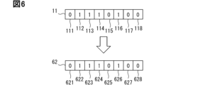
第2データローダ32は、図6に示すように、制御レジスタ11に記憶されている制御パターンの前回値を第2データレジスタ62に書き込む。つまり、第2データローダ32は、制御レジスタ11における各ビットの信号をコピーして第2データレジスタ62の各ビットに書き込む。
As shown in FIG. 6, the
第3データローダ33は、図7に示すように、ROM50の記憶されている複数の通電パターン51を順番に第3データレジスタ63に書き込む。つまり、第3データローダ33は、通電パターン51における各ビットの信号をコピーして第3データレジスタ63の各ビットに書き込む。なお、通電パターン51に関しては、後ほど詳しく説明する。
As shown in FIG. 7, the third data loader 33 writes the
第3比較器41は、第2データレジスタ62にセットされた制御パターンと、第3データレジスタ63にセットされた通電パターン51とを順番に比較する。第3比較器41は、複数の通電パターン51から制御パターンの前回値に一致する通電パターン51を選択する。これは、制御パターンの前回値に対応する遷移禁止パターン52を選択するためである。第3比較器41は、制御パターンの前回値に一致する通電パターン51を示す信号を出力する。
The
なお、第3比較器41は、制御パターンの前回値が4速を示す制御パターンであることを検出するともいえる。また、第3比較器41は、制御パターンの前回値が示す駆動状態から、制御パターンの更新値が示す駆動状態への駆動遷移を判定するともいえる。
The
第4データローダ34は、図8に示すように、ROM50に記憶されている遷移禁止パターン52を第4データレジスタ64に書き込む。第4データローダ34は、第3比較器41から出力された信号に対応する遷移禁止パターン52を第4データレジスタ64に書き込む。遷移禁止パターン52が複数ある場合、第4データローダ34は、遷移禁止パターン52を順番に第4データレジスタ64に書き込む。つまり、第4データローダ34は、遷移禁止パターン52における各ビットの信号をコピーして第4データレジスタ64の各ビットに書き込む。このように、第4データローダ34は、制御パターンに関連付けられた遷移禁止パターン52をROM50から取得する。
As shown in FIG. 8, the
本実施形態では、判定用パターンとして遷移禁止パターン52を採用している。なお、遷移禁止パターン52は、遷移判定値および禁止判定値といえる。遷移禁止パターン52に関しては、後ほど詳しく説明する。
In this embodiment, a
第1比較器40(1CMP)は、オペアンプなどによって構成されている。第1比較器40は、遷移禁止パターン52と、制御パターンの更新値とを比較する。第1比較器40は、遷移禁止パターン52の各信号と制御パターンの更新値における各信号を順番に比較する。第1比較器40は、遷移禁止パターン52と制御パターンの更新値とを比較して、遷移禁止パターン52と制御パターンの更新値とが所定の対応関係を満たしているか否かを判定する。そして、第1比較器40は、所定の対応関係を満たしている場合に制御パターンの更新値が異常と判定する。
The first comparator 40 (1CMP) is composed of an operational amplifier and the like. The
このように、本実施形態では、遷移判定値として遷移禁止パターン52を採用している。よって、第1比較器40は、遷移禁止パターン52と制御パターンの更新値とが一致していた場合に、所定の対応関係を満たしていると判定する。また、遷移禁止パターン52と制御パターンの更新値とが一致している状態は、制御パターンの更新値が遷移禁止パターン52に含まれるともいえる。一方、第1比較器40は、遷移禁止パターン52と制御パターンの更新値とが不一致の場合に、所定の対応関係を満たしていないと判定する。
In this manner, in this embodiment, the
遷移禁止パターン52と一致した制御パターンの更新値は、現駆動状態から禁止されている駆動状態への駆動遷移を指示する制御パターンとなる。このため、この制御パターンの更新値は、異常な制御パターンである。CANコントローラ2が異常な制御パターンを受信する原因は、メッセージのなりすましなどをあげることができる。つまり、負荷駆動システム1000は、例えば通信バスB1が攻撃されて負荷駆動信号が改ざんされることで、異常な制御パターンが駆動装置100に送信されてしまう。
The updated value of the control pattern that matches the
一方、遷移禁止パターン52と一致していない制御パターンの更新値は、現駆動状態から禁止されていない駆動状態への駆動遷移を指示する制御パターンとなる。このため、この制御パターンの更新値は、正常な制御パターンである。
On the other hand, the update value of a control pattern that does not match the
よって、第1比較器40は、遷移禁止パターン52と制御パターンの更新値とが一致した場合、制御パターンの更新値が異常と判定する。一方、第1比較器40は、遷移禁止パターン52と制御パターンの更新値とが一致しなかった場合、制御パターンの更新値が正常と判定する。
Therefore, when the
また、第1比較器40は、一致した場合と不一致の場合とで出力信号が異なる。第1比較器40は、一致した場合、制御パターンの更新値が異常であることを示す異常信号を出力する。異常信号は、制御パターンの更新値が異常であることを示すとともに、通信バスB1を介した通信が異常であること示している。
The
一方、第1比較器40は、一致しなかった場合、制御パターンが正常であることを示す正常信号を出力する。異常信号および正常信号は、CANコントローラ2、給電回路70、ECU200などに出力される。正常信号は、制御パターンの更新値が正常であることを示すとともに、通信バスB1を介した通信が正常であること示している。
On the other hand, if there is no match, the
第1比較器40は、異常信号をCANコントローラ2に出力することで、制御パターンの更新値が異常であることをCANコントローラ2に通知する。第1比較器40は、CANコントローラ2に異常を通知することで、制御パターンの更新値の破棄をCANコントローラ2に指示する。第1比較器40は、異常信号を給電回路70やECU200に出力することで、アクチュエータ40nに対する電源状態を遮断状態とすることを指示する。なお、電源のカットを指示する場合、第1比較器40は、給電回路70やECU200の少なくとも一方に異常信号を出力すればよい。
The
また、第1比較器40は、正常信号をCANコントローラ2に出力することで、制御パターンの更新値の出力をCANコントローラ2に指示する。第1比較器40は、正常信号を給電回路70やECU200に出力することで、アクチュエータ40nに対する電源状態を給電状態とすることを指示する。
The
上記のように、通信バスB1は、外部から攻撃されることがありうる。つまり、通信バスB1を介して異常信号や正常信号を送信した場合、それらの信号は、が改ざんされる可能性がある。このため、駆動装置100は、CANトランシーバ203を介して異常信号や正常信号を送信したとしても、それらの信号をECU200が受信できないことが起こりうる。
As described above, the communication bus B1 may be attacked from the outside. In other words, if an abnormal signal or normal signal is transmitted via the communication bus B1, there is a possibility that the signal may be tampered with. For this reason, even if the
そこで、第1比較器40は、第2信号線L2を介して、ECU200に異常信号や正常信号を出力すると好ましい。これによって、第1比較器40は、通信バスB1が攻撃されていたとしても、異常信号や正常信号をECU200に出力できる。
Therefore, it is preferable that the
ROM50は、通電パターン51(EZP)と遷移禁止パターン52(PHP)が記憶されている。ROM50は、通電パターン51が記憶された通電パターンメモリと、遷移禁止パターン52が記憶された遷移禁止パターンメモリとを有しているともいえる。ROM50は、判定用記憶部といえる。
The
図9に示すように、通電パターン51は、各アクチュエータ40nへの駆動状態として取りうる全駆動状態のそれぞれに対応した制御パターンである。よって、ROM50は、複数の通電パターン51を記憶している。また、各通電パターン51は、各アクチュエータ40nの駆動状態を指示する信号を含むものである。さらに、各通電パターン51は、自動変速機の各状態に相関するものである。制御パターンの前回値と制御パターンの更新値は、正常であれば、通電パターン51の一つとなる。なお、図9などでは、各アクチュエータ401~408をACT1~ACT8と示している。
As shown in FIG. 9, the
図10に示すように、遷移禁止パターン52は、各アクチュエータ40nへの駆動状態を示す通電パターン51である。遷移禁止パターン52は、現駆動状態からの駆動遷移に相関する値である。遷移禁止パターン52は、制御パターンの更新値が異常であるか否かを判定するための判定値である。ROM50は、制御パターンと遷移禁止パターン52とが関連付けられて記憶されている。
As shown in FIG. 10, the
遷移禁止パターン52は、制御パターンの前回値が示す駆動状態からの駆動遷移が禁止されている駆動状態を示すものである。遷移禁止パターン52は、自動変速機として好ましくない動作となる駆動遷移を示す通電パターン51といえる。
The
図10の例では、一例として、4速を示す制御パターンに関連付けられた遷移禁止パターン52を示している。自動変速機が4速の場合、1速へのシフトダウンは、意図しない急減速になる。また、Rレンジへのシフトチェンジは、意図しない逆速になる。そして、Pレンジへのシフトチェンジは、意図しないPロックになる。このため、4速に対応する制御パターンには、1速、Rレンジ、Pレンジのそれぞれに対応する通電パターンが遷移禁止パターンとして関連付けられている。遷移禁止パターン52は、制御パターンとは異なり、予めROM50に記憶されている。
In the example of FIG. 10, a
ROM50は、各アクチュエータ401~408に対応したアドレスのビットを有している。ROM50は、遷移禁止パターン52における各アクチュエータ401~408への駆動状態を示す信号(値)が、各アドレスのビットに書き込まれている。本実施形態では、一例として、8ビットの制御パターンを採用している。よって、各遷移禁止パターン52は、制御パターンと同じ8ビットとなる。各遷移禁止パターン52は、通電を示す信号として1、非通電を示す信号として0を含んでいる。よって、各遷移禁止パターン52は、0と1によって表すことができる。
The
ROM50は、CANコントローラ2を介してアクセスできない構成であると好ましい。つまり、ROM50は、CANコントローラ2を介して、駆動装置100の外部から書換ができない構成である。また、ROM50は、通信バスB1を介した通信とは独立して設けられているといえる。よって、ROM50は、工場やディーラなどで通電パターン51や遷移禁止パターン52が書き込まれる。このようにすることで、駆動装置100は、通電パターン51や遷移禁止パターン52が意図せず書き換えられることを抑制できる。
It is preferable that the
レジスタ部60(REG)は、第1データレジスタ61(1REG)、第2データレジスタ62(2REG)、第3データレジスタ63(3REG)、第4データレジスタ64(4REG)を備えている。各データレジスタ61~64には、上記のように値がセットされる。 The register section 60 (REG) includes a first data register 61 (1REG), a second data register 62 (2REG), a third data register 63 (3REG), and a fourth data register 64 (4REG). Values are set in each of the data registers 61 to 64 as described above.
図1、図2に示すように、給電回路70は、給電スイッチ500のオンオフを切り替える回路である。給電回路70は、給電スイッチ500のオンオフによって、複数のアクチュエータ401~408への電源状態を切り替える。給電回路70(PSC)は、電源部といえる。
As shown in Figures 1 and 2, the
給電回路70は、例えば、ECU200から緊急遮断指示が入力されると、給電スイッチ500のオフを示す信号を出力する。つまり、給電回路70は、給電スイッチ500をオフして、各アクチュエータ40nに対する電源状態を遮断状態にする。また、給電回路70は、異常な制御パターンによって各アクチュエータ40nが駆動されることを防止するために、給電スイッチ500をオフするともいえる。一方、給電回路70は、制御パターンの更新値が正常の場合、給電スイッチ500をオンして、各アクチュエータ40nに対する電源状態を給電状態とする。
When an emergency shutoff command is input from the
なお、給電回路70は、第1比較器40から異常信号が入力された場合に、給電スイッチ500のオフを示す信号を出力してもよい。緊急遮断指示および異常信号は、給電スイッチ500のオフを指示する信号ともいえる。
In addition, the
電流検出抵抗81は、増幅器82とともに電流検出部を構成している。電流検出部は、各アクチュエータ40nに個別に設けられている。よって、本実施形態では、五つの電流検出部が駆動装置100に設けられている。図1では、代表例として、第1アクチュエータ401に対応する電流検出部のみを図示している。
The
各電流検出部は、対応するアクチュエータ40nに実際に流れる電流を検出する。言い換えると、各電流検出部は、対応するアクチュエータ40nの駆動状態を検出する。また、各電流検出部は、各アクチュエータ40nへの通電状態をモニタするともいえる。
Each current detection unit detects the current that actually flows through the corresponding
なお、電流検出部は、電流検出抵抗81と増幅器82に加えて、増幅器82で増幅された電圧のノイズを除去するフィルタを備えていてもよい。フィルタは、例えば抵抗とコンデンサで構成することができる。
In addition to the
電流検出抵抗81は、アクチュエータ401に直列に接続されている。電流検出抵抗81は、第1アクチュエータ401に対してグランド側(下流側)に設けられている。増幅器82は、電流検出抵抗81の両端に生じ、電流に比例する電圧を増幅する。よって、増幅器82は、第1アクチュエータ401に流れる電流に比例した電圧信号を出力する。このため、各電流検出部は、対応する各アクチュエータ40nに流れる電流に比例した電圧信号を出力する。
The
第2比較器83(2CMP)は、オペアンプなどによって構成されている。第2比較器83は、各アクチュエータ40nに個別に設けられている。また、第2比較器83は、電流検出抵抗81および増幅器82とセットで設けられている。本実施形態では、八つの第2比較器83が駆動装置100に設けられている。図1では、代表例として、第1アクチュエータ401に対応する第2比較器83のみを図示している。
The second comparator 83 (2CMP) is composed of an operational amplifier or the like. The
第2比較器83は、増幅器82が出力する電圧信号と基準値とを比較する。第2比較器82は、電圧信号が基準値よりも高ければ正の値を出力し、電圧信号が基準値よりも低ければ負の値を出力する。つまり、第2比較器83は、各電流検出部がモニタした各アクチュエータ40nへの通電状態を示すモニタ結果を出力するともいえる。第2比較器83は、例えば、第1アクチュエータ401が通電されている場合は正の値を出力する。また、第2比較器83は、例えば、第1アクチュエータ401が通電されていない場合は負の値を出力する。
The
図11に示すように、モニタレジスタ84(MREG)は、各第2比較器83の出力が書き込まれる。つまり、モニタレジスタ84には、各アクチュエータ40nへの通電状態をモニタした結果であるモニタパターンが記憶されるといえる。モニタパターンは、現駆動状態とみなせる。また、モニタパターンは、相関駆動状態とみなすこともできる。モニタレジスタ84は、モニタ用記憶部ともいえる。図11では、一例として、4速を示すモニタパターンが記憶されたモニタレジスタ84を採用している。
As shown in FIG. 11, the output of each
このように、駆動装置100は、電流検出抵抗81、増幅器82、第2比較器83、モニタレジスタ84によって、各アクチュエータ40nの現駆動状態を取得することができる。本実施形態は、現駆動状態として、制御パターンの前回値のかわりに、モニタパターンを用いることもできる。これらの構成要素81~84は、取得装置といえる。しかしながら、本開示は、構成要素81~84を備えていなくてもよい。特に、モニタレジスタ84は、設けられていなくてもよい。
In this way, the driving
モニタレジスタ84は、各アクチュエータ401~408に対応したアドレスのビットを有している。モニタレジスタ84は、各アクチュエータ401~408への通電状態を示す信号(値)が、各アドレスのビットに書き込まれる。各アクチュエータ401~408への通電状態を示す信号は、各第2比較器83の出力である。
The
モニタレジスタ84には、例えば、通電を示す信号として1、非通電を示す信号として0が書き込まれる。よって、モニタパターンは、0と1によって表すことができる。本実施形態では、一例として、8ビットの制御パターンを採用している。よって、モニタパターンは、制御パターンと同じ8ビットとなる。
For example, a signal of 1 indicating power is applied and a signal of 0 indicating power is not applied are written to the
なお、モニタレジスタ84の第1ビット841は、第1アクチュエータ401に対応している。同様に、第2ビット842~第8ビット848のそれぞれは、第2アクチュエータ402~第8アクチュエータ408のそれぞれに対応している。
Note that the
波形解析回路90は、回転センサ600の出力である回転センサ信号が入力される。波形解析回路90は、回転センサ信号[pls/s]に基づいて車速を判定する。波形解析回路90は、例えば、車速が高速、低速、0(停車)のいずれであるかを判定する。
The
波形解析回路90は、回転センサ信号が予め決められた閾値に達した場合に高速と判定する。また、波形解析回路90は、回転センサ信号が予め決められた閾値に達しておらず、かつ、0でない場合に低速と判定する。そして、波形解析回路90は、回転センサ信号が0の場合に停車と判定する。
The
よって、車速は、各アクチュエータ40nの現駆動状態とみなせる。よって、波形解析回路90は、取得装置といえる。しかしながら、本開示は、波形解析回路90を備えていなくてもよい。なお、回転センサ600は、負荷の駆動状態に応じた電気信号を出力するセンサである。
Therefore, the vehicle speed can be regarded as the current driving state of each
また、本実施形態では、負荷の駆動状態に応じた電気信号を出力するセンサ一例として、回転センサ600を採用している。しかしながら、本開示は、これに限定されない。本実施形態は、後ほどの実施形態と同様、油圧センサ、油温センサ、Pロックセンサなどであっても採用できる。つまり、駆動装置100は、油圧センサ、油温センサ、Pロックセンサが接続されていてもよい。
In addition, in this embodiment, a
この場合、駆動装置100は、各センサから出力された電気信号を、通信バスB1を介してECU200に送信するしてもよい。これによって、負荷駆動システム1000は、信号線の数が増えることを抑制できる。この結果、負荷駆動システム1000は、安価に構成することができる。
In this case, the
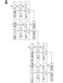
<処理動作>
図12~図15を用いて、負荷駆動システム1000の処理動作に関して説明する。
<Processing Operation>
The processing operation of the
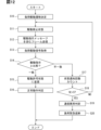
まず、図12を用いて、ECU200の処理動作に関して説明する。ECU200は、所定時間ごと、またはイベント発生時に、図12のフローチャートに示す処理動作を開始する。
First, the processing operation of the
ステップS10では、負荷駆動遷移を決定する。CPU2011は、駆動装置100に指示する負荷駆動信号を決定することで、負荷駆動遷移を決定する。CPU2011は、例えば、自動変速機の変速を1速へと切り替えることを示す負荷駆動遷移を決定する。
In step S10, the load drive transition is determined. The
ステップS11では、駆動禁止状態とする(駆動許可部)。CPU2011は、負荷を駆動禁止の状態とする。CPU2011は、負荷駆動遷移を決定したとしても、ステップS14で一致と判定するまでは負荷を正常に駆動できない可能性がある。このため、CPU2011は、ステップS14で一致と判定するまでの間は、負荷を駆動禁止の状態とする。言い換えると、CPU2011は、負荷を異常に駆動する状態でないと判定するまで、負荷を駆動禁止とする。なお、駆動禁止状態とは、駆動装置100による負荷の駆動が禁止されている状態である。
In step S11, a drive prohibition state is set (drive permission unit). The
例えば、CPU2011は、負荷の駆動許可を示す駆動許可信号を駆動装置100に出力することで負荷の駆動禁止を解除、すなわち、負荷を駆動許可の状態とする。一方、CPU2011は、駆動許可信号を駆動装置100に出力しないことで負荷を駆動禁止の状態とする。
For example, the
CPU2011は、第3信号線L3を介してCANコントローラ2に駆動許可信号を出力する。そして、CANコントローラ2は、駆動許可信号が入力されている場合に限って、制御パターンの更新値をSPI回路10に出力する。よって、駆動装置100は、駆動許可信号が入力されている場合に限って負荷の駆動が可能となる。
The
ステップS12では、駆動指示メッセージを含むフレームを送信する(送信部)。CPU2011は、ステップS11で決定した負荷駆動信号に対応する駆動指示メッセージをCANコントローラ2012の送信用のメッセージボックスに格納する。CANコントローラ2012は、駆動指示メッセージを含むフレームを生成して、CANトランシーバ203を介して通信バスB1に送信する。ここでは、1速への切り替え指示を示す駆動指示メッセージを含むフレームを、通信バスB1を介して駆動装置100に送信する。なお、CPU2011は、負荷の駆動状態を指示する駆動情報を含む複数のメッセージを、通信バスB1を介して駆動装置100に送信する。
In step S12, a frame including a drive instruction message is transmitted (transmitting unit). The
ステップS13では、負荷駆動信号を取得する(取得部)。CPU2011は、第3信号線L3を介して負荷駆動信号を取得する。つまり、CPU2011は、駆動装置100から負荷駆動信号を取得する。
In step S13, the load drive signal is acquired (acquisition unit). The
CPU2011は、駆動装置100に対して指示した駆動状態と、駆動装置100が実行しようとしている駆動状態とが一致するか否かを判定するために、負荷駆動信号を取得する。また、CPU2011は、駆動装置100が指示された駆動状態通りに、負荷を駆動するか否かを判定するために負荷駆動信号を取得するといえる。さらに、CPU2011は、駆動装置100に対して送信した駆動指示メッセージが改ざんされているか否かを判定するために負荷駆動信号を取得するといえる。
The
ステップS14では、駆動指示と比較する(比較部)。CPU2011は、ステップS12で送信した駆動指示メッセージと、ステップS13で受信した負荷駆動信号とを比較する。つまり、CPU2011は、ECU200が通信バスB1を介して送信した駆動情報と、第3信号線L3を介して駆動装置100から送信されてECU200が取得した駆動情報とを比較するといえる。また、ECU200は、駆動装置100に指示した駆動状態と、駆動装置100がECU200から指示された駆動状態とを比較するともいえる。例えば、CPU2011は、駆動装置100と同様に、送信した駆動指示メッセージを負荷駆動信号に変換して、受信した負荷駆動信号と比較することができる。
In step S14, it is compared with the drive instruction (comparison section).
後ほど説明するが、駆動装置100は、ECU200から送信された駆動指示メッセージを受信すると、その駆動指示メッセージを負荷駆動信号へと変換する。そして、駆動装置100は、変換した負荷駆動信号をECU200に通知する。このため、ステップS13で受信した負荷駆動信号は、改ざんなどされていなければ、ステップS12で送信した駆動指示メッセージと一致している。
As will be explained later, when the
そこで、CPU2011は、ステップS12で送信した駆動指示メッセージと、ステップS13で受信した負荷駆動信号とが一致していると判定した場合、ステップS15へ進む。また、CPU2011は、不一致と判定した場合、ステップS17へ進む。一致している場合、駆動装置100が負荷を異常に駆動する状態でないとみなすことができる。一方、不一致の場合、駆動装置100が負荷を異常に駆動する状態とみなすことができる。
Therefore, if the
なお、本開示は、これに限定されない。CPU2011は、ステップS12で送信した駆動指示メッセージと、ステップS13で受信した負荷駆動信号とが、所定の対応関係を満たす場合に、ステップS15へ負荷を進んでもよい。この場合、CPU2011は、所定の対応関係を満たさない場合に、ステップS17へ進んでもよい。
However, the present disclosure is not limited to this. If the drive instruction message sent in step S12 and the load drive signal received in step S13 satisfy a predetermined correspondence relationship, the
ステップS15では、駆動許可状態に変更する(駆動許可部)。CPU2011は、ステップS14にて一致と判定すると、駆動装置100に対して駆動許可信号を出力する。これによって、CPU2011は、駆動装置100を駆動許可状態とする。なお、駆動許可状態とは、駆動装置100による負荷の駆動が許可されている状態である。
In step S15, the state is changed to a drive permission state (drive permission unit). If the
このように、負荷駆動システム1000は、常時、駆動禁止状態として、ステップS14にて一致と判定した場合に限って駆動許可状態とする。これによって、負荷駆動システム1000は、誤った指示により負荷を駆動することを防止できる。よって、負荷駆動システム1000は、信頼性を向上できる。しかしながら、本開示は、ステップS11,S15を備えていなくてもよい。
In this way, the
ステップS16では、正常動作と判定する。CPU2011は、駆動装置100が負荷を正常に動作すると判定する。また、CPU2011は、通信バスB1で送信した駆動指示メッセージは改ざんされていないと判定する、といえる。さらに、CPU2011は、通信バスB1で正常に通信が行われていると判定する、といえる。
In step S16, normal operation is determined. The
ステップS17では、状態通知回数をカウントする(異常判定部)。状態通知回数とは、駆動装置100からの負荷駆動信号の通知回数である。つまり、状態通知回数は、負荷駆動信号をステップS13で受信した回数である。また、状態通知回数は、不一致と判定した回数ともいえる。CPU2011は、ステップS14で不一致と判定されるたびに、状態通知回数をカウントする。状態通知回数のカウント数は、Nとする。
In step S17, the number of status notifications is counted (abnormality determination section). The number of status notifications is the number of notifications of the load drive signal from the
ステップS18では、N>5であるか否かを判定する(異常判定部)。CPU2011は、カウント数Nが5を超えたと判定するとステップS19へ進み、5を超えていないと判定するとステップS11へ戻る。5は、所定回数といえる。
In step S18, it is determined whether or not N>5 (abnormality determination section). If the
なお、CPU2011は、例えば、ステップS14で一致と判定されると、カウント数をクリアする。つまり、CPU2011は、ステップS14で一致と判定されることなく、カウント数Nが5を超えると、ステップS19へ進む。
For example, if a match is determined in step S14, the
CPU2011は、ステップS18でNO判定してステップS11へ戻ることで、駆動禁止状態を継続する。さらに、CPU2011は、再度、駆動指示メッセージを含むフレームを送信する。
The
なお、ここでは、カウント数の閾値である所定回数の一例として5を採用している。しかしながら、本開示は、これに限定されない。所定回数は、1以上の自然数であれば採用できる。所定回数が小さいほど、通信異常をすみやかに判定できる。一方、所定回数が大きいほど通信異常の誤判定を抑制できる。さらに、本開示は、ステップS17,S18を備えていなくてもよい。 Note that here, 5 is used as an example of the predetermined number of times, which is the threshold value of the count number. However, the present disclosure is not limited to this. The predetermined number of times can be any natural number equal to or greater than 1. The smaller the predetermined number of times, the more quickly a communication anomaly can be determined. On the other hand, the larger the predetermined number of times, the more likely it is that erroneous determination of a communication anomaly can be suppressed. Furthermore, the present disclosure does not need to include steps S17 and S18.
ステップS19では、通信異常と判定する(異常判定部)。CPU2011は、通信バスB1を介した駆動装置100との通信が異常であると判定する。つまり、CPU2011は、通信バスB1が外部から攻撃されており、負荷駆動信号を正常に駆動装置100に送信できないと判定する。
In step S19, it is determined that a communication abnormality has occurred (abnormality determination unit). The
このように、CPU2011は、ステップS12で送信した駆動指示メッセージと、ステップS13で受信した負荷駆動信号とが一致しない場合、ステップS13で受信した負荷駆動信号が異常と判定する。そして、CPU2011は、ステップS13で受信した負荷駆動信号が異常であるため、駆動装置100が負荷を異常に駆動する状態であると判定する。
In this way, if the drive instruction message sent in step S12 and the load drive signal received in step S13 do not match, the
ステップS20では、緊急遮断を行う(異常処置部)。CPU2011は、駆動装置100が負荷を異常に駆動する状態であると判定した場合、負荷を遮断する。CPU2011は、第1信号線L1を介して、給電回路70に緊急遮断指示を出力する。つまり、CPU2011は、CANコントローラ2012およびCANトランシーバ203を介することなく給電回路70に緊急遮断指示を出力する。これによって、CPU2011は、通信異常が発生している通信バスB1を介して送信した負荷駆動信号に基づいて、各アクチュエータ40nが駆動制御されることを抑制できる。
In step S20, an emergency shutdown is performed (abnormality processing unit). If the
なお、CPU2011は、第1信号線L1を介して、特定の変速状態への遷移指示を出力してもよい。つまり、CPU2011は、第1信号線L1を介して、負荷への通電を所定の異常処置状態とする指示を出力するものであれば採用できる。
The
次に、図13~図15を用いて、駆動装置100の処理動作に関して説明する。駆動装置100は、フレームを受信すると、図13のフローチャートに示す処理動作を開始する。
Next, the processing operation of the
ステップS30では、受信用のメッセージボックスに格納する(受信部)。CANコントローラ2は、通信バスB1を介してフレームを受信する。そして、CANコントローラ2は、受信したフレームにおけるデータフィールドのデータを受信用のメッセージボックスに格納する。ここでは、駆動信号メッセージを含むフレームを受信した場合を採用する。また、受信したメッセージは、駆動信号メッセージを含んでいるといえる。なお、CANコントローラ2は、複数のメッセージを受信する。
In step S30, the message is stored in a message box for reception (reception section). The
ステップS31では、データを取り出す。CANコントローラ2は、受信用のメッセージボックスからデータを取り出す。
In step S31, the data is extracted. The
ステップS32では、駆動指示メッセージを抜き出す。CANコントローラ2は、取り出したデータから駆動指示メッセージを抜き出す(抽出する)。
In step S32, the drive instruction message is extracted. The
ステップS33では、駆動指示メッセージを負荷駆動信号に変換する。CANコントローラ2は、駆動指示メッセージを負荷駆動信号に変換する。これによって、駆動指示メッセージは、例えば8ビットのデータ(制御パターン)に変換される。このため、負荷駆動信号は、駆動指示メッセージよりも十分に容量(情報量)が小さいデータとなる。
In step S33, the drive instruction message is converted into a load drive signal. The
ステップS34では、負荷駆動信号を通知する(通知部)。CANコントローラ2は、ステップS33で変換した負荷駆動信号を、第3信号線L3を介してECU200に通知(送信)する。つまり、CANコントローラ2は、ステップS32で抜き出した駆動指示メッセージとして、変換後の負荷駆動信号を通知する。
In step S34, the load drive signal is notified (notification unit). The
このため、CANコントローラ2は、CANメッセージである駆動指示メッセージをそのままECUに伝達する場合よりも伝達情報(情報量)を減らすことができる。よって、負荷駆動システム1000は、一本の第3信号線L3で通知でき、かつ、安価な構成とすることができる。また、CANコントローラ2は、負荷を異常に駆動する状態であるか否かを判定するのに必要な情報だけを送信することができる。なお、ECU200は、ここでCANコントローラ2が出力した負荷駆動信号をステップS13で取得することになる。
As a result, the
ところで、駆動装置100は、例えば8ビットの負荷駆動信号を通知する場合、複数の信号線を用いて負荷駆動信号を通知することが考えられる。この場合、負荷駆動システム1000は、駆動装置100とECU200とを複数の信号線で接続する必要がある。しかしながら、駆動装置100は、負荷駆動信号を通知する際に、パルス信号のデューティで通知してもよい。そして、ECU200は、周波数やデューティで負荷駆動信号を判定する。
Incidentally, when the
この場合、駆動装置100は、一本の第3信号線L3で負荷駆動信号を通知することができる。よって、負荷駆動システム1000は、負荷駆動信号を通知するために、駆動装置100とECU200とを複数の信号線で接続する必要がない。負荷駆動システム1000は、上記と同様、一本の第3信号線L3で通知でき、かつ、安価な構成とすることができる。また、ECU200は、周波数やデューティで負荷駆動信号を判定するため、ノイズの影響を受けにくい。さらに、ECU200は、通信バスB1を用いることなく通知されるため、ステップS14において、データ変換時間なく素早く比較および判定できる。
In this case, the
本実施形態では、ステップS33,S34に示すように、駆動指示メッセージを変換した負荷駆動信号を通知する例を採用している。しかしながら、本開示は、これに限定されない。本開示は、ステップS32で抜き出した駆動指示メッセージを、第3信号線L3を介してECU200に通知してもよい。これによって、負荷駆動システム1000は、駆動装置100が変換を行わない分、駆動装置100の構成を簡素化できる。
In this embodiment, as shown in steps S33 and S34, an example is adopted in which the load drive signal converted from the drive instruction message is notified. However, the present disclosure is not limited to this. In the present disclosure, the drive instruction message extracted in step S32 may be notified to the
ステップS35では、指示通りドライバを駆動する(駆動部)。駆動装置100は、ステップS30で受信した駆動指示メッセージに含まれている負荷駆動信号を示すデータに基づいて負荷を駆動する。つまり、駆動装置100は、ステップS32で変換した負荷駆動信号に応じて負荷を駆動する。このとき、CANコントローラ2は、変換した負荷駆動信号(制御パターン)を制御レジスタ11に格納する。駆動装置100は、上記のように、制御レジスタ11に記憶されている制御パターンに応じて駆動IC20が各アクチュエータ40nの駆動を制御する。
In step S35, the driver is driven as instructed (drive unit). The
なお、上記のように、ECU200は、ステップS14で不一致と判定した場合、負荷を緊急遮断する。しかしながら、駆動装置100は、ステップS34とステップS35の間に、数百m、百m程度の時間的に余裕がある。このため、ECU200がステップS17,S18を行わない場合や4回以下の不一致となった場合に、駆動装置100は、不一致と判定された負荷駆動信号で負荷を駆動することを抑制できる。この場合、ECU200は、ステップS19に移行せず、駆動禁止状態とする処理を行わなくてもよい。
As described above, if the
また、駆動装置100は、負荷駆動信号を通知した場合、図14のフローチャートに示す処理を開始してもよい。なお、ステップS41は、ステップS35と同様である。
When the
ステップS40では、許可指示があるか否かを判定する。CANコントローラ2は、第3信号線L3を介して駆動許可信号が入力されているか否かを判定する。この駆動許可信号は、CPU2011がステップS15で出力する信号である。
In step S40, it is determined whether or not a permission instruction has been issued. The
CANコントローラ2は、駆動許可信号が入力されている場合は、許可指示があると判定してステップS41へ進む。CANコントローラ2は、駆動許可信号が入力されてない場合は、許可指示がないと判定してステップS42へ進む。
If the drive permission signal has been input, the
ステップS42では、所定時間経過したか否かを判定する。CANコントローラ2は、負荷駆動信号を通知してから所定時間が経過したか否かを判定する。この場合、CANコントローラ2は、ステップS34で負荷駆動信号を通知するとタイマーなどによって経過時間の経時を開始する。CANコントローラ2は、所定時間経過したと判定した場合はステップS43へ進む。また、CANコントローラ2は、所定時間経過したと判定しなかった場合はステップS42へ進む。
In step S42, it is determined whether a predetermined time has elapsed. The
なお、所定時間は、予め決められた時間である。例えば、所定時間は、負荷駆動信号の通知に要する時間、ステップS14での比較処理に要する時間、駆動許可信号の伝達に要する時間の合計時間や、その合計時間にマージンを持たせた時間などである。 The specified time is a time that is determined in advance. For example, the specified time is the total time of the time required for notifying the load drive signal, the time required for the comparison process in step S14, and the time required for transmitting the drive permission signal, or a time that includes a margin in addition to the total time.
ステップS43では、通知する。CANコントローラ2は、負荷駆動信号を通知したにもかかわらず、駆動許可信号が入力されない旨をECU200に通知する。
In step S43, the
なお、図12~図14のフローチャートに示す処理動作は、他の実施形態にも適用できる。また、駆動装置100は、負荷駆動信号を受信すると、図15のフローチャートに示す処理動作を開始してもよい。このとき、給電回路70は、給電スイッチ500のオンを示す信号を出力しているものとする。つまり、各アクチュエータ40nは、電流の供給が可能となっている。なお、本開示は、図15のフローチャートに示す処理動作を実行しなくてもよい。この場合、駆動装置100は、この処理動作のみに関連する構成を備えていなくてもよい。
The processing operations shown in the flowcharts of Figures 12 to 14 can also be applied to other embodiments. Furthermore, when the
ステップS50aでは、遷移禁止パターンをセットする。第2データローダ32、第3データローダ33、第4データローダ34は、上記のように、制御パターンの前回値に対応する遷移禁止パターン52をROM50から選択して、第4データレジスタ64にセットする。
In step S50a, the transition prohibition pattern is set. As described above, the
なお、ROM50に複数の遷移禁止パターン52が記憶されている場合、第4データローダ34は、ROM50の記憶されている遷移禁止パターン52を順番に第4データレジスタ64に書き込む。また、第4データローダ34は、第4データレジスタ64に書き込んだ遷移禁止パターン52が第1比較器40に出力されると、次の遷移禁止パターン52を第4データレジスタ64に書き込む。
When multiple
ステップS51では、負荷駆動信号をセットする。第1データローダ31は、上記のように、CANコントローラ2から負荷駆動信号である制御パターンの更新値をロードする。そして、第1データローダ31は、ロードした制御パターンの更新値を第1データレジスタ61にセットする。制御パターンは、第1データレジスタ61にセットされると、第1比較器40に出力される。
In step S51, the load drive signal is set. As described above, the
ステップS52aでは、受信信号と遷移禁止パターンを比較する。受信信号は、制御パターンの更新値である。第1比較器40は、第1データレジスタ61にセットされた制御パターンの更新値と、第4データレジスタ64にセットされた遷移禁止パターン52とを比較する。ROM50に複数の遷移禁止パターン52が記憶されている場合、第1比較器40は、制御パターンの更新値と各遷移禁止パターン52とを順番に比較する。これによって、第1比較器40は、制御パターンの更新値と全遷移禁止パターン52とを比較する。
In step S52a, the received signal is compared with the transition prohibition pattern. The received signal is the updated value of the control pattern. The
第1比較器40は、制御パターンの更新値と全遷移禁止パターン52とが不一致の場合、ステップS53へ進む。この場合、制御パターンの更新値は、正常であるとみなせる。
If the updated value of the control pattern does not match the all
一方、第1比較器40は、制御パターンの更新値と遷移禁止パターン52とが一致した場合、ステップS54へ進む。つまり、第1比較器40は、遷移禁止パターン52の一つでも制御パターンの更新値と一致した場合、ステップS54へ進む。この場合、制御パターンの更新値は、異常であるとみなせる。
On the other hand, if the update value of the control pattern matches the
本実施形態では、制御パターンの更新値として11100100を採用している。また、本実施形態では、遷移禁止パターン52として、図8などに示す三つを採用している。よって、この制御パターンの更新値は、三つ目の遷移禁止パターン52と一致する。このため、第1比較器40は、制御パターンの更新値と遷移禁止パターン52とが一致と判定することになる。
In this embodiment, 11100100 is used as the update value of the control pattern. Also, in this embodiment, the three
ステップS53では、負荷駆動信号通りに通電する。第1比較器40は、制御パターンの更新値が正常であることを示す正常信号を出力する。駆動IC20は、正常信号が入力されると、制御レジスタ11に書き込まれた負荷駆動信号通りにアクチュエータ40nに通電する。つまり、CANコントローラ2は、制御パターンの更新値を制御レジスタ11に格納する。そして、駆動IC20は、制御レジスタ11に格納された制御パターンの更新値にしたがって、駆動スイッチ301~308を選択的にオンオフさせる。これによって、駆動IC20は、アクチュエータ40nを選択的に通電する。このように、ステップS53は、ステップS35と同様の処理を行う。
In step S53, current is applied according to the load drive signal. The
ステップS54では、異常を通知する。第1比較器40は、制御パターンの更新値が異常であることを示す異常信号をECU200に出力する。これによって、第1比較器40は、ECU200に異常を通知する。このように、駆動装置100は、マイコンの演算を用いることなく、第1比較器40によって、素早くECU200に異常を通知できる。つまり、駆動装置100は、マイコンの演算を用いる構成よりも、第1比較器40によって、早くECU200に異常を通知できるといえる。
In step S54, the abnormality is notified. The
ステップS55では、電源をカットする。第1比較器40は、制御パターンの更新値が異常であることを示す異常信号を給電回路70に出力する。第1比較器40は、異常信号を給電回路70に出力することで、アクチュエータ40nに対する電源のカットを指示する。給電回路70は、異常信号が入力されると給電スイッチ500をオフして、各アクチュエータ40nに対する電流の供給を遮断する。これによって、駆動装置100は、異常である制御パターンでアクチュエータ40nを駆動することを防止できる。このように、ステップS55は、ステップS20と同様の処理を行う。
In step S55, the power supply is cut off. The
なお、本開示は、ステップS54とステップS55の少なくとも一方を行うものであればよい。 Note that this disclosure only requires that at least one of steps S54 and S55 be performed.
また、第1比較器40は、異常信号を給電回路70に出力せず、駆動IC20に出力してもよい。この場合、駆動IC20は、制御パターンの前回値にしたがって、駆動スイッチ301~308を選択的にオンオフさせる。これによって、駆動IC20は、アクチュエータ40nを選択的に通電する。
The
<効果>
このように、負荷駆動システム1000は、ECU200から送信された駆動指示メッセージを受信し、受信した駆動指示メッセージに含まれている負荷駆動信号に基づいて負荷を駆動する駆動装置100を備えている。そして、駆動装置100は、受信したメッセージか負荷駆動信号を抜き出し、抜き出した負荷駆動信号を、通信バスとは異なる第3信号線L3を介してECU200に通知する。このため、ECU200は、駆動装置100に対する指示の確かさを確認できる。また、負荷駆動システム1000は、通信バスB1とは異なる第3信号線L3を介してECU200に通知するため、通信バスB1がサイバー攻撃を受けていた場合であっても、適切に、負荷駆動信号をECU200に通知できる。さらに、負荷駆動システム1000は、ECU200から駆動装置100に対する指示の確かさを確認できるため、暗号化などを行う必要がない。よって、負荷駆動システム1000は、ECU200と駆動装置100の処理負荷が増えることを抑制できる。
<Effects>
In this way, the
また、ECU200は、駆動装置100から取得した負荷駆動信号によって、駆動装置100が負荷を異常に駆動する状態であることを判定できる。ECU200は、駆動装置100が負荷を駆動する前に負荷駆動信号を通知した場合、駆動装置100による異常な負荷の駆動を未然に判定できる。
The
さらに、負荷駆動システム1000は、暗号化処理などを用いることなく、誤った負荷駆動信号に基づいて負荷を駆動してしまうことを抑制できる。なお、誤った負荷駆動信号は、意図しない負荷駆動信号ともいえる。誤った負荷駆動信号に基づいて負荷を駆動した場合、負荷は、指示した駆動状態とは異なる駆動状態となる。
Furthermore, the
さらに、駆動装置100は、遷移禁止パターン52を記憶している。そして、駆動装置100は、制御パターンの更新値と遷移禁止パターン52とを比較することで、制御パターンの更新値が禁止遷移パターンへ移行する異常であるか否かを判定できる。
Furthermore, the driving
詳述すると、駆動装置100は、制御レジスタ11に記憶された制御パターンの今回値ではなく、CANコントローラ2で受信した制御パターンの更新値が異常であるか否かを判定できる。よって、駆動装置100は、通信バスB1で送信されるフレームに含まれる負荷駆動信号が、なりすましなどによって改ざんされたか否かを判定できる。このため、駆動装置100は、マイコンによって通信の認証や暗号化などの複雑な処理を行うことなく、制御パターンの更新値の改ざん対策を行うことができる。
In more detail, the
また、駆動装置100は、各アクチュエータ40nの駆動を制御する前に、受信した制御パターンの更新値が異常であるか否かを判定できる。つまり、駆動装置100は、異常である制御パターンで各アクチュエータ40nを駆動することを抑制できる。
In addition, before controlling the driving of each
また、改ざん対策としては、上記のように、マイコンによる通信の認証や暗号化が考えられる。しかしながら、認証や暗号化による対策は、常に最新の技術に対応することが要求される。このため、この方法では、マイコンのプログラムの更新などが必要となりコストアップにつながる。 As a countermeasure against tampering, as mentioned above, authentication and encryption of communications by a microcomputer can be considered. However, authentication and encryption countermeasures require constant compatibility with the latest technology. For this reason, this method requires updating the microcomputer program, which leads to increased costs.
さらに、改ざん対策としては、マイコンによる通信の監視が考えられる。しかしながら、通信の監視を行うためには、メッセージや通信の暗号化により通信容量が増加して、通信速度が低下する。このため、この方法では、通信速度の高速化のための対策コストがかかる。 As a further measure against tampering, monitoring of communications using a microcomputer is considered. However, in order to monitor communications, the communication volume increases due to the need to encrypt messages and communications, which reduces the communication speed. For this reason, this method requires costs to implement measures to increase communication speed.
これらに対して、駆動装置100は、マイコンを用いないため、上記のようなコストアップを抑制できる。つまり、駆動装置100は、マイコンを用いるよりも、低コストで改ざんによる禁止遷移パターンへの移行を防止することができる。
In contrast, the
判定用パターンとしては、制御パターンの前回値が示す駆動状態からの駆動遷移が許可されている駆動状態を示す遷移許可パターンを採用することもできる。しかしながら、駆動装置100は、判定用パターンとして、遷移禁止パターン52をROM50に記憶している。遷移禁止パターン52は、遷移許可パターンよりもパターン数が少ない。よって、駆動装置100は、ROM50における判定用パターンが占める容量を少なくすることができる。
As the judgment pattern, a transition permission pattern indicating a drive state in which a drive transition from the drive state indicated by the previous value of the control pattern is permitted can also be used. However, the
駆動装置100は、ECU200と異なりマイコンを備えていない。このため、駆動装置100は、マイコンを備えた構成よりも体格を小型化できる。また、駆動装置100は、マイコンを備えた構成よりも消費電力および発熱を低減できる。これによって、駆動装置100は、マイコンを備えた構成よりも、体格および発熱に伴う搭載性における制約を少なくできる。つまり、駆動装置100は、マイコンを備えた構成よりも、搭載自由度を向上できる。さらに、駆動装置100は、マイコンを備えた構成よりも、機能安全およびセキュリティの対応を低減することができる。
Unlike the
負荷駆動システム1000は、駆動装置100を備えている。このため、負荷駆動システム1000は、駆動装置100において、マイコンによって通信の認証や暗号化などの複雑な処理を行うことなく、制御パターンの更新値の改ざん対策を行うことができる。負荷駆動システム1000は、マイコンを備えた駆動装置を用いるよりも、コストアップを抑制でき、低コストで改ざんによる禁止遷移パターンへの移行を防止することができる。負荷駆動システム1000は、ROM50における判定用パターンが占める容量を少なくすることができる。さらに、負荷駆動システム1000は、マイコンを備えた駆動装置を用いるよりも、搭載自由度を向上でき、機能安全およびセキュリティの対応を低減することができる。
The
なお、遷移禁止パターン52、および、遷移禁止パターン52の比較対象は、上記に限定されない。例えば、図16の変形例1に示すように、遷移禁止パターン52の比較対象は、制御パターンの前回値と更新値を並べた遷移パターンを採用できる。この場合、遷移禁止パターン52は、制御パターンの前回値と、前回値が示す駆動状態からの駆動遷移が禁止されている駆動状態を示す通電パターンとを並べたもの採用できる。第1比較器40は、遷移パターンと、遷移禁止パターン52とを比較する。
Note that the
図16の例では、一例として、制御パターンの前回値として4速を示す制御パターンと更新値として1速を示す制御パターンを並べた遷移パターンを示している。この場合、遷移禁止パターン52は、4速を示す制御パターンとPレンジを示す制御パターンを並べたもの、4速を示す制御パターンとRレンジを示す制御パターンを並べたもの、4速を示す制御パターンと1速を示す制御パターンを並べたものを採用する。
The example in FIG. 16 shows, as an example, a transition pattern in which a control pattern indicating fourth gear as the previous value of the control pattern and a control pattern indicating first gear as the updated value are arranged side by side. In this case, the
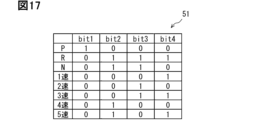
また、遷移禁止パターン52、および、遷移禁止パターン52の比較対象は、識別子に変換されたものであっても採用できる。例えば、図17の変形例2に示すように、制御パターン(更新値、前回値)および遷移禁止パターン52は、4ビットの識別子に変換したものを採用する。第1比較器40は、制御パターンの更新値が変換された識別子と、遷移禁止パターン52が変換された識別子とを比較する。
In addition, the
なお、変形例1と変形例2を組み合わせて実施することもできる。この場合、遷移パターンは、制御パターンの前回値が変換された識別子と、更新値が変換された識別子が並べられたものとなる。同様に、遷移禁止パターン52は、制御パターンの前回値が変換された識別子と、前回値が示す駆動状態からの駆動遷移が禁止されている駆動状態を示す通電パターンが変換された識別子が並べられたものとなる。
以上、本開示の好ましい実施形態について説明した。しかしながら、本開示は、上記実施形態に何ら制限されることはなく、本開示の趣旨を逸脱しない範囲において、種々の変形が可能である。以下に、本開示のその他の形態として、第2~第10実施形態に関して説明する。上記実施形態および第2~第10実施形態は、それぞれ単独で実施することも可能であるが、適宜組み合わせて実施することも可能である。本開示は、実施形態において示された組み合わせに限定されることなく、種々の組み合わせによって実施可能である。 Preferred embodiments of the present disclosure have been described above. However, the present disclosure is not limited to the above-described embodiments, and various modifications are possible without departing from the spirit of the present disclosure. Below, the second to tenth embodiments will be described as other aspects of the present disclosure. The above-described embodiments and the second to tenth embodiments can each be implemented alone, but can also be implemented in appropriate combinations. The present disclosure is not limited to the combinations shown in the embodiments, and can be implemented in various combinations.
(第2実施形態)
図18を用いて、第2実施形態の駆動装置100および負荷駆動システム1000に関して説明する。本実施形態では、主に、先行して説明した実施形態と異なる箇所に関して説明する。先行して説明した実施形態と同様に箇所に関しては、適宜採用することができる。この点は、下記の各実施形態でも同様である。
Second Embodiment
A
本実施形態の駆動装置100および負荷駆動システム1000は、第1実施形態と構成が同じである。よって、本実施形態では、第1実施形態と同じ符号を用いる。本実施形態は、遷移禁止パターン52のかわりに、遷移許可パターンを用いる点が第1実施形態と異なる。
The
ROM50は、通電パターン51と遷移許可パターンが記憶されている。ROM50は、通電パターン51が記憶された通電パターンメモリと、遷移許可パターンが記憶された遷移許可パターンメモリとを有しているともいえる。ROM50は、判定用記憶部にといえる。
The
遷移許可パターンは、各アクチュエータ40nへの駆動状態を示す通電パターンである。遷移許可パターンは、現駆動状態からの駆動遷移に相関する値である。遷移許可パターンは、制御パターンの更新値が異常であるか否かを判定するための判定値である。ROM50は、制御パターンと遷移許可パターンとが関連付けられて記憶されている。
The transition permission pattern is a current pattern that indicates the drive state of each
遷移許可パターンは、制御パターンの前回値が示す駆動状態からの駆動遷移が許可されている駆動状態を示すものである。遷移許可パターンは、現駆動状態からの駆動遷移許可を示すものといえる。遷移許可パターンは、自動変速機として許容される動作となる駆動遷移を示す通電パターンといえる。遷移許可パターンは、遷移判定値、許可判定値といえる。 The transition permission pattern indicates a drive state in which a drive transition from the drive state indicated by the previous value of the control pattern is permitted. The transition permission pattern can be said to indicate permission for a drive transition from the current drive state. The transition permission pattern can be said to be a current conduction pattern that indicates a drive transition that results in an operation permitted for an automatic transmission. The transition permission pattern can be said to be a transition determination value or a permission determination value.
駆動装置100は、負荷駆動信号を受信すると、図18のフローチャートに示す動作を開始する。なお、図18では、図15と同じ処理に同じステップ番号を付与している。
When the
ステップS50bでは、遷移許可パターンをセットする。シーケンス回路30は、遷移禁止パターン52をセットするのと同様に、遷移許可パターンを第4データレジスタ64にセットする。つまり、シーケンス回路30は、制御パターンの前回値に対応する遷移許可パターンをROM50から選択して、第4データレジスタ64にセットする。
In step S50b, the transition permission pattern is set. The
ステップS52bは、受信信号と遷移許可パターンを比較する。受信信号は、制御パターンの更新値といえる。第1比較器40は、第1データレジスタ61にセットされた制御パターンの更新値と、第4データレジスタ64にセットされた遷移許可パターンとを比較する(判定部)。ROM50に複数の遷移許可パターンが記憶されている場合は、上記実施形態と同様に比較する。
Step S52b compares the received signal with the transition permission pattern. The received signal can be considered as an updated value of the control pattern. The
第1比較器40は、制御パターンの更新値と少なくとも一つの遷移許可パターンとが一致した場合、ステップS53へ進む。この場合、制御パターンの更新値は、正常であるとみなせる。このように、第1比較器40は、制御パターンの更新値と少なくとも一つの遷移許可パターンとが一致する場合に、所定の対応関係を満たしていないと判定する。
If the update value of the control pattern matches at least one transition permission pattern, the
一方、第1比較器40は、制御パターンの更新値と全遷移許可パターンとが不一致の場合、ステップS54へ進む。この場合、制御パターンの更新値は、異常であるとみなせる。このように、第1比較器40は、制御パターンの更新値と全遷移許可パターンとが不一致の場合に、所定の対応関係を満たしていると判定する。また、遷移許可パターンと制御パターンの更新値とが不一致の状態は、制御パターンの更新値が遷移許可パターンに含まれないともいえる。
On the other hand, if the update value of the control pattern and all transition permission patterns do not match, the
第2実施形態の駆動装置100は、第1実施形態の駆動装置100と同様の効果を奏することができる。第2実施形態の負荷駆動システム1000は、第1実施形態の負荷駆動システム1000と同様の効果を奏することができる。
The
(第3実施形態)
図19を用いて、第3実施形態の駆動装置100および負荷駆動システム1000に関して説明する。例えば、本実施形態の駆動装置100および負荷駆動システム1000は、第1実施形態と構成が同じである。よって、本実施形態では、第1実施形態と同じ符号を用いる。
Third Embodiment
A driving
本実施形態は、現駆動状態として、制御パターンの前回値のかわりに、波形解析回路90で判定された車速を用いる点が第1実施形態と異なる。よって、本実施形態の駆動装置100は、波形解析回路90を備えている必要がある。
This embodiment differs from the first embodiment in that the vehicle speed determined by the
遷移禁止パターン52は、現駆動状態である波形解析回路90で判定された車速に関連づけられて記憶されている。遷移禁止パターン52は、例えば0と1などで示される各車速を示す信号に関連付けて記憶されている。例えば、高速に関連付けられた遷移禁止パターン52は、1速、Pレンジ、Rレンジを示す通電パターンを採用する。低速に関連付けられた遷移禁止パターン52は、Pレンジ、Rレンジを示す通電パターンを採用する。停車に関連付けられた遷移禁止パターン52は、3速、4速を示す通電パターンを採用する。遷移禁止パターン52は、遷移判定値、禁止判定値といえる。
The
駆動装置100は、負荷駆動信号を受信すると、図19のフローチャートに示す動作を開始する。ステップS65は、ステップS51と同様である。ステップS66aは、ステップS52aと同様である。ステップS67~ステップS69は、ステップS53~S55と同様である。
When the
ステップS60では、回転センサ信号を受信する。波形解析回路90は、回転センサ600から回転センサ信号を受信する。
In step S60, the rotation sensor signal is received. The
ステップS61では、車速を判定する。波形解析回路90は、受信した回転センサ信号から車速を判定する。波形解析回路90は、高速と判定した場合はステップS62へ進み、低速と判定した場合はステップS63へ進み、停車と判定した場合はステップS64へ進む。
In step S61, the vehicle speed is determined. The
ステップS62では、高速時の遷移禁止パターンをメモリからセットする。シーケンス回路30は、ROM50から高速に関連付けられた遷移禁止パターン52を第4データレジスタ64にセットする。
In step S62, the transition prohibition pattern for high speed is set from memory. The
ステップS63では、低速時の遷移禁止パターンをメモリからセットする。シーケンス回路30は、ROM50から低速に関連付けられた遷移禁止パターン52を第4データレジスタ64にセットする。
In step S63, the transition prohibition pattern for low speed is set from memory. The
ステップS64では、停車時の遷移禁止パターンをメモリからセットする。シーケンス回路30は、ROM50から停車に関連付けられた遷移禁止パターン52を第4データレジスタ64にセットする。
In step S64, the transition prohibition pattern when the vehicle is stopped is set from memory. The
このように、シーケンス回路30は、波形解析回路90で取得した車速に関連付けられた遷移禁止パターン52をROM50から取得する。なお、ステップS62~S64でのメモリは、ROM50における遷移禁止パターンメモリといえる。
In this way, the
第3実施形態の駆動装置100は、第1実施形態の駆動装置100と同様の効果を奏することができる。また、第3実施形態の負荷駆動システム1000は、第1実施形態の負荷駆動システム1000と同様の効果を奏することができる。
The
(第4実施形態)
図20を用いて、第4実施形態の駆動装置100および負荷駆動システム1000に関して説明する。本実施形態の駆動装置100および負荷駆動システム1000は、第1実施形態と構成が同じである。よって、本実施形態では、第1実施形態と同じ符号を用いる。本実施形態は、第3実施形態と同様、現駆動状態として、波形解析回路90で判定された車速を用いる。よって、本実施形態の駆動装置100は、波形解析回路90を備えている必要がある。また、本実施形態は、第2実施形態と同様、遷移判定値として遷移許可パターンを用いる。
Fourth Embodiment
The
遷移許可パターンは、現駆動状態である波形解析回路90で判定された車速に関連づけられて記憶されている。遷移許可パターンは、例えば0と1などで示される各車速を示す信号に関連付けて記憶されている。高速に関連付けられた遷移許可パターンは、2速、3速、4速を示す通電パターンを採用する。低速に関連付けられた遷移許可パターンは、1速、2速、3速を示す通電パターンを採用する。停車に関連付けられた遷移許可パターンは、1速、2速、Pレンジ、Rレンジを示す通電パターンを採用する。遷移許可パターンは、遷移判定値、許可判定値といえる。
The transition permission patterns are stored in association with the vehicle speed determined by the
駆動装置100は、負荷駆動信号を受信すると、図20のフローチャートに示す動作を開始する。図20では、図19と同じ処理に同じステップ番号を付与している。なお。ステップS66bは、ステップS52bと同様である。
When the
ステップS62aでは、高速時の遷移許可パターンをメモリからセットする。シーケンス回路30は、ROM50から高速に関連付けられた遷移許可パターンを第4データレジスタ64にセットする。
In step S62a, the transition permission pattern for high speed is set from memory. The
ステップS63aでは、低速時の遷移許可パターンをメモリからセットする。シーケンス回路30は、ROM50から低速に関連付けられた遷移許可パターンを第4データレジスタ64にセットする。
In step S63a, the transition permission pattern for low speed is set from memory. The
ステップS64aでは、停車時の遷移許可パターンをメモリからセットする。シーケンス回路30は、ROM50から停車に関連付けられた遷移許可パターンを第4データレジスタ64にセットする。
In step S64a, the transition permission pattern when the vehicle is stopped is set from memory. The
このように、シーケンス回路30は、波形解析回路90で取得した車速に関連付けられた遷移許可パターンをROM50から取得する。なお、ステップS62a~S64aでのメモリは、ROM50における遷移許可パターンメモリといえる。
In this way, the
第4実施形態の駆動装置100は、第1、第2、第3実施形態の駆動装置100と同様の効果を奏することができる。また、第4実施形態の負荷駆動システム1000は、第1、第2、第3実施形態の負荷駆動システム1000と同様の効果を奏することができる。
The
(第5実施形態)
図21を用いて、第5実施形態の駆動装置100および負荷駆動システム1000に関して説明する。本実施形態の駆動装置100および負荷駆動システム1000は、第1実施形態と構成が同じである。よって、本実施形態では、第1実施形態と同じ符号を用いる。本実施形態は、相関駆動状態として、制御パターンの更新値のかわりに、モニタレジスタ84に記憶されたモニタパターンを用いる点が第1実施形態と異なる。よって、本実施形態の駆動装置100は、電流検出抵抗81、増幅器82、第2比較器83、モニタレジスタ84を備えている必要がある。なお、本実施形態の遷移禁止パターン52は、第1実施形態のものと同様である。
Fifth Embodiment
The
駆動装置100は、負荷駆動信号を受信すると、図21のフローチャートに示す動作を開始する。なお、図21では、図15と同じ処理に同じステップ番号を付与している。
When the
ステップS52cでは、制御を開始する。CANコントローラ2は、制御パターンの更新値を制御レジスタ11に格納する。そして、駆動IC20は、制御レジスタ11に格納された制御パターンの更新値にしたがって、駆動スイッチ301~308を選択的にオンオフさせる。これによって、駆動IC20は、アクチュエータ40nを選択的に通電する。駆動IC20は、モニタパターンを取得するために、制御を行うとみなせる。
In step S52c, control is started. The
ステップS52dでは、制御結果をモニタする。駆動装置100は、上記のように電流検出抵抗81、増幅器82、第2比較器83が動作することで、モニタレジスタ84にモニタパターンを記憶させる。
In step S52d, the control result is monitored. The
ステップS52eでは、モニタ結果と遷移禁止パターンを比較する。モニタ結果は、モニタパターンといえる。第1比較器40は、第1データレジスタ61にセットされたモニタパターンと、第4データレジスタ64にセットされた遷移禁止パターン52とを比較する。ROM50に複数の遷移禁止パターン52が記憶されている場合は、上記実施形態と同様に比較する。
In step S52e, the monitor result is compared with the transition prohibition pattern. The monitor result can be said to be a monitor pattern. The
第1比較器40は、モニタパターンと全遷移禁止パターン52とが不一致の場合、ステップS53へ進む。この場合、モニタパターンは、正常であるとみなせる。また、モニタパターンが正常であることで、制御パターンの更新値が正常であるとみなせる。
If the monitor pattern does not match the full
一方、第1比較器40は、モニタパターンと遷移禁止パターン52とが一致した場合、ステップS54へ進む。つまり、第1比較器40は、遷移禁止パターン52の一つでもモニタパターンと一致した場合、ステップS54へ進む。この場合、モニタパターンは、異常であるとみなせる。このように、第1比較器40は、遷移禁止パターン52の一つでもモニタパターンと一致した場合に、所定の対応関係を満たしていると判定する。また、モニタパターンが異常であることで、制御パターンの更新値が異常であるとみなせる。
On the other hand, if the monitor pattern matches the
第5実施形態の駆動装置100は、第1実施形態の駆動装置100と同様の効果を奏することができる。また、第5実施形態の負荷駆動システム1000は、第1実施形態の負荷駆動システム1000と同様の効果を奏することができる。さらに、自動変速機は、例えば、実際に4速からPレンジへの遷移が指示された場合でも、油圧の応答等で、すぐにPレンジに遷移しない。このため、駆動装置100は、制御パターンの更新値のかわりにモニタパターンを用いることができる。
The
(第6実施形態)
図22を用いて、第6実施形態の駆動装置100および負荷駆動システム1000に関して説明する。本実施形態の駆動装置100および負荷駆動システム1000は、第1実施形態と構成が同じである。よって、本実施形態では、第1実施形態と同じ符号を用いる。本実施形態は、第5実施形態と同様、相関駆動状態として、制御パターンの更新値のかわりに、モニタレジスタ84に記憶されたモニタパターンを用いる。また、本実施形態は、第2実施形態と同様、遷移判定値として遷移許可パターンを用いる。
Sixth Embodiment
A
駆動装置100は、負荷駆動信号を受信すると、図22のフローチャートに示す動作を開始する。なお、図22では、図15、図18と同じ処理に同じステップ番号を付与している。また、ステップS52f、S52gは、ステップS52c、S52dと同様である。
When the
ステップS52hでは、モニタ結果と遷移許可パターンを比較する。モニタ結果は、モニタパターンといえる。第1比較器40は、第1データレジスタ61にセットされたモニタパターンと、第4データレジスタ64にセットされた遷移許可パターンとを比較する。ROM50に複数の遷移許可パターンが記憶されている場合は、上記実施形態と同様に比較する。
In step S52h, the monitor result is compared with the transition permission pattern. The monitor result can be said to be a monitor pattern. The
第1比較器40は、モニタパターンと少なくとも一つの遷移許可パターンとが一致した場合、ステップS53へ進む。この場合、モニタパターンは、正常であるとみなせる。このように、第1比較器40は、モニタパターンと少なくとも一つの遷移許可パターンとが一致する場合に、所定の対応関係を満たしていないと判定する。
If the monitor pattern matches at least one transition permission pattern, the
一方、第1比較器40は、モニタパターンと全遷移許可パターンとが不一致の場合、ステップS54へ進む。この場合、モニタパターンは、異常であるとみなせる。このように、第1比較器40は、モニタパターンと全遷移許可パターンとが不一致の場合に、所定の対応関係を満たしていると判定する。また、遷移許可パターンとモニタパターンとが不一致の状態は、モニタパターンが遷移許可パターンに含まれないともいえる。
On the other hand, if the monitor pattern and all transition permission patterns do not match, the
第6実施形態の駆動装置100は、第1、第2、第5実施形態の駆動装置100と同様の効果を奏することができる。第6実施形態の負荷駆動システム1000は、第1、第2、第5実施形態の負荷駆動システム1000と同様の効果を奏することができる。
The
(第7実施形態)
図23を用いて、第7実施形態の駆動装置100および負荷駆動システム1000に関して説明する。本実施形態の駆動装置100および負荷駆動システム1000は、第1実施形態と構成が同じである。よって、本実施形態では、第1実施形態と同じ符号を用いる。
Seventh Embodiment
A
本実施形態は、第3実施形態と同様、現駆動状態として波形解析回路90で判定された車速を用いる。よって、本実施形態の駆動装置100は、波形解析回路90を備えている必要がある。なお、本実施形態の遷移禁止パターン52は、第3実施形態のものと同様である。
In this embodiment, as in the third embodiment, the vehicle speed determined by the
また、本実施形態は、第5実施形態と同様、相関駆動状態としてモニタパターンを用いる。よって、本実施形態の駆動装置100は、電流検出抵抗81、増幅器82、第2比較器83、モニタレジスタ84を備えている必要がある。
In addition, like the fifth embodiment, this embodiment uses a monitor pattern as the correlated drive state. Therefore, the
駆動装置100は、負荷駆動信号を受信すると、図23のフローチャートに示す動作を開始する。なお、図23では、図20と同じ処理に同じステップ番号を付与している。また、ステップS66c~S66eは、ステップS52c~S52eと同様である。
When the
第7実施形態の駆動装置100は、第1、第3、第5実施形態の駆動装置100と同様の効果を奏することができる。また、第7実施形態の負荷駆動システム1000は、第1、第3、第5実施形態の負荷駆動システム1000と同様の効果を奏することができる。
The
(第8実施形態)
図24を用いて、第8実施形態の駆動装置100および負荷駆動システム1000に関して説明する。本実施形態の駆動装置100および負荷駆動システム1000は、第1実施形態と構成が同じである。よって、本実施形態では、第1実施形態と同じ符号を用いる。
Eighth embodiment
A
本実施形態は、第4実施形態と同様、現駆動状態として波形解析回路90で判定された車速を用いる。よって、本実施形態の駆動装置100は、波形解析回路90を備えている必要がある。なお、本実施形態の遷移許可パターンは、第4実施形態のものと同様である。
In this embodiment, as in the fourth embodiment, the vehicle speed determined by the
また、本実施形態は、第6実施形態と同様、相関駆動状態としてモニタパターンを用いる。よって、本実施形態の駆動装置100は、電流検出抵抗81、増幅器82、第2比較器83、モニタレジスタ84を備えている必要がある。
Furthermore, like the sixth embodiment, this embodiment uses a monitor pattern as the correlated drive state. Therefore, the
駆動装置100は、負荷駆動信号を受信すると、図24のフローチャートに示す動作を開始する。なお、図24では、図20と同じ処理に同じステップ番号を付与している。また、ステップS66f~S66hは、ステップS52f~S52hと同様である。
When the
第8実施形態の駆動装置100は、第1、第4、第6実施形態の駆動装置100と同様の効果を奏することができる。第8実施形態の負荷駆動システム1000は、第1、第4、第6実施形態の負荷駆動システム1000と同様の効果を奏することができる。
The
(第9実施形態)
図25、図26、図27を用いて、第9実施形態の駆動装置100および負荷駆動システム1000に関して説明する。本実施形態は、現駆動状態として、制御パターンの前回値のかわりに、センサ検出回路91の各検出結果を用いる点が第1実施形態と異なる。また、本実施形態の駆動装置100は、センサ検出回路91を備える点が第1実施形態の駆動装置100と異なる。センサ検出回路91は、センサ700が接続されている。
Ninth embodiment
A
図25に示すように、本実施形態のセンサ700は、油圧センサ701(OPS)と、回転センサ702(RS)と、油温センサ703(OTS)を有している。油圧センサ701は、油圧回路における作動油の圧力を示す信号を出力する。回転センサ702は、回転センサ600と同様である。油温センサ703は、油圧回路における作動油の温度を示す信号を出力する。センサ700は、負荷の駆動状態に応じた電気信号を出力するものである。
As shown in FIG. 25, the
センサ検出回路91(SEND)は、センサ700の信号を検出する。センサ検出回路91は、センサ700からの入力信号に対して所定処理、例えば波形検出、A/D変換などを行う。センサ検出回路91は、負荷の状態、すなわちバルブボディを含む自動変速機の状態を検出する。つまり、バルブボディを含む自動変速機の状態は、各アクチュエータ40nの現在の駆動状態である現駆動状態とみなせる。同様に、センサ検出回路91の各検出結果は、現駆動状態とみなせる。センサ検出回路91は、取得装置といえる。
The sensor detection circuit 91 (SEND) detects the signal of the
センサ検出回路91の各検出結果は、例えば0と1によって表すことができる。センサ検出回路91は、各検出結果をシーケンス回路30に出力する。また、センサ検出回路91は、各検出結果をモニタレジスタ84に書き込むようにしてもよい。
Each detection result of the
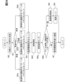
ROM50には、各検出結果と遷移禁止パターン52とが関連付けられて記憶されている。また、ROM50には、遷移禁止パターン52のかわりに、遷移許可パターンが各検出結果と関連付けられて記憶されていてもよい。ここでは、一例として、遷移禁止パターン52を採用する。
In the
駆動装置100は、所定時間ごとに、図26のフローチャートに示す動作を開始する。
The
ステップS70では、通信データを受信する。CANコントローラ2は、CANトランシーバ1を介して通信バスB1からフレームを受信する。CANコントローラ2は、受信したメッセージ等を抽出し、メッセージボックスに順次格納する。
In step S70, communication data is received. The
ステップS71では、データを取り出す。CANコントローラ2は、メッセージボックスから負荷駆動信号を示すデータを取り出す。CANコントローラ2は、取り出した負荷駆動信号を示すデータをレジスタに格納する。レジスタに格納した負荷駆動信号を示すデータは、制御パターンの更新値といえる。シーケンス回路30は、制御パターンの更新値を第1データレジスタ61にセットする。
In step S71, data is extracted. The
ステップS72では、状態を取得する。シーケンス回路30は、制御レジスタ11に記憶されている制御パターンの前回値を第2データレジスタ62にセットする。
In step S72, the state is acquired. The
ステップS73では、遷移を判定する。シーケンス回路30は、ステップS71で取り出した制御パターンの更新値と、ステップS72で取得した制御パターンの前回値とから駆動遷移を判定する。つまり、シーケンス回路30は、現駆動状態から、制御パターンの更新値が示す駆動状態への駆動遷移を判定する。
In step S73, the transition is determined. The
シーケンス回路30は、例えば、図16に示すように、制御パターンの更新値と制御パターンの前回値とを組み合わせた遷移パターンを生成することで、駆動遷移を判定する。この場合、シーケンス回路30は、図16に示すように、遷移パターンに対応する遷移禁止パターン52を第4データレジスタ64にセットする。
The
ステップS74では、比較する。第1比較器40は、遷移パターンと遷移禁止パターン52とを比較する。第1比較器40は、遷移パターンと全遷移禁止パターン52とが不一致の場合、ステップS75へ進む。この場合、制御パターンの更新値は、正常であるとみなせる。
In step S74, a comparison is made. The
一方、第1比較器40は、遷移パターンと遷移禁止パターン52とが一致した場合、ステップS77へ進む。つまり、第1比較器40は、遷移禁止パターン52の一つでも制御パターンの更新値と一致した場合、ステップS77へ進む。この場合、制御パターンの更新値は、異常であるとみなせる。
On the other hand, if the transition pattern matches the
ステップS75では、正常通信と判定する。第1比較器40は、正常通信と判定する。このとき、第1比較器40は、第2信号線L2を介して、ECU200に正常信号を出力してもよい。
In step S75, it is determined that the communication is normal. The
ステップS76では、駆動IC20を制御する。ステップS76は、ステップS53と同様である。
In step S76, the driving
ステップS77では、データを破棄する。第1比較器40は、上記のように、制御パターンの更新値が異常であることを示す異常信号をCANコントローラ2に出力する。CANコントローラ2は、異常信号が入力されると、制御パターンの更新値をSPI回路10に出力することなく破棄する。CANコントローラ2は、制御パターンの更新値をSPI回路10に出力しないことで制御パターンの更新値を破棄する。なお、CANコントローラ2は、異常信号が入力された時点で記憶している制御パターンの更新値を消去することで破棄してもよい。
In step S77, the data is discarded. As described above, the
このように、第1比較器40は、異常信号をCANコントローラ2に出力することで、異常と判定した制御パターンの更新値を制御レジスタ11に記憶させない。このため、駆動装置100は、異常と判定された制御パターンの更新値が制御レジスタ11に書き込まれない。よって、駆動装置100は、異常と判定された制御パターンの更新値によって、各アクチュエータ40nの駆動を制御することを抑制できる。
In this way, the
ステップS78では、データ破棄を通知する。第1比較器40は、第2信号線L2を介して、ECU200に異常信号を出力する。異常信号は、制御パターンの更新値が異常であることなどを示すとともに、データの破棄を通知する信号である。ここでのデータは、制御パターンの更新値である。また、このように、駆動装置100は、マイコンなどを用いることなく、第1比較器40が異常信号を出力する。
In step S78, the data is notified to be discarded. The
なお、第1比較器40は、異常信号を給電回路70に出力しなくてもよい。また、ステップS77、S78は、他の実施形態にも適用できる。
The
ECU200の動作に関して説明する。ECU200は、所定時間ごとに、図27のフローチャートに示す動作を開始する。なお、ステップS80,S81は、ステップS10,S11と同様である。
The operation of the
ステップS82では、データの破棄通知の有無を判定する。CPU2011は、第2信号線L2を介して、駆動装置100からデータの破棄通知を受信したか否かによって、破棄通知の有無を判定する。CPU2011は、破棄通知を受信した場合に破棄通知有りと判定してステップS84へ進み、破棄通知を受信してない場合に破棄通知無しと判定してステップS83へ進む。
In step S82, it is determined whether or not a data discard notification has been received. The
ステップS83では、正常判定する。CPU2011は、駆動装置100との通信が正常であると判定する。
In step S83, a normal determination is made. The
ステップS84では、通知をカウントする。CPU2011は、破棄通知をカウントする。ステップS85~S87は、ステップS18~S20と同様である。
In step S84, the notifications are counted. The
第9実施形態の駆動装置100は、第1実施形態の駆動装置100と同様の効果を奏することができる。また、第9実施形態の負荷駆動システム1000は、第1実施形態の負荷駆動システム1000と同様の効果を奏することができる。さらに、第9実施形態の負荷駆動システム1000は、通信異常が発生した場合に、ECU200から、各アクチュエータ40nの電源状態を遮断状態とすることができる。このため、第9実施形態の負荷駆動システム1000は、駆動装置100をより一層簡易な構成とすることができる。
The
(第10実施形態)
図28を用いて、第10実施形態の駆動装置100および負荷駆動システム1000に関して説明する。本実施形態では、便宜的に、第1実施形態と同じ符号を用いている。
Tenth embodiment
A driving
第10実施形態の駆動装置100は、シフトバイワイヤシステムにおけるモータ800を駆動制御する点が上記実施形態と異なる。よって、アクチュエータ401~403は、モータ800のU相巻き線、V相巻き線、W相巻き線といえる。
The
本実施形態の駆動装置100は、センサ検出回路92を備える点が第1実施形態の駆動装置100と異なる。本実施形態は、現駆動状態として、制御パターンの前回値のかわりに、センサ検出回路92の各検出結果を用いる点が第1実施形態と異なる。本実施形態は、遷移判定値が、現駆動状態と車両状態からの駆動遷移に相関する値である点が第1実施形態と異なる。
The
本実施形態は、負荷駆動信号における各アクチュエータ401~403への駆動状態を指示する信号が制御レジスタ11の各アドレスのビットに書き込まれる点が第1実施形態と異なる。本実施形態では、制御レジスタ11に記憶された制御パターンの更新値に相関する各アクチュエータ401~408の相関駆動状態として、制御パターンの更新値そのものを採用している。
This embodiment differs from the first embodiment in that the signal instructing the drive state of each actuator 401-403 in the load drive signal is written to a bit of each address in the
シフトバイワイヤシステムは、モータ800のほかにも、パーキングロック(Pロック)機構やシフトレンジ切替機構などを備えている。モータ800は、図示しない車両に搭載されるバッテリから電力が供給されることで回転し、シフトレンジ切替機構の駆動源として機能する。モータ800は、給電スイッチ500のオンにより、各アクチュエータ40nに対して電流の供給が可能となる。給電スイッチ500のオフにより、各アクチュエータ40nに対する電流の供給が遮断される。
In addition to the
制御パターンの更新値は、例えば、Pロックの解除などを示すものを採用できる。つまり、ECU200は、駆動装置100に対する負荷駆動信号として、単にモータ800の回転を指示する信号だけではなく、Pロックの解除を指示する信号なども含まれる。
The update value of the control pattern can be, for example, one that indicates the release of the P lock. In other words, the
本実施形態のセンサは、ブレーキスイッチ704、Pロックセンサ705を有している。ブレーキスイッチ704(BS)は、ブレーキペダルが踏み込まれた状態か、ブレーキペダルが踏み込まれていない状態かを示す信号を出力する。また、ブレーキスイッチ704は、ブレーキペダルの踏み込み量に応じた信号を出力するものであってもよい。Pロックセンサ705(PLS)は、Pロックがロック状態か非ロック状態かを示す信号を出力する。
The sensor in this embodiment has a
センサ検出回路92(SEND)は、センサ700の信号を検出する。センサ検出回路92は、センサ700からの入力信号に対して所定処理、例えば波形検出、A/D変換などを行う。センサ検出回路92は、負荷の状態、すなわちシフトバイワイヤシステムの状態を検出する。つまり、シフトバイワイヤシステムの状態は、各アクチュエータ40nの現在の駆動状態である現駆動状態とみなせる。同様に、センサ検出回路92の検出結果は、現駆動状態とみなせる。また、センサ検出回路92は、車両のブレーキペダルの踏み込み状態を検出する。車両のブレーキペダルの踏み込み状態は、車両状態とみなせる。センサ検出回路92は、取得部といえる。
The sensor detection circuit 92 (SEND) detects the signal of the
センサ検出回路92の各検出結果は、例えば0と1によって表すことができる。センサ検出回路92は、各検出結果をシーケンス回路30に出力する。また、センサ検出回路92は、各検出結果をモニタレジスタ84に書き込むようにしてもよい。
Each detection result of the
ROM50には、センサ検出回路92の各検出結果と遷移禁止パターン52とが関連付けられて記憶されている。つまり、遷移禁止パターン52は、現駆動状態と車両状態に関連付けられている。また、ROM50には、遷移禁止パターン52のかわりに、遷移許可パターンが各検出結果と関連付けられて記憶されていてもよい。ここでは、一例として、遷移禁止パターン52を採用する。
In the
シーケンス回路30は、各検出結果に基づいて、現駆動状態と車両状態を判定する。また、シーケンス回路30は、各検出結果に関連付けられた遷移禁止パターン52を第4データレジスタ64にセットする。遷移禁止パターン52は、例えば、Pロックがロック状態で、ブレーキペダルが踏み込まれていない状態に対して、Pロックの解除を示す制御パターンの更新値などを採用できる。
The
第1比較器40は、上記実施形態と同様に、制御パターンの更新値と、遷移禁止パターン52とを比較する。第1比較器40は、制御パターンの更新値と遷移禁止パターン52とが一致した場合に異常と判定し、不一致の場合に正常と判定する。
As in the above embodiment, the
第10実施形態の駆動装置100は、第1実施形態の駆動装置100と同様の効果を奏することができる。第10実施形態の負荷駆動システム1000は、第1実施形態の負荷駆動システム1000と同様の効果を奏することができる。
The
1…CANトランシーバ、2…CANコントローラ、10…SPI回路、11…制御レジスタ、20…駆動IC、30…シーケンス回路、40…第1比較器、50…ROM、51…通電パターン、52…遷移禁止パターン、60…レジスタ部、61…第1データレジスタ、62…第2データレジスタ、63…第3データレジスタ、64…第4データレジスタ、70…給電回路、81…電流検出抵抗、82…増幅器、83…第2比較器、84…モニタレジスタ、90…波形解析回路、91,92…センサ検出回路、100…駆動装置、200…ECU、301~30n…第1~第n駆動スイッチ、401~40n…第1~第nアクチュエータ、500…給電スイッチ、600…回転センサ、700…センサ、701…油圧センサ、702…回転センサ、703…油温センサ、704…ブレーキスイッチ、705…Pロックセンサ、1000…負荷駆動システム、L1…第1信号線、L2…第2信号線、L3…第3信号線 1...CAN transceiver, 2...CAN controller, 10...SPI circuit, 11...control register, 20...driver IC, 30...sequence circuit, 40...first comparator, 50...ROM, 51...energization pattern, 52...transition prohibition pattern, 60...register section, 61...first data register, 62...second data register, 63...third data register, 64...fourth data register, 70...power supply circuit, 81...current detection resistor, 82...amplifier, 83...second comparator, 84...monitor register, 90...waveform analysis circuit, 91, 92...sensor detection circuit, 100...drive device, 200...ECU, 301-30n...first to nth drive switches, 401-40n...first to nth actuators, 500...power supply switch, 600...rotation sensor, 700...sensor, 701...oil pressure sensor, 702...rotation sensor, 703...oil temperature sensor, 704...brake switch, 705...P lock sensor, 1000...load drive system, L1...first signal line, L2...second signal line, L3...third signal line
Claims (9)
前記負荷制御装置は、前記負荷の駆動状態を指示する駆動情報を含む複数のメッセージを、前記通信バスを介して前記負荷駆動装置に送信する送信部(S12)を備え、
前記負荷駆動装置は、
前記通信バスを介して前記メッセージを受信し、受信した前記メッセージを受信用のメッセージボックスに格納し、前記メッセージボックスから前記駆動情報を含む駆動指示メッセージを抜き出し、前記駆動指示メッセージを負荷駆動信号に変換するものであり、
前記負荷駆動信号に基づいて前記負荷を駆動する駆動部(S35)と、
前記信号線を介して前記負荷制御装置に前記負荷駆動信号を通知する通知部(S34)と、を備え、
前記負荷制御装置は、
前記信号線を介して前記負荷駆動信号を取得する取得部(S13)と、
前記送信部から送信した前記駆動指示メッセージと、前記取得部で取得した前記負荷駆動信号とを比較する比較部(S14)と、
前記送信部から送信した前記駆動指示メッセージと、前記取得部で取得した前記負荷駆動信号とが所定の対応関係を満たさない場合に前記取得部で前記負荷駆動信号を取得した回数をカウントし、前記カウントしたカウント数が所定回数を超えると、前記取得部で取得した前記負荷駆動信号が異常であり、前記負荷駆動装置が前記負荷を異常に駆動する状態であると判定する異常判定部(S17~S19)と、を備えている負荷駆動システム。 A load driving system for driving a load, comprising: a load control device (200), a load driving device (100), a communication bus (B1) connecting the load control device and the load driving device, and a signal line (L3) different from the communication bus connecting the load control device and the load driving device,
The load control device includes a transmission unit (S12) that transmits a plurality of messages including driving information instructing a driving state of the load to the load driving device via the communication bus;
The load driver includes:
receiving the message via the communication bus, storing the received message in a message box for reception, extracting a drive instruction message including the drive information from the message box, and converting the drive instruction message into a load drive signal;
A drive unit (S35) that drives the load based on the load drive signal;
a notification unit (S34) that notifies the load control device of the load drive signal via the signal line ,
The load control device includes:
an acquisition unit (S13) that acquires the load drive signal via the signal line;
a comparison unit (S14) that compares the drive instruction message transmitted from the transmission unit with the load drive signal acquired by the acquisition unit;
The load driving system includes an abnormality determination unit (S17 to S19) that counts the number of times the load driving signal is acquired by the acquisition unit when the drive instruction message transmitted from the transmission unit and the load driving signal acquired by the acquisition unit do not satisfy a predetermined correspondence relationship, and determines that the load driving signal acquired by the acquisition unit is abnormal and that the load driving device is in a state where it is abnormally driving the load when the counted number exceeds a predetermined number .
前記負荷駆動装置は、前記通信バスを介して前記フレームを受信し、前記フレームから前記駆動指示メッセージを抜き出す請求項1~8のいずれか1項に記載の負荷駆動システム。 The load controller transmits a frame including the message via the communication bus;
9. The load driving system according to claim 1 , wherein the load driving device receives the frame via the communication bus and extracts the drive instruction message from the frame.
Priority Applications (4)
| Application Number | Priority Date | Filing Date | Title |
|---|---|---|---|
| JP2021002301A JP7646366B2 (en) | 2021-01-08 | 2021-01-08 | Load Drive System |
| US17/558,695 US11719333B2 (en) | 2021-01-08 | 2021-12-22 | Load drive system |
| DE102022100179.2A DE102022100179A1 (en) | 2021-01-08 | 2022-01-05 | LOAD CONTROL SYSTEM |
| CN202210015182.4A CN114750712A (en) | 2021-01-08 | 2022-01-07 | load drive system |
Applications Claiming Priority (1)
| Application Number | Priority Date | Filing Date | Title |
|---|---|---|---|
| JP2021002301A JP7646366B2 (en) | 2021-01-08 | 2021-01-08 | Load Drive System |
Publications (2)
| Publication Number | Publication Date |
|---|---|
| JP2022107380A JP2022107380A (en) | 2022-07-21 |
| JP7646366B2 true JP7646366B2 (en) | 2025-03-17 |
Family
ID=82116438
Family Applications (1)
| Application Number | Title | Priority Date | Filing Date |
|---|---|---|---|
| JP2021002301A Active JP7646366B2 (en) | 2021-01-08 | 2021-01-08 | Load Drive System |
Country Status (4)
| Country | Link |
|---|---|
| US (1) | US11719333B2 (en) |
| JP (1) | JP7646366B2 (en) |
| CN (1) | CN114750712A (en) |
| DE (1) | DE102022100179A1 (en) |
Families Citing this family (1)
| Publication number | Priority date | Publication date | Assignee | Title |
|---|---|---|---|---|
| JP2024018637A (en) * | 2022-07-29 | 2024-02-08 | マツダ株式会社 | vehicle control system |
Citations (4)
| Publication number | Priority date | Publication date | Assignee | Title |
|---|---|---|---|---|
| JP2000312151A (en) | 1999-04-27 | 2000-11-07 | Denso Corp | Electronic controller |
| JP2001230760A (en) | 2000-02-17 | 2001-08-24 | Mitsubishi Electric Corp | Semiconductor integrated circuit device and data transmission method |
| JP2005217863A (en) | 2004-01-30 | 2005-08-11 | Tamura Seisakusho Co Ltd | Ip telephone terminal, control method and program thereof, and ip telephone system |
| JP2008263678A (en) | 2007-04-10 | 2008-10-30 | Yaskawa Electric Corp | Servo motor control device |
Family Cites Families (20)
| Publication number | Priority date | Publication date | Assignee | Title |
|---|---|---|---|---|
| GB8803044D0 (en) * | 1988-02-10 | 1988-03-09 | Salplex Ltd | Information handling & control systems |
| US5305215A (en) * | 1991-05-15 | 1994-04-19 | Phoenix International Corporation | Expandable, mobile, modular microcomputer system for an off-road vehicle |
| US20040113412A1 (en) * | 1997-11-11 | 2004-06-17 | Go Giok Djien | Multi-point seat belt |
| JP3882786B2 (en) * | 2003-05-30 | 2007-02-21 | セイコーエプソン株式会社 | Device fault handling request system, fault handling request server, device fault handling request program, and device fault handling request method |
| JP4379793B2 (en) | 2004-03-12 | 2009-12-09 | 株式会社デンソー | Electronic control device for vehicle |
| GB0605499D0 (en) * | 2006-03-17 | 2006-04-26 | Britax Roemer Kindersicherheit Gmbh | Belt guide |
| DE102009000251A1 (en) * | 2009-01-15 | 2010-07-22 | Zf Friedrichshafen Ag | Electronic drive control device for controlling operation of motor vehicle drive coupled with drive assembly, has modular functional architecture with multiple consecutively connected control modules |
| JP4889762B2 (en) * | 2009-05-21 | 2012-03-07 | 三菱電機株式会社 | Vehicle control device |
| JP3164645U (en) * | 2010-09-28 | 2010-12-09 | 利昭 丹治 | Seat belt |
| JP5333501B2 (en) * | 2011-03-31 | 2013-11-06 | 株式会社デンソー | Vehicle behavior data storage control system and storage device |
| JP5541245B2 (en) | 2011-07-19 | 2014-07-09 | 株式会社デンソー | Fuel injection control device |
| JP5741480B2 (en) | 2012-02-17 | 2015-07-01 | 株式会社オートネットワーク技術研究所 | Communication system, relay device, and power supply control method |
| EP2892199B1 (en) | 2014-01-06 | 2018-08-22 | Argus Cyber Security Ltd. | Global automotive safety system |
| US9998040B2 (en) | 2015-06-05 | 2018-06-12 | Denso Corporation | Motor driver of motor for valve timing control of internal combustion engine |
| JP6471739B2 (en) * | 2016-11-18 | 2019-02-20 | トヨタ自動車株式会社 | In-vehicle communication system |
| JP2018103972A (en) * | 2016-12-22 | 2018-07-05 | パナソニックIpマネジメント株式会社 | On-vehicle control device |
| JP2018121109A (en) | 2017-01-23 | 2018-08-02 | 本田技研工業株式会社 | COMMUNICATION SYSTEM, MOBILE BODY, AND COMMUNICATION METHOD |
| JP2019219718A (en) * | 2018-06-15 | 2019-12-26 | セイコーエプソン株式会社 | Circuit device, electronic apparatus and moving body |
| JP2019218773A (en) | 2018-06-21 | 2019-12-26 | 株式会社ケーヒン | Control system for vehicle electrically-driven component |
| JP2020108132A (en) | 2018-12-26 | 2020-07-09 | パナソニックIpマネジメント株式会社 | Electronic control system, electronic control device, control method, and program |
-
2021
- 2021-01-08 JP JP2021002301A patent/JP7646366B2/en active Active
- 2021-12-22 US US17/558,695 patent/US11719333B2/en active Active
-
2022
- 2022-01-05 DE DE102022100179.2A patent/DE102022100179A1/en active Pending
- 2022-01-07 CN CN202210015182.4A patent/CN114750712A/en active Pending
Patent Citations (4)
| Publication number | Priority date | Publication date | Assignee | Title |
|---|---|---|---|---|
| JP2000312151A (en) | 1999-04-27 | 2000-11-07 | Denso Corp | Electronic controller |
| JP2001230760A (en) | 2000-02-17 | 2001-08-24 | Mitsubishi Electric Corp | Semiconductor integrated circuit device and data transmission method |
| JP2005217863A (en) | 2004-01-30 | 2005-08-11 | Tamura Seisakusho Co Ltd | Ip telephone terminal, control method and program thereof, and ip telephone system |
| JP2008263678A (en) | 2007-04-10 | 2008-10-30 | Yaskawa Electric Corp | Servo motor control device |
Also Published As
| Publication number | Publication date |
|---|---|
| CN114750712A (en) | 2022-07-15 |
| US20220221049A1 (en) | 2022-07-14 |
| US11719333B2 (en) | 2023-08-08 |
| DE102022100179A1 (en) | 2022-07-14 |
| JP2022107380A (en) | 2022-07-21 |
Similar Documents
| Publication | Publication Date | Title |
|---|---|---|
| US8712635B2 (en) | In-vehicle electronic control apparatus having monitoring control circuit | |
| JP3857678B2 (en) | Vehicle transmission system | |
| CN101910669B (en) | Clutch actuator and method for controlling the clutch actuator | |
| US9008808B2 (en) | Control system for safely operating at least one functional component | |
| US20070112483A1 (en) | System for failure safety control between controllers of hybrid vehicle | |
| KR101673780B1 (en) | Control method of breakdown diagnosis | |
| JP7646366B2 (en) | Load Drive System | |
| JP7443994B2 (en) | Drives and drive systems | |
| JP2004066974A (en) | Vehicle control device and its communication method | |
| CN112867653B (en) | Method and system for controlling transmission gear in response to engine communication loss | |
| JP2006117131A (en) | Electronic control device for vehicle | |
| US11993215B2 (en) | Drive device | |
| JP5939236B2 (en) | Motor control device | |
| KR101006680B1 (en) | Monitoring device of automatic transmission unit | |
| JP6895356B2 (en) | Electronic control device for vehicles | |
| JP5361873B2 (en) | Method and system for feeding back the state of an electrical component to an engine controller of an internal combustion engine | |
| US12325368B2 (en) | Drive circuit for controlling conduction states of multiple loads | |
| JPWO2018193533A1 (en) | Electronic control device and control method for realizing secure parking lock | |
| JP7070441B2 (en) | Shift-by-wire controller | |
| JP6647188B2 (en) | Transmission control device | |
| JP2016098923A (en) | Shift control device for continuously variable transmission | |
| KR100200124B1 (en) | Fail-safe control device and method | |
| JP2018079737A (en) | Electronic controller and diagnosis method for the same |
Legal Events
| Date | Code | Title | Description |
|---|---|---|---|
| A621 | Written request for application examination |
Free format text: JAPANESE INTERMEDIATE CODE: A621 Effective date: 20230410 |
|
| A977 | Report on retrieval |
Free format text: JAPANESE INTERMEDIATE CODE: A971007 Effective date: 20240227 |
|
| A131 | Notification of reasons for refusal |
Free format text: JAPANESE INTERMEDIATE CODE: A131 Effective date: 20240312 |
|
| A521 | Request for written amendment filed |
Free format text: JAPANESE INTERMEDIATE CODE: A523 Effective date: 20240508 |
|
| A02 | Decision of refusal |
Free format text: JAPANESE INTERMEDIATE CODE: A02 Effective date: 20240702 |
|
| A521 | Request for written amendment filed |
Free format text: JAPANESE INTERMEDIATE CODE: A523 Effective date: 20240926 |
|
| A911 | Transfer to examiner for re-examination before appeal (zenchi) |
Free format text: JAPANESE INTERMEDIATE CODE: A911 Effective date: 20241004 |
|
| A912 | Re-examination (zenchi) completed and case transferred to appeal board |
Free format text: JAPANESE INTERMEDIATE CODE: A912 Effective date: 20241025 |
|
| A61 | First payment of annual fees (during grant procedure) |
Free format text: JAPANESE INTERMEDIATE CODE: A61 Effective date: 20250305 |
|
| R150 | Certificate of patent or registration of utility model |
Ref document number: 7646366 Country of ref document: JP Free format text: JAPANESE INTERMEDIATE CODE: R150 |