JP7645552B2 - scope - Google Patents
scope Download PDFInfo
- Publication number
- JP7645552B2 JP7645552B2 JP2022504200A JP2022504200A JP7645552B2 JP 7645552 B2 JP7645552 B2 JP 7645552B2 JP 2022504200 A JP2022504200 A JP 2022504200A JP 2022504200 A JP2022504200 A JP 2022504200A JP 7645552 B2 JP7645552 B2 JP 7645552B2
- Authority
- JP
- Japan
- Prior art keywords
- camera
- probe
- housing
- scope
- cleaning
- Prior art date
- Legal status (The legal status is an assumption and is not a legal conclusion. Google has not performed a legal analysis and makes no representation as to the accuracy of the status listed.)
- Active
Links
Images


Classifications
-
- A—HUMAN NECESSITIES
- A61—MEDICAL OR VETERINARY SCIENCE; HYGIENE
- A61B—DIAGNOSIS; SURGERY; IDENTIFICATION
- A61B1/00—Instruments for performing medical examinations of the interior of cavities or tubes of the body by visual or photographical inspection, e.g. endoscopes; Illuminating arrangements therefor
- A61B1/00002—Operational features of endoscopes
- A61B1/00011—Operational features of endoscopes characterised by signal transmission
- A61B1/00016—Operational features of endoscopes characterised by signal transmission using wireless means
-
- A—HUMAN NECESSITIES
- A61—MEDICAL OR VETERINARY SCIENCE; HYGIENE
- A61B—DIAGNOSIS; SURGERY; IDENTIFICATION
- A61B1/00—Instruments for performing medical examinations of the interior of cavities or tubes of the body by visual or photographical inspection, e.g. endoscopes; Illuminating arrangements therefor
- A61B1/00002—Operational features of endoscopes
- A61B1/00011—Operational features of endoscopes characterised by signal transmission
- A61B1/00018—Operational features of endoscopes characterised by signal transmission using electrical cables
-
- A—HUMAN NECESSITIES
- A61—MEDICAL OR VETERINARY SCIENCE; HYGIENE
- A61B—DIAGNOSIS; SURGERY; IDENTIFICATION
- A61B1/00—Instruments for performing medical examinations of the interior of cavities or tubes of the body by visual or photographical inspection, e.g. endoscopes; Illuminating arrangements therefor
- A61B1/00002—Operational features of endoscopes
- A61B1/00025—Operational features of endoscopes characterised by power management
- A61B1/00027—Operational features of endoscopes characterised by power management characterised by power supply
- A61B1/00029—Operational features of endoscopes characterised by power management characterised by power supply externally powered, e.g. wireless
-
- A—HUMAN NECESSITIES
- A61—MEDICAL OR VETERINARY SCIENCE; HYGIENE
- A61B—DIAGNOSIS; SURGERY; IDENTIFICATION
- A61B1/00—Instruments for performing medical examinations of the interior of cavities or tubes of the body by visual or photographical inspection, e.g. endoscopes; Illuminating arrangements therefor
- A61B1/00064—Constructional details of the endoscope body
- A61B1/00071—Insertion part of the endoscope body
- A61B1/0008—Insertion part of the endoscope body characterised by distal tip features
- A61B1/00096—Optical elements
-
- A—HUMAN NECESSITIES
- A61—MEDICAL OR VETERINARY SCIENCE; HYGIENE
- A61B—DIAGNOSIS; SURGERY; IDENTIFICATION
- A61B1/00—Instruments for performing medical examinations of the interior of cavities or tubes of the body by visual or photographical inspection, e.g. endoscopes; Illuminating arrangements therefor
- A61B1/00112—Connection or coupling means
- A61B1/00114—Electrical cables in or with an endoscope
-
- A—HUMAN NECESSITIES
- A61—MEDICAL OR VETERINARY SCIENCE; HYGIENE
- A61B—DIAGNOSIS; SURGERY; IDENTIFICATION
- A61B1/00—Instruments for performing medical examinations of the interior of cavities or tubes of the body by visual or photographical inspection, e.g. endoscopes; Illuminating arrangements therefor
- A61B1/00163—Optical arrangements
- A61B1/00172—Optical arrangements with means for scanning
-
- A—HUMAN NECESSITIES
- A61—MEDICAL OR VETERINARY SCIENCE; HYGIENE
- A61B—DIAGNOSIS; SURGERY; IDENTIFICATION
- A61B1/00—Instruments for performing medical examinations of the interior of cavities or tubes of the body by visual or photographical inspection, e.g. endoscopes; Illuminating arrangements therefor
- A61B1/00163—Optical arrangements
- A61B1/00174—Optical arrangements characterised by the viewing angles
- A61B1/00183—Optical arrangements characterised by the viewing angles for variable viewing angles
-
- A—HUMAN NECESSITIES
- A61—MEDICAL OR VETERINARY SCIENCE; HYGIENE
- A61B—DIAGNOSIS; SURGERY; IDENTIFICATION
- A61B1/00—Instruments for performing medical examinations of the interior of cavities or tubes of the body by visual or photographical inspection, e.g. endoscopes; Illuminating arrangements therefor
- A61B1/00163—Optical arrangements
- A61B1/00188—Optical arrangements with focusing or zooming features
-
- A—HUMAN NECESSITIES
- A61—MEDICAL OR VETERINARY SCIENCE; HYGIENE
- A61B—DIAGNOSIS; SURGERY; IDENTIFICATION
- A61B1/00—Instruments for performing medical examinations of the interior of cavities or tubes of the body by visual or photographical inspection, e.g. endoscopes; Illuminating arrangements therefor
- A61B1/00163—Optical arrangements
- A61B1/00193—Optical arrangements adapted for stereoscopic vision
-
- A—HUMAN NECESSITIES
- A61—MEDICAL OR VETERINARY SCIENCE; HYGIENE
- A61B—DIAGNOSIS; SURGERY; IDENTIFICATION
- A61B1/00—Instruments for performing medical examinations of the interior of cavities or tubes of the body by visual or photographical inspection, e.g. endoscopes; Illuminating arrangements therefor
- A61B1/012—Instruments for performing medical examinations of the interior of cavities or tubes of the body by visual or photographical inspection, e.g. endoscopes; Illuminating arrangements therefor characterised by internal passages or accessories therefor
- A61B1/015—Control of fluid supply or evacuation
-
- A—HUMAN NECESSITIES
- A61—MEDICAL OR VETERINARY SCIENCE; HYGIENE
- A61B—DIAGNOSIS; SURGERY; IDENTIFICATION
- A61B1/00—Instruments for performing medical examinations of the interior of cavities or tubes of the body by visual or photographical inspection, e.g. endoscopes; Illuminating arrangements therefor
- A61B1/012—Instruments for performing medical examinations of the interior of cavities or tubes of the body by visual or photographical inspection, e.g. endoscopes; Illuminating arrangements therefor characterised by internal passages or accessories therefor
- A61B1/018—Instruments for performing medical examinations of the interior of cavities or tubes of the body by visual or photographical inspection, e.g. endoscopes; Illuminating arrangements therefor characterised by internal passages or accessories therefor for receiving instruments
-
- A—HUMAN NECESSITIES
- A61—MEDICAL OR VETERINARY SCIENCE; HYGIENE
- A61B—DIAGNOSIS; SURGERY; IDENTIFICATION
- A61B1/00—Instruments for performing medical examinations of the interior of cavities or tubes of the body by visual or photographical inspection, e.g. endoscopes; Illuminating arrangements therefor
- A61B1/04—Instruments for performing medical examinations of the interior of cavities or tubes of the body by visual or photographical inspection, e.g. endoscopes; Illuminating arrangements therefor combined with photographic or television appliances
- A61B1/05—Instruments for performing medical examinations of the interior of cavities or tubes of the body by visual or photographical inspection, e.g. endoscopes; Illuminating arrangements therefor combined with photographic or television appliances characterised by the image sensor, e.g. camera, being in the distal end portion
- A61B1/051—Details of CCD assembly
-
- A—HUMAN NECESSITIES
- A61—MEDICAL OR VETERINARY SCIENCE; HYGIENE
- A61B—DIAGNOSIS; SURGERY; IDENTIFICATION
- A61B1/00—Instruments for performing medical examinations of the interior of cavities or tubes of the body by visual or photographical inspection, e.g. endoscopes; Illuminating arrangements therefor
- A61B1/06—Instruments for performing medical examinations of the interior of cavities or tubes of the body by visual or photographical inspection, e.g. endoscopes; Illuminating arrangements therefor with illuminating arrangements
- A61B1/0627—Instruments for performing medical examinations of the interior of cavities or tubes of the body by visual or photographical inspection, e.g. endoscopes; Illuminating arrangements therefor with illuminating arrangements for variable illumination angles
-
- A—HUMAN NECESSITIES
- A61—MEDICAL OR VETERINARY SCIENCE; HYGIENE
- A61B—DIAGNOSIS; SURGERY; IDENTIFICATION
- A61B1/00—Instruments for performing medical examinations of the interior of cavities or tubes of the body by visual or photographical inspection, e.g. endoscopes; Illuminating arrangements therefor
- A61B1/06—Instruments for performing medical examinations of the interior of cavities or tubes of the body by visual or photographical inspection, e.g. endoscopes; Illuminating arrangements therefor with illuminating arrangements
- A61B1/0661—Endoscope light sources
- A61B1/0676—Endoscope light sources at distal tip of an endoscope
-
- A—HUMAN NECESSITIES
- A61—MEDICAL OR VETERINARY SCIENCE; HYGIENE
- A61B—DIAGNOSIS; SURGERY; IDENTIFICATION
- A61B1/00—Instruments for performing medical examinations of the interior of cavities or tubes of the body by visual or photographical inspection, e.g. endoscopes; Illuminating arrangements therefor
- A61B1/06—Instruments for performing medical examinations of the interior of cavities or tubes of the body by visual or photographical inspection, e.g. endoscopes; Illuminating arrangements therefor with illuminating arrangements
- A61B1/0661—Endoscope light sources
- A61B1/0684—Endoscope light sources using light emitting diodes [LED]
-
- A—HUMAN NECESSITIES
- A61—MEDICAL OR VETERINARY SCIENCE; HYGIENE
- A61B—DIAGNOSIS; SURGERY; IDENTIFICATION
- A61B1/00—Instruments for performing medical examinations of the interior of cavities or tubes of the body by visual or photographical inspection, e.g. endoscopes; Illuminating arrangements therefor
- A61B1/12—Instruments for performing medical examinations of the interior of cavities or tubes of the body by visual or photographical inspection, e.g. endoscopes; Illuminating arrangements therefor with cooling or rinsing arrangements
- A61B1/121—Instruments for performing medical examinations of the interior of cavities or tubes of the body by visual or photographical inspection, e.g. endoscopes; Illuminating arrangements therefor with cooling or rinsing arrangements provided with means for cleaning post-use
-
- A—HUMAN NECESSITIES
- A61—MEDICAL OR VETERINARY SCIENCE; HYGIENE
- A61B—DIAGNOSIS; SURGERY; IDENTIFICATION
- A61B1/00—Instruments for performing medical examinations of the interior of cavities or tubes of the body by visual or photographical inspection, e.g. endoscopes; Illuminating arrangements therefor
- A61B1/12—Instruments for performing medical examinations of the interior of cavities or tubes of the body by visual or photographical inspection, e.g. endoscopes; Illuminating arrangements therefor with cooling or rinsing arrangements
- A61B1/126—Instruments for performing medical examinations of the interior of cavities or tubes of the body by visual or photographical inspection, e.g. endoscopes; Illuminating arrangements therefor with cooling or rinsing arrangements provided with means for cleaning in-use
-
- A—HUMAN NECESSITIES
- A61—MEDICAL OR VETERINARY SCIENCE; HYGIENE
- A61B—DIAGNOSIS; SURGERY; IDENTIFICATION
- A61B1/00—Instruments for performing medical examinations of the interior of cavities or tubes of the body by visual or photographical inspection, e.g. endoscopes; Illuminating arrangements therefor
- A61B1/227—Instruments for performing medical examinations of the interior of cavities or tubes of the body by visual or photographical inspection, e.g. endoscopes; Illuminating arrangements therefor for ears, i.e. otoscopes
-
- A—HUMAN NECESSITIES
- A61—MEDICAL OR VETERINARY SCIENCE; HYGIENE
- A61B—DIAGNOSIS; SURGERY; IDENTIFICATION
- A61B1/00—Instruments for performing medical examinations of the interior of cavities or tubes of the body by visual or photographical inspection, e.g. endoscopes; Illuminating arrangements therefor
- A61B1/32—Devices for opening or enlarging the visual field, e.g. of a tube of the body
Landscapes
- Health & Medical Sciences (AREA)
- Life Sciences & Earth Sciences (AREA)
- Surgery (AREA)
- Engineering & Computer Science (AREA)
- Physics & Mathematics (AREA)
- Optics & Photonics (AREA)
- Biomedical Technology (AREA)
- Molecular Biology (AREA)
- Pathology (AREA)
- Nuclear Medicine, Radiotherapy & Molecular Imaging (AREA)
- Biophysics (AREA)
- Heart & Thoracic Surgery (AREA)
- Medical Informatics (AREA)
- Radiology & Medical Imaging (AREA)
- Animal Behavior & Ethology (AREA)
- General Health & Medical Sciences (AREA)
- Public Health (AREA)
- Veterinary Medicine (AREA)
- Computer Networks & Wireless Communication (AREA)
- Microelectronics & Electronic Packaging (AREA)
- Endoscopes (AREA)
- Instruments For Viewing The Inside Of Hollow Bodies (AREA)
Description
関連出願
本願は、欧州特許出願第19187833号からの優先権を主張し、ここにその内容を参照によって援用する。
RELATED APPLICATIONS This application claims priority from European Patent Application No. 19187833, the contents of which are incorporated herein by reference.
導入
本発明はスコープに関し、より具体的には、耳を検査するためおよび外科的に処置するためのオトスコープまたは内視鏡などの医療用スコープに関する。
Introduction The present invention relates to scopes, and more particularly to medical scopes such as otoscopes or endoscopes for examining and surgically treating the ear.
発明の背景
耳を検査するためおよび耳の外科手術を行うために様々な種類の医療デバイスが採用されている。例えば、内視鏡およびオトスコープ(以下、スコープと総称する)は、目に当てて対象物を観視および拡大する器械である。これらの器械は、コンピュータモニタまたはビデオディスプレイを用いて対象物が観視されるようにカメラの付加によって進化している。
2. Background of the Invention Various types of medical devices are employed to examine the ear and perform ear surgery. For example, endoscopes and otoscopes (collectively referred to hereinafter as scopes) are instruments that are placed against the eye to view and magnify an object. These instruments have evolved with the addition of cameras so that the object is viewed using a computer monitor or video display.
再発性急性中耳炎、滲出性中耳炎、慢性滲出性/化膿性中耳炎は、世界中の何百万人もの患者のクオリティオブライフに影響を及ぼし続けている。聴力喪失、炎症の合併症および処置の合併症は日常の難題であり、結果的に、これらの状態を有する患者(子供および大人)には、侵襲的な耳の外科手術が頻繁に必要である。耳は高密度の骨に包まれているので、安全な耳の外科手術のためには外科的なアクセスおよび可視化が必須事項である。 Recurrent acute otitis media, otitis media with effusion, and chronic otitis media with effusion/suppurative effusion continue to affect the quality of life of millions of patients worldwide. Hearing loss, inflammatory complications, and procedural complications are common challenges, and as a result, invasive ear surgery is frequently required for patients (children and adults) with these conditions. As the ear is surrounded by dense bone, surgical access and visualization are essential for safe ear surgery.
従来の耳の外科手術では、顕微鏡による可視化が、動的な両手を使う外科術式とともに採用されている。しかしながら、このアプローチの大きな欠点は、外耳道を覗き込む視野が狭いことであり、鼓室洞および顔面神経窩などの中耳内のアクセスが困難な領域内の疾患の可視化が不十分になる場合がある。 Traditional ear surgery employs microscopic visualization in conjunction with a dynamic bimanual surgical technique. However, a major drawback of this approach is the limited field of view into the ear canal, which can result in poor visualization of disease in difficult-to-access areas of the middle ear, such as the tympanic sinus and facial nerve fossa.
視野を向上させるためには、乳突削開術を行うことによって中耳および上鼓室領域を露出させる必要がある場合が多い。しかしながら、乳突削開術による手技は、患者にとっては、手術時間の増大、合併症の深刻化、入院の長期化および回復の遅延を伴う。 To improve visibility, it is often necessary to perform a mastoidectomy to expose the middle ear and epitympanic area. However, mastoidectomy procedures are associated with increased operative time, increased complications, longer hospital stays, and delayed recovery for the patient.
また、経外耳道的な外科手術は、一般的に、スペキュラを通して、顕微鏡を覗いて特殊な器械を用いることによって行われており、結果的に視野が狭くなる。 In addition, transcanal surgery is generally performed using special instruments while looking through a speculum and a microscope, resulting in a narrow field of view.
しかも、耳の外科手術に採用されている顕微鏡機器のサイズが大きいため、好ましくない人間工学的問題が浮上する―外科医は、手術用顕微鏡のサイズにより延伸姿勢を強いられ、外科手技中に外科医に求められる器用さが損なわれるおそれがある。 Moreover, the large size of the microscopic instruments used in ear surgery raises undesirable ergonomic issues - the size of the surgical microscope forces the surgeon into an elongated position, which may reduce the dexterity required of the surgeon during the surgical procedure.
また、従来のアナログなオトスコープまたは内視鏡を用いるときは、人間の眼が効果的に画像センサとなって、オトスコープ/内視鏡光学機器によって提供される拡大を利用する。したがって、オトスコープ/内視鏡が外耳道内で向き変換または回転されるとき、観察される画像は、ユーザに対する向きを(オトスコープ/内視鏡とは無関係に)維持する。しかしながら、ビデオオトスコープまたは内視鏡では、画像センサがスコープ上に位置している。したがって、スコープが(おそらくは患者が快適であるように)向き変換または回転されると、観察される画像も向き変換または回転し、ユーザが方向感覚を失うおそれがある。 Also, when using a traditional analog otoscope or endoscope, the human eye effectively becomes the image sensor, taking advantage of the magnification provided by the otoscope/endoscope optics. Thus, when the otoscope/endoscope is oriented or rotated within the ear canal, the observed image maintains its orientation relative to the user (independent of the otoscope/endoscope). However, with a video otoscope or endoscope, the image sensor is located on the scope. Thus, when the scope is oriented or rotated (presumably for patient comfort), the observed image is also oriented or rotated, potentially causing disorientation to the user.
しかも、使用時には、スコープに組織が頻繁に付着する場合があり、映像を曇らせる結果、スコープは清掃のために外科手技中に対象者の耳から一定の間隔で取り外さなければならず、外科手順を中断させ、長引かせるおそれがある。 Moreover, when in use, tissue may frequently adhere to the scope, obscuring the image and requiring the scope to be removed from the subject's ear for cleaning at regular intervals during the surgical procedure, which can interrupt and prolong the surgical procedure.
全体的に見れば、最適な観視のために正確にスコープを合焦させ、スコープを向き付けする能力のない既知のスコープを用いて外科手術中に耳の内部構造を可視化して合焦する外科医は困難に直面する。 Overall, surgeons face challenges in visualizing and focusing the internal structures of the ear during surgery using known scopes that lack the ability to accurately focus and orient the scope for optimal viewing.
しかも、身体の全領域におけるあらゆる種類の外科手術において、これらと同じ問題が生じ、スコープは、例えば、腹腔鏡検査、尿管鏡検査、関節鏡検査、機能的内視鏡下鼻内手術、神経系外科手術および脊椎手術、および胃腸手術などの外科手術および外科手技に見られるような、身体のいずれかの部分における身体の内部構造を可視化するためにも使用することができる。 Moreover, these same problems arise in all types of surgical procedures in all areas of the body, and scopes can also be used to visualize the internal structures of the body in any part of the body, as seen in surgical procedures and procedures such as, for example, laparoscopy, ureteroscopy, arthroscopy, functional endoscopic sinus surgery, neurological and spinal surgery, and gastrointestinal surgery.
本発明の一つの目的は、先行技術の問題の少なくともいくつかを克服することである。 One object of the present invention is to overcome at least some of the problems of the prior art.
発明の概要
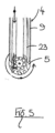
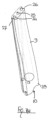
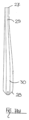
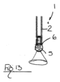
第一の態様によれば、耳の内部を検査するためのスコープであって、耳の内部構造への挿入のための細長いプローブ体によって形成されたプローブと、ハウジング内に位置する画像センサを含むカメラとを含み、前記ハウジングが前記プローブ体の遠位端に回転可能に結合されることにより、前記カメラが前記プローブ体に対して回転可能である、スコープが提供される。
SUMMARY OF THE DISCLOSURE According to a first aspect, there is provided a scope for examining the inside of an ear, comprising a probe formed by an elongated probe body for insertion into an internal structure of the ear, and a camera including an image sensor located in a housing, the housing being rotatably coupled to a distal end of the probe body such that the camera is rotatable relative to the probe body.
前記ハウジングは、前記ハウジングの回転が前記カメラの対応する回転を生じるように前記カメラの一部を形成している。本願において前記ハウジングの回転というときはいつでも、前記カメラの対応する回転をもたらすことと解釈することができる。 The housing forms a part of the camera such that rotation of the housing causes a corresponding rotation of the camera. Any reference in this application to rotation of the housing can be interpreted as causing a corresponding rotation of the camera.
前記回転可能なカメラの外表面は、前記スコープの外部露出表面を形成することができる。当該外表面は使用時に露出している。 The outer surface of the rotatable camera may form the outer exposed surface of the scope, which is exposed in use.
前記画像センサは、前記スコープの前記外部露出表面を形成する前記回転可能なカメラの前記外表面を通して可視化するように構成することができる。前記画像センサが前記回転可能なカメラの前記外表面を通して可視化するように構成することができる場合の前記外表面は、当該外表面と前記プローブ体の間のクリアランスを維持し、当該外表面と前記プローブ体の間の相対運動を可能にするように前記プローブ体から離間させることができ、前記カメラは、好ましくは、その回転軸を中心に360°回転するように構成される。 The image sensor may be configured to visualize through the outer surface of the rotatable camera that forms the external exposed surface of the scope. The outer surface, where the image sensor may be configured to visualize through the outer surface of the rotatable camera, may be spaced from the probe body to maintain a clearance between the outer surface and the probe body and to allow relative movement between the outer surface and the probe body, and the camera is preferably configured to rotate 360° about its axis of rotation.
前記カメラの少なくとも一部は、前記プローブ体の前記遠位端を越えて遠位側に配設することができる。 At least a portion of the camera may be disposed distally beyond the distal end of the probe body.
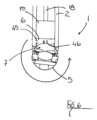
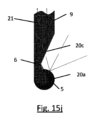
前記プローブ体は、前記プローブ体の前記遠位端から遠位方向に延出した、前記ハウジングを支持する一つまたは複数のタブを含むことができる。 The probe body may include one or more tabs extending distally from the distal end of the probe body to support the housing.
前記一つまたは複数のタブは一対のタブを含むことができる。当該一対のタブは、前記プローブ体の中心縦軸を中心に互いに反対側にあることができる。前記ハウジングが回転することができる回転軸は前記タブ間に延在することができる。 The one or more tabs may include a pair of tabs. The pair of tabs may be on opposite sides of a central longitudinal axis of the probe body. An axis of rotation about which the housing can rotate may extend between the tabs.
前記一対のタブ間には、少なくとも一つの遠位側に開いたノッチを画定することができる。当該少なくとも一つのノッチは、前記タブに対して前記プローブ体の前記遠位端の切欠部を形成することができる。これにより、前記カメラの視界を増大することが可能になる。具体的には、前記ノッチは、前記カメラが、近位側コンポーネントを有する方向を指向する(例えば、前記プローブの前記近位端に戻る方向に、前記プローブの縦軸に対して垂直よりも大きい)視野角を有する遮蔽されない視野を有することができるように構成することができる。 At least one distally opening notch can be defined between the pair of tabs. The at least one notch can form a cutout of the distal end of the probe body relative to the tabs, thereby enabling the camera to have an increased field of view. Specifically, the notch can be configured to enable the camera to have an unobstructed field of view with a viewing angle pointing toward a proximal component (e.g., toward the proximal end of the probe and greater than perpendicular to the longitudinal axis of the probe).
前記一対のタブ間の前記プローブ体の両側には、一対のノッチを画定することができ、当該ノッチは、前記回転軸に実質的に垂直な軸上で互いに整列している。 A pair of notches may be defined on either side of the probe body between the pair of tabs, the notches being aligned with one another on an axis substantially perpendicular to the axis of rotation.
前記カメラの一部は、前記ノッチまたは複数のノッチによって形成された前記プローブ体の部分を越えて遠位側に延在することができる。 A portion of the camera can extend distally beyond the portion of the probe body formed by the notch or notches.
前記一つまたは複数のタブは単一のタブを含むことができ、当該単一のタブは、前記カメラの前記回転軸に沿って片持ち梁配置で前記カメラを支持するように構成されている。 The one or more tabs may include a single tab configured to support the camera in a cantilever arrangement along the axis of rotation of the camera.
前記ハウジングは、前記ハウジングの回転軸に沿って延在する一つまたは複数の軸ピンのそれぞれを介して前記一つまたは複数のタブに回転可能に結合することができ、例えば、各タブは、対応する軸ピンを有する。 The housing may be rotatably coupled to the one or more tabs via one or more respective axle pins extending along a rotational axis of the housing, e.g., each tab having a corresponding axle pin.
前記一つまたは複数の軸ピンの各々は、前記カメラから始まり、前記それぞれのタブ上の受部内で終わることができる。あるいは、前記軸ピンの各々は、前記それぞれのタブから始まり、前記カメラハウジング内の受部内で終わる。ピンおよび受部の配置は逆にすることができ、したがって、各々は、前記カメラまたはプローブ上に設けることができる。 Each of the one or more axial pins can originate from the camera and terminate in a receptacle on the respective tab. Alternatively, each of the axial pins can originate from the respective tab and terminate in a receptacle within the camera housing. The pin and receptacle arrangement can be reversed, so that each can be provided on the camera or on the probe.
各軸ピンは、前記画像センサに電力を送るために前記ハウジング内の前記画像センサに電気的に結合された電気コンタクトを含むことができる。 Each axis pin may include an electrical contact electrically coupled to the image sensor within the housing to deliver power to the image sensor.
前記画像センサは画像データを生成するように構成することができ、当該生成された画像データは、前記軸ピンのうちの少なくとも一つを介して伝送される。電力および画像データは、前記軸ピンのうちの同一の軸ピンによって伝送することができる。 The image sensor can be configured to generate image data, and the generated image data can be transmitted through at least one of the axial pins. Power and image data can be transmitted through the same one of the axial pins.
前記プローブは、前記カメラに電力をワイヤレスで伝送するように構成することができる。前記プローブは、一つまたは複数の近距離ワイヤレス電力伝送コンポーネント(例えば、一つまたは複数の誘導コイル)を含むことができ、前記カメラは、一つまたは複数の対応する近距離受信コンポーネント(例えば、一つまたは複数の誘導コイル)を含み、互いの間で電力を転送するように構成される。 The probe can be configured to wirelessly transmit power to the camera. The probe can include one or more short-range wireless power transmission components (e.g., one or more induction coils) and the camera can include one or more corresponding short-range receiving components (e.g., one or more induction coils) configured to transfer power between each other.
前記一つまたは複数の近距離電力伝送/受信コンポーネントのうちの一つは、前記一つまたは複数の軸ピンのうちの少なくとも一つの中に位置することができ、少なくとも一つの対応するワイヤレス電力伝送/受信コンポーネントが、前記軸ピンまたは複数の軸ピン用の前記それぞれの受部内、例えば、前記カメラまたは前記それぞれのタブ内に位置する。この配置は、電力を運び得るコンポーネントとの流体の潜在的な接触を防止するためである。 One of the one or more short-range power transmission/reception components can be located within at least one of the one or more axial pins, and at least one corresponding wireless power transmission/reception component is located within the respective receiving portion for the axial pin or pins, e.g., the camera or the respective tab. This arrangement is to prevent potential fluid contact with components that may carry power.
前記近距離ワイヤレス電力伝送/受信コンポーネントはさらに、電力に加えて前記プローブと前記カメラの間でデータを伝送するように構成される。 The short-range wireless power transmission/reception component is further configured to transmit data between the probe and the camera in addition to power.
前記スコープは、前記カメラに結合されたデータケーブルをさらに含むことができる。 The scope may further include a data cable coupled to the camera.
前記画像センサは、画像データを生成するように構成することができる。当該生成された画像データは、前記ケーブルを介して伝送することができる。 The image sensor can be configured to generate image data. The generated image data can be transmitted via the cable.
前記プローブ体は内部チャネルを含むことができる。 The probe body may include an internal channel.
前記内部チャネルは、前記カメラを保持するために前記内部チャネルの遠位端に開放口部を形成することができ、前記ハウジングは、当該開放口部内に部分的に受容される。 The internal channel may define an open mouth at a distal end thereof for holding the camera, and the housing may be partially received within the open mouth.
前記スコープは、一つまたは複数の自己清掃モジュールをさらに含むことができる。当該自己清掃モジュールのうちの少なくとも一つは清掃要素を含むことができ、前記カメラは、当該清掃要素に対して回転可能である。これにより、前記清掃要素は、使用中に露出する前記カメラの前記外表面を清掃することが可能になる。 The scope may further include one or more self-cleaning modules. At least one of the self-cleaning modules may include a cleaning element, and the camera may be rotatable relative to the cleaning element, thereby enabling the cleaning element to clean the exterior surface of the camera that is exposed during use.
前記清掃要素は、前記カメラに対して近位側に配置することができる。前記清掃要素は、前記カメラに対して遠位側に配置することを含む、前記カメラに対する別の適した位置を有することができる。 The cleaning element can be positioned proximally relative to the camera. The cleaning element can have other suitable positions relative to the camera, including being positioned distally relative to the camera.
前記または各々の清掃モジュールの前記清掃要素は、前記プローブへの装着によって所定の位置に固定することができ、前記カメラの回転軸によって画定される前記カメラの円周に沿う任意の地点で前記回転可能なカメラと係合するように構成される。 The cleaning element of the or each cleaning module can be fixed in position by attachment to the probe and is configured to engage the rotatable camera at any point along the circumference of the camera defined by the axis of rotation of the camera.
前記自己清掃モジュールのうちの少なくとも一つは、前記プローブに対して可動な清掃要素を含むことができ、当該可動清掃要素は、好ましくは、ブラシなどの回転要素であり、当該可動清掃要素は、任意選択で、独立してまたはカメラ向き付け機構と連絡して回転される。 At least one of the self-cleaning modules may include a cleaning element that is movable relative to the probe, preferably a rotating element such as a brush, which is optionally rotated independently or in communication with a camera orientation mechanism.
前記清掃要素は、前記プローブ体の前記内部チャネル内に配設することができる。 The cleaning element may be disposed within the internal channel of the probe body.
前記清掃要素は、前記カメラに対して側方にオフセット(例えば、前記プローブ体の前記縦軸に対して垂直な方向にオフセット)していることができる。 The cleaning element may be laterally offset relative to the camera (e.g., offset perpendicular to the longitudinal axis of the probe body).
前記清掃要素は、前記一対のタブ間に配設することができる。 The cleaning element can be disposed between the pair of tabs.
前記カメラは、レンズを含む光学構成を備えることができ、前記画像センサは、当該レンズを通して受けた光から画像データを生成するように構成される。 The camera may have an optical arrangement including a lens, and the image sensor is configured to generate image data from light received through the lens.
前記光学構成は、前記ハウジングの一部を形成する窓をさらに含み、当該窓が、前記画像センサと当該窓の間に光路が画定され、当該光路が前記レンズを通って延在するように、前記画像センサおよび前記レンズと整列する。 The optical arrangement further includes a window forming part of the housing, the window aligned with the image sensor and the lens such that an optical path is defined between the image sensor and the window, the optical path extending through the lens.
前記窓の内表面と前記レンズの外表面の間には、流体充填間隙を画定することができる。当該流体充填間隙は空気充填間隙とすることができる。 A fluid-filled gap may be defined between the inner surface of the window and the outer surface of the lens. The fluid-filled gap may be an air-filled gap.
前記光学構成は、前記レンズを合焦させるための合焦機構をさらに含むことができる。前記合焦機構は、前記レンズと前記画像センサの間に相対運動をもたらすことができる。 The optical arrangement may further include a focusing mechanism for focusing the lens. The focusing mechanism may provide relative motion between the lens and the image sensor.
前記合焦機構は、前記レンズを合焦させるように構成された形状記憶金属コンポーネントを含むことができる。 The focusing mechanism may include a shape memory metal component configured to focus the lens.
前記合焦機構は、電気機械的に動作され、好ましくは微小電気機械システムを含む。 The focusing mechanism is electromechanically operated and preferably includes a microelectromechanical system.
前記合焦機構は、合焦レンズを含むことができ、当該合焦レンズと前記画像センサの間の距離が変化するように当該合焦レンズと前記画像センサの間の相対運動をもたらすように該合焦レンズまたは前記画像センサを振動させるように構成することができる。前記スコープ、または前記スコープに結合されたデータ処理システムは、合焦画像を生成するために前記結果的に生じる画像データをサンプリングするように構成することができる。当該画像データは、前記レンズの可動域に沿った所望の焦点に対応するフレームを選択することによってサンプリングすることができる。 The focusing mechanism may include a focusing lens and may be configured to vibrate the focusing lens or the image sensor to provide relative motion between the focusing lens and the image sensor such that a distance between the focusing lens and the image sensor changes. The scope, or a data processing system coupled to the scope, may be configured to sample the resulting image data to generate a focused image. The image data may be sampled by selecting a frame corresponding to a desired focus along a range of motion of the lens.
前記振動可能な合焦レンズ/画像センサを使用して、前記カメラの外表面(例えば、前記レンズまたは窓)の清掃をもたらすことができる。前記合焦機構は、切替可能なダンパによって前記カメラの前記外表面に選択的に機械的に結合することができる。当該ダンパは、任意選択で、前記合焦機構の振動が減衰される減衰状態と、前記合焦機構の振動が前記カメラの前記外表面に伝達されるロック状態との間で切替可能とすることができる。 The vibrable focusing lens/image sensor can be used to provide cleaning of the exterior surface of the camera (e.g., the lens or window). The focusing mechanism can be selectively mechanically coupled to the exterior surface of the camera by a switchable damper. The damper can optionally be switchable between a damped state in which vibrations of the focusing mechanism are damped, and a locked state in which vibrations of the focusing mechanism are transmitted to the exterior surface of the camera.
前記合焦機構は、前記カメラの前記外部レンズまたは窓の共振周波数と略同じ周波数で前記合焦レンズ/画像センサを振動させるように構成することができる。前記合焦機構は、前記合焦レンズおよび/または画像センサの振動の周波数を、前記カメラの前記レンズまたは窓の共振周波数とは異なる第一の周波数と、前記外部レンズまたは窓の共振周波数と略同じ第二の周波数との間で切り替えるように構成することができる。 The focusing mechanism may be configured to vibrate the focusing lens/image sensor at a frequency approximately equal to a resonant frequency of the external lens or window of the camera. The focusing mechanism may be configured to switch the frequency of vibration of the focusing lens and/or image sensor between a first frequency different from the resonant frequency of the lens or window of the camera and a second frequency approximately equal to the resonant frequency of the external lens or window.
前記合焦レンズ/画像センサの前記振動は、前記カメラの前記レンズまたは窓を横断する清掃気流を生成するように構成することができる。前記カメラは一つまたは複数の通気口を含むことができる。当該通気口は、前記合焦レンズ/画像センサの前記振動から生じる前記カメラ内の圧力変化によって生成される空気の流れをもたらすように構成することができる。前記通気口は、前記カメラの前記外表面を形成する前記レンズまたは窓に隣接配置することができる。前記通気口は、前記カメラの前記外表面を形成する前記レンズまたは窓を通って延在する貫通孔によって形成することができる。 The vibration of the focusing lens/image sensor may be configured to generate a cleaning airflow across the lens or window of the camera. The camera may include one or more vents. The vents may be configured to provide an airflow generated by pressure changes within the camera resulting from the vibration of the focusing lens/image sensor. The vents may be located adjacent to the lens or window forming the exterior surface of the camera. The vents may be formed by through holes extending through the lens or window forming the exterior surface of the camera.
前記カメラは、前記カメラの前記外表面から、例えば、前記カメラの中に伝達される光が通る前記レンズまたは窓の外表面から延出したまつげの形をした複数の可動清掃部材を含む。 The camera includes a plurality of movable cleaning members in the form of eyelashes extending from the exterior surface of the camera, for example from the exterior surface of the lens or window through which light is transmitted into the camera.
前記まつげは、デブリを前記画像センサの視野から消すように前記カメラの表面上を移動させるように前記カメラの前記外表面に対して動くように構成することができる。 The eyelashes can be configured to move relative to the exterior surface of the camera to move debris over the surface of the camera to remove it from the field of view of the image sensor.
前記プローブは、前記カメラに隣接した前記プローブ体の表面上に配置された複数の可動清掃部材を含むことができる。当該可動清掃部材は、デブリを前記プローブ体の当該表面上を移動させるように前記プローブ体に対して動くように構成することができる。前記複数の可動清掃部材はまつげの形をしていることができる。前記プローブは、前記まつげによって集められた物質を除去するように構成された吸引システムをさらに含むことができる。 The probe may include a plurality of movable cleaning members disposed on a surface of the probe body adjacent to the camera. The movable cleaning members may be configured to move relative to the probe body to move debris over the surface of the probe body. The plurality of movable cleaning members may be in the form of eyelashes. The probe may further include a suction system configured to remove material collected by the eyelashes.
前記プローブ体またはカメラは、前記可動清掃部材に清掃流体源を提供するように構成された清掃流体供給装置をさらに含むことができる。 The probe body or camera may further include a cleaning fluid supply device configured to provide a source of cleaning fluid to the movable cleaning member.
前記カメラは、前記画像センサによって生成された画像データを伝送および/または受信するように構成された通信モジュールを含むことができる。 The camera may include a communications module configured to transmit and/or receive image data generated by the image sensor.
前記通信モジュールは、2.4GHz以上の周波数で画像データを伝送および/または受信するように構成することができる。前記カメラは、前記プローブにワイヤレスで前記画像センサから生の画像データを送信するように構成することができる。前記カメラは、プロセッサと、アンテナと通信しているRFユニットとを含むことができる。この実施形態では、前記カメラは、画像処理電子装置を含まないことによって、前記プローブから前記カメラへの前記画像データの伝送のための電子装置を最小限にすることができる。これにより、前記カメラのサイズを最小化することが可能になる。他の実施形態では、画像処理を前記カメラ内で行うことができる。 The communication module may be configured to transmit and/or receive image data at frequencies of 2.4 GHz or higher. The camera may be configured to transmit raw image data from the image sensor wirelessly to the probe. The camera may include a processor and an RF unit in communication with an antenna. In this embodiment, the camera may not include image processing electronics, thereby minimizing electronics for the transmission of the image data from the probe to the camera. This allows the size of the camera to be minimized. In other embodiments, image processing may occur within the camera.
前記プローブ上の前記通信モジュールは、前記生の画像データを処理するためにビデオ処理ユニットを含むことができる。当該ビデオ処理ユニットは、好ましくは長距離にわたって伝送可能であるか、または直ぐに利用可能なソフトウェアによって解釈されるアルゴリズムを用いて、前記生の画像データを圧縮するように構成することができる。 The communications module on the probe may include a video processing unit to process the raw image data. The video processing unit may be configured to compress the raw image data using algorithms that are preferably transmittable over long distances or interpreted by readily available software.
前記カメラ通信モジュールは、前記プローブ内の通信モジュールとの間でデータをワイヤレスで伝送または受信するように構成することができる。前記プローブ内に設けられた前記通信モジュールは、前記カメラから30mm未満にあることができる。 The camera communication module can be configured to wirelessly transmit or receive data to or from a communication module in the probe. The communication module in the probe can be less than 30 mm from the camera.
前記カメラワイヤレス通信モジュールは、全指向性アンテナ(例えば、モノポールアンテナ)を含むアンテナシステムを含むことができ、前記プローブ通信モジュールは、単一指向性アンテナを含むアンテナシステムを含むことができる。 The camera wireless communication module may include an antenna system including an omnidirectional antenna (e.g., a monopole antenna), and the probe communication module may include an antenna system including a unidirectional antenna.
前記カメラワイヤレス通信モジュールは、モノポールアンテナを含むアンテナシステムを含むことができ、前記プローブ通信モジュールは、全指向性アンテナ(例えば、モノポールアンテナ)を含むアンテナシステムを含むことができる。 The camera wireless communication module may include an antenna system including a monopole antenna, and the probe communication module may include an antenna system including an omnidirectional antenna (e.g., a monopole antenna).
前記カメラワイヤレス通信モジュールは、異なる向きを有する二つ以上の指向性アンテナを含むアンテナシステムを含むことができ、前記プローブ通信モジュールは、単一指向性アンテナを含むアンテナシステムを含むことができる。前記カメラ内に設けられた前記二つ以上の単一指向性アンテナは、前記プローブに対する前記カメラの向きに応じて選択的に動作させることができる。前記カメラに設けられた前記二つ以上の単一指向性アンテナは、前記プローブに対する前記カメラの向きに応じて選択的に動作させることができる。前記カメラは、前記カメラ内から感知された方向データを用いて前記プローブに前記データを伝送するために最も有利な(例えば最も近い)アンテナを選択するように構成することができる。前記カメラは、当該最も有利なアンテナ以外の他のアンテナをオフにするように構成することができる。 The camera wireless communication module may include an antenna system including two or more directional antennas having different orientations, and the probe communication module may include an antenna system including a unidirectional antenna. The two or more unidirectional antennas provided in the camera may be selectively operated depending on the orientation of the camera relative to the probe. The two or more unidirectional antennas provided in the camera may be selectively operated depending on the orientation of the camera relative to the probe. The camera may be configured to select a most advantageous (e.g., closest) antenna for transmitting the data to the probe using directional data sensed from within the camera. The camera may be configured to turn off other antennas other than the most advantageous antenna.
前記カメラは、前記ワイヤレス通信モジュールを介して前記カメラから前記プローブへ生の(すなわち未処理の)画像データを伝送するように構成することができる。これは、前記カメラ内で画像処理がほとんどまたは全く行われないことを意味し、前記カメラをより小さくすることが可能である。 The camera can be configured to transmit raw (i.e. unprocessed) image data from the camera to the probe via the wireless communication module. This means that little or no image processing takes place in the camera, allowing the camera to be smaller.
前記プローブの前記アンテナシステムと前記カメラの前記アンテナシステムの間の伝送距離は、25mm未満、好ましくは5mmから10mmの間とすることができる。 The transmission distance between the antenna system of the probe and the antenna system of the camera can be less than 25 mm, preferably between 5 mm and 10 mm.
前記スコープは、前記カメラに組み込まれた光源をさらに含むことができる。 The scope may further include a light source integrated into the camera.
前記光源は、前記プローブ体に対して前記画像センサとともに可動とすることができる。 The light source can be movable along with the image sensor relative to the probe body.
前記プローブは、前記画像センサの視野を照らすための光源をさらに含むことができる。 The probe may further include a light source for illuminating the field of view of the image sensor.
前記スコープは、前記プローブ体に対する前記ハウジングの回転運動を制御するように構成された向き付け機構を含むことができる。 The scope may include an orientation mechanism configured to control rotational movement of the housing relative to the probe body.
前記向き付け機構はベルト式向き付け機構を含むことができる。当該ベルト式向き付け機構は、前記プローブの近位端に配置された駆動シャフトと前記ハウジングに作用する従動シャフトとに結合された駆動ベルトを含むことができる。 The orientation mechanism may include a belt-type orientation mechanism. The belt-type orientation mechanism may include a drive belt coupled to a drive shaft disposed at the proximal end of the probe and a driven shaft acting on the housing.
前記駆動ベルトは、前記駆動シャフトおよび/または前記従動シャフトの周りを少なくとも二周するように巻き付けることができる。 The drive belt can be wrapped around the drive shaft and/or the driven shaft at least twice.
前記駆動シャフトは、前記駆動シャフトを回転させるためのステッピングモータに動作可能に結合することができる。 The drive shaft may be operably coupled to a stepper motor for rotating the drive shaft.
前記向き付け機構は、前記ハウジングの遠位側の二つの装着地点に結合された少なくとも一つのケーブルを含むことができ、当該装着地点は、前記ハウジングの回転軸を中心に互いに反対側にある。 The orientation mechanism may include at least one cable coupled to two attachment points on the distal side of the housing, the attachment points being on opposite sides of the housing's axis of rotation.
前記向き付け機構は、第一の方向の前記カメラの回転をもたらすように構成された第一のケーブルと、前記回転軸を中心とする第二の方向の回転をもたらすように構成された第二のケーブルとを含むことができる。当該第一および第二のケーブルは、(当該第一および第二のケーブルが前記カメラの前記外表面上の一地点から延出するように)前記カメラに接続または前記カメラ内で接続され、前記カメラの前記ハウジング周りに前記カメラの前記回転軸を中心に反対方向に延在することができる。 The orientation mechanism may include a first cable configured to effect rotation of the camera in a first direction and a second cable configured to effect rotation in a second direction about the axis of rotation. The first and second cables may be connected to or within the camera (such that the first and second cables extend from a point on the exterior surface of the camera) and extend in opposite directions around the housing of the camera about the axis of rotation of the camera.
前記少なくとも一つのケーブルまたは第一のおよび第二のケーブルは、好ましくは互いに対して(例えば前記回転軸に垂直な)異なる平面内で、前記回転軸によって画定される前記カメラの円周上の同じ地点で前記カメラに進入することができる。 The at least one cable or the first and second cables may enter the camera at the same point on the circumference of the camera defined by the axis of rotation, preferably in different planes relative to each other (e.g. perpendicular to the axis of rotation).
前記ケーブルまたは複数のケーブルは、前記画像センサが前記プローブの縦軸に沿って遠位方向を指向する中心位置から前記カメラの前記回転軸周りにいずれの方向にも175度を超える回転をもたらすように構成することができる。 The cable or cables can be configured to provide rotation of the camera about the axis of rotation of greater than 175 degrees in either direction from a central position in which the image sensor points distally along the longitudinal axis of the probe.
前記第一のケーブルは前記カメラの第一の側部の周りに延在することができ、前記第二のケーブルは前記カメラの第二の側部の周りに延在し、前記第一のケーブルは、前記カメラの前記第二の側部に対応する前記プローブ体の側部に位置する前記プローブ体内のチャネルから延出し、前記第二のケーブルは、前記カメラの前記第一の側部に対応する前記プローブ体の側部に位置する前記プローブ体内のチャネルから延出する。 The first cable can extend around a first side of the camera, the second cable can extend around a second side of the camera, the first cable extending from a channel in the probe body located on a side of the probe body corresponding to the second side of the camera, and the second cable extending from a channel in the probe body located on a side of the probe body corresponding to the first side of the camera.
前記第一および第二のケーブルは、前記カメラ上の同じ地点(すなわち前記回転軸に対して前記カメラの前記円周周りの同じ地点)から延出することができる。前記第一および第二のケーブルは、前記カメラの前記遠位側から延出することができる(例えば、前記第一および第二のケーブルは、前記カメラが、前記画像センサが前記プローブ体の前記縦軸に沿って前記遠位方向を指向する非回転位置、すなわちゼロ度位置にあるときに、前記カメラ/ハウジングの最も遠位側の地点から延出することができる)。 The first and second cables can extend from the same point on the camera (i.e., the same point around the circumference of the camera relative to the axis of rotation). The first and second cables can extend from the distal side of the camera (e.g., the first and second cables can extend from the distal-most point of the camera/housing when the camera is in a non-rotated, i.e., zero degree, position in which the image sensor points in the distal direction along the longitudinal axis of the probe body).
前記第一のケーブルは、前記回転軸に対して第一の側部の前記カメラ上の地点から延出し、前記カメラの反対側の第二の側部の周りで前記カメラの周りに延在することができる。前記第二のケーブルは、前記第二の側部の地点から延出し、反対方向に前記第一の側部の周りに延在することができる。これにより、前記回転軸を中心とする前記カメラの360度の回転を可能にすることができる。 The first cable may extend from a point on the camera on a first side relative to the axis of rotation and extend around the camera around a second side opposite the camera. The second cable may extend from a point on the second side and extend around the first side in the opposite direction. This may allow 360 degree rotation of the camera about the axis of rotation.
前記記載における前記少なくとも一つのケーブルまたは複数のケーブル(第一および第二のケーブル)は、前記画像センサに電力を送るために前記ハウジング内で前記画像センサに電気的に接続することができる。 The at least one cable or cables (first and second cables) in the above description can be electrically connected to the image sensor within the housing to transmit power to the image sensor.
前記記載における前記少なくとも一つのケーブルまたは複数のケーブル(第一および第二のケーブル)は、前記画像センサによって生成された画像データを伝送するために前記画像センサに接続することができる。これらは、電力とデータの両方を運ぶことができる。 The at least one cable or cables (first and second cables) in the above description can be connected to the image sensor to transmit image data generated by the image sensor. They can carry both power and data.
これにより、前記向き付け機構が、他の接続部/ワイヤレス通信を必要とすることなく、前記カメラの作動とデータ/電力伝送の両方を提供することを可能にすることができる。 This allows the orientation mechanism to provide both operation of the camera and data/power transmission without the need for other connections/wireless communications.
前記カメラは、その回転軸を中心とする均一な輪郭を有することができる。前記カメラは、その回転軸を通る断面を実質的に円形とすることができる。当該断面は、他の実施形態では、円柱形とすることができる。前記カメラは、概して球形とすることができる。前記カメラは、前記回転軸を通って測定される6.5mm未満の円周を有することができる。前記カメラは、前記回転軸を通って測定される3.5mm未満の円周を有することができる。 The camera may have a uniform profile about its axis of rotation. The camera may be substantially circular in cross section through its axis of rotation. In other embodiments, the cross section may be cylindrical. The camera may be generally spherical. The camera may have a circumference measured through the axis of rotation of less than 6.5 mm. The camera may have a circumference measured through the axis of rotation of less than 3.5 mm.
前記プローブは、前記ビジュアライザに電力をワイヤレスで伝送するように構成することができる。前記プローブは、一つまたは複数の誘導コイルを含むことができ、前記カメラは、互いの間で電力を転送するように構成された一つまたは複数の誘導コイルを含むことができる。当該誘導コイルは、誘導結合によってエネルギーを転送するように構成することができる。前記プローブに設けられた前記一つまたは複数の誘導コイルは、前記カメラを支持する前記タブ内に配置することができる。前記カメラに設けられた前記一つまたは複数の誘導コイルは、前記カメラの前記軸ピン内に配置することができる。 The probe can be configured to wirelessly transmit power to the visualizer. The probe can include one or more induction coils and the camera can include one or more induction coils configured to transfer power between each other. The induction coils can be configured to transfer energy by inductive coupling. The one or more induction coils on the probe can be positioned within the tab that supports the camera. The one or more induction coils on the camera can be positioned within the axial pin of the camera.
前記スコープは、患者の耳に挿入するためのスペキュラをさらに含むことができ、前記プローブ体は、当該スペキュラに対して可動である。 The scope may further include a specular for insertion into the patient's ear, and the probe body is movable relative to the specular.
第二の態様によれば、患者の耳の内部構造を検査する方法であって、
前記耳の内部構造にプローブを挿入するステップであって、当該プローブがハウジング内に配設された画像センサを含むカメラを支持する細長いプローブ体によって形成され、前記ハウジングが、前記プローブ体の遠位端に回転可能に結合されることにより、前記カメラが前記プローブ体に対して回転可能である、ステップと、
前記耳の内部構造に対して前記画像センサの回転運動を生じるように前記プローブ体に対して前記ハウジングを回転させるステップとを含み、
前記ハウジングを回転させるステップが、前記回転運動中ずっと前記耳の内部構造を観視しながら前記プローブ体に対して前記ハウジングを少なくとも90°回転させるステップを含む、方法が提供される。
According to a second aspect, there is provided a method of examining an internal structure of a patient's ear, comprising the steps of:
inserting a probe into the internal structure of the ear, the probe being formed by an elongated probe body supporting a camera including an image sensor disposed in a housing, the housing being rotatably coupled to a distal end of the probe body such that the camera is rotatable relative to the probe body;
and rotating the housing relative to the probe body to cause rotational movement of the image sensor relative to the internal structure of the ear;
A method is provided in which rotating the housing includes rotating the housing at least 90 degrees relative to the probe body while viewing the internal structure of the ear throughout the rotational movement.
前記回転可能なカメラの外表面が、前記スコープの外部露出表面を形成することができる。当該外表面は、使用中に露出している。 The outer surface of the rotatable camera may form the outer exposed surface of the scope, which is exposed during use.
前記方法は、前記画像センサが遠位方向を向いた第一の位置から、前記画像センサが近位方向を向いた第二の位置まで前記カメラを回転させるステップを含むことができる。 The method may include rotating the camera from a first position in which the image sensor faces distally to a second position in which the image sensor faces proximally.
前記方法は、前記カメラ(およびハウジング)を回転させて前記第一の位置に戻すステップをさらに含むことができる。 The method may further include rotating the camera (and housing) back to the first position.
前記カメラを前記第一の位置から前記第二の位置まで回転させ、前記第一の位置に戻すステップは、前記カメラ(およびハウジング)を360°回転させるステップを含むことができる。 The step of rotating the camera from the first position to the second position and back to the first position may include rotating the camera (and housing) 360 degrees.
前記カメラを回転させるステップは、前記画像センサが前記プローブの縦軸に沿って遠位方向を指向する中心位置から前記カメラの回転軸周りのいずれの方向にも175度を超える範囲にわたって前記カメラを回転させるステップを含むことができる。 The step of rotating the camera may include rotating the camera from a central position in which the image sensor points distally along the longitudinal axis of the probe through a range of greater than 175 degrees in either direction about the axis of rotation of the camera.
前記カメラを回転させるステップが、第一の方向の前記カメラの回転をもたらすように構成された第一のケーブルと、前記回転軸を中心とする第二の方向の回転をもたらすように構成された第二のケーブルとを含む向き付け機構を用いて前記カメラを回転させるステップを含むことができ、好ましくは、前記第一および第二のケーブルは、前記カメラにまたは前記カメラ内で接続され、前記カメラの前記ハウジング周りに前記カメラの前記回転軸を中心に反対方向に延在する。 The step of rotating the camera may include rotating the camera using an orientation mechanism including a first cable configured to effect rotation of the camera in a first direction and a second cable configured to effect rotation in a second direction about the axis of rotation, preferably the first and second cables are connected to or within the camera and extend in opposite directions around the housing of the camera about the axis of rotation of the camera.
前記第一のケーブルは、前記カメラの第一の側部の周りに延在することができ、前記第二のケーブルは前記カメラの第二の側部の周りに延在し、当該第一のケーブルは、前記カメラの前記第二の側部に対応する前記プローブ体の側部に位置する前記プローブ体内のチャネルから延出し、当該第二のケーブルは、前記カメラの前記第一の側部に対応する前記プローブ体の側部に位置する前記プローブ体内のチャネルから延出する。 The first cable can extend around a first side of the camera, the second cable can extend around a second side of the camera, the first cable extending from a channel in the probe body located on a side of the probe body corresponding to the second side of the camera, and the second cable extending from a channel in the probe body located on a side of the probe body corresponding to the first side of the camera.
前記方法は、前記カメラの外表面を清掃するステップを含むことができる。 The method may include cleaning an exterior surface of the camera.
前記カメラの前記外表面を清掃するステップは、清掃要素に対して前記カメラ(およびハウジング)を回転させるステップを含むことができる。 Cleaning the exterior surface of the camera may include rotating the camera (and housing) relative to a cleaning element.
前記清掃要素に対して前記カメラ(およびハウジング)を回転させるステップは、前記清掃要素で前記カメラの外表面を拭うステップを含むことができる。 The step of rotating the camera (and housing) relative to the cleaning element may include wiping an exterior surface of the camera with the cleaning element.
前記カメラは、前記光センサと整列したレンズを含むことができ、当該方法は、当該レンズを合焦するステップを含む。 The camera may include a lens aligned with the light sensor, and the method includes focusing the lens.
前記カメラを回転させるステップは、前記プローブ体に対して前記ハウジングを少なくとも120°回転させるステップを含むことができる。 The step of rotating the camera may include rotating the housing at least 120° relative to the probe body.
第三の態様によれば、耳の内部を検査するためのスコープを清掃する方法において、当該スコープが、回転可能なハウジング内に配設された画像センサを含み、当該スコープが清掃要素をさらに含む方法であって、前記清掃要素に対して前記ハウジングを回転させるステップと、前記清掃要素を用いて前記ハウジングの外表面を清掃するステップとを含む方法が提供される。 According to a third aspect, there is provided a method of cleaning a scope for inspecting the inside of an ear, the scope including an image sensor disposed in a rotatable housing, the scope further including a cleaning element, the method including the steps of rotating the housing relative to the cleaning element, and cleaning an exterior surface of the housing with the cleaning element.
前記ハウジングの前記外表面を清掃するステップが、前記清掃要素に対して前記ハウジングを回転させることによって前記清掃要素で前記ハウジングを拭うステップを含むことができる。 Cleaning the exterior surface of the housing may include wiping the housing with the cleaning element by rotating the housing relative to the cleaning element.
前記ハウジングを回転させるステップは、前記光センサが遠位方向に向いた第一の位置から、前記光センサが近位方向に向いた第二の位置まで前記ハウジングを回転させるステップを含むことができる。 The step of rotating the housing may include rotating the housing from a first position in which the optical sensor faces distally to a second position in which the optical sensor faces proximally.
前記方法は、前記第一の位置まで前記ハウジングを戻すステップをさらに含むことができる。 The method may further include returning the housing to the first position.
前記ハウジングを回転させるステップは、前記プローブ体の中心縦軸を横断する前記ハウジングの回転軸を中心に前記ハウジングを360°旋回させるステップを含むことができる。 The step of rotating the housing may include a step of pivoting the housing 360° about an axis of rotation of the housing that transverses a central longitudinal axis of the probe body.
前記ハウジングを回転させるステップは、前記光センサが遠位方向を向く第一の位置から、前記画像センサが前記プローブ体の中心縦軸に対して概して垂直に向いた第二の位置まで前記ハウジングを回転させるステップを含むことができる。 The step of rotating the housing may include rotating the housing from a first position in which the optical sensor faces distally to a second position in which the image sensor faces generally perpendicular to a central longitudinal axis of the probe body.
第四の態様によれば、患者の耳の内部構造を検査するためのカメラであって、前記耳の内部構造に挿入するためのロッドと、ハウジング内に位置する光センサとを含むカメラにおいて、前記ハウジングが、前記ロッドの遠位端に回転可能に結合され、前記ハウジングの少なくとも一部が、前記ロッドの前記遠位端を越えて遠位側に配設される、カメラが提供される。 According to a fourth aspect, there is provided a camera for inspecting an internal structure of a patient's ear, the camera including a rod for insertion into the internal structure of the ear and an optical sensor located within a housing, the housing being rotatably coupled to a distal end of the rod, and at least a portion of the housing being disposed distally beyond the distal end of the rod.
前記ロッドは、前記ロッドの前記遠位端から遠位方向に延出した、前記ハウジングを支持する一対のタブを含むことができる。 The rod may include a pair of tabs extending distally from the distal end of the rod to support the housing.
前記タブは、前記ロッドの中心縦軸を中心に互いに反対側にあることができ、前記ハウジングが回転することができる回転軸が当該タブ間に延在する。 The tabs may be opposed to one another about a central longitudinal axis of the rod, with an axis of rotation extending between the tabs about which the housing may rotate.
前記一対の支持タブ間には、少なくとも一つの遠位側に開いたノッチを画定することができる。 At least one distally opening notch may be defined between the pair of support tabs.
前記一対のタブ間で前記ロッドの両側には、一対のノッチを画定することができ、当該ノッチは、前記回転軸に実質的に垂直な軸上で互いに整列している。 A pair of notches may be defined on either side of the rod between the pair of tabs, the notches being aligned with one another on an axis substantially perpendicular to the axis of rotation.
前記ハウジングの一部は、前記タブの遠位端を越えて遠位側に延在することができる。 A portion of the housing may extend distally beyond the distal end of the tab.
前記ハウジングは、前記ハウジングの回転軸に沿って延在するピンを介して前記タブに回転可能に結合することができる。 The housing can be rotatably coupled to the tab via a pin that extends along the axis of rotation of the housing.
各ピンは、前記光センサに電力を送るために前記ハウジング内の前記光センサに電気的に結合された電気コンタクトを含むことができる。 Each pin may include an electrical contact electrically coupled to the light sensor within the housing to deliver power to the light sensor.
前記光センサは、画像データを生成するように構成することができ、当該生成された画像データは、前記ピンのうちの少なくとも一つを介して伝送される。 The optical sensor may be configured to generate image data, the generated image data being transmitted via at least one of the pins.
前記カメラは、前記ハウジングに結合されたデータケーブルをさらに含むことができる。 The camera may further include a data cable coupled to the housing.
前記光センサは、画像データを生成するように構成することができ、当該生成された画像データは前記ケーブルを介して伝送される。 The optical sensor can be configured to generate image data, which is transmitted via the cable.
前記ロッドは内部ルーメンを含むことができる。 The rod may include an internal lumen.
前記ハウジングは、前記内部ルーメン内に部分的に受容することができる。 The housing can be partially received within the inner lumen.
前記カメラは清掃要素をさらに含むことができ、前記ハウジングは当該清掃要素に対して回転可能である。 The camera may further include a cleaning element, and the housing may be rotatable relative to the cleaning element.
前記清掃要素は、前記ハウジングの近位側に配置することができる。 The cleaning element may be positioned proximal to the housing.
前記清掃要素は、前記ロッドの前記内部ルーメン内に配設することができる。 The cleaning element may be disposed within the internal lumen of the rod.
前記清掃要素は、前記ハウジングに対して側方にオフセットしていることができる。 The cleaning element may be offset laterally relative to the housing.
前記清掃要素は、前記一対のタブ間に配設することができる。 The cleaning element can be disposed between the pair of tabs.
前記ハウジングはレンズを含むことができ、前記光センサは、当該レンズを通して受ける光から画像データを生成するように構成される。 The housing may include a lens, and the light sensor is configured to generate image data from light received through the lens.
前記ハウジングは、窓であって、前記光センサと当該窓の間に前記レンズを通って延在する光路が画定されるように前記光センサおよび前記レンズと整列した窓をさらに含むことができる。 The housing may further include a window aligned with the light sensor and the lens such that an optical path is defined between the light sensor and the window, the optical path extending through the lens.
前記窓の内表面と前記レンズの外表面の間には、空隙を画定することができる。 A gap may be defined between the inner surface of the window and the outer surface of the lens.
前記ハウジングは、前記レンズを合焦させるための合焦機構を含むことができる。 The housing may include a focusing mechanism for focusing the lens.
前記合焦機構は、前記レンズを合焦させるように構成された形状記憶金属コンポーネントを含むことができる。 The focusing mechanism may include a shape memory metal component configured to focus the lens.
前記合焦機構は微小電気機械システムを含むことができる。 The focusing mechanism may include a microelectromechanical system.
前記ハウジングは、前記光センサによって生成された画像データを伝送および/または受信するように構成された通信モジュールを含むことができる。 The housing may include a communications module configured to transmit and/or receive image data generated by the optical sensor.
前記通信モジュールは、2.4GHz以上の周波数で画像データを伝送および/または受信するように構成することができる。 The communication module can be configured to transmit and/or receive image data at frequencies of 2.4 GHz or higher.
前記ハウジングは、前記光センサの視野を照らすための光源をさらに含むことができる。 The housing may further include a light source for illuminating the field of view of the optical sensor.
前記光源は、前記ロッドに対して前記光センサとともに可動とすることができる。 The light source can be movable along with the light sensor relative to the rod.
前記ロッドは、前記光センサの視野を照らすための光源をさらに含むことができる。 The rod may further include a light source for illuminating the field of view of the optical sensor.
前記カメラは、前記ロッドに対する前記ハウジングの前記回転運動を制御するように構成された向き付け機構を含むことができる。 The camera may include an orientation mechanism configured to control the rotational movement of the housing relative to the rod.
前記向き付け機構は、前記ロッドの近位端に配置された駆動シャフトと、前記ハウジングに作用する従動シャフトとに結合された駆動ベルトを含むことができる。 The orientation mechanism may include a drive belt coupled to a drive shaft disposed at a proximal end of the rod and a driven shaft acting on the housing.
前記駆動ベルトは、前記駆動シャフトおよび前記従動シャフトの周りに少なくとも二周巻き付けることができる。 The drive belt can be wrapped around the drive shaft and the driven shaft at least two times.
前記駆動シャフトは、前記駆動シャフトを回転させるためのステッピングモータに動作可能に結合することができる。 The drive shaft may be operably coupled to a stepper motor for rotating the drive shaft.
前記向き付け機構は、前記ハウジングの遠位側の二つの装着地点に結合された少なくとも一つのケーブルを含むことができ、当該装着地点は、前記ハウジングの回転軸を中心に互いに反対側にある。 The orientation mechanism may include at least one cable coupled to two attachment points on the distal side of the housing, the attachment points being on opposite sides of the housing's axis of rotation.
前記少なくとも一つのケーブルは、前記光センサに電力を送るために前記ハウジング内の前記光センサに電気的に接続することができる。 The at least one cable can be electrically connected to the light sensor within the housing to transmit power to the light sensor.
前記少なくとも一つのケーブルは、前記光センサによって生成された画像データを伝送するために前記光センサに接続することができる。 The at least one cable can be connected to the optical sensor for transmitting image data generated by the optical sensor.
前記ハウジングは、回転軸を通る断面が実質的に円形とすることができる。 The housing may have a substantially circular cross section passing through the axis of rotation.
前記ハウジングは概して球形とすることができる。 The housing may be generally spherical.
第五の態様によれば、前記第四の態様または上記記載のうちのいずれかに係るカメラを含むスコープが提供される。 According to a fifth aspect, there is provided a scope including a camera according to the fourth aspect or any of the above.
前記スコープは、患者の耳への挿入のためのスペキュラをさらに含むことができ、前記ロッドは当該スペキュラに対して可動である。 The scope may further include a specular for insertion into the patient's ear, the rod being movable relative to the specular.
別の態様によれば、患者の耳の内部構造を検査する方法であって、前記耳の内部構造にロッドを挿入するステップであって、当該ロッドが、回転可能なハウジング内に配設された光センサを支持するステップと、前記耳の内部構造に対する前記光センサの回転運動を生じるように前記ロッドに対して前記ハウジングを回転させるステップとを含み、前記ハウジングを回転させるステップが、前記回転運動中ずっと前記耳の内部構造を観視しながら前記ロッドに対して前記ハウジングを少なくとも90°回転させるステップを含む、方法が提供される。 According to another aspect, there is provided a method of inspecting an internal structure of a patient's ear, comprising inserting a rod into the internal structure of the ear, the rod supporting an optical sensor disposed in a rotatable housing, and rotating the housing relative to the rod to effect rotational movement of the optical sensor relative to the internal structure of the ear, the rotating housing comprising rotating the housing at least 90° relative to the rod while viewing the internal structure of the ear throughout the rotational movement.
前記方法は、前記光センサが遠位方向を向いた第一の位置から、前記光センサが近位方向を向いた第二の位置まで前記ハウジングを回転させるステップを含むことができる。 The method may include rotating the housing from a first position in which the optical sensor faces distally to a second position in which the optical sensor faces proximally.
前記方法は、前記ハウジングを回転させて前記第一の位置に戻すステップをさらに含むことができる。 The method may further include rotating the housing back to the first position.
前記ハウジングを前記第一の位置から前記第二の位置まで回転させ、前記第一の位置に戻すステップは、前記ハウジングを360°回転させるステップを含むことができる。 The step of rotating the housing from the first position to the second position and back to the first position may include the step of rotating the housing 360 degrees.
前記方法は、前記ハウジングの外表面を清掃するステップを含むことができる。 The method may include cleaning an exterior surface of the housing.
前記ハウジングの前記外表面を清掃するステップは、清掃要素に対して前記ハウジングを回転させるステップを含むことができる。 Cleaning the exterior surface of the housing may include rotating the housing relative to a cleaning element.
前記清掃要素に対して前記ハウジングを回転させるステップは、前記清掃要素で前記ハウジングの外表面を拭うステップを含むことができる。 The step of rotating the housing relative to the cleaning element may include wiping an exterior surface of the housing with the cleaning element.
前記ハウジングは、前記光センサと整列したレンズを含むことができ、前記方法は当該レンズを合焦させるステップを含む。 The housing can include a lens aligned with the light sensor, and the method includes focusing the lens.
前記ハウジングを回転させるステップは、前記ロッドに対して前記ハウジングを少なくとも120°回転させるステップを含むことができる。 The step of rotating the housing may include rotating the housing at least 120° relative to the rod.
第七の態様によれば、患者の耳の内部構造を検査するためのカメラを清掃する方法において、前記カメラが、回転可能なハウジング内に配設された光センサを含み、前記カメラが清掃要素をさらに含む方法であって、前記清掃要素に対して前記ハウジングを回転させるステップと、前記清掃要素を使用して前記ハウジングの外表面を清掃するステップとを含む方法が提供される。 According to a seventh aspect, there is provided a method of cleaning a camera for inspecting an internal structure of a patient's ear, the camera including an optical sensor disposed in a rotatable housing, the camera further including a cleaning element, the method including rotating the housing relative to the cleaning element, and cleaning an exterior surface of the housing using the cleaning element.
前記ハウジングの前記外表面を清掃するステップは、前記清掃要素に対して前記ハウジングを回転させることによって前記清掃要素で前記ハウジングを拭うステップを含むことができる。 Cleaning the exterior surface of the housing may include wiping the housing with the cleaning element by rotating the housing relative to the cleaning element.
前記ハウジングを回転させるステップは、前記光センサが遠位方向に向いた第一の位置から、前記光センサが近位方向に向いた第二の位置まで前記ハウジングを回転させるステップを含むことができる。 The step of rotating the housing may include rotating the housing from a first position in which the optical sensor faces distally to a second position in which the optical sensor faces proximally.
前記方法は、前記ハウジングを前記第一の位置に戻すステップをさらに含むことができる。 The method may further include returning the housing to the first position.
前記ハウジングを回転させるステップは、前記ロッドの中心縦軸を横断する前記ハウジングの回転軸を中心に前記ハウジングを360°旋回させるステップを含むことができる。 The step of rotating the housing may include pivoting the housing 360° about an axis of rotation of the housing that transverses a central longitudinal axis of the rod.
前記ハウジングを回転させるステップは、前記光センサが遠位方向に向いた第一の位置から、前記光センサが前記ロッドの中心縦軸に対して概して垂直に向いた第二の位置まで前記ハウジングを回転させるステップを含むことができる。 The step of rotating the housing may include rotating the housing from a first position in which the optical sensor is oriented distally to a second position in which the optical sensor is oriented generally perpendicular to a central longitudinal axis of the rod.
上記した第四から第七の態様の特徴のいずれも、前記第一から第三の態様に適用することができる。 Any of the features of the fourth to seventh aspects described above can be applied to the first to third aspects.
本発明の別の態様によれば、身体の一部を検査するまたは外科的に処置するためのスコープであって、
プローブと、
光学構成を有する前記プローブ上の少なくとも一つのビジュアライザと、
光源とを含み、
前記ビジュアライザが、前記身体の一部の最適な観視のために向き付け機構によって前記プローブに対して関節運動可能である、スコープが提供される。
According to another aspect of the present invention, there is provided a scope for examining or surgically treating a part of a body, comprising:
A probe;
at least one visualizer on the probe having an optical configuration;
a light source;
A scope is provided in which the visualizer is articulatable relative to the probe by an orientation mechanism for optimal viewing of the body part.
一実施形態において、前記身体の一部は、耳、鼻、喉、または別の身体の開口部の内部などの、身体のアクセスが困難な部分である。 In one embodiment, the body part is a difficult to access part of the body, such as inside the ear, nose, throat, or another body orifice.
一実施形態において、前記向き付け機構は、前記プローブに対して前記ビジュアライザを傾動または回転させるように構成される。 In one embodiment, the orientation mechanism is configured to tilt or rotate the visualizer relative to the probe.
一実施形態において、前記ビジュアライザは、耳の最適な観視のために向き付け機構によってビジュアライザ関節運動軸を中心に関節運動可能である。 In one embodiment, the visualizer is articulatable about a visualizer articulation axis by an orientation mechanism for optimal viewing of the ear.
好ましくは、前記ビジュアライザは、前記ビジュアライザ関節運動軸を中心に回転可能である。より好ましくは、前記ビジュアライザは、前記ビジュアライザの関節運動軸を中心とする均一な輪郭を有する。 Preferably, the visualizer is rotatable about the visualizer articulation axis. More preferably, the visualizer has a uniform contour about the visualizer articulation axis.
最も好ましくは、前記ビジュアライザは実質的に球形である。一実施形態において、前記プローブは、複数の軸を中心とする前記ビジュアライザの回転のために前記実質的に球形のビジュアライザを受容するように構成されたソケットを含む。一実施形態において、前記向き付け機構は、前記実質的に球形のビジュアライザと接触したローラを含むことによって、当該ローラの回転が前記実質的に球形のビジュアライザの回転を生じる。一実施形態において、前記向き付け機構は、前記実質的に球形のビジュアライザと接触し、第一の回転軸を中心に回転するように構成された第一のローラと、前記実質的に球形のビジュアライザと接触し、第二の回転軸を中心に回転するように構成された第二のローラとを含み、当該第一および第二の回転軸は、任意選択で、互いに直交している。 Most preferably, the visualizer is substantially spherical. In one embodiment, the probe includes a socket configured to receive the substantially spherical visualizer for rotation of the visualizer about multiple axes. In one embodiment, the orientation mechanism includes a roller in contact with the substantially spherical visualizer such that rotation of the roller causes rotation of the substantially spherical visualizer. In one embodiment, the orientation mechanism includes a first roller in contact with the substantially spherical visualizer and configured to rotate about a first axis of rotation, and a second roller in contact with the substantially spherical visualizer and configured to rotate about a second axis of rotation, the first and second axes of rotation being optionally orthogonal to each other.
好適には、前記ビジュアライザは画像センサまたはカメラを含む。 Preferably, the visualizer includes an image sensor or camera.
一実施形態において、前記プローブはヒンジを含む。 In one embodiment, the probe includes a hinge.
好適には、前記向き付け機構は、ベルト駆動式またはバンド駆動式の向き付け機構、または流体(すなわち、空気圧式または油圧式の)向き付け機構である。一実施形態では、前記向き付け機構は、前記ビジュアライザに動作可能に結合されたホイールまたはコグを含む。一実施形態において、前記向き付け機構は、前記ビジュアライザに作用するように構成された磁力発生器を含む。一実施形態において、前記スコープは、前記向き付け機構を手動で作動させるように構成される。一実施形態において、前記向き付け機構は、前記ビジュアライザの関節運動を駆動するように構成されたモータを含む。 Preferably, the orientation mechanism is a belt or band driven orientation mechanism, or a fluid (i.e., pneumatic or hydraulic) orientation mechanism. In one embodiment, the orientation mechanism includes a wheel or cog operably coupled to the visualizer. In one embodiment, the orientation mechanism includes a magnetic force generator configured to act on the visualizer. In one embodiment, the scope is configured to manually actuate the orientation mechanism. In one embodiment, the orientation mechanism includes a motor configured to drive articulation of the visualizer.
好ましい実施形態において、前記スコープは、前記ビジュアライザからごみを清掃するための自己清掃モジュールをさらに含む。好ましくは、前記自己清掃モジュールは、清掃ブレードおよび/または軟質清掃材料を含む。一実施形態では、前記ビジュアライザは、前記ビジュアライザを清掃するために前記自己清掃モジュールに対して動くように構成される。一実施形態において、前記自己清掃モジュールは、シースであって、非展開位置から、前記レンズを拭いながら、当該シースが前記ビジュアライザの前記レンズに覆い被さる展開位置に動くように構成されたシースを含む。この実施形態では、前記ビジュアライザは、前記シースが展開されるときに清掃位置へ動くように構成することができ、例えば、前記シースの中へ後退させかつ/または一側方に傾動させることができる。 In a preferred embodiment, the scope further comprises a self-cleaning module for cleaning debris from the visualizer. Preferably, the self-cleaning module comprises a cleaning blade and/or a soft cleaning material. In one embodiment, the visualizer is configured to move relative to the self-cleaning module to clean the visualizer. In one embodiment, the self-cleaning module comprises a sheath configured to move from a non-deployed position to a deployed position in which the sheath covers the lens of the visualizer while wiping the lens. In this embodiment, the visualizer can be configured to move to a cleaning position when the sheath is deployed, e.g., retracted into the sheath and/or tilted to one side.
好ましくは、前記光学構成は、可変的な合焦および再合焦を可能にするように構成されたレンズ要素を含む。 Preferably, the optical arrangement includes lens elements configured to allow variable focusing and refocusing.
好適には、前記レンズ要素は、前記ビジュアライザ内の内部レンズを含む。 Preferably, the lens element comprises an internal lens within the visualizer.
好ましい実施形態において、前記レンズ要素は、前記ビジュアライザ上の外部湾曲レンズを含む。 In a preferred embodiment, the lens element includes an external curved lens on the visualizer.
本発明は、前記スコープを支持するためのスタビライザをさらに含むスコープにも及ぶ。好ましくは、前記スタビライザはスペキュラを含む。 The present invention also extends to a scope further including a stabilizer for supporting said scope. Preferably, said stabilizer includes a specular.
本発明の特に好ましい実施形態では、前記スコープは内視鏡またはオトスコープを含む。 In a particularly preferred embodiment of the invention, the scope comprises an endoscope or an otoscope.
別の実施形態において、本発明は、身体の一部(例えば、耳、鼻または喉などの、身体のアクセスが困難な部分)を検査するまたは外科的に処置するためのスコープであって、
プローブと、
前記プローブ上の少なくとも一つのビジュアライザと、
画像センサを含む光学構成と、
光源とを含み、
前記光学構成が、空間を節約し、前記プローブの輪郭を減少するために、前記プローブ内で積層されているスコープに関する。好ましくは、前記画像センサは画像センサボードを含む。
In another embodiment, the present invention is a scope for examining or surgically treating a part of the body (e.g., a difficult to access part of the body, such as the ear, nose, or throat), comprising:
A probe;
at least one visualizer on the probe;
an optical arrangement including an image sensor;
a light source;
The scope further comprises a scope in which the optical arrangement is stacked within the probe to conserve space and reduce the profile of the probe.Preferably, the image sensor comprises an image sensor board.
好適には、前記光学構成は、第一および第二の積層された固定画像センサを含む。好ましくは、前記光学構成は、当該画像センサに光を向ける、対応する第一および第二のレンズ要素を含む。有利には、前記光学構成は、スライド可能に調整可能な前部レンズを含む。 Preferably, the optical arrangement includes first and second stacked fixed image sensors. Preferably, the optical arrangement includes corresponding first and second lens elements that direct light to the image sensors. Advantageously, the optical arrangement includes a slidably adjustable front lens.
一実施形態において、前記光学構成は、前記第一の固定画像センサをバイパスするために非球面レンズを含む。好ましくは、前記非球面レンズは、三日月形の輪郭のレンズを含む。 In one embodiment, the optical arrangement includes an aspheric lens to bypass the first fixed image sensor. Preferably, the aspheric lens includes a crescent profile lens.
さらなる実施形態において、本発明は、身体の一部(例えば、耳、鼻または喉などの、身体のアクセスが困難な部分)を検査するまたは外科的に処置するためのスコープであって、
プローブと、
光学構成を有する前記プローブ上の少なくとも一つのビジュアライザと、
光源とを含み、
前記ビジュアライザが、耳の最適な観視のために向き付け機構によってビジュアライザ関節運動軸を中心に関節運動可能であり、当該関節運動可能なビジュアライザが傾動可能なカメラであるスコープに関する。
In a further embodiment, the present invention provides a scope for examining or surgically treating a part of the body (e.g., a difficult to access part of the body, such as the ear, nose or throat), comprising:
A probe;
at least one visualizer on the probe having an optical configuration;
a light source;
The scope relates to a visualiser that is articulatable about a visualiser articulation axis by an orientation mechanism for optimal viewing of the ear, the articulatable visualiser being a tiltable camera.
好ましくは、前記向き付け機構は方向レバーを含む。 Preferably, the orientation mechanism includes a directional lever.
あるいは、前記向き付け機構は方向ホイールを含み、前記プローブは、前記プローブの深さを調整するためにスライド可能である。さらに別の実施形態において、前記向き付け機構は、スライダを単独でまたは前記方向ホイールおよび/または方向レバーと組み合わせて含む。 Alternatively, the orientation mechanism includes a directional wheel and the probe is slidable to adjust the depth of the probe. In yet another embodiment, the orientation mechanism includes a slider alone or in combination with the directional wheel and/or directional lever.
好ましくは、前記スコープは、スタビライザであって、当該スタビライザ内または当該スタビライザ上に前記傾動可能なビジュアライザを支持するためのスタビライザをさらに含み、当該スタビライザは、前記傾動可能なビジュアライザと一体的であり、外耳道内で前記スコープを安定化するように構成される。より好ましくは、前記プローブは、プローブ取付部にて前記スタビライザ上に取付可能である。 Preferably, the scope further comprises a stabilizer for supporting the tiltable visualizer in or on the stabilizer, the stabilizer being integral with the tiltable visualizer and configured to stabilize the scope in the ear canal. More preferably, the probe is mountable on the stabilizer at a probe mounting portion.
好適には、前記スタビライザはスペキュラホルダを含む。好ましい実施形態において、前記スタビライザは、取り外し可能なスペキュラまたは一体化したスペキュラを含む。有利には、前記光源からの光が当該スペキュラの中を伝達可能である。 Preferably, the stabilizer includes a specular holder. In a preferred embodiment, the stabilizer includes a removable or integrated specular. Advantageously, light from the light source can be transmitted through the specular.
さらに別の実施形態において、本発明は、身体の一部(例えば、耳、鼻または喉などの、身体のアクセスが困難な部分)を検査するまたは外科的に処置するためのスコープであって、
プローブと、
前記プローブ上の少なくとも一つのビジュアライザと、
光学構成と、
光源とを含み、
前記光学構成が、自然な可視化を補助するために前記ビジュアライザに隣接して角度付きプリズムを含むスコープに関する。好ましくは、前記ビジュアライザはカメラを含む。
In yet another embodiment, the present invention is a scope for examining or surgically treating a part of the body (e.g., a difficult to access part of the body, such as the ear, nose, or throat), comprising:
A probe;
at least one visualizer on the probe;
The optical configuration;
a light source;
The optical arrangement relates to a scope including an angled prism adjacent to the visualizer to aid in natural visualization. Preferably, the visualizer includes a camera.
さらなる実施形態において、本発明は、身体の一部(例えば、耳、鼻または喉などの、身体のアクセスが困難な部分)を検査するまたは外科的に処置するためのスコープであって、
プローブと、
光学構成を有する前記プローブ上の少なくとも一つのビジュアライザと、
光源とを含み、
前記ビジュアライザが、前記身体の一部の最適な観視のために向き付け機構によってビジュアライザ関節運動軸を中心に関節運動可能であり、当該関節運動可能なビジュアライザが傾動可能なカメラであり、前記向き付け機構が、前記プローブ上のリビングヒンジを含むスコープに関する。好ましくは、前記リビングヒンジは、外部リビングヒンジを含む。あるいは、前記リビングヒンジは内部リビングヒンジを含む。好適には、前記リビングヒンジは二重リビングヒンジを含む。有利には、前記二重リビングヒンジは、ばねで動作する二重リビングヒンジを含む。
In a further embodiment, the present invention provides a scope for examining or surgically treating a part of the body (e.g., a difficult to access part of the body, such as the ear, nose or throat), comprising:
A probe;
at least one visualizer on the probe having an optical configuration;
a light source;
The present invention relates to a scope, wherein the visualizer is articulatable about a visualizer articulation axis by an orientation mechanism for optimal viewing of the body part, the articulatable visualizer being a tiltable camera, the orientation mechanism comprising a living hinge on the probe. Preferably, the living hinge comprises an external living hinge. Alternatively, the living hinge comprises an internal living hinge. Suitably, the living hinge comprises a double living hinge. Advantageously, the double living hinge comprises a spring-activated double living hinge.
任意選択で、前記光学構成は、自然な可視化を補助するために角度付きプリズムを含む。 Optionally, the optical configuration includes an angled prism to aid in natural visualization.
さらに別の実施形態において、本発明は、身体の一部(例えば、耳、鼻または喉などの、身体のアクセスが困難な部分)を検査するまたは外科的に処置するためのスコープであって、
プローブと、
前記プローブ上の少なくとも一つのビジュアライザと、
光学構成と、
光源とを含み、
前記光学構成が、画像を合焦させるために調整可能なレンズ要素を含むスコープに関する。好適には、前記光学構成は、調整可能なレンズおよびセンサ要素、固定された前部要素、および調整可能なセンサ、ロッドレンズ、調整可能な前部レンズおよび角度付き前部レンズの組み合わせを含む。
In yet another embodiment, the present invention is a scope for examining or surgically treating a part of the body (e.g., a difficult to access part of the body, such as the ear, nose, or throat), comprising:
A probe;
at least one visualizer on the probe;
The optical configuration;
a light source;
The optical arrangement includes an adjustable lens element to focus the image. Preferably, the optical arrangement includes a combination of adjustable lens and sensor elements, a fixed front element, and an adjustable sensor, rod lens, adjustable front lens, and angled front lens.
別の実施形態において、本発明は、身体の一部(例えば、耳、鼻または喉などの、身体のアクセスが困難な部分)を検査するまたは外科的に処置するためのスコープであって、
プローブと、
前記プローブ上の少なくとも一つのビジュアライザと、
光学構成と、
光源とを含み、
前記光学構成が、機械的に結合したレンズ要素を含むスコープに関する。
In another embodiment, the present invention is a scope for examining or surgically treating a part of the body (e.g., a difficult to access part of the body, such as the ear, nose, or throat), comprising:
A probe;
at least one visualizer on the probe;
The optical configuration;
a light source;
The optical arrangement relates to a scope that includes mechanically coupled lens elements.
本発明は、身体の一部(例えば、耳、鼻または喉などの、身体のアクセスが困難な部分)を検査するまたは外科的に処置するためのスコープであって、
プローブと、
前記プローブ上の少なくとも一つのビジュアライザと、
光学構成と、
光源とを含み、
前記光学構成が段階的な焦点の光学構成である、スコープにも関する。好ましくは、前記段階的な焦点の光学構成は、ソレノイドとばねで動作する段階的な焦点の光学構成を含む。あるいは、前記段階的な焦点の光学構成は、ラチェット機構または摩擦制御される機構を含む。
The present invention relates to a scope for examining or surgically treating a part of the body (e.g., a difficult to access part of the body, such as the ear, nose or throat), comprising:
A probe;
at least one visualizer on the probe;
The optical configuration;
a light source;
The scope also relates to a scope, wherein the optical arrangement is a stepped focus optical arrangement. Preferably, the stepped focus optical arrangement comprises a solenoid and spring operated stepped focus optical arrangement. Alternatively, the stepped focus optical arrangement comprises a ratchet mechanism or a friction controlled mechanism.
前記関節運動可能なビジュアライザおよび特に前記回転可能なビジュアライザは、前記眼球カメラが、真っ直ぐ前方(0°)および異なる角度への回転状態を含む異なる方向を指向することができるので、最小侵襲外科手術において特に有利である。耳の外科手術では、これにより、外科医が外耳道の角の周りまたは中耳内の上鼓室(epitympanum/attic)の中まで見ることが可能になる。 The articulatable visualizer and especially the rotatable visualizer are particularly advantageous in minimally invasive surgery as the eye camera can be pointed in different directions including straight ahead (0°) and rotated to different angles. In ear surgery, this allows the surgeon to see around the corners of the ear canal or into the epitympanum/attic in the middle ear.
本発明の前記スコープの前記自己清掃モジュールは、前記前部レンズに付着する可能性のある血液および他のデブリを取り除き、その結果、当該スコープまたはプローブは、清掃のために手術中に取り外す必要がなく、したがって手術中の中断または遅延が回避される。 The self-cleaning module of the scope of the present invention removes blood and other debris that may adhere to the front lens, so that the scope or probe does not need to be removed during surgery for cleaning, thus avoiding interruptions or delays during surgery.
本発明の前記スコープの前記光学構成は、必要に応じて、例えば、前記前部レンズが、器具の動作を観察するために手術部位の上方に配置されるとき、またあるときには、前記前部レンズが、組織構造を観察するために近づけられるとき、可変的な合焦および再合焦を可能にするように構成される。 The optical configuration of the scope of the present invention is configured to allow variable focusing and refocusing as needed, for example, when the front lens is positioned above a surgical site to observe instrument operation and at other times when the front lens is brought closer to observe tissue structures.
本発明のスコープ、特に前記プローブと、前記眼球カメラの形をした関節運動可能なビジュアライザとは、清掃および再使用のために容易に分解することができる。 The scope of the present invention, particularly the probe and the articulatable visualiser in the form of an eye camera, can be easily disassembled for cleaning and reuse.
当業者には、互いに排他的でない限り、上記態様のいずれかの態様に関連して説明した特徴は、他のいずれの態様にも適用することができることが分かるだろう。 Those skilled in the art will appreciate that features described in relation to any of the above aspects may also be applied to any of the other aspects, unless they are mutually exclusive.
これから、次の添付の図面を参照して、専ら一例として、本発明を説明する。
発明の詳細な説明
本願で言及する全ての刊行物、特許、特許出願および他の参照文献は、あたかも各個別の刊行物、特許または特許出願が参照によって援用され、その内容が全て記載されていることが具体的かつ個別に示されているかのように、あらゆる点でそのままここに参照によって援用する。
DETAILED DESCRIPTION OF THEINVENTION All publications, patents, patent applications, and other references mentioned in this application are herein incorporated by reference in their entirety for all purposes to the same extent as if each individual publication, patent, or patent application was specifically and individually indicated to be incorporated by reference and to be set forth in its entirety.
定義および全体的な優先事項
本願で使用する場合で別段の具体的な指示のない限り、次の用語は、当該用語が技術的に享受し得るいずれかのより広い(より狭い)意味に加えて、次の意味を有することを意図している。
DEFINITIONS AND OVERALL PRIORITY As used in this application, unless specifically indicated otherwise, the following terms are intended to have the following meanings, in addition to any broader (narrower) meaning that such terms may enjoy in the art.
文脈上別段の要求のない限り、本願での単数形の使用は複数形を含むと解釈されるものとし、複数形の使用は単数形を含むと解釈されるものとする。実体に関して使用される「一つの」(a)(または「一つの」(an))という用語は、当該実体の一つまたは複数を指すと解釈するものとする。したがって、「一つの」(a)(または「一つの」(an))、「一つまたは複数」(one or more)、および「少なくとも一つ」(at least one)という用語は、本願では交換可能に使用されている。 Unless otherwise required by context, the use of the singular in this application shall be construed to include the plural and the use of the plural to include the singular. The term "a" (or "an") when used in reference to an entity shall be construed to refer to one or more of that entity. Thus, the terms "a" (or "an"), "one or more," and "at least one" are used interchangeably in this application.
本願で使用する場合、「含む」(comprise)という用語、またはその「含む」(comprises)または「含む」(comprising)などの変形は、記載された完全体(例えば、一つの特徴、一つの要素、一つの特性、一つの性質、一つの方法/工程ステップまたは一つの限定事項)または完全体の群(例えば、複数の特徴、複数の要素、複数の特性、複数の性質、複数の方法/工程ステップまたは複数の限定事項)はいずれも含むことを示してはいるが、他の完全体または完全体の群をいずれも含まないことを示してはいないと解釈するものとする。したがって、本願で使用する場合、「含む」(comprising)という用語は包括的または非限定的なものであり、付加的な不記載の完全体または方法/工程ステップを排除しない。 As used herein, the term "comprise" or variations thereof, such as "comprises" or "comprising," shall be construed to indicate the inclusion of any stated whole (e.g., a feature, an element, a characteristic, a property, a method/process step, or a limitation) or group of wholes (e.g., features, elements, properties, properties, method/process steps, or limitations) but not the exclusion of any other wholes or group of wholes. Thus, as used herein, the term "comprising" is inclusive or open-ended and does not exclude additional, unrecited wholes or method/process steps.
本願で使用する場合、「疾患」(disease)という用語は、生理学的機能を損ない、特定の症状を伴う何らかの異常な状態を定義するために使用している。当該用語は、病因の性質を問わず(または実際に当該疾患の病因的根拠が確定されているか否かを問わず)生理学的機能が損なわれる障害、疾病、異常、病変、不調、状態または病的現象をいずれも包含するために広義に使用されている。当該用語は、したがって、感染、外傷、傷害、外科手術、放射線アブレーション、中毒または栄養失調から生じる状態を包含する。 As used herein, the term "disease" is used to define any abnormal condition that impairs physiological function and is accompanied by specific symptoms. The term is used broadly to include any disorder, illness, disorder, lesion, disorder, condition or pathological phenomenon in which physiological function is impaired, regardless of the nature of the etiology (or whether or not the etiological basis of the disease has actually been established). The term thus includes conditions resulting from infection, trauma, injury, surgery, radiation ablation, poisoning or malnutrition.
本願で使用する場合、「処置」(treatment)または「処置」(treating)という用語は、疾患の症状を治す、改善する、または軽減する、またはその(一つまたは複数の)原因を取り除く(またはその影響を軽減する)介入(例えば、対象者への薬剤の投与)を指す。この場合、当該用語は、「治療」(therapy)という用語と同義的に使用されている。 As used herein, the term "treatment" or "treating" refers to an intervention (e.g., administration of a drug to a subject) that cures, ameliorates, or reduces the symptoms of a disease, or eliminates (or reduces the effects of) its cause(s). In this context, the term is used synonymously with the term "therapy."
さらに、「処置」(treatment)または「処置」(treating)という用語は、疾患の発現または進行を防止するまたは遅らせる、または処置を受けた母集団内での当該疾患の発生を減少させる(または根絶する)介入(例えば、対象者への薬剤の投与)を指す。この場合、処置(treatment)という用語は「予防」(prophylaxis)という用語と同義的に使用している。 Additionally, the terms "treatment" or "treating" refer to an intervention (e.g., administration of a drug to a subject) that prevents or slows the onset or progression of a disease, or reduces (or eradicates) the occurrence of that disease in a treated population. In this context, the term treatment is used synonymously with the term prophylaxis.
上記で定義した処置および有効量という文脈の中では、対象者(subject)という用語(文脈上可能な場合は「個人」(individual)、「動物」(aminal)、「患者」(patient)または「哺乳類」(mammal)を含むと解釈するものとする)は、処置が指示されるどのような対象者も定義しており、特に哺乳動物を定義している。哺乳動物対象者としては、ヒト、家畜、農場動物、動物園動物、競技動物、イヌ、ネコ、モルモット、ウサギ、ラット、マウス、ウマ、ウシ、雌牛などの愛玩動物、類人猿、サル、オランウータン、およびチンパンジーなどの霊長類、イヌおよびオオカミなどのイヌ科、ネコ、ライオン、およびトラなどのネコ科、ウマ、ロバ、およびシマウマなどのウマ科、雌牛、ブタ、およびヒツジなどの食用動物、シカおよびキリンなどの有蹄類、マウス、ラット、ハムスターおよびモルモットなどの齧歯目が挙げられるが、これらに限定されない。好ましい実施形態において、前記対象者はヒトである。 In the context of the treatment and effective amounts defined above, the term subject (which shall be construed to include "individual," "animal," "patient," or "mammal," where the context allows) defines any subject for whom treatment is indicated, and in particular defines a mammal. Mammalian subjects include, but are not limited to, humans, livestock, farm animals, zoo animals, sport animals, pets such as dogs, cats, guinea pigs, rabbits, rats, mice, horses, cows, and cows, primates such as apes, monkeys, orangutans, and chimpanzees, canines such as dogs and wolves, felines such as cats, lions, and tigers, equines such as horses, donkeys, and zebras, food animals such as cows, pigs, and sheep, ungulates such as deer and giraffes, and rodents such as mice, rats, hamsters, and guinea pigs. In a preferred embodiment, the subject is a human.
適例
添付の図面の図1から図9に示すように、本発明のスコープは、全体的に参照番号1で指示されており、プローブ2と、耳の最適な観視のための向き付け機構4を介してビジュアライザ軸3aを中心に向き付け/傾動および/または回転させることができる関節運動可能なビジュアライザ3とで構成されている。本実施形態では、前記関節運動可能なビジュアライザ3は、実質的に球形の回転可能な眼球状の画像センサまたはカメラ5である。しかしながら、当業者には分かるように、他の実施形態では、前記関節運動可能なビジュアライザ3は、当該関節運動可能なビジュアライザが当該ビジュアライザの関節運動軸または回転軸3aを中心とする均一な輪郭を有するのであれば、他の非球形の眼球形状を有することができる。前記スコープ1は、本実施形態のように前記カメラ5に組み込むことができる、または例えば図26から図28に示すように前記カメラ5から離れて/前記カメラ5に隣接していることができる光源42も設けられている。当該スコープは、内視鏡による耳の可視化に伴う利益を得ながら両手を使う診断および外科術式を可能にする、耳を検査するためのオトスコープ、または外科用内視鏡とすることができる。
Illustrative Examples As shown in Figures 1 to 9 of the accompanying drawings, the scope of the present invention is generally designated by
前記スコープ1は、耳から前記スコープを取り外す必要なく使用中に前記眼球カメラからごみを清掃するための自己清掃モジュール6をさらに設けられている。二つ以上の自己清掃モジュールが設けられてもよく、当該二つ以上の自己清掃モジュールは同一であっても異なっていてもよい。これについては以下でより詳しく説明する。前記眼球カメラ5は、レンズ要素8と当該レンズ要素8を制御するための合焦機構41とでできた、前記眼球カメラ5からの画像を最適化する光学構成7も備えている。
The
前記プローブ2は、前記眼球カメラ5を保持するための前記プローブ2の遠位端に開放口部10を画定した細長い筒状体9で構成されている。外側において、前記細長い筒状体9は、それぞれ取り外し可能な第一および第二の側部パネル13、14を受容するための第一および第二の互いに反対側に配設された側部チャネル11、12がそれぞれ設けられている。前記第一および/または第二の側部チャネル11、12は、前記眼球カメラ5に電力供給するための電力線15を収納するように機能し、前記眼球カメラ5に挿入可能な電力ピン16で終端している。
The
口部10では、前記プローブ筒状体9は、二つの互いに反対側に配設された軸ピン20にて前記口部10内に前記眼球カメラ5を支持するための二つの反対側に配設された軸孔17(例えば受部)を画定するような形状になっており、前記軸ピン20は、前記ビジュアライザ軸3aを画定し、前記眼球カメラ5から側方外方に延出している。前記プローブ体9は、前記カメラ5を支持する一対のタブ20a、20bを含む。当該タブ20a、20bは、前記軸孔17が位置する構造体を形成する。前記タブは各々、図2に見られるように、前記プローブ体9の前記遠位端から遠位方向に延出している。前記タブ20a、20bは、前記ビジュアライザ軸3aが当該タブ間に延在するように、前記プローブ体9の中心縦軸を中心に互いに反対側に位置している。前記プローブ体は、前記一対のタブ20a、20b間に画定された、遠位側に開いたノッチ(そのうちの一つは図1に見られ、20cで標識されている)をさらに含む。当該ノッチは、当該ノッチ同士が前記ビジュアライザ軸3aに対して実質的に垂直な軸上で互いに整列するように、前記タブ20a、20b間の前記プローブ体の両側に画定されている。前記ノッチは、前記タブに対して前記プローブ体の前記遠位端のそれぞれの切欠部を形成している。これにより、前記カメラの視界は、取り除かなければ視野を遮ることになる物質を前記プローブ体から除去することによって増大させることが可能になり、それでもなお前記カメラは、前記回転軸周りに回転するように支持されることが可能になる。他の実施形態では、前記軸孔と軸ピンは、当該孔が前記カメラ上に設けられ、当該軸ピンが前記タブ上に設けられるように逆にしてもよい。さらに他の実施形態では、タブを一つだけ設けて、片持ち梁構成で前記カメラを支持してもよい。
At the
データケーブル18が、ワイヤレス通信モジュール19を介して前記眼球カメラ5から前記筒状体9を通って延在する。
A
前記プローブ2の前記口部10内で前記眼球カメラ5を回転させるための前記向き付け機構4は、要望に応じていくつかのやり方で機能することができる。例えば、図3に示すように、前記向き付け機構4は、ベルト駆動式またはバンド駆動式の向き付け機構21とすることができ、一方、図4に示すように、前記向き付け機構4は、ベーンポンプまたはギアポンプと同様に動作する油圧式の向き付け機構22とすることができる。あるいは、図5に示すように、前記向き付け機構4は、遠心ポンプまたはペルトンホイールと類似のやり方で動作する空気式の向き付け機構23とすることができる。
The
特に図7(a)に示すように、図3から図5の前記向き付け機構4は、前記プローブ細長体9内に画定された第一および第二の内部チャネル24、25内に収容することができる。また、前記プローブ細長体9は、前記データケーブル18を受容しかつ/または前記自己清掃モジュール6に対して流体およびごみを搬入および/または搬出するための内側のデータおよび/または清掃チャネル26を設けることができる。前記データチャネル26は、当該データチャネル26が前記ワイヤレス通信モジュール19および清掃モジュール6を保持する遠位端28では大きくなっているが、前記第一および第二の内部チャネル24、25は、当該遠位端28で重なっている。前記遠位端28から近位側に、前記第一および第二の内部チャネル24、25は、参照番号30で示すように前記遠位端28に向かうよりも、参照番号29で示すように近位端27に向かってより細くなる輪郭のプローブを許容するように図7(a)に示すように向き変換およびサイズ変換されており、したがって図7(b)に示すように前記プローブを通して器具を操作することが容易になる。しかも、結果的に細くなった輪郭29により、ヒンジ48で前記プローブ2が柔軟に曲がることが可能になる。
As shown particularly in FIG. 7(a), the
他の実施形態では、前記清掃モジュール6と一体化するためおよび外科手術中に使用するための液体、空気および真空を供給するために、さらなる内部チャネルを設けることができる。その代わりに、またはそれに加えて、注射用の針などの器具用の作業チャネルを設けることができる。
In other embodiments, further internal channels can be provided for integration with the
特に図9aに示すように、本実施形態の前記眼球カメラ5は、第一の側部32およびその反対側の第二の側部33を有する回転可能なケージ状のハウジング31で構成されている。前記眼球カメラ5は、図1に示すように前記プローブの前記遠位端の前記開放口部10内に受容される。前記ハウジング31は、当該ハウジング31の前記第二の側部33に形成されたホイール34の形をした前記向き付け機構4の要素を設けられている。前記第一の側部32は、先述のように第一の軸ピン20を設けられ、当該ホイールは、前記回転軸3aを画定する第二の軸ピン20を設けられている。前記ホイール34は、前記軸ピン20を中心に前記ハウジング31を、したがって前記眼球カメラ5を回転させるように前記向き付け機構4によって動作可能である。前記軸ピン20は各々、前記電力ピン16から電力を受け取るための電力ソケット38を有する。前記ケージ状のハウジング31は、前記第一および第二の側部32、33間に延在するリブ35をさらに設けられており、当該リブ35は互いの間に、画像センサボード37などの前記眼球カメラ5の機能ボードを受容および保持するためのケージボードスロット36を画定している。
As shown in particular in FIG. 9a, the
図に見られるように、前記眼球カメラ5は、前記ハウジング(外部レンズ44を含む前記ハウジング)の一部が前記プローブ体の前記遠位端を越えて遠位側に配設されるように取り付けられる。より具体的には、前記カメラの前記ハウジングの一部が、前記タブの遠位端を越えて遠位側に延在する。したがって、前記カメラ5の外表面が、前記スコープの外表面を形成し、前記自己清掃モジュールによって清掃される。
As can be seen, the
前記画像センサボード37は、前記カメラ5の前記ハウジング内に位置するワイヤレス通信モジュールから前記プローブ内に設けられたワイヤレス通信モジュール19に伝送される画像データを生成するように構成されている。前記通信モジュールは、2.4GHz以上の周波数で画像データを伝送および/または受信するように構成されている。これにより、より小さなアンテナを使用することが可能になる。当業者には、他の周波数を使用することができることが分かるだろう。前記プローブ内に設けられた前記通信モジュールは、前記カメラから30mm未満にあることができる。
The
前記カメラ5および前記プローブ2内に設けられた前記ワイヤレス通信モジュールの実施形態を図9bの部分(1)から(4)に示す。これらの実施形態の各々において、前記カメラ5は、電子ユニット200と通信している画像センサ37を含む。前記電子ユニットは、図示のように単一のユニットとしてもよいし、分散コンポーネントとしてもよい(当該電子ユニットはメインボード40に対応することができる)。前記電子ユニットは主制御ユニット(MCU)201aを含む。当該MCU201aは、本願の他の箇所で説明する前記メインボード40上に設けてもよいし、当該メインボード40に対応してもよい。前記カメラ5は、前記MCU201aと通信しているワイヤレス通信モジュールを含む。当該ワイヤレス通信モジュールは、前記電子ユニット200内に設けられたRFユニット201bと、カメラアンテナシステム202、204とを含む。前記MCU201aは、前記画像センサ37および前記アンテナシステム202、204を制御するように構成される。例えば、前記MCU201aは、RF伝送速度を制御するように構成することができる。前記MCU201aは、前記画像センサのフレームレートおよび解像度と、前記RF伝送の帯域幅とを選択することができる。前記画像センサは、前記MCUにMIPI/LVDSプロトコルなどを用いて連続的に生の画像データを送信するように構成される。前記センサを制御するために、前記MCUから画像センサ制御信号を生じることができる。前記RFユニットは、後述のように伝送信号電力およびアンテナ整合回路を制御するように構成することができる。
The embodiments of the
前記プローブ2は、ワイヤレス通信モジュールに動作可能に結合された処理ユニット206を含む。当該処理ユニット206は、前記カメラから受信した画像を処理するように構成される。当該ワイヤレス通信モジュールは第二のRFユニットを含む。当該第二のRFユニットは、前記カメラアンテナシステム202、204との通信用に構成されたプローブアンテナシステム208、210を含む。前記プローブ2内に設けられた当該ワイヤレス通信モジュールは、前記カメラ5が取り付けられる箇所に近接した前記プローブ細長体9の前記遠位端に位置する。前記ワイヤレス通信モジュール同士(例えば、互いのアンテナシステム)は、25mm未満で離すことができ、好ましくは5mmから10mmの間で離すことができる。前記プローブの前記ワイヤレス通信モジュールは、データを前記スコープから伝送することを可能にするようにケーブル18を介して接続されている。前記ワイヤレス通信モジュールを形成する前記RFユニットおよびアンテナシステムならびに前記処理ユニット206は、図示のようにプローブ電子ユニット内に設けることができる。これは単一ユニットとしてもよいし、分散コンポーネントによって形成してもよい。
The
図9bの部分(1)に示す前記実施形態では、前記カメラに設けられた前記アンテナシステムは、モノポールアンテナの形をした全指向性アンテナ202を含む。前記プローブ内に設けられた前記アンテナシステムは、単一の方向に前記カメラアンテナ202からのRF信号を受信するように構成された単一指向性アンテナである。当該単一指向性アンテナの方向は、図示のように前記プローブの遠位端から前記プローブの縦軸に沿って指向していることができる。他の向きを使用してもよい。前記モノポールアンテナは、適切な信号強度を維持したまま、前記プローブに対する前記カメラの様々な向きの要求に応じる。前記プローブにて単一指向性アンテナを使用することにより、より大きな信号強度を前記カメラから受信することを可能にすることができる。この実施形態では、前記ワイヤレス通信は、好ましくは、前記カメラから前記プローブへの伝送のためにのみ使用することができる。本願に記載の前記実施形態のいずれにおいても、前記指向性アンテナは、組み込みアンテナでもよいし、アンテナ電子装置の一部を形成するPCB上に設けられたトレースでもよい。いずれの実施形態における前記指向性アンテナも、MIFA型またはIFA型のアンテナとすることができる。
In the embodiment shown in part (1) of FIG. 9b, the antenna system on the camera includes an omni-
図9b(2)に示す前記実施形態では、前記プローブアンテナシステム210は全指向性アンテナ(例えば、単一のモノポールアンテナ)を含む。前記カメラアンテナシステム202は、上述の実施形態と同様にモノポールアンテナを含む。この実施形態では、好ましくは、前記カメラアンテナからの信号を受信する前記プローブアンテナシステムで、片方向通信を提供することができる。
In the embodiment shown in FIG. 9b(2), the
図9b(3)に示す前記実施形態では、前記カメラアンテナシステム204は、二つ以上の指向性アンテナを含む(図示では三つであるが、二つのみでもよいし、四つ以上でもよい)。前記プローブアンテナシステムは単一指向性アンテナを含む。この実施形態では、前記カメラは(例えば、前記カメラ内に位置する前記RFモジュールおよび/または前記MCUは)、前記カメラの相対位置に従って前記プローブアンテナに最も近接した前記カメラ内の前記指向性アンテナのうちの一つを選択するように構成される。これは図9b(4)に見られる。これにより、前記ワイヤレス通信モジュールによって患者に伝わる放射線量を低減することができる。プローブ電子装置と眼球カメラ5の間の通信は、この実施形態では双方向性(全二重または半二重)とすることができる。前記カメラは、前記ワイヤレス通信モジュールを介してカメラから前記プローブに生の(すなわち未処理の)画像データを伝送するように構成することができる。これは、前記カメラ内に撮像処理回路がある必要がなく、当該カメラを小さくすることが可能になることを意味する。他の実施形態では、画像は前記カメラ内の処理モジュールで処理することができる。
In the embodiment shown in FIG. 9b(3), the
他の実施形態では、前記カメラ5から画像データを伝送するための他の手段を使用することができる。他の実施形態では、データケーブルが前記眼球カメラ5の前記ハウジングに直接結合され(後述するように)、前記ハウジング内を延在して前記画像センサに結合することができる。
In other embodiments, other means for transmitting image data from the
他の実施形態では、画像データは、前記軸ピン20のうちの少なくとも一つを介して伝送される。当該画像データは、前記軸ピンのうちの一方または両方を介して前記画像センサ用の電力とともに伝送することができる。当該画像データは、電源を変調することによって前記電力と同時に伝送することができる。 In another embodiment, image data is transmitted through at least one of the axial pins 20. The image data can be transmitted along with power for the image sensor through one or both of the axial pins. The image data can be transmitted simultaneously with the power by modulating the power source.
前記眼球カメラ5は、前記光学構成7の前記レンズ要素8の一部を形成する内部合焦レンズ39を、同様に前記光学構成7の一部を形成する合焦機構を設けられたメインボード40とともに有する。これらのコンポーネントは、図9aに見られるように前記ハウジング内に取り付けられる。前記眼球カメラ5は、また本実施形態では前記メインボード40は、耳を照らすためのその対向面上の発光体42の形をした光源42と、前記電力ソケット38にて電力を受け取るための互いに反対側に配設された電力ピンコンタクト43も有する。前記眼球カメラ5は、同様に前記光学構成7の前記レンズ要素8の一部を形成する外側の湾曲した前部レンズ44も有する。当該湾曲した前部レンズは、レンズというよりは窓として作用するように、後で論じるように屈折力/倍率が最小限である(または全くない)窓要素とすることができる。前記前部レンズまたは窓は、図9aに見られるように前記カメラ5の前記ハウジングの一部を形成する。前記ハウジングは、したがって、図に見られるように概して球形であり、前記ハウジングの回転軸を中心とする円形の輪郭を有する。他の実施形態では、前記ハウジングは他の形状を有してもよいし、本願の別の箇所で説明するように円筒形でもよい。
The
前記自己清掃モジュール6(図2および図6を参照)は、全て前記眼球カメラ5の前記湾曲した前部レンズ44を清掃するような形状および輪郭になった清掃ブレード46および軟質清掃材料47を設けられたリング状体45の形をした清掃要素で構成されている。前記清掃要素は、図2に見られるように前記カメラ5の前記ハウジングの近位側に配置されている。前記清掃要素は、前記ハウジング/カメラに対して側方にオフセットしている(すなわち、前記プローブの前記縦軸に対してオフセットしている)。前記清掃要素は、前記タブ20a、20b間に配設されるように前記プローブ体の前記口部10に位置する。これにより、前記清掃要素は、清掃のために前記ハウジングの外表面に接触することが可能になる。他の実施形態では、前記清掃モジュール6(およびその関連の(一つまたは複数の)清掃要素)は、前記カメラ5の前記外表面の清掃をすることができるように任意の他の適した箇所にあることができる。前記清掃要素は、例えば、前記カメラの回転軸を中心とする前記カメラの円周上のいずれの地点とも接触することができる。前記清掃要素は、一部の実施形態では、前記カメラに対して遠位側に位置していることができる。
The self-cleaning module 6 (see Figs. 2 and 6) is comprised of a cleaning element in the form of a
図10から図14は、本発明の前記スコープ1の別の実施形態を示しており、前記画像センサボード37が、図1から図9aに示す前記眼球カメラ5から前記プローブ体10に移設されている。前記自己清掃モジュール6が先に説明したように前記眼球カメラ5を清掃するように機能しながら、前記眼球カメラ5は図示のように回転させることができる。
Figures 10-14 show another embodiment of the
図15aは、本発明のさらなる一実施形態の概略図を示しており、前記画像センサボード37が、前記スコープ1が体内の様々なルーメンに収まることができるように空間を節約し、前記プローブ1の輪郭を減少するために積層されている。前記画像センサが空間を節約するために積層され、前記レンズが、空間的に分離した画像を各センサに送るので、画像処理ソフトウェアは、薄型のプローブで、奥行感覚を与えるために両眼視でこの画像を送ることができる。より具体的には、図示のように、当該積層光学構成7は、第一および第二の積層された固定画像センサ49、50と、スライド可能に調整可能な前部レンズ51とともに当該画像センサ49、50に光を向ける、対応する第一および第二のレンズ要素8とで構成されている。
15a shows a schematic diagram of a further embodiment of the present invention in which the
一実施形態において、効率的に前記第一の固定センサ49をバイパスするために、非球面レンズ、例えば(平面視で)三日月形の輪郭のレンズを使用することができる。
In one embodiment, an aspheric lens, e.g., a lens with a crescent profile (in plan view), can be used to efficiently bypass the first fixed
使用時、図1から図9aの前記眼球カメラ5は、前記軸孔17内に保持された前記軸ピン20によって前記プローブ2内に保持される。これにより、前記眼球カメラ5は、前記軸3aを中心に全360°回転することができる―当該回転は、前記カメラ方向の向き変換および前記前部レンズ44の清掃という二つの目的を有する。一部の実施形態では、例えば、電力および/またはデータ伝送のために前記カメラにケーブルが装着されている場合、無制限の360°が提供されなくてもよい。
In use, the
使用時、前記プローブ2は、患者の耳の内部構造に挿入される。前記ハウジングは次いで、前記プローブ体9に対して回転されて、耳の内部構造に対する前記画像センサ37の回転運動を生じる。後に論じる図10から図12に示すように、前記ハウジング(したがって前記カメラ5)は、使用時に、前記回転運動中ずっと前記耳の内部構造を観視しながら前記プローブ体9に対して少なくとも90°回転される。
In use, the
前記ハウジング(したがって前記カメラ5)は、前記画像センサ37が遠位方向を向いた第一の位置(例えば図10)から、前記画像センサ37が近位方向を向いた第二の位置(例えば図12)に回転させることができる。一旦前記第一の位置から前記第二の位置に動くと、前記ハウジングは、再度回転させて戻すことができる。前記ハウジングを前記第一の位置から前記第二の位置に回転させ、前記第一の位置に戻すことは、前記ハウジングを前記ハウジングの回転軸を中心に360°回転させることを含むことができる。
The housing (and thus the camera 5) can be rotated from a first position (e.g., FIG. 10) in which the
前記ハウジングを回転させることは、あるいは、使用中に前記プローブ体に対して前記ハウジングを少なくとも120°回転させることを含むことができる。使用中、前記前部レンズ44または内部レンズは、前記合焦機構によって合焦させることができる。
Rotating the housing may alternatively include rotating the housing relative to the probe body at least 120° during use. During use, the
使用時、前記カメラ5の前記ハウジングの前記外表面(例えば、前記外部レンズ44または窓)は、前記自己清掃モジュールに対する(例えば、前記自己清掃モジュールの前記清掃要素に対する)回転によって清掃することができる。前記カメラ5の前記外表面を清掃することは、前記自己清掃モジュール6の前記清掃要素で前記ハウジングの前記外表面を拭うことを含む。これは、前記ハウジングを上記で定義した前記第一の位置から前記第二の位置に回転させ、前記第一の位置に戻すことによって行うことができる。前記第二の位置は、前記画像センサ37が前記プローブ体の前記中心縦軸に対して概して垂直に向いた位置とすることができる。
In use, the exterior surface of the housing of the camera 5 (e.g., the
したがって、前記前部レンズ44は、図6に示すように360°回転させ、このようにして前記プローブ2内に保持された前記自己清掃モジュール6で前記前部レンズ44を拭うことによって清掃される。前記自己清掃モジュール6は、前記可撓性ブレード46および軟質材料47などの前記レンズを清掃する材料からなる。本発明の別の変形例では、前記清掃モジュール6は、前記プローブ2内の内部真空チャネルおよび内部液体チャネルと一体化することができる。
The
前記眼球カメラ5は前記軸ピン20で前記プローブに接続されているだけなので、特により小型の実装形態では電力およびデータピン/コンタクトまたはケーブル用の空間が限られる。したがって、各軸ピン20に電力ピンコンタクト43を一つだけ通して、これらのピンコンタクト43を通って電力が伝えられるようにし、前記画像センサからのデータは、前記ワイヤレス通信装置19間でワイヤレステクノロジーを用いて伝えることができ、当該ワイヤレス通信装置19から、前記データケーブル18によって、前記スコープ1外部の画像プロセッサにデータが伝えられる。
Because the
前記眼球カメラ5の前記ワイヤレス通信装置19は、ユーザに対して表示することができる回転角を測定することもできる。別の実施形態では、データは、前記二つの電力ピン16における信号変調によって伝えることもできる。この場合、画像プロセッサが、画像を表示するためにデータ信号を電力から分離しなければならない。
The
図3から図5に示すように、前記眼球カメラ5は、ベルト式またはバンド式向き付け機構21、ベーンポンプまたはギアポンプと同様のやり方の油圧式向き付け機構22または液体式向き付け機構23を用いて制御することができる。油圧作動を用いるシステムのための精密制御は、前記スコープ1上の手押しボタンを通して行うことができる。他の実施形態では、前記向き付け機構は、前記プローブ2または前記眼球カメラ5に内蔵されたモータとすることができる。あるいは、前記プローブ2内のホイールまたはギアによって前記眼球カメラ5を作動させる、またはワイヤをクランクのように用いて前記眼球カメラ5を回転させることができる。
As shown in Figures 3-5, the
図3に示す実施形態では、前記ベルト式向き付け機構は、前記プローブの近位端に配置された駆動シャフトに結合されたベルトと、前記カメラの前記ハウジングに作用する従動シャフトとを含む。前記ベルトは、前記駆動シャフトおよび/または前記従動シャフトの周りに少なくとも二周巻き付けることができる。これにより、前記スコープが水中で使用されるときに滑りが起きないように前記(一つまたは複数の)駆動シャフトとベルトの間の係合の向上をもたらすことができる。他の実施形態では、ベルトの他の構成を設けることができる。前記駆動シャフトは、当該駆動シャフトを回転させ、前記従動シャフトおよび前記カメラハウジングを順次回転させるためのステッピングモータ(図示せず)に動作可能に結合することができる。 In the embodiment shown in FIG. 3, the belt-based orientation mechanism includes a belt coupled to a drive shaft located at the proximal end of the probe and a driven shaft acting on the housing of the camera. The belt may wrap around the drive shaft and/or the driven shaft at least two times. This may provide improved engagement between the drive shaft(s) and the belt to prevent slippage when the scope is used underwater. In other embodiments, other configurations of belts may be provided. The drive shaft may be operably coupled to a stepper motor (not shown) for rotating the drive shaft, which in turn rotates the driven shaft and the camera housing.
本発明の他の実施形態では、異なる数の電気ボードが存在し、当該電気ボード間に機能部が位置する。 In other embodiments of the invention, there are a different number of electrical boards and the functional units are located between the electrical boards.
前記内部合焦レンズ39は、前記光学構成7の前記合焦機構41によって所定の位置に保持される。前記合焦機構は、前記カメラ5の前記ハウジング内に取り付けられる。前記合焦機構41は、前記前部レンズ44と前記画像センサボード37の間に当該レンズを配置し、当該合焦レンズ39を位置変換して前記眼球カメラ5の焦点を変更する。前記合焦機構41は電気機械的に動作される。前記合焦機構41は、例えば、微小電気機械システムを含むことができる。
The internal focusing
一変形例では、前記合焦機構41は電磁石を採用することができ、他の実施形態では、前記合焦機構41は、バイメタルリンク機構を採用することができる。あるいは、高調波を使用して、前記合焦レンズ39を動かすリンク機構を制御することができる。さらに他の実施形態では、前記合焦機構は、本願の他の箇所でより詳細に説明するように前記レンズを合焦させるように構成された形状記憶金属コンポーネントを含む。
In one variation, the focusing
図15bは、前記合焦機構の別の実施形態を示しており、当該合焦機構は、本願に記載の任意の他の実施形態と組み合わせて使用することができる。この実施形態では、前記合焦機構は、前記画像センサ37に対する前記(一つまたは複数の)合焦レンズの合焦距離(「d」で標識)が可動域(「δd」で標識)にわたって変化するように前記合焦レンズ39(または二つ以上設けられている場合はそれらのうちの少なくとも一つまたは全て)を振動させるように構成されている。前記合焦レンズ39は、図15bでは、前記画像センサ37に最も近接した前記合焦レンズ39の移動量では実線で示されており、前記画像センサ37から最も遠い他方の前記合焦レンズ39の移動量では破線で示されている。前記合焦レンズ39は、所望の可動域を提供するように前記合焦機構41の一部を形成するMEMSまたは圧電デバイスなどに取り付けることができる。
15b shows another embodiment of the focusing mechanism, which can be used in combination with any other embodiment described herein. In this embodiment, the focusing mechanism is configured to oscillate the focusing lens 39 (or at least one or all of them, if more than one is provided) such that the focusing distance (labeled "d") of the focusing lens(es) relative to the
前記合焦レンズの前記振動の周波数および振幅は、所定量に制御することができる。これは、前記合焦レンズの一定の可動域を提供するために一定の周波数および振幅とすることができる。前記画像センサは、所望の焦点に対応するフレームを選択することによって焦点画像を生成するために生成された画像データをサンプリングし、これらを用いてビデオ画像を形成するように構成されている。その他の非焦点フレームは廃棄することができる。これにより、前記合焦レンズと画像センサの間の前記距離を制御する前記合焦機構の位置精度に頼ることなく可変焦点を実施することが可能になる。一部の実施形態では、前記画像処理は、前記画像センサにて(例えば、前記カメラ5内のプロセッサによって)行うことができる。これにより、前記カメラ5から(ワイヤレス通信モジュールまたはケーブルによって)伝送されるデータ量を減少させることができる。他の実施形態では、前記画像処理は、前記画像センサによって生成された完全な画像データセットを用いて前記スコープの外部で行うことができる。 The frequency and amplitude of the vibration of the focusing lens can be controlled to a predetermined amount. This can be a constant frequency and amplitude to provide a constant range of motion of the focusing lens. The image sensor is configured to sample the generated image data to generate a focused image by selecting a frame corresponding to a desired focus and use these to form a video image. Other non-focused frames can be discarded. This allows variable focus to be performed without relying on the positional accuracy of the focusing mechanism that controls the distance between the focusing lens and the image sensor. In some embodiments, the image processing can be performed at the image sensor (e.g., by a processor in the camera 5). This can reduce the amount of data transmitted from the camera 5 (by a wireless communication module or cable). In other embodiments, the image processing can be performed outside the scope using the complete image data set generated by the image sensor.
他の実施形態では、前記レンズが振動する周波数(X Hz)および振幅(δd)および画像サンプリングレート(Y Hz)は変更することができる。Y/X比を変更することにより、前記レンズの移り変わり毎の画像数Nを変更することができる。各移り変わりに対し、焦点Nに対応する画像を選択することができ、その他の画像は廃棄される。δd、X、YおよびNを最適化することにより、合焦したビデオストリームを(例えば、適切なデコンボリューションアルゴリズムを用いて)生成することができる。 In other embodiments, the frequency (X Hz) and amplitude (δd) at which the lens oscillates and the image sampling rate (Y Hz) can be varied. By varying the Y/X ratio, the number of images N per lens transition can be varied. For each transition, the image corresponding to the focal point N can be selected and the other images are discarded. By optimizing δd, X, Y and N, a focused video stream can be generated (e.g., using a suitable deconvolution algorithm).
前記合焦レンズの振動は、前記カメラの前記外表面(例えば、前記カメラハウジングの前記レンズ44または窓)の清掃を補助するために用いることもできる。一実施形態では、前記合焦機構は、切替可能なダンパによって前記外部レンズ44または窓に選択的に機械的に結合される。当該ダンパは、前記外部レンズ44の振動が減衰されている減衰状態(例えば、通常動作中)と、振動が減衰されず、前記合焦機構の振動が前記外部レンズ44または窓に伝達される固定状態との間で切り替わるように構成されている。前記外部レンズ44または窓のこの振動は、蓄積された汚れ/デブリの除去を引き起こすことによって清掃を補助する。
Vibration of the focusing lens can also be used to aid in cleaning the external surface of the camera (e.g., the
一部の実施形態では、前記画像センサは、前記合焦レンズに対して可動とすることができ、当該合焦レンズは、前記カメラに対して固定することができる。この実施形態では、前記合焦機構は、上記と同じ合焦を達成するように前記画像センサを振動させるように構成されている。当業者には、(一つまたは複数の)合焦レンズを移動/振動させることに関連して本願に記載した事項はいずれも前記画像センサ(または両方)に適用することも可能であることが分かるだろう。 In some embodiments, the image sensor may be movable relative to the focusing lens, which may be fixed relative to the camera. In this embodiment, the focusing mechanism is configured to oscillate the image sensor to achieve the same focus as described above. Those skilled in the art will appreciate that anything described herein in relation to moving/oscillating the focusing lens(es) may also be applied to the image sensor (or both).
他の実施形態では、前記外部レンズ44または窓の前記合焦レンズ39の前記振動の伝達は、前記合焦レンズの振動周波数を前記外部レンズ/窓の共振周波数に同調させることによって制御される。通常動作中は、前記合焦機構は、前記外部レンズ44/窓の共振周波数とは異なる第一の周波数で前記合焦レンズを振動させるように構成することができる。これにより、上記のように焦点を変更することが可能になるが、前記外部レンズ/窓は振動しない。前記合焦機構は、前記合焦レンズ39が振動される前記周波数を、前記外部レンズ/窓も振動するように前記外部レンズ/窓の共振周波数と同じまたは略同じ第二の周波数に切り替えるように構成することができる。これにより清掃が補助される。
In another embodiment, the transmission of the vibration of the focusing
さらに他の実施形態では、前記合焦レンズ39の振動により、前記外部レンズ/窓の上に気流を生じさせて、清掃作用をもたらすことができる。これらは、上記の清掃振動と組み合わせても別々でも用いることができる。図15cは、前記眼球カメラ5が前記外部レンズ44(または窓)に隣接して位置する通気口100を含む一実施形態を図解している。当該通気口100は、前記合焦レンズ39の振動から生じる前記眼球カメラ5内の圧力変化によって生じる空気の流れをもたらすように構成される(例えば、前記振動するレンズによってふいご作用が生み出される)。前記通気口100によってもたらされる前記気流は、前記外部レンズ44の前記外表面上に向けられて、清掃作用を生じる。二つの通気口が図示されているが、単一の通気口または三つ以上の通気口など、他の数設けられてもよい。
In yet another embodiment, the vibration of the focusing
図15dは、図15cの実施形態と類似の一実施形態を図解している。この実施形態では、前記外部レンズ44(または窓)が、前記振動する合焦レンズ39によって生み出された気流用の通気口として作用する貫通孔101を含む。図15cは、モノポールアンテナから形成された前記カメラアンテナシステム202、前記電子ユニット200内に設けられた前記カメラMCU201aおよびRFモジュール201bの箇所も概略的に示している。この配置は、任意のアンテナシステムに適用することができ、前記眼球カメラ5の任意の実施形態に適用することができる。
Figure 15d illustrates an embodiment similar to that of Figure 15c, where the external lens 44 (or window) includes a through
図15eは、前記眼球カメラ5が、前記レンズ44(または窓)の前記外表面から延出したまつげ102の形をした複数の可動清掃部材を含む一実施形態を図解している。前記まつげは、前記レンズ/窓外表面の一部または全体にわたって延在することができる。前記まつげは、デブリを移動させ、そのようにして清掃作用をもたらすために、前記レンズ/窓の前記外表面に対して動くように構成される。前記まつげ102の動きは、前記眼球カメラ5に提供される電源を動力源とすることができる。前記まつげ102は、前記レンズ44/窓の視野から物質を除去するために協調運動で動くように構成される。前記まつげは、視野を妨げるのを避けるため、透明材料から作ることができ、かつ/または適切に細くすることができる。前記外部レンズ44を被覆することに加えて、前記まつげは、前記カメラ5の前記外表面のより広い面積を被覆することができる。一部の実施形態では、前記カメラ5は、前記まつげ102に清掃流体を供給するように構成された清掃流体供給デバイス104を含む。当該清掃流体デバイスは、前記カメラ5内から前記まつげに隣接した位置にて前記カメラ5の外表面へ清掃流体を圧送するように構成されたポンプを含むことができる。あるいは、前記まつげは、毛細管現象によって前記清掃流体供給デバイス104から清掃流体を引き出すことができる。
15e illustrates an embodiment in which the
図15fは、まつげ106の形をした複数の可動清掃部材が、前記眼球カメラ5に隣接した前記プローブ体9の表面上に配置された一実施形態を図解している。当該まつげは、図15eに関連して説明したものと同様に動作することができる。前記まつげ106は、前記プローブ体(および前記眼球カメラ)に対して動くように構成される。この実施形態では、前記まつげ106は、前記プローブ体9内に位置する前記カメラ5への電源の分岐を動力源とする。前記まつげ106は、物質が前記カメラの視野を妨げないまたは物質を除去することができる前記プローブ体9の前記表面上の地点まで当該物質を移動させるように協調運動で動くように構成される。前記プローブは、前記まつげ106によって集められた物質を除去するように構成された除去デバイス108をさらに含む。当該除去デバイス108は吸引システムとすることができ、前記プローブ2の前記遠位端にて前記眼球カメラ5を受容する凹面の中心に位置することができる。他の実施形態では、前記除去デバイス108は、任意の他の適した箇所にあることができる。前記プローブ体9は、前記プローブ上の前記まつげ16に清掃流体を提供するために図15eのものと類似の清掃流体デバイスをさらに含むことができる。
15f illustrates an embodiment in which a number of movable cleaning members in the form of
図15eおよび図15fに示す実施形態では、前記まつげは、物質を動かして清掃を行うために協調して動くように適合されたローラなどの、他の種類の清掃部材と置き換えることができる。 In the embodiment shown in Figures 15e and 15f, the lashes can be replaced with other types of cleaning members, such as rollers adapted to move in concert to move material and effect cleaning.
上記した前記振動レンズを用いた前記清掃部材および画像の合焦、および前記振動レンズの清掃への関連使用は、本願の他の箇所で説明した前記自己清掃モジュールに加えて使用することができる。これらは、前記自己清掃モジュールの代わりに使用することもできる。これらは、前記眼球カメラ5と前記プローブの間の関節運動とは別に使用することもできる。例えば、前記プローブに対して固定されたカメラを使用する。
The above-described cleaning member and image focusing with the oscillating lens and associated use of the oscillating lens for cleaning can be used in addition to the self-cleaning module described elsewhere in this application. They can also be used in place of the self-cleaning module. They can also be used apart from articulation between the
本発明の別の実施形態では、前記光学構成は、前記画像センサに関連してまたは前記画像センサとともにレンズ要素8を動かす合焦機構41の代わりに採用することができる可変開口で構成することができる。当該開口は、不透明フィルタが当該開口を形成する場合は、本質的に電気機械的なものよいし、デジタルでもよい。前記開口サイズの変更により、被写界深度の変更が可能になり、大きな被写界深度(小さな開口)を用いて遠くから器具を観察することができるので有利である場合がある。前記被写界深度は、この場合、近距離での高品質な撮像を可能にするために、前記開口を拡大することによって減少させることができる。
In another embodiment of the invention, the optical arrangement may consist of a variable aperture that may be employed in place of a focusing
前記レンズ要素8は、前記前部レンズ44の外層が、一部の実施形態、別の変形例において、歪曲収差が最小限の入光を可能にする窓である一方で最高の画像品質を達成するために、複数の要素で構成することができる。
The
前記前部レンズ44が窓である一実施形態の一例を図15g、図15h、図15iに示す。この実施形態は、図1から図9aに示すものと類似であり、それに応じて同様の参照番号が使用されている。この実施形態では、前記カメラ5は、合焦および拡大が無視できる程度の(または合焦および拡大がない)光を通すことが可能な窓を含む。当該窓は、前記カメラ5の前記ハウジング内に取り付けられた前記画像センサと整列されている。前記前部レンズ44は内部レンズ44aと置き換えられている。したがって、光路が前記画像センサ37から前記内部レンズ44aおよび前記窓44bを通って画定されている。当該光学構成は、合焦レンズ39a、39bをさらに含む。この実施形態では二つの合焦レンズが設けられているが、他の実施形態では一つだけまたは三つ以上あってもよい。前記合焦レンズ39a、39bは、前記内部レンズ44aからの光を前記画像センサ37上で合焦するように構成される。前記合焦レンズは、本願の他の箇所で説明した合焦機構を用いて調整することができる。前記窓44abの内表面と前記レンズ44aの外表面の間には流体充填間隙44bが画定されている。本実施形態では、前記流体充填間隙は空気充填間隙である。他の実施形態では、前記流体充填間隙は、油など別の適した光透過流体で充填することができる。前記流体充填間隙を含むことにより、前記内部レンズ44aの前記外表面には既知の屈折率の媒体が設けられる。これは、前記プローブが空気中または水中にある場合に前記光学構成および前記レンズ44aの合焦が変化しないことを意味する。
An example of an embodiment in which the
図15hは、前記回転軸3aを含む平面を通る図15gに示す前記実施形態の側面図を示す。前記合焦機構41は、前記合焦レンズ39a、39bおよび前記内部レンズ44aが取り付けられたレンズステージ41aまたは列を含む。前記合焦機構41は、画像を合焦させるために前記画像センサに対して前記レンズステージ41aを平行移動させるように構成される。前記レンズステージ41aは、前記レンズステージの当接部41cと前記合焦機構の対応する固定当接部41dの間に空間41bによって画定された移動範囲を有する。現在説明している実施形態では、前記レンズステージの前記移動範囲は40マイクロメートルである。これは、使用されている前記レンズに適するように調整することができる。
Figure 15h shows a side view of the embodiment shown in Figure 15g through a plane containing the axis of
この実施形態では、前記合焦レンズ39a、39bおよび前記内部レンズ44aの全てが前記レンズステージ41aに取り付けられており、前記画像センサ37に対して可動である。他の実施形態では、これらのレンズのうちの一つまたは複数を前記レンズステージに対して固定することができ、したがって、画像合焦を行うためには少なくとも一つの可動レンズが前記レンズステージ上に設けられる。
In this embodiment, the focusing
図15iは、図15hに示す前記実施形態の切り取り説明図を示す。前記合焦機構は、前記画像センサに対する前記合焦レンズおよび/または内部レンズの移動を行うように構成された上述の形状記憶金属コンポーネントを含む。前記形状記憶金属コンポーネントは、電圧が印加されると収縮する形状記憶合金から形成される。前記形状記憶金属コンポーネントは、前記レンズステージ41aと前記合焦機構の関連の固定部とに結合されて、適切な電圧の印加を受けてそれらの間の相対運動をもたらす。本実施形態では、前記形状記憶金属コンポーネントは、前記画像センサに向かう前記レンズステージの運動を生じるように構成された第一の区間と、前記画像センサから離れる前記レンズステージの運動を生じるように構成された第二の区間とを含む。形状記憶金属コンポーネントの他の配置が設けられてもよい。
15i shows a cutaway illustration of the embodiment shown in FIG. 15h. The focusing mechanism includes a shape memory metal component as described above configured to effect movement of the focusing lens and/or inner lens relative to the image sensor. The shape memory metal component is formed from a shape memory alloy that contracts when a voltage is applied. The shape memory metal component is coupled to the
図15g、図15h、図15iに示す前記実施形態では、前記ケーブル18は前記画像センサ37に接続され、前記カメラ5の外へ延出し、そこで当該ケーブル18は前記プローブ体9に沿って延在する。前記ケーブル18は可撓性であり、前記プローブ体9に対する前記カメラハウジングの回転を可能にするのに適した長さを有する。
In the embodiment shown in Figures 15g, 15h and 15i, the
一部の実施形態では、可撓性の光学機器を使用して、前記レンズ要素7の表面輪郭を変化させて焦点を変化させる。
In some embodiments, flexible optics are used to change the surface contour of the
望ましい場合は、付加製造法を用いて前記レンズを3D印刷することができる。 If desired, the lenses can be 3D printed using additive manufacturing techniques.
前述のように、一部の実施形態では、前記関節運動可能なビジュアライザは球形ではなく、異なるように構成することができ、例えば円柱形またはその軸3a周りに均一な他の輪郭とすることができる。円柱形または球形などの均一な形状は、組織に対して回転されるときに形状が変化せず、組織に外傷を与えにくいので、使用上有利である。別の実施形態では、前記眼球カメラ5が組織に外傷を与えないことを保証するために、U字形に似た輪郭を有する窓も前記眼球カメラ5を包囲する。
As mentioned above, in some embodiments, the articulatable visualizer is not spherical, but can be configured differently, for example cylindrical or with other uniform contours about its
前記カメラは、前記回転軸を通って測定される6.5mm未満の円周を有することができる。前記カメラは、前記回転軸を通って測定される3.5mm未満の円周を有することができる。他のサイズが可能である場合があり、適用はこれらの例に限定されない。 The camera may have a circumference measured through the axis of rotation of less than 6.5 mm. The camera may have a circumference measured through the axis of rotation of less than 3.5 mm. Other sizes may be possible and application is not limited to these examples.
しかしながら、他の実施形態では、前記関節運動可能なビジュアライザ3の輪郭は、その軸3a周りに均一でなくてもよい。
However, in other embodiments, the contour of the
別の実施形態では、前記前部レンズ44は、回転されたときに前記自己清掃モジュール6と接触するように、前記眼球カメラ5のその他の部分よりもさらに突出している一方、前記眼球カメラ5のその他の部分は前記自己清掃モジュールと接触しない。
In another embodiment, the
図15jは、前記眼球カメラ5の取り付けを示す前記プローブ体9の前記遠位端の一実施形態を図解している。前記眼球カメラ5は、既に説明したタブ(それらのうちの一つは図15jに見ることができ、20aで標識されている)間にノッチを有する当該タブ上に取り付けられている。この実施形態では、前記ノッチ20cのうちの一つは、より大きな切欠領域を形成している。当該切欠領域では、前記プローブ体9の横断面のサイズが、前記画像センサ37を近位方向に指向させるように回転されたときに前記カメラ5の視野を増大するテーパ部を形成するように減少されている。これにより、前記カメラ5の視野の遮蔽が最小限になる。図15jは、前記カメラ5の回転を駆動するために前記プローブ体9の長さに沿って延在する駆動バンド/ベルトを有する前記ベルト駆動式の向き付け機構21も図解している。
Figure 15j illustrates one embodiment of the distal end of the
図15kは、前記向き付け機構の別の実施形態を図解している。これは、本願における任意の他の実施形態と組み合わせて使用することができる。この実施形態では、前記向き付け機構は、第一のケーブル300および第二のケーブル302を含み、各々前記カメラ5に接続されている。前記第一のケーブル300は、前記カメラとの前記第一のケーブル300の接続地点から、前記カメラの前記回転軸を中心とする第一の方向に、前記カメラの周りおよび前記プローブへと延在するように構成されている。前記第二のケーブルは、第二の方向(前記第一の方向とは反対)に前記カメラの前記回転軸を中心に前記カメラの周りおよび前記プローブへと延在するように構成されている。前記第一のケーブルは、前記第一の方向に前記カメラを回転させるように構成され、前記第二のケーブルは、前記第二の方向に前記カメラを回転させるように構成されている。図に見られるように、前記第一のケーブルに印加される張力は、前記第一の方向(図15kでは反時計回り)の前記カメラのその回転軸を中心とする回転を生じる。前記第二のケーブルにおける張力は、前記回転軸周りの前記第二の方向(図15kでは時計回り)の前記カメラの回転を生じる。図14bの部分(2)および(3)に見られるように、前記プローブ体の長さに沿って近位方向に前記第一のケーブルを引っ張ると、前記回転軸周りの前記カメラの反時計回りの回転が生じる。図示しないが、前記ケーブルは各々、前記スコープの近位端まで延在することができ、そこで適した作動デバイスに結合することができる。
15k illustrates another embodiment of the orientation mechanism, which can be used in combination with any other embodiment in the present application. In this embodiment, the orientation mechanism includes a
前記ケーブルは、例えば前記駆動ベルトと同様に、本願の他の箇所で説明した前記プローブ体9内に設けられたチャネル304、306に沿って延在することができる。当該ケーブルは両方とも、前記カメラ電子装置200、例えば、前記メインボード40または他の適した地点(例えば前記MCU)に結合されるように、前記カメラ5の前記外部ハウジングの開口208を通って前記ハウジング内に延在する。
The cables may extend along
現在説明している実施形態では、前記ケーブル300、302は、前記レンズの前部における位置で前記カメラ5から延出している。具体的には、前記ケーブルは両方とも、前記カメラが回転されていない位置にあるとき(例えば、前記画像センサが前記プローブ体の前記縦軸に沿って指向している状態で)最も遠位の地点に対応する前記レンズまたは前記カメラの正面のゼロ度位置から延出している。これにより、より大きな回転範囲がもたらされる。しかしながら、前記ケーブル300、302は、前記カメラの前記回転軸周りの任意の他の適した位置で前記カメラを通って延在する、または前記カメラに結合することができる。前記ケーブルは、他の実施形態では、異なる地点で前記カメラの外壁に接続する、または当該外壁を通って延在することができ、例えば、別々の開口を通って延在することができる。「から延出する」(extend from)とは、前記ケーブルが前記カメラの開口を通って延在する地点または前記ケーブルが固定的に接続される地点を意味する。
In the currently described embodiment, the
部分(3)に示す前記実施形態では、前記第一および第二のケーブル300、302は、当該ケーブルの各々が、それぞれが延在する前記プローブ体の側部に対して前記カメラ5の反対側の側部の周りに延在するように、互いに交差することができる。当該ケーブルは、前記カメラの前記回転軸と整列した交点310で交差する。これにより、前記眼球カメラ5の全360度の回転を可能にすることができる。
In the embodiment shown in section (3), the first and
他の実施形態では、前記ケーブルは、一つの進入または接続地点208ではなく、眼球カメラ5の円周上の二つの異なる位置で前記眼球に進入することができ、当該ケーブルがこれらの進入地点まで前記円周の周りを長距離走行している場合は、360度までより大きな回転を達成することができる。これを図15k(5)で図解する。
In other embodiments, the cable can enter the eye at two different locations around the circumference of the
図15k(5)に示す前記実施形態では、前記向き付け機構は、前記回転軸を中心とする前記カメラの前記円周周りの異なる地点から延出した第一および第二のケーブル300、302を含む。当該ケーブルが延出する前記地点は、前記カメラの回転の前記ビジュアライザ軸3a(例えば、前記ハウジングの前記回転軸)を中心に互いに反対側にあることができる。前記第一のケーブル300は、前記回転軸に対して第一の側部5aの前記カメラ上の地点から延出し、前記カメラの反対側の第二の側部5b周りで前記カメラ周りに延在することができる。前記第二のケーブル302は、前記第二の側部5bの地点から延出し、反対方向に前記第一の側部5aの周りに延在することができる。したがって、前記第一のおよび第二のケーブルは各々、前記カメラの前記遠位側のゼロ度位置の周りに延在し、互いに交差する。これにより、前記回転軸を中心とする前記カメラの360度回転を可能にすることができる。
In the embodiment shown in FIG. 15k(5), the orientation mechanism includes first and
図15kの前記実施形態における前記ケーブルは、前記プローブと前記カメラの間で電力および画像データのうちの一方または両方を運ぶために、前記カメラとの電気結合部をさらに提供する。これにより、前記向き付け機構は、他の接続部/ワイヤレス通信を必要とすることなく、前記カメラの作動とデータ/電力伝送の両方を提供することが可能になる。前記(一つまたは複数の)ケーブルにより、データおよび/または電力を、他のケーブルを必要とすることなく前記向き付け機構を介して伝送することを可能にする。前記電力およびデータは、前記向き付け機構を形成する別々のケーブルによって、または本願の他の箇所で説明したように電力信号を変調することによって単一ケーブルを用いて伝送することができる。 The cable in the embodiment of FIG. 15k further provides an electrical coupling to the camera to carry one or both of power and image data between the probe and the camera. This allows the orientation mechanism to provide both camera operation and data/power transmission without the need for other connections/wireless communication. The cable(s) allow data and/or power to be transmitted through the orientation mechanism without the need for other cables. The power and data can be transmitted by separate cables forming the orientation mechanism or using a single cable by modulating the power signal as described elsewhere in this application.
図15lは、図15kに示すものと類似の一実施形態を示し、前記自己清掃モジュール6が、前記プローブ2上に取り付けられ(すなわち、前記プローブ2に対して固定され)、前記カメラ5の前記外表面に接触した可動清掃要素6aを含む。当該清掃要素は前記プローブ体に対して可動である。この実施形態では、当該可動清掃要素は、ブラシなどの回転要素を含む。前記ケーブル向き付け機構との使用において図解されているが、図15lの当該自己清掃モジュールは、本願に記載のいずれの実施形態とも使用することができる。
Figure 15l shows an embodiment similar to that shown in Figure 15k, where the self-cleaning
図15mは、電力が前記プローブから前記可動カメラ5までワイヤレスで伝送される一実施形態を図解している。図15mは、他の実施形態に関連して既に説明したように前記支持タブ20a、20bを介して前記プローブ体9の前記遠位端に取り付けられた前記カメラ5の細部を示している。電力をワイヤレスで転送するために、前記スコープは、互いの間で電力を転送するように構成された、一つまたは複数のプローブ取付誘導コイル(または他のタイプの近距離ワイヤレス電力伝送コンポーネント)および一つまたは複数のカメラ取付誘導コイル(または他のタイプの近距離ワイヤレス電力伝送コンポーネント)を含む。前記誘導コイルは、誘導結合によってエネルギーを転送するように構成される。現在説明している実施形態では、第一のプローブ取付誘導コイル302が、前記一対の支持タブの内の一方20aに(例えば、前記ピンが受容される前記受部または孔に)設けられている。対応する第一のカメラ取付誘導コイル304が、前記カメラの前記第一の側部32の前記軸ピン20内に設けられている。前記ピンが前記タブ上にある場合はこの逆でもよい。
15m illustrates an embodiment in which power is transferred wirelessly from the probe to the
前記第一のプローブ取付誘導コイル302は、電力源を提供するためのケーブル18に電気的に接続されている。前記第一のカメラ取付誘導コイル304は、前記カメラ内のケーブル306を介して前記カメラ電子装置に電気的に結合されている。したがって、前記プローブ誘導コイルとカメラ誘導コイルは、前記スコープの当該二つの相対的に動く部品間に有線接続を必要とすることなく、電磁誘導によってエネルギー転送を起こすことができるように互いに近接している。前記カメラと前記プローブ体の間の接続地点に前記誘導コイルを位置させることにより、当該コイル同士は、前記カメラの可動域全体を通して近接したままになる。誘導コイルの類似の配置が、前記カメラ5の前記第二の側部33に設けられている。図15mに見られるように、前記一対の支持タブのうちの前記第二のタブ20bは、第二のプローブ取付誘導コイル308を有し、対応する第二のカメラ取付誘導コイル310が、前記カメラ5の前記第二の側部33における前記軸ピン20内に設けられている。他の実施形態では、誘導コイルは一方の軸ピンにのみ設けられてもよい。
The first probe-mounted
望ましい場合は、本発明の前記スコープは、両眼視を与えるために二つのカメラ5を含むことができるが、他の実施形態では、単一のカメラ5が二つのレンズを使用して単一のセンサに投影して両眼視を与え、最大解像度での逆位相画像および各レンズに内蔵されたフィルタを使用すると同じ周波数で不透明になって前記二つの画像を分離する。
If desired, the scope of the present invention may include two
別の実施形態では、二つのレンズが単一のセンサに投影されて両眼視を与え、前記画像センサ上のレンズレットが、入光角度に基づいていずれか一方のレンズまたは他方のレンズのいずれかに同調され、すなわち、約50%が一方のレンズに同調され、約50%が他方のレンズに同調され、画像処理技術によって前記画像を分離して両眼視を与えるが、解像度は低減する。 In another embodiment, two lenses are projected onto a single sensor to provide binocular vision, and the lenslets on the image sensor are tuned to either one lens or the other based on the angle of incidence, i.e., about 50% are tuned to one lens and about 50% are tuned to the other lens, and image processing techniques separate the images to provide binocular vision, but with reduced resolution.
図10から図14を再度参照すると、これらは本発明の前記スコープ1の別の実施形態を示しており、前記画像センサボード37が、図1から図9に示す前記眼球カメラ5から前記プローブ体9に移設されている。前記自己清掃モジュール6が、先に説明したように前記眼球カメラ5を清掃するように機能しながら、前記眼球カメラ5は、図示のように回転させることができる。
Referring again to Figures 10 to 14, these show another embodiment of the
図10から図12は、前記画像センサが眼球カメラ5から前記プローブ内に移設された眼球カメラ5を示しており、当該画像センサは、中心を通って0°で、一つの側部へ一つのレンズを用いて45°で、および複数のレンズおよび(一つまたは複数の)プリズムを用いて別の側部を通って120°で動作することができる。図13および図14は、0°が中心を通り、45°も中心を通る別の構成を示す。一実施形態では、前記レンズに光フィルタを適用して、誤ったレンズからの光が前記センサに入ることを防止する。望ましい場合は、先に説明したように発光体42を前記眼球カメラ5に内蔵することができ、あるいは、前記発光体42は前記プローブ2上に位置していることができる。
Figures 10-12 show the
前記画像センサが前記プローブ内に位置する実施形態では、前記一つのレンズまたは複数のレンズと前記それぞれの一つの画像センサまたは複数の画像センサとの間で光を結合するために一つまたは複数の光ファイバケーブルを設けることができる。これにより、前記レンズと画像センサの間の相対的配置における柔軟性を高めることが可能になる。 In embodiments in which the image sensor is located within the probe, one or more fiber optic cables may be provided to couple light between the lens or lenses and the respective image sensor or sensors. This allows for greater flexibility in the relative placement of the lenses and image sensors.
図15aは、本発明のさらなる一実施形態の概略図を示しており、前記画像センサボード37が前記プローブ2内で積層されて、空間を節約し、前記プローブ2の輪郭を減少しており、前記スコープ1が体内の様々なルーメンに収まることができるようになっている。前記画像センサが空間を節約するために積層され、前記レンズが空間的に分離した画像を各センサに送るので、画像処理ソフトウェアは、薄型プローブ2で、奥行感覚を与えるために両眼視でこの画像を送ることができる。より具体的には、図示のように、前記積層光学構成7は、第一のおよび第二の積層された固定画像センサ49、50と、スライド可能に調整可能な前部レンズ51とともに光を前記画像センサ49、50に向ける、対応する第一のおよび第二のレンズ要素8とで構成されている。レンズ要素49aは、光をセンサ49に向かわせる。レンズ要素50aは、光をセンサ50に向かわせる。
15a shows a schematic diagram of a further embodiment of the present invention in which the
一実施形態において、非球面レンズ、例えば(平面視で)三日月形の輪郭のレンズを使用して、効率的に前記第一の固定センサ49をバイパスすることができる。
In one embodiment, an aspheric lens, e.g., a lens with a crescent shape (in plan view), can be used to effectively bypass the first fixed
図16(a)は、前記スコープ1のさらなる実施形態の側面図を示しており、前記関節運動可能なビジュアライザ3が、方向レバー53の形をした向き付け機構4で制御可能な傾動可能カメラ52であり、当該スコープ1は、スペキュラ55の形をしたスタビライザを設けられている。より具体的には、前記スペキュラ55は、スペキュラハンドル56の形をしたスペキュラホルダに装着されている。前記スペキュラハンドル56はカラー57を有し、前記プローブ2は、当該カラー57に装着され、前記スペキュラ55内に位置し、当該プローブ2の前記遠位端28に前記傾動可能カメラ52を有している。当該プローブ2は、単位的構造で前記スペキュラホルダ56と一体化しており、スペキュラとプローブを統合したスコープ組立体を画定している。先に説明したように、当該スコープ組立体は、内視鏡による耳の可視化に伴う利点から利益を得ながら、両手を使う診断および外科術式を可能にする、耳を検査するためのオトスコープまたは外科用内視鏡の形とすることができる。
16(a) shows a side view of a further embodiment of the
前記スペキュラ55は、外科医が外科手技中に耳にアクセスすることを可能にする近位側開口端58と、耳に挿入可能な遠位側挿入端59とで構成されている。実質的に円錐形のスペキュラ壁60が前記近位端と遠位端58、59の間に延在し、当該スペキュラ壁60が、使用時に前記プローブ2および外科用器械を受容するための内室61を画定している。前記円錐形のスペキュラ壁60は、前記近位端58におけるリム63に比較的大きな外科的アクセス開口62と、前記遠位端59に比較的狭い挿入開口64とをさらに画定し、当該開口を通して、外科医は外科手技中に耳にアクセスすることができる。
The specular 55 is configured with a proximal
前記ハンドル56の前記カラー57は、前記スペキュラ55の前記リム63に前記ハンドル56を取り付けおよび固定するために前記スペキュラの前記リム63を受容するための孔66を画定するリング65の形をしたスペキュラ取付部を有する。前記カラー57は、前記細長プローブ2が前記近位端58から前記遠位端59まで前記スペキュラを通って延在することができ、必要な場合は前記挿入開口64を通って前記遠位端59から出ることができるように前記ハンドル上に前記プローブ2を取り付けるためのプローブ取付部67をさらに設けられている。
The
図示のように、前記向き付け機構または傾動機構4を採用して、必要に応じて前記傾動可能カメラ52を向き付けすることができる。前記向き付け機構4は、前記プローブ方向レバー53で手動制御可能である。
As shown, the orientation or
図16(b)は、図16(a)の前記スコープ1に類似のスコープ1の側面図であるが、前記プローブ方向レバーが、手で動作可能なプローブノブ69の形をしている。
Figure 16(b) is a side view of a
図17(a)は、図16(a)および図16(b)の前記スコープ1と類似の前記スコープ1の第四の実施形態の側面図であるが、前記細長プローブ2がスライド可能かつ向き付け可能であることに加えて、前記細長プローブ2は、使用時における外科医のためのさらなる空間を前記スペキュラ室61内に作り出すために前記スペキュラ55の前記壁60に順応するように湾曲している。当該スコープ1は、図16(a)の前記プローブ方向レバーの代わりにプローブ方向ホイール70を設けられている。
17(a) is a side view of a fourth embodiment of the
図17(b)は、図17(a)の前記内視鏡の側面図であるが、前記プローブ方向ホイール70がプローブ方向スライダ71によって置き換えられている。
Figure 17(b) is a side view of the endoscope of Figure 17(a), but with the
図18(a)から図18(c)は、図16および図17のものと類似の本発明の一実施形態の側面図を示しているが、前記プローブ2が前記スペキュラ2に対してもスライド可能である。
Figures 18(a) to 18(c) show side views of one embodiment of the present invention similar to those of Figures 16 and 17, but where the
図19は、前記傾動可能カメラ52用の前記向き付け機構4の一部の拡大横断面図である。図示のように、前記プローブ向き付け機構は、前記細長プローブ2の前記遠位端にカメラモジュール71の形をした光源を含む前記傾動可能カメラ52で構成されており、当該プローブ2は、外部シャフト72と、当該外部シャフト72内の内部シャフト73と、前記カメラモジュール71と前記向き付け機構4のばね76(または他の弾性材料)との間に延在する作動ケーブル75を収納するためのチャネル74とからできている。前記カメラモジュール71は、外部リビングヒンジ77にて前記外部シャフト72上に取り付けられ、当該外部リビングヒンジ77の反対側には傾動凹部78が配設されており、前記外部シャフト72に対する前記内部シャフト73の直線運動によって前記カメラモジュール71が傾動するようになっている。
19 is an enlarged cross-sectional view of a portion of the
したがって、前記リビングヒンジ77は、前記カメラモジュール71が予測可能なやり方で傾動するように当該カメラモジュール71を保持する。本発明の他の実施形態では、前記リビングヒンジ77は、磁石またはボールおよびソケットなどの他のロケータによって置き換えることができる。さらに別の実施形態では、前記データケーブル18は前記作動ケーブル75を兼ねることができる。
The living
図19の前記向き付け機構4の前記一部には、尖った縁から対象者を保護するための保護用弾性カバーも設けることができる。
The portion of the
図20は、図19の前記プローブ向き付け機構4と類似の前記プローブ向き付け機構4の一部の拡大横断面図を示している(同様の数字は同様の部分を指示している)が、前記外部シャフト72に対する前記内部シャフト73の回転運動による前記カメラモジュール71の向き付けを容易にするために、前記外部リビングヒンジ77が内部のばねで動作するリビングヒンジ79によって置き換えられている。図示のように、当該内部リビングヒンジ79は、ヒンジカバー80を設けられ、内部シャフトスロット81に位置し、前記内部シャフト73の回転によって前記カメラモジュール71が図示のように回転するようにしてある。
20 shows an enlarged cross-sectional view of a portion of the
図21は、前記向き付け機構4の一部の拡大横断面図であり、前記プローブの、ばねで動作する二重リビングヒンジ82によって前記カメラプローブ2の向き付けが容易になっている。この実施形態では、前記外部シャフト72は全体的にまたは部分的に縦に裂けており、内側と外側が互いに対して動くことを可能にしている。
21 is an enlarged cross-sectional view of a portion of the
図22は、図16から図21の前記スコープと類似の前記スコープ1のさらなる実施形態の側面図を示しているが、当該スコープ1は、自然な可視化を支援するために角度付きプリズム83をさらに設けられている。
Figure 22 shows a side view of a further embodiment of the
図23は、様々な光学構成7の拡大横断面図を示し、画像を合焦させるために可動である前記光学構成7の前記レンズ要素8を示している。より具体的には、前記光学構成7は、調整可能なレンズおよびセンサ要素84、固定された前部要素85、および調整可能なセンサ86、ロッドレンズ87、調整可能な前部レンズ88、および角度付き前部レンズ89の組み合わせで構成することができる。
Figure 23 shows an enlarged cross-sectional view of various
図24は、代替的な光学構成7の拡大横断面図を示し、当該光学構成7は、レンズヒンジ91にて前記細長プローブ2に装着された傾動前部レンズ90であって、機械的結合部92を介して別の要素に機械的に結合された前部レンズ90を含み、当該前部レンズ90が傾動されると、当該結合された要素が動いて画像伝送を確実にするようにしてある。当該光学構成は固定センサ93をさらに設けることができる。調整可能なセンサ86などの、焦点を調整するための付加的な移動要素も含むことができる。
Figure 24 shows an enlarged cross-sectional view of an alternative
図25は、さらなる代替的な光学構成7の拡大横断面図を示し、当該光学構成7は、段階的な焦点の光学構成7である。本実施形態では、当該光学構成は、レンズおよび/またはセンサ移動要素94と、当該レンズおよびセンサ移動要素の位置を決定するための後端ストップ96から離間した前端ストップ95とを設けられる。前記光学構成7は二つの焦点位置を有する。一方の位置では、前記レンズおよび/またはセンサ移動要素94は、最大限後方に引っ張られて第一の所定の焦点位置(前記後端ストップ96)で静止する。他方の位置では、前記レンズおよび/またはセンサ移動要素94は、第二の焦点位置(前端ストップ95)まで前方に最大限押されている。必要範囲内で焦点を調整するために必要な少量の移動(潜在的には0.1mm未満)は、ばね97およびソレノイド98からなる機構で達成される。代替的な実施形態では、(クリック式のペンと類似の)ラチェット機構下でのばねおよびアクチュエータ、または摩擦制御される機構を採用することができる。
25 shows an enlarged cross-sectional view of a further alternative
前記二つの焦点位置により、第一に、外科医が生体構造を詳細に見ることが可能になり、第二に、手術中に術野にある器具を観視するために前記カメラを引き戻すことが可能になる。 The two focal positions, firstly, allow the surgeon to view the anatomy in detail, and secondly, allow the camera to be pulled back during surgery to view the instruments in the surgical field.
図26は本発明のさらなる実施形態を示し、前記プローブ2が、前記関節運動可能なビジュアライザ3の周囲に四つの発光体42を設けられている。
Figure 26 shows a further embodiment of the invention, in which the
図27は、様々な発光体42の配置の概略図を示す。光は、例えば光ファイバを用いて前記近位端27における光源から前記プローブ1中に伝えられ、当該光ファイバは、図示のものを含むがそれらに限定されない様々なフォーマットにおける一つの大きな光ファイバまたは複数の光ファイバとすることができる。また、前記光ファイバの遠位側表面は、平面、または光の分散を可能にするために曲面とすることができる。
Figure 27 shows schematic diagrams of various
図28に示すように、光は、前記スコープ1の構造を通って、例えばスペキュラ55を通って、前記関節運動可能なビジュアライザ3まで伝達することもできる。
As shown in FIG. 28, light can also be transmitted through structures of the
本発明の前記スコープ1およびシステムは、本発明の前記スコープの前記レンズまたは他のコンポーネントを製作するために付加製造法を利用しながら、任意の適した材料、例えば、生分解性材料から形成することができる。
The
図29を参照すると、本発明の前記スコープの一実施形態が説明されており、先の実施形態を参照して説明した部分には、同じ参照番号が割り当てられている。この実施形態では、前記ビジュアライザ5用の前記向き付け機構が、前記ビジュアライザ5と接触し、互いに対して概して直交する軸を中心に回転するように構成された一対のローラ60a、60bを含む。前記二つのローラは、無数の軸を中心とする前記ビジュアライザの回転を生じるために組み合わせて採用することができることが分かるだろう。
With reference to FIG. 29, an embodiment of the scope of the present invention is described, with parts described with reference to the previous embodiment being assigned the same reference numerals. In this embodiment, the orientation mechanism for the
図30aおよび図30bを参照すると、本発明の前記スコープの一実施形態が説明されており、先の実施形態を参照して説明した部分には、同じ参照番号が割り当てられている。この実施形態では、前記自己清掃モジュールがエラストマーシース70を含み、当該エラストマーシース70は、図30aに示す後退位置から、前記ビジュアライザをきれいに拭いながら、当該シースが前記ビジュアライザ5の前記レンズ上に覆い被さった図30bに示す展開位置へと遠位側に動くように構成される。
30a and 30b, one embodiment of the scope of the present invention is described, with parts described with reference to the previous embodiment being assigned the same reference numerals. In this embodiment, the self-cleaning module includes an
以下の項は、請求項ではないが、本開示の任意選択的特徴または好ましい特徴を定めている。 The following clauses, although not claimed, define optional or preferred features of the present disclosure.
1.耳の内部構造を検査するまたは外科的に処置するためのスコープであって、
プローブと、
光学構成を有する前記プローブ上の少なくとも一つのビジュアライザと、
光源とを含み、
前記ビジュアライザが、耳の内部構造の最適な観視のために向き付け機構によって前記プローブに対して関節運動可能である、スコープ。
1. A scope for examining or surgically treating the internal structure of the ear, comprising:
A probe;
at least one visualizer on the probe having an optical configuration;
a light source;
A scope, wherein the visualizer is articulatable relative to the probe by an orientation mechanism for optimal viewing of the internal structure of the ear.
2.前記ビジュアライザが、前記プローブ内の通信モジュールとデータをワイヤレスで伝送または受信するように構成された通信モジュールを含み、任意選択で、前記プローブが、前記ビジュアライザに電力をワイヤレスで伝送するように構成される、項1に記載のスコープ。
2. The scope of
3.前記ビジュアライザが、ビジュアライザ関節運動軸を中心に回転可能である、項1または2に記載のスコープ。
3. The scope described in
4.前記ビジュアライザが、その関節運動軸を中心とする均一な輪郭を有する、項3に記載のスコープ。
4. The scope described in
5.前記ビジュアライザが実質的に球形であり、前記プローブが、任意選択で、複数の軸を中心とする前記ビジュアライザの回転のために前記実質的に球形のビジュアライザの受容のためのソケットを含む、いずれかの先行項に記載のスコープ。 5. The scope of any preceding claim, wherein the visualizer is substantially spherical and the probe optionally includes a socket for receipt of the substantially spherical visualizer for rotation of the visualizer about multiple axes.
6.前記ビジュアライザが画像センサおよびレンズを含み、任意選択で、当該レンズと当該画像センサの間の距離の調整によって前記ビジュアライザを合焦させるように構成される、項1から5のいずれかに記載のスコープ。
6. The scope of any one of
7.前記ビジュアライザが、二つ以上の予め設定された焦点設定の間で調整可能である、項6に記載のスコープ。
7. The scope of
8.前記プローブが不均一な輪郭を呈し、近位端または中心部にて狭くなった輪郭を含む、項1から8のいずれかに記載のスコープ。
8. The scope of any one of
9.前記向き付け機構が、ベルト駆動式またはバンド駆動式の向き付け機構、流体式の向き付け機構である、またはモータなどの磁力を用いて駆動され、前記ビジュアライザに直接作用する、または前記ビジュアライザと連絡してホイールまたはリンク機構に作用する、いずれかの先行項に記載のスコープ。 9. A scope as described in any preceding paragraph, wherein the orientation mechanism is a belt or band driven orientation mechanism, a fluidic orientation mechanism, or is driven using magnetic forces such as a motor, and acts directly on the visualizer or on a wheel or linkage in communication with the visualizer.
10.前記ビジュアライザからごみを清掃するための自己清掃モジュールをさらに含む、いずれかの先行項に記載のスコープ。 10. The scope of any preceding claim, further comprising a self-cleaning module for cleaning debris from the visualizer.
11.前記自己清掃モジュールが清掃表面および/または流体ディスペンサを含む、項10に記載のスコープ。
11. The scope of
12.前記自己清掃モジュールが、前記ビジュアライザを清掃するために前記ビジュアライザと前記清掃表面の間の相対移動をもたらすように構成される、項11に記載のスコープ。 12. The scope of claim 11, wherein the self-cleaning module is configured to provide relative movement between the visualizer and the cleaning surface to clean the visualizer.
13.前記スコープを支持するためのスタビライザをさらに含む、項1から12のいずれかに記載のスコープ。
13. A scope according to any one of
14.前記スタビライザがスペキュラを含む、項13に記載のスコープ。
14. The scope described in
15.前記スコープが内視鏡またはオトスコープである、項1から14のいずれかに記載のスコープ。
15. The scope according to any one of
均等物
上記の説明では、本発明の現在好ましい実施形態を詳述している。その実行する上での数多くの修正および変更には、これらの説明を考慮した上で当業者が想到することが期待される。これらの修正および変更は、本願に添付の特許請求の範囲内に包含されることを意図している。
Equivalents The above description details presently preferred embodiments of the invention. Numerous modifications and variations in its practice are expected to occur to those skilled in the art upon consideration of this description. These modifications and variations are intended to be encompassed within the scope of the claims appended hereto.
Claims (14)
耳の内部構造への挿入のための細長いプローブ体によって形成されたプローブであって、前記プローブ体は内部チャネルを含む、プローブと、
前記プローブ体の遠位端に回転可能に結合されたハウジングと、
自己清掃モジュールのうちの少なくとも一つが清掃要素を含む、一つまたは複数の自己清掃モジュールと、を含み、さらに、
前記ハウジング内に位置する画像センサと、前記ハウジングの外部露出表面を画定するために前記ハウジングの一部を形成する湾曲した前面レンズまたは窓と、を有するカメラを含み、
前記カメラの前記湾曲した前面レンズまたは窓を前記清掃要素が清掃できるように、前記カメラが、前記プローブ体および前記清掃要素に対して前記ハウジングと共に回転可能であり、
前記清掃要素が、前記プローブ体の前記内部チャネル内に配設されている、スコープ。 1. A scope for examining the internal structure of an ear, comprising:
a probe formed by an elongated probe body for insertion into an internal structure of the ear , the probe body including an internal channel;
a housing rotatably coupled to a distal end of the probe body;
one or more self-cleaning modules, at least one of the self-cleaning modules including a cleaning element; and
a camera having an image sensor located within said housing and a curved front lens or window forming a portion of said housing to define an external exposed surface of said housing;
the camera is rotatable with the housing relative to the probe body and the cleaning element such that the cleaning element can clean the curved front lens or window of the camera;
A scope , wherein the cleaning element is disposed within the internal channel of the probe body .
前記プローブ体の遠位端に回転可能に結合されたハウジングと、
自己清掃モジュールのうちの少なくとも一つが清掃要素を含む、一つまたは複数の自己清掃モジュールと、を含み、さらに、
前記ハウジング内に位置する画像センサと、前記ハウジングの外部露出表面を画定するために前記ハウジングの一部を形成する湾曲した前面レンズまたは窓と、を有するカメラを含み、
前記カメラの前記湾曲した前面レンズまたは窓を前記清掃要素が清掃できるように、前記カメラが、前記プローブ体および前記清掃要素に対して前記ハウジングと共に回転可能であり、
前記清掃要素が、前記プローブ体の前記内部チャネル内に配設されているスコープにおいて、前記清掃要素が前記カメラを清掃する方法であって、
前記スコープの清掃要素に対して前記ハウジングと共に前記カメラが回転することにより、
前記清掃要素が前記カメラの前記湾曲した前面レンズまたは窓を清掃することを含む、方法。 a probe formed by an elongated probe body for insertion into an internal structure of the ear, the probe body including an internal channel;
a housing rotatably coupled to a distal end of the probe body;
one or more self-cleaning modules, at least one of the self-cleaning modules including a cleaning element; and
a camera having an image sensor located within said housing and a curved front lens or window forming a portion of said housing to define an external exposed surface of said housing;
the camera is rotatable with the housing relative to the probe body and the cleaning element such that the cleaning element can clean the curved front lens or window of the camera;
1. A method for cleaning the camera of a scope, the cleaning element being disposed within the internal channel of the probe body , the method comprising:
Rotation of the camera with the housing relative to the cleaning element of the scope
The method includes the cleaning element cleaning the curved front lens or window of the camera .
Priority Applications (1)
| Application Number | Priority Date | Filing Date | Title |
|---|---|---|---|
| JP2025030791A JP2025071376A (en) | 2019-07-23 | 2025-02-27 | scope |
Applications Claiming Priority (3)
| Application Number | Priority Date | Filing Date | Title |
|---|---|---|---|
| EP19187833.9 | 2019-07-23 | ||
| EP19187833.9A EP3769658A1 (en) | 2019-07-23 | 2019-07-23 | A scope |
| PCT/EP2020/070872 WO2021013963A1 (en) | 2019-07-23 | 2020-07-23 | A scope |
Related Child Applications (1)
| Application Number | Title | Priority Date | Filing Date |
|---|---|---|---|
| JP2025030791A Division JP2025071376A (en) | 2019-07-23 | 2025-02-27 | scope |
Publications (3)
| Publication Number | Publication Date |
|---|---|
| JP2022541072A JP2022541072A (en) | 2022-09-21 |
| JP2022541072A5 JP2022541072A5 (en) | 2023-07-31 |
| JP7645552B2 true JP7645552B2 (en) | 2025-03-14 |
Family
ID=67438549
Family Applications (2)
| Application Number | Title | Priority Date | Filing Date |
|---|---|---|---|
| JP2022504200A Active JP7645552B2 (en) | 2019-07-23 | 2020-07-23 | scope |
| JP2025030791A Pending JP2025071376A (en) | 2019-07-23 | 2025-02-27 | scope |
Family Applications After (1)
| Application Number | Title | Priority Date | Filing Date |
|---|---|---|---|
| JP2025030791A Pending JP2025071376A (en) | 2019-07-23 | 2025-02-27 | scope |
Country Status (9)
| Country | Link |
|---|---|
| US (1) | US20220248946A1 (en) |
| EP (2) | EP3769658A1 (en) |
| JP (2) | JP7645552B2 (en) |
| KR (1) | KR20220052932A (en) |
| CN (1) | CN114521123A (en) |
| AU (1) | AU2020318786A1 (en) |
| CA (1) | CA3148136A1 (en) |
| IL (1) | IL290041A (en) |
| WO (1) | WO2021013963A1 (en) |
Families Citing this family (18)
| Publication number | Priority date | Publication date | Assignee | Title |
|---|---|---|---|---|
| EP3998930B1 (en) * | 2019-07-17 | 2025-09-10 | Tusker Medical, Inc. | System for visualization during medical procedures |
| DE102020132776A1 (en) * | 2020-12-09 | 2022-06-09 | Karl Storz Se & Co. Kg | Hybrid endoscope with rotating drum for sterile medical applications |
| DE102020132773B3 (en) | 2020-12-09 | 2021-11-11 | Karl Storz Se & Co. Kg | Endoscope with cleanable rotating drum and cleaning procedure |
| DE102020132778A1 (en) * | 2020-12-09 | 2022-06-09 | Karl Storz Se & Co. Kg | Endoscope with rotary drum and operating procedures |
| US12554108B2 (en) | 2021-04-14 | 2026-02-17 | Omniscient Imaging, Inc. | Encapsulated optical imaging camera |
| US12105402B2 (en) | 2021-04-14 | 2024-10-01 | Omniscient Imaging, Inc. | Optical imaging system and operation thereof |
| MX2023011122A (en) * | 2021-04-14 | 2023-11-06 | Omniscient Imaging Inc | Optical, optoelectronic, and optoelectromechanical systems and method for using the same. |
| CN113413126B (en) * | 2021-07-29 | 2022-10-11 | 李新宇 | Vaginal snooping instrument for gynecological examination |
| US11723641B2 (en) | 2021-08-03 | 2023-08-15 | Viseon, Inc. | Camera system for use with retractors |
| JP2024538270A (en) * | 2021-10-27 | 2024-10-18 | メドロボテック リミテッド | Dental Handpieces |
| DE102021134433B4 (en) * | 2021-12-22 | 2024-05-02 | Karl Storz Se & Co. Kg | Medical observation device |
| US20230200637A1 (en) * | 2021-12-29 | 2023-06-29 | Dorna Hakimimehr | Devices and methods for endoscopic neuroablation in the tympanic cavity |
| CN115381386B (en) * | 2022-08-29 | 2024-04-09 | 湖南省华芯医疗器械有限公司 | A remotely reversible camera module, endoscope, and endoscope control method |
| CN115844315B (en) * | 2022-11-30 | 2025-10-21 | 上海微创微航机器人有限公司 | Bronchoscope lens cleaning device and control system |
| DE102023114671A1 (en) * | 2023-06-05 | 2024-12-05 | Karl Storz Se & Co. Kg | Endoscope with a distal shaft end area and an image sensor |
| DE102023123953B3 (en) | 2023-09-06 | 2024-10-24 | Karl Storz Se & Co. Kg | Endoscope with a rigid or flexible shaft tube |
| WO2025219615A1 (en) * | 2024-04-18 | 2025-10-23 | Tympany Medical Limited | Medical instruments |
| CN119423673B (en) * | 2024-11-14 | 2025-06-20 | 中国人民解放军空军军医大学 | An adjustable endoscope probe for pediatric digestive tract examination |
Citations (4)
| Publication number | Priority date | Publication date | Assignee | Title |
|---|---|---|---|---|
| JP2011529724A (en) | 2008-07-30 | 2011-12-15 | アクラレント インコーポレイテッド | Revolving prism type endoscope |
| JP2012515065A (en) | 2009-01-16 | 2012-07-05 | ザ ボード オブ リージェンツ オブ ザ ユニバーシティー オブ テキサス システム | Medical devices and methods |
| JP2016073491A (en) | 2014-10-07 | 2016-05-12 | 国立大学法人鳥取大学 | Endoscope lens wiping device and endoscope provided with the wiping device |
| US20180344141A1 (en) | 2017-05-31 | 2018-12-06 | Carefusion 2200, Inc. | Scope with integral cleaning element for use during a laparoscopic procedure |
Family Cites Families (24)
| Publication number | Priority date | Publication date | Assignee | Title |
|---|---|---|---|---|
| JPS6084524A (en) * | 1983-10-17 | 1985-05-13 | Olympus Optical Co Ltd | Endoscope |
| EP0544996B1 (en) * | 1991-12-04 | 1996-06-12 | Sensormatic Electronics Corporation | Surveillance device with eyeball assembly and pivotably mountable carriage assembly |
| JPH05344951A (en) * | 1992-06-16 | 1993-12-27 | Toshiba Corp | Imaging device and driving device thereof |
| US5682199A (en) * | 1996-03-28 | 1997-10-28 | Jedmed Instrument Company | Video endoscope with interchangeable endoscope heads |
| US6916286B2 (en) * | 2001-08-09 | 2005-07-12 | Smith & Nephew, Inc. | Endoscope with imaging probe |
| US20100081875A1 (en) * | 2003-07-15 | 2010-04-01 | EndoRobotics Inc. | Surgical Device For Minimal Access Surgery |
| US8512229B2 (en) * | 2004-04-14 | 2013-08-20 | Usgi Medical Inc. | Method and apparatus for obtaining endoluminal access |
| WO2005120330A1 (en) * | 2004-06-08 | 2005-12-22 | Nisco Co., Ltd. | Hard electronic endoscope |
| EP1759629B1 (en) * | 2005-08-31 | 2014-04-02 | Karl Storz GmbH & Co. KG | Endoscope with variable direction of view |
| EP2157917B1 (en) * | 2007-06-08 | 2021-11-10 | Medeon Biodesign, Inc. | Devices for closure of wounds |
| US20110230711A1 (en) * | 2010-03-16 | 2011-09-22 | Kano Akihito | Endoscopic Surgical Instrument |
| CN102612337B (en) * | 2010-07-08 | 2014-12-10 | 奥林巴斯医疗株式会社 | Endoscope system and method for controlling endoscope actuator |
| US9184677B2 (en) * | 2010-12-06 | 2015-11-10 | Nikon Corporation | Driving device, lens barrel, and image capturing apparatus |
| DE112012001170B4 (en) * | 2011-03-10 | 2018-08-23 | Panasonic Corporation | Endoscope camera and endoscope device |
| JP6154817B2 (en) * | 2012-09-28 | 2017-06-28 | テルモ株式会社 | Medical long member and cleaning device |
| JP2015533300A (en) * | 2012-10-18 | 2015-11-24 | エンドチョイス イノベーション センター リミテッド | Multi-camera endoscope |
| US9913576B2 (en) * | 2014-02-02 | 2018-03-13 | Neil Anjon Ray | Laparoscope |
| JP6121066B2 (en) * | 2015-03-17 | 2017-04-26 | オリンパス株式会社 | Imaging unit and endoscope |
| CN106214114B (en) * | 2016-09-26 | 2017-08-25 | 青岛市第三人民医院 | A kind of ear-nose-throat department check device |
| KR101856045B1 (en) * | 2016-09-27 | 2018-05-09 | 울산대학교 산학협력단 | Wide-angle laparoscope with the washing system |
| US20190113744A1 (en) * | 2017-10-18 | 2019-04-18 | Texas Instruments Incorporated | Electromechanical Oscillatory System |
| AU201813729S (en) * | 2017-12-28 | 2018-07-18 | Wisconsin Alumni Res Found | Otoscope |
| EP3784109B1 (en) * | 2018-04-26 | 2023-08-02 | DEKA Products Limited Partnership | Endoscope with rotatable camera |
| CN208509075U (en) * | 2018-08-03 | 2019-02-15 | 辽宁机电职业技术学院 | A kind of monitor camera |
-
2019
- 2019-07-23 EP EP19187833.9A patent/EP3769658A1/en not_active Withdrawn
-
2020
- 2020-07-23 KR KR1020227005924A patent/KR20220052932A/en not_active Ceased
- 2020-07-23 AU AU2020318786A patent/AU2020318786A1/en not_active Abandoned
- 2020-07-23 CN CN202080066896.7A patent/CN114521123A/en active Pending
- 2020-07-23 US US17/629,224 patent/US20220248946A1/en active Pending
- 2020-07-23 WO PCT/EP2020/070872 patent/WO2021013963A1/en not_active Ceased
- 2020-07-23 JP JP2022504200A patent/JP7645552B2/en active Active
- 2020-07-23 CA CA3148136A patent/CA3148136A1/en active Pending
- 2020-07-23 EP EP20743146.1A patent/EP4003136A1/en active Pending
-
2022
- 2022-01-23 IL IL290041A patent/IL290041A/en unknown
-
2025
- 2025-02-27 JP JP2025030791A patent/JP2025071376A/en active Pending
Patent Citations (4)
| Publication number | Priority date | Publication date | Assignee | Title |
|---|---|---|---|---|
| JP2011529724A (en) | 2008-07-30 | 2011-12-15 | アクラレント インコーポレイテッド | Revolving prism type endoscope |
| JP2012515065A (en) | 2009-01-16 | 2012-07-05 | ザ ボード オブ リージェンツ オブ ザ ユニバーシティー オブ テキサス システム | Medical devices and methods |
| JP2016073491A (en) | 2014-10-07 | 2016-05-12 | 国立大学法人鳥取大学 | Endoscope lens wiping device and endoscope provided with the wiping device |
| US20180344141A1 (en) | 2017-05-31 | 2018-12-06 | Carefusion 2200, Inc. | Scope with integral cleaning element for use during a laparoscopic procedure |
Also Published As
| Publication number | Publication date |
|---|---|
| IL290041A (en) | 2022-03-01 |
| CA3148136A1 (en) | 2021-01-28 |
| KR20220052932A (en) | 2022-04-28 |
| US20220248946A1 (en) | 2022-08-11 |
| CN114521123A (en) | 2022-05-20 |
| JP2022541072A (en) | 2022-09-21 |
| EP4003136A1 (en) | 2022-06-01 |
| WO2021013963A1 (en) | 2021-01-28 |
| AU2020318786A1 (en) | 2022-03-03 |
| EP3769658A1 (en) | 2021-01-27 |
| JP2025071376A (en) | 2025-05-02 |
Similar Documents
| Publication | Publication Date | Title |
|---|---|---|
| JP7645552B2 (en) | scope | |
| US20050027163A1 (en) | Vision catheter | |
| US5305121A (en) | Stereoscopic endoscope system | |
| US7601119B2 (en) | Remote manipulator with eyeballs | |
| US20050027164A1 (en) | Vision catheter | |
| EP2474262B1 (en) | Stereoscopic endoscope | |
| CN113768448B (en) | Endoscope with a pivotable image acquisition device | |
| US20080275298A1 (en) | Dual View Endoscope | |
| JP2008512217A (en) | Flexible video endoscope extension and method | |
| US12490895B2 (en) | Scope | |
| JP2007503277A (en) | System, apparatus and method for observing hard-to-see parts of a cavity | |
| CN105163643B (en) | Otoscope | |
| JP2010519974A (en) | Endoscope assembly for endoscope | |
| KR100949999B1 (en) | Electronic endoscope for providing 3d image data | |
| US20150223669A1 (en) | Multi-modal medical examining instrument and related method for enabling multiple examination modes | |
| JPH11113841A (en) | Otoscope videoscope and otonose video scope system using the same | |
| US20180333046A1 (en) | Endoscopic camera control system | |
| CN214157257U (en) | Endoscope with a detachable handle | |
| JP2004147981A (en) | Imaging device | |
| JP3757660B2 (en) | Endoscope with objective lens moving mechanism | |
| CN118526151A (en) | A rotating side-scanning OCT ocular endoscope structure |
Legal Events
| Date | Code | Title | Description |
|---|---|---|---|
| A521 | Request for written amendment filed |
Free format text: JAPANESE INTERMEDIATE CODE: A523 Effective date: 20230721 |
|
| A621 | Written request for application examination |
Free format text: JAPANESE INTERMEDIATE CODE: A621 Effective date: 20230721 |
|
| A977 | Report on retrieval |
Free format text: JAPANESE INTERMEDIATE CODE: A971007 Effective date: 20240527 |
|
| A131 | Notification of reasons for refusal |
Free format text: JAPANESE INTERMEDIATE CODE: A131 Effective date: 20240611 |
|
| A601 | Written request for extension of time |
Free format text: JAPANESE INTERMEDIATE CODE: A601 Effective date: 20240911 |
|
| A601 | Written request for extension of time |
Free format text: JAPANESE INTERMEDIATE CODE: A601 Effective date: 20241111 |
|
| A521 | Request for written amendment filed |
Free format text: JAPANESE INTERMEDIATE CODE: A523 Effective date: 20241211 |
|
| TRDD | Decision of grant or rejection written | ||
| A01 | Written decision to grant a patent or to grant a registration (utility model) |
Free format text: JAPANESE INTERMEDIATE CODE: A01 Effective date: 20250128 |
|
| A61 | First payment of annual fees (during grant procedure) |
Free format text: JAPANESE INTERMEDIATE CODE: A61 Effective date: 20250225 |
|
| R150 | Certificate of patent or registration of utility model |
Ref document number: 7645552 Country of ref document: JP Free format text: JAPANESE INTERMEDIATE CODE: R150 |