JP7643246B2 - Radiator fan - Google Patents
Radiator fan Download PDFInfo
- Publication number
- JP7643246B2 JP7643246B2 JP2021127685A JP2021127685A JP7643246B2 JP 7643246 B2 JP7643246 B2 JP 7643246B2 JP 2021127685 A JP2021127685 A JP 2021127685A JP 2021127685 A JP2021127685 A JP 2021127685A JP 7643246 B2 JP7643246 B2 JP 7643246B2
- Authority
- JP
- Japan
- Prior art keywords
- fan
- radiator
- propeller
- hoods
- exhaust
- Prior art date
- Legal status (The legal status is an assumption and is not a legal conclusion. Google has not performed a legal analysis and makes no representation as to the accuracy of the status listed.)
- Active
Links
Images


Classifications
-
- F—MECHANICAL ENGINEERING; LIGHTING; HEATING; WEAPONS; BLASTING
- F04—POSITIVE - DISPLACEMENT MACHINES FOR LIQUIDS; PUMPS FOR LIQUIDS OR ELASTIC FLUIDS
- F04D—NON-POSITIVE-DISPLACEMENT PUMPS
- F04D29/00—Details, component parts, or accessories
- F04D29/40—Casings; Connections of working fluid
- F04D29/52—Casings; Connections of working fluid for axial pumps
- F04D29/54—Fluid-guiding means, e.g. diffusers
- F04D29/541—Specially adapted for elastic fluid pumps
-
- B—PERFORMING OPERATIONS; TRANSPORTING
- B62—LAND VEHICLES FOR TRAVELLING OTHERWISE THAN ON RAILS
- B62J—CYCLE SADDLES OR SEATS; AUXILIARY DEVICES OR ACCESSORIES SPECIALLY ADAPTED TO CYCLES AND NOT OTHERWISE PROVIDED FOR, e.g. ARTICLE CARRIERS OR CYCLE PROTECTORS
- B62J41/00—Arrangements of radiators, coolant hoses or pipes on cycles
-
- B—PERFORMING OPERATIONS; TRANSPORTING
- B62—LAND VEHICLES FOR TRAVELLING OTHERWISE THAN ON RAILS
- B62J—CYCLE SADDLES OR SEATS; AUXILIARY DEVICES OR ACCESSORIES SPECIALLY ADAPTED TO CYCLES AND NOT OTHERWISE PROVIDED FOR, e.g. ARTICLE CARRIERS OR CYCLE PROTECTORS
- B62J50/00—Arrangements specially adapted for use on cycles not provided for in main groups B62J1/00 - B62J45/00
- B62J50/30—Means for ventilation within devices provided on the cycle, e.g. ventilation means in a battery container
-
- F—MECHANICAL ENGINEERING; LIGHTING; HEATING; WEAPONS; BLASTING
- F01—MACHINES OR ENGINES IN GENERAL; ENGINE PLANTS IN GENERAL; STEAM ENGINES
- F01P—COOLING OF MACHINES OR ENGINES IN GENERAL; COOLING OF INTERNAL-COMBUSTION ENGINES
- F01P11/00—Component parts, details, or accessories not provided for in, or of interest apart from, groups F01P1/00 - F01P9/00
- F01P11/10—Guiding or ducting cooling-air, to, or from, liquid-to-air heat exchangers
-
- F—MECHANICAL ENGINEERING; LIGHTING; HEATING; WEAPONS; BLASTING
- F01—MACHINES OR ENGINES IN GENERAL; ENGINE PLANTS IN GENERAL; STEAM ENGINES
- F01P—COOLING OF MACHINES OR ENGINES IN GENERAL; COOLING OF INTERNAL-COMBUSTION ENGINES
- F01P5/00—Pumping cooling-air or liquid coolants
- F01P5/02—Pumping cooling-air; Arrangements of cooling-air pumps, e.g. fans or blowers
- F01P5/06—Guiding or ducting air to, or from, ducted fans
-
- F—MECHANICAL ENGINEERING; LIGHTING; HEATING; WEAPONS; BLASTING
- F04—POSITIVE - DISPLACEMENT MACHINES FOR LIQUIDS; PUMPS FOR LIQUIDS OR ELASTIC FLUIDS
- F04D—NON-POSITIVE-DISPLACEMENT PUMPS
- F04D25/00—Pumping installations or systems
- F04D25/02—Units comprising pumps and their driving means
- F04D25/08—Units comprising pumps and their driving means the working fluid being air, e.g. for ventilation
-
- F—MECHANICAL ENGINEERING; LIGHTING; HEATING; WEAPONS; BLASTING
- F04—POSITIVE - DISPLACEMENT MACHINES FOR LIQUIDS; PUMPS FOR LIQUIDS OR ELASTIC FLUIDS
- F04D—NON-POSITIVE-DISPLACEMENT PUMPS
- F04D29/00—Details, component parts, or accessories
- F04D29/40—Casings; Connections of working fluid
- F04D29/52—Casings; Connections of working fluid for axial pumps
- F04D29/54—Fluid-guiding means, e.g. diffusers
- F04D29/541—Specially adapted for elastic fluid pumps
- F04D29/545—Ducts
- F04D29/547—Ducts having a special shape in order to influence fluid flow
-
- F—MECHANICAL ENGINEERING; LIGHTING; HEATING; WEAPONS; BLASTING
- F04—POSITIVE - DISPLACEMENT MACHINES FOR LIQUIDS; PUMPS FOR LIQUIDS OR ELASTIC FLUIDS
- F04D—NON-POSITIVE-DISPLACEMENT PUMPS
- F04D29/00—Details, component parts, or accessories
- F04D29/70—Suction grids; Strainers; Dust separation; Cleaning
- F04D29/701—Suction grids; Strainers; Dust separation; Cleaning especially adapted for elastic fluid pumps
- F04D29/703—Suction grids; Strainers; Dust separation; Cleaning especially adapted for elastic fluid pumps specially for fans, e.g. fan guards
-
- F—MECHANICAL ENGINEERING; LIGHTING; HEATING; WEAPONS; BLASTING
- F01—MACHINES OR ENGINES IN GENERAL; ENGINE PLANTS IN GENERAL; STEAM ENGINES
- F01P—COOLING OF MACHINES OR ENGINES IN GENERAL; COOLING OF INTERNAL-COMBUSTION ENGINES
- F01P2050/00—Applications
- F01P2050/16—Motor-cycles
-
- F—MECHANICAL ENGINEERING; LIGHTING; HEATING; WEAPONS; BLASTING
- F01—MACHINES OR ENGINES IN GENERAL; ENGINE PLANTS IN GENERAL; STEAM ENGINES
- F01P—COOLING OF MACHINES OR ENGINES IN GENERAL; COOLING OF INTERNAL-COMBUSTION ENGINES
- F01P3/00—Liquid cooling
- F01P3/18—Arrangements or mounting of liquid-to-air heat-exchangers
Landscapes
- Engineering & Computer Science (AREA)
- Mechanical Engineering (AREA)
- General Engineering & Computer Science (AREA)
- Chemical & Material Sciences (AREA)
- Combustion & Propulsion (AREA)
- Physics & Mathematics (AREA)
- Fluid Mechanics (AREA)
- Cooling, Air Intake And Gas Exhaust, And Fuel Tank Arrangements In Propulsion Units (AREA)
Description
本発明は、ラジエータファンに関する。 The present invention relates to a radiator fan.
一般に、自動二輪車のような鞍乗型車両には、エンジンの前方にラジエータが配置されている。この種のラジエータのラジエータファンとして後方にファンシュラウドが設けられたものが知られている(例えば、特許文献1参照)。特許文献1に記載のラジエータファンのプロペラがファンシュラウドに後方から覆われており、このファンシュラウドの下面には排風を下方に向ける開口が形成されている。ラジエータコアを通過した排風がファンシュラウドの開口から車両下方に吹き出すことで、ラジエータファンからの排風によるライダーへの熱害が防止されている。 Generally, in saddle-type vehicles such as motorcycles, a radiator is disposed in front of the engine. A radiator fan of this type of radiator is known that has a fan shroud at the rear (see, for example, Patent Document 1). The propeller of the radiator fan described in Patent Document 1 is covered from the rear by the fan shroud, and an opening is formed on the underside of the fan shroud that directs the exhaust air downward. The exhaust air that passes through the radiator core is blown out below the vehicle from the opening in the fan shroud, preventing thermal damage to the rider caused by the exhaust air from the radiator fan.
しかしながら、特許文献1に記載のラジエータファンのプロペラはファンシュラウドに後方から覆われているため、ラジエータコアから走行風やプロペラの排風が抜け難くなってラジエータの冷却性能が悪化するという不具合がある。ファンシュラウドに穴を形成することで走行風や排風の抜けを改善することができるが、ライダーへの熱害を考慮するとファンシュラウドに対する穴の形成箇所が制限されて大きな改善を見込むことはできない。 However, because the propeller of the radiator fan described in Patent Document 1 is covered from the rear by a fan shroud, it is difficult for the wind generated by the vehicle and the exhaust air from the propeller to escape from the radiator core, which causes a problem in that the cooling performance of the radiator deteriorates. The escape of the wind generated by the vehicle and the exhaust air can be improved by forming holes in the fan shroud, but considering the thermal damage to the rider, the locations where the holes can be formed in the fan shroud are limited, and no significant improvement can be expected.
本発明はかかる点に鑑みてなされたものであり、ライダーへの熱害を抑えつつ、冷却性能を維持することができるラジエータファンを提供することを目的とする。 The present invention was made in consideration of these points, and aims to provide a radiator fan that can maintain cooling performance while minimizing heat damage to the rider.
本発明の一態様のラジエータファンは、エンジン前方のラジエータに外気を導入するラジエータファンであって、前記ラジエータの後方に配置されたプロペラと、前記プロペラを回転駆動させるファンモータと、前記プロペラを後方から覆うファンシュラウドと、を備え、前記ファンシュラウドには、横方向から下方向までの範囲で何れかの方向に排風口を向けた複数のフードが形成され、前記複数のフードのうち前記プロペラの回転中心よりも上側のフードの排風口が、前記ファンモータに向けられていることで上記課題を解決する。 One embodiment of the radiator fan of the present invention is a radiator fan that introduces outside air into a radiator in front of an engine, and comprises a propeller arranged behind the radiator, a fan motor that drives and rotates the propeller, and a fan shroud that covers the propeller from the rear, wherein the fan shroud is formed with a plurality of hoods with exhaust ports facing in any direction ranging from sideways to downwards , and the exhaust port of the hood above the center of rotation of the propeller is directed toward the fan motor, thereby solving the above-mentioned problem.
本発明の一態様のラジエータファンによれば、プロペラがファンシュラウドに後方から覆われているが、ファンシュラウドには複数のフードが形成されているため、走行風やプロペラの排風の抜け難くなることがない。また、フードの排風口が横方向から下方向までの範囲で何れかの方向に向けられているため、ラジエータコアを通過した熱気がエンジンの後方のライダーに向かい難くなる。よって、ライダーに対する熱害を抑えつつ、ラジエータファンの冷却性能を維持することができる。 According to one aspect of the radiator fan of the present invention, the propeller is covered from the rear by a fan shroud, but since the fan shroud is formed with multiple hoods, it is not difficult for the wind generated during running or the propeller exhaust air to escape. In addition, since the exhaust port of the hood is oriented in any direction within a range from the side to the downward direction, the hot air that passes through the radiator core is unlikely to be directed toward the rider behind the engine. This makes it possible to maintain the cooling performance of the radiator fan while minimizing heat damage to the rider.
本発明の一態様のラジエータファンは、エンジン前方のラジエータに外気を導入する。ラジエータファンのプロペラはラジエータの後方に配置されている。ファンモータによってプロペラが回転駆動されており、ファンシュラウドによってプロペラが後方から覆われている。ファンシュラウドには、横方向から下方向までの範囲で何れかの方向に排風口を向けた複数のフードが形成されている。プロペラがファンシュラウドに後方から覆われているが、ファンシュラウドには複数のフードが形成されているため、走行風やプロペラの排風の抜け難くなることがない。また、フードの排風口が横方向から下方向までの範囲で何れかの方向に向けられているため、ラジエータコアを通過した熱気がエンジンの後方のライダーに向かい難くなる。よって、ライダーに対する熱害を抑えつつ、ラジエータファンの冷却性能を維持することができる。 The radiator fan of one aspect of the present invention introduces outside air into a radiator in front of the engine. The propeller of the radiator fan is disposed behind the radiator. The propeller is driven to rotate by a fan motor, and is covered from the rear by a fan shroud. The fan shroud is formed with multiple hoods with exhaust ports facing in any direction from the side to the bottom. The propeller is covered from the rear by the fan shroud, but since the fan shroud is formed with multiple hoods, it is not difficult for the running wind and the propeller exhaust air to escape. In addition, since the exhaust ports of the hoods are facing in any direction from the side to the bottom, the hot air that passes through the radiator core is unlikely to head toward the rider behind the engine. Therefore, it is possible to maintain the cooling performance of the radiator fan while suppressing heat damage to the rider.
以下、添付図面を参照して、本実施例について詳細に説明する。図1は本実施例の鞍乗型車両の車両前部の左側面図である。また、以下の図では、矢印FRは車両前方、矢印REは車両後方、矢印Lは車両左方、矢印Rは車両右方をそれぞれ示している。 The present embodiment will be described in detail below with reference to the attached drawings. Figure 1 is a left side view of the front part of the saddle-type vehicle of the present embodiment. In the following drawings, the arrow FR indicates the front of the vehicle, the arrow RE indicates the rear of the vehicle, the arrow L indicates the left side of the vehicle, and the arrow R indicates the right side of the vehicle.
図1に示すように、鞍乗型車両1は、パイプ・板金によって形成されるダイヤモンド型の車体フレーム10に、エンジン20や電装系等の各種部品を搭載して構成されている。車体フレーム10はヘッドパイプ11から左右に分岐して後方に延びる一対のメインフレーム12と、ヘッドパイプ11から左右に分岐して下方に延びる一対のダウンフレーム13とを有している。ヘッドパイプ11にはステアリングシャフト(不図示)を介して一対のフロントフォーク16が操舵可能に支持され、フロントフォーク16の下部には前輪17が回転可能に支持されている。
As shown in FIG. 1, the saddle-type vehicle 1 is configured by mounting various parts such as an
メインフレーム12の前側部分はエンジン20の上方に位置するタンクレール14になっており、タンクレール14によって燃料タンク18が下方から支持されている。メインフレーム12の後側部分はエンジン20の後方に位置するボディフレーム15になっており、ボディフレーム15の下半部にはスイングアーム(不図示)を介して後輪(不図示)が支持されている。一対のメインフレーム12によってエンジン20の後部が支持され、一対のダウンフレーム13によってエンジン20の前部が支持されている。エンジン20が車体フレーム10に支持されることで車両全体の剛性が確保される。
The front portion of the
エンジン20は上下割構造のクランクケース21を有している。クランクケース21の上部にはシリンダ22、シリンダヘッド23、シリンダヘッドカバー24が取り付けられている。クランクケース21の左側面には、マグネト(不図示)を側方から覆うマグネトカバー25が取り付けられている。クランクケース21の右側面にはクラッチ(不図示)を側方から覆うクラッチカバー26(図6参照)が取り付けられている。クランクケース21の下部には、オイルが貯留されるオイルパン27が取り付けられている。シリンダヘッド23の前面から下方に一対の排気管28が延出している。
The
ヘッドパイプ11の下方でエンジン20のシリンダヘッド23の前方にはラジエータ30が配置されている。エンジン20内部で暖められた冷却水がラジエータ30に送り出され、ラジエータ30に流れる冷却水とラジエータ30を通過する走行風の間で熱交換が実施されている。ラジエータ30の後面側には、ラジエータ30に外気を導入するラジエータファン50が設けられている。停車時や低速走行時等に冷却水が所定温度を超えると、ラジエータファン50が回転駆動されてラジエータ30に外気が送り込まれて、ラジエータ30内の冷却水が強制的に冷却される。
A
ところで、ラジエータファン50には排風によるライダーへの熱害を抑えるファンシュラウド54が設けられている。ラジエータファン50がファンシュラウド54に後方から完全に覆われると、走行風やプロペラの排風の抜けが悪化してラジエータファン50の冷却性能が低下する。また、ラジエータファン50が排気管28に近づけられると、排気管28の熱によってラジエータファン50のモータ性能が悪化する。ラジエータファン50が排気管28から遠ざかると、前輪17に跳ね上げられた小石がラジエータファン50と排気管28の隙間から入り込んでファンがロックされるおそれがある。
The
そこで、本実施例のファンシュラウド54には、排風口の向きを下方や側方に向けた複数のフード61(図2参照)が形成されている。ファンシュラウド54の複数のフード61によってライダーへの熱害を抑えつつ、走行風やプロペラの排風の抜けを改善している。また、一部のフード61の排風口からの走行風やプロペラの排風を利用してラジエータファン50のモータが冷却される。ラジエータファン50と排気管28が近づけてもモータ性能が維持される。ラジエータファン50と排気管28の隙間が狭まることで、前輪17に跳ね上げられた小石がラジエータファン50に入り込み難くなっている。
Therefore, in this embodiment, the
図2から図4を参照して、ラジエータ及びラジエータファンについて説明する。図2は本実施例のラジエータ及びラジエータファンの後面図である。図3は本実施例のラジエータ及びラジエータファンの左側面図である。図4は本実施例のラジエータ及びラジエータファンの下面図である。 The radiator and radiator fan will be described with reference to Figures 2 to 4. Figure 2 is a rear view of the radiator and radiator fan of this embodiment. Figure 3 is a left side view of the radiator and radiator fan of this embodiment. Figure 4 is a bottom view of the radiator and radiator fan of this embodiment.
図2から図4に示すように、ラジエータ30は、矩形板状のラジエータコア31と、ラジエータコア31の左側に設けられた左サイドタンク32と、ラジエータコア31の右側に設けられた右サイドタンク33と、を備えている。ラジエータコア31は、左サイドタンク32及び右サイドタンク33を連ねる多数のウォータチューブ(不図示)と、多数のウォータチューブに交差する多数の放熱フィン(不図示)と、を有している。ラジエータコア31の上面から上方に左右一対の上部ステー34が延びており、ラジエータ30の下面から単一の下部ステー35が突き出している。
As shown in Figures 2 to 4, the
左サイドタンク32はラジエータコア31の左側縁に沿って延びており、左サイドタンク32の後面にはインレットパイプ36が設けられている。インレットパイプ36はインレットホース(不図示)を介してエンジン20(図1参照)に接続され、エンジン20から左サイドタンク32に冷却水が送り出されている。右サイドタンク33はラジエータコア31の右側縁に沿って延びており、右サイドタンク33の後面にはアウトレットパイプ37が設けられている。アウトレットパイプ37はアウトレットホース(不図示)を介してエンジン20に接続され、右サイドタンク33からエンジン20に冷却水が送り出されている。
The
右サイドタンク33の上面には冷却水の注水口が形成されており、注水口にはラジエータキャップ38が装着されている。左サイドタンク32から右サイドタンク33に向かって冷却水が流れ、ラジエータコア31の前面から後面に外気が通過することで、冷却水と外気の間で熱交換が実施されている。高速走行時にはラジエータコア31を走行風が通過して、走行風によってラジエータ30が放熱される。停車時や低速走行時等にはラジエータ30の後面側のラジエータファン50が作動して、ラジエータファン50によって導入された外気によってラジエータ30が放熱される。
A cooling water inlet is formed on the top surface of the
ラジエータファン50は軸流式のプロペラファンであり、ラジエータ30の後方にプロペラ51が配置されている。ここでは、プロペラ51の形状が簡略化されているが、実際にはプロペラ51は周方向に並んだ複数のブレードを有している。プロペラ51の中央部はファンモータ52の出力軸に連結されており、ファンモータ52によってプロペラ51が回転駆動される。ファンモータ52は扁平状に形成されており、ラジエータファン50の前後方向の厚みが抑えられている。ファンモータ52は樹脂製のファンシュラウド54によってラジエータ30に取り付けられている。
The
ファンシュラウド54は、ラジエータ30の背面中央に位置している。ファンシュラウド54の上半部は後面視半円状に形成されており、ファンシュラウド54の上半部によってプロペラ51の後方及び外周が覆われている。ファンシュラウド54の下半部は後面視矩形状に形成されており、ファンシュラウド54の下半部によってプロペラ51の後方及び下部中央が覆われている。すなわち、ファンシュラウド54の下半部の側面及び中央を除く左右両側が開放されている。ファンシュラウド54の後面中央が切り欠かれており、この切欠き55からファンモータ52が露出している。
The
ファンシュラウド54の上部の左右2箇所から一対の上側ファンステー56が突き出し、ファンシュラウド54の下部の中央1箇所から下側ファンステー57が突き出している。一対の上側ファンステー56はラジエータコア31の上面から後方に垂れるブラケット41にネジ止めされ、下側ファンステー57はラジエータコア31の下面から後方に垂れるブラケット42にネジ止めされている。ファンシュラウド54の後面の切欠き55の周縁部の3箇所に取付部58が設けられ、これら3つの取付部58によってファンシュラウド54に対してファンモータ52が取り付けられている。
A pair of upper fan stays 56 protrude from two points on the left and right sides of the upper part of the
ファンシュラウド54の切欠き55の周囲には複数のフード61a-61mが形成されている。ファンシュラウド54の後面に可能な限り多くのフード61a-61mが配置されるように、複数のフード61a-61mが配置場所に応じて大小様々な大きさに形成されている。ファンシュラウド54の後面を埋めるように複数のフード61a-61mが配置されることで、複数のフード61a-61mの排風口によってファンシュラウド54に十分な開口面積が確保されている。ファンシュラウド54が十分な開口面積を有することで、走行風及びプロペラ51の排風がファンシュラウド54によって抜け難くなることがない。
A number of
複数のフード61a-61mの排風口62は、横方向から下方向までの範囲で何れかの方向に向けられている。プロペラ51の回転中心Oよりも上側にはフード61a-61eが配置され、フード61a-61eの排風口62は右斜め下方に向けられている。プロペラ51の回転中心Oよりも下側にはフード61f-61kが配置され、フード61f-61kの排風口62は左斜め下方に向けられている。プロペラ51の回転中心Oの右側にはフード61lが配置され、フード61lの排風口62は右側方に向けられている。プロペラ51の回転中心Oの左側にはフード61mが配置され、フード61mの排風口62は左側方に向けられている。
The
プロペラ51の回転方向Dは反時計回りであり、プロペラ51の回転方向Dと複数のフード61a-61mの排風口62からの排風方向が不一致になっている。例えば、12時の位置ではプロペラ51の回転方向Dが左方向でフード61cの排風方向が右斜め下方である。1時から2時の位置ではプロペラ51の回転方向Dが左斜め上方でフード61d、61eの排風方向が右斜め下方である。3時の位置ではプロペラ51の回転方向Dが上方でフード61lの排風方向が右側方である。他の位置でもプロペラ51の回転方向Dと数のフード61a-61mの排風方向が交差したり、逆向きになっている。
The rotation direction D of the
このように、フード61a-61mの排風口62からの排風方向が車両後方や上方に向かわないように、車両下方又は側方に向けられているため、ラジエータ30を通過した熱気がエンジン20(図1参照)の後方のライダーに向かい難くなっている。また、プロペラ51の回転方向Dとフード61a-61mの排風方向が異なるため、プロペラ51からの排風がフード61a-61mの内面に当たって排風口62から吹き出す排風の勢いが落ちて、ライダーに対する熱害を抑えることができる。さらに、ラジエータ30にファンシュラウド54が設けられていても、走行風やプロペラ51の排風が抜け難くなることがない。
In this way, the direction of the exhaust air from the
フード61a、61bは、プロペラ51の回転中心Oよりも上側でファンモータ52に対して左斜め上方に配置されている。フード61a、61bの排風口62が右斜め下方に向けられており、フード61a、61bの排風口62の排風先にファンモータ52が配置されている。フード61a、61bの排風口62がファンモータ52に向けられているため、フード61a、61bからファンモータ52に走行風又はプロペラ51の排風が吹き付けられてファンモータ52が冷却される。ラジエータファン50が排気管28(図1参照)に近づけられても、排気管28からの熱気によるファンモータ52の機能低下が防止される。
The
フード61f-61iは、プロペラ51の回転中心Oよりも下側で一対の排気管28に対して右斜め上方に配置されている。フード61f-61iの排風口62が左斜め下方に向けられており、フード61f-61iの排風口62の排風先に一対の排気管28が配置されている。フード61f-61iの排風口62が一対の排気管28に向けられているため、フード61f-61iから一対の排気管28に走行風又はプロペラ51の排風が吹き付けられて一対の排気管28が冷却される。一対の排気管28からの熱気によるファンモータ52への熱害が抑えられ、よりラジエータファン50を一対の排気管28に近づけることができる。
The
フード61a-61mはファンシュラウド54の後面から後方に膨出しているが、ファンシュラウド54の後面からのフード61a-61mの膨出量が、ファンシュラウド54の後面からのファンモータ52の膨出量に略一致している。フード61a-61mがファンシュラウド54の後面に形成されていても、既存のレイアウトが崩されることがない。また、ファンモータ52の側面からリード線53が延出しており、フード61a、61bにはファンモータ52のリード線53を保持する保持部63が形成されている。保持部63はフード61a、61bを部分的に凹ませることによって形成されている。
The
ファンシュラウド54の下部中央は開放されていないため、ファンシュラウド54の下部によって一対の排気管28からの熱気が遮られてラジエータファン50に対する熱害が抑えられている。このファンシュラウド54の下部には一対の排気管28を避ける一対の凹面64が形成されている。一対の凹面64は一対の排気管28に対向しており、一対の凹面64によってファンシュラウド54と一対の排気管28の十分な対向間隔が確保されている。これにより、ファンシュラウド54と一対の排気管28の距離が縮められて、車両レイアウトの自由度が向上されている。
The lower center of the
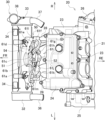
図5及び図6を参照して、ラジエータファンの排風の流れについて説明する。図5は本実施例のエンジン周辺の側面図である。図6は本実施例のエンジン周辺の上面図である。 The flow of exhaust air from the radiator fan will be described with reference to Figures 5 and 6. Figure 5 is a side view of the engine periphery of this embodiment. Figure 6 is a top view of the engine periphery of this embodiment.
図5及び図6に示すように、ラジエータ30には一対の上部ステー34及び単一の下部ステー35が設けられている。一対の上部ステー34が一対のフレームブラケット45(図1参照)を介して車体フレーム10(図1参照)に支持されており、下部ステー35がエンジンブラケット46を介してシリンダ22に支持されている。上部ステー34及びフレームブラケット45がゴムクッションを介して連結され、下部ステー35及びエンジンブラケット46がゴムクッションを介して連結されている。ゴムクッションによってラジエータ30が車体フレーム10及びエンジン20に浮動支持されている。
As shown in Figures 5 and 6, the
シリンダヘッド23の前面から下方に一対の排気管28が延びており、エンジン20の前方で一対の排気管28の上方にラジエータ30が位置している。ラジエータ30から排風が流れ易くなるように、ラジエータ30とエンジン20の前後間隔が広く確保されている。ラジエータ30の後面にラジエータファン50が取付られ、ラジエータ30、エンジン20、一対の排気管28に囲まれた空間にラジエータファン50が位置している。上面視にてラジエータファン50はラジエータ30の中央に位置しており、側面視にてラジエータファン50の上部がシリンダヘッド23よりも上方に位置している。
A pair of
ラジエータファン50には、プロペラ51の排風によるライダーに対する熱害を避けるためにファンシュラウド54が設けられている。上記したようにファンシュラウド54の後面にはフード61a-61mが形成されているため、ファンシュラウド54によって走行風やプロペラ51の排風が抜け難くなることがない。フード61a-61mから斜め下方及び側方に排風されるため、ファンシュラウド54から走行風やプロペラ51の排風が抜けても、エンジン20の後方のライダーに対する熱害が抑えられている。導風板等を配置する構成と比較しても部品点数が減ってコストが低減されている。
The
ラジエータファン50にはファンモータ52のように耐熱性が高くない部品が使用されている。このため、通常であればラジエータファン50と一対の排気管28に十分なクリアランスを確保するように車両レイアウトに制約が生じる。上記したように、フード61a、61bの排風口62がファンモータ52に向けられ、フード61f-61iの排風口62が一対の排気管28に向けられている。フード61a、61bからの排風によってファンモータ52が冷却され、フード61f-61iからの排風によって一対の排気管28が冷却される。よって、ラジエータファン50が一対の排気管28に近づけられて車両レイアウトの自由度が向上される。
The
一対の排気管28とラジエータ30の間にはモータ幅よりも幅広なファンシュラウド54の下部が介在しており、ファンシュラウド54の下部には排気管除けの一対の凹面64が形成されている。この一対の凹面64に一対の排気管28の湾曲部分が対向しており、一対の凹面64と一対の排気管28の湾曲部分の距離が縮められる。ファンシュラウド54の下部に一対の排気管28からの熱が遮られると共に、ファンシュラウド54の下部と一対の排気管28が壁になって地面から跳ね上げられた小石からラジエータファン50が保護される。プロペラ51とファンモータ52の間に小石が詰まり難くなってプロペラ51のロックが抑えられる。
Between the pair of
ファンシュラウド54にはプロペラ51の回転中心O(図2参照)よりも下側にフード61f-61kが配置されており、フード61f-61kがファンモータ52と一対の排気管28の間に位置付けられている。上記したように、ファンシュラウド54の後面からのフード61f-61kの膨出量とファンシュラウド54の後面からのファンモータ52の膨出量が略一致しており、フード61f-61kが一対の排気管28からファンモータ52に向かう熱気に対する遮熱板として機能する。フード61f-61kによって一対の排気管28からの熱が遮られてファンモータ52への熱害が抑えられている。
The
以上、本実施例によれば、プロペラ51がファンシュラウド54に後方から覆われているが、ファンシュラウド54には複数のフード61a-61mが形成されているため、走行風やプロペラ51の排風の抜け難くなることがない。また、フード61a-61mの排風口62が横方向から下方向までの範囲の何れかの方向に向けられているため、ラジエータコア31を通過した熱気がエンジン20の後方のライダーに向かい難くなる。よって、ライダーに対する熱害を抑えつつ、ラジエータファン50の冷却性能を維持することができる。
As described above, according to this embodiment, the
なお、本実施例では、エンジンとして2気筒エンジンを例示したが、エンジンの種類は特に限定されない。 In this embodiment, a two-cylinder engine is used as an example of the engine, but the type of engine is not particularly limited.
また、本実施例では、ファンシュラウドに複数のフードが開閉不能に設けられているが、ファンシュラウドには複数のフードが開閉可能に設けられていてもよい。この場合、複数のフードには戻しバネが設けられており、複数のフードに作用する風圧の大きさに応じて複数のフードが開閉される。プロペラが駆動する風圧では複数のフードが閉じられていて、プロペラ駆動の風圧以上である一定車速以上に達すると、走行風の風圧でフードが開かれる。走行風が無い中でプロペラが駆動してもフードが閉じられるのでライダーへの熱害が低減され、走行風の風圧でフードが開くことでラジエータをより冷却することができる。また、一定の走行風がある中でプロペラが駆動しても、走行風によってプロペラの排風熱が和らげられてライダーに熱を感じ難くさせることができる。 In this embodiment, the fan shroud is provided with multiple hoods that cannot be opened or closed, but the fan shroud may be provided with multiple hoods that can be opened or closed. In this case, the multiple hoods are provided with return springs, and the multiple hoods are opened or closed depending on the magnitude of the wind pressure acting on the multiple hoods. The multiple hoods are closed by the wind pressure driven by the propeller, and when the vehicle speed reaches a certain speed or higher that is equal to or higher than the wind pressure driven by the propeller, the hoods are opened by the wind pressure of the traveling wind. Even if the propeller is driven in the absence of traveling wind, the hoods are closed, reducing thermal damage to the rider, and the radiator can be cooled more by opening the hoods by the wind pressure of the traveling wind. Even if the propeller is driven in the presence of a certain amount of traveling wind, the propeller exhaust air heat is softened by the traveling wind, making it difficult for the rider to feel the heat.
また、本実施例では、ファンシュラウドの後面に複数のフードが形成されたが、ファンシュラウドの側面に複数のフードが形成されてもよい。 In addition, in this embodiment, multiple hoods are formed on the rear surface of the fan shroud, but multiple hoods may be formed on the side surfaces of the fan shroud.
また、本実施例では、鞍乗型車両の艤装品について特に説明していないが、艤装品にはファンモータに走行風や排風が向かうような導風形状が形成されていてもよい。 In addition, although this embodiment does not specifically describe the fittings of the saddle-type vehicle, the fittings may be formed with an air guide shape that directs the running wind and exhaust air toward the fan motor.
また、本実施例では、プロペラの回転中心よりも上側のフードの排風口がファンモータに向けられているが、これらのフードの排風口は横方向から下方向までの範囲で何れかの方向に向けられていればよく、ファンモータに向けられなくてもよい。 In addition, in this embodiment, the hood exhaust ports above the propeller's rotation center are directed toward the fan motor, but these hood exhaust ports may be directed in any direction between the side and the bottom, and do not have to be directed toward the fan motor.
また、本実施例では、プロペラの回転中心よりも下側のフードの排風口が排気管に向けられているが、これらのフードの排風口は横方向から下方向までの範囲で何れかの方向に向けられていればよく、排気管に向けられなくてもよい。 In addition, in this embodiment, the exhaust ports of the hoods below the center of rotation of the propeller are directed toward the exhaust pipe, but these hood exhaust ports may be directed in any direction between the side and the bottom, and do not have to be directed toward the exhaust pipe.
また、本実施例では、ファンシュラウドの上半部が後面視半円状に形成され、ファンシュラウドの下半部が後面視矩形状に形成されたが、ファンシュラウドの形状は特に限定されない。ファンシュラウドは少なくともプロペラを後方から覆うように形成されていればよい。 In addition, in this embodiment, the upper half of the fan shroud is formed in a semicircular shape when viewed from the rear, and the lower half of the fan shroud is formed in a rectangular shape when viewed from the rear, but the shape of the fan shroud is not particularly limited. It is sufficient that the fan shroud is formed so as to at least cover the propeller from the rear.
また、本実施例の複数のフードの排風口の向きは一例であり、複数のフードの排風口は横方向から下方向までの範囲で何れかの方向に向けられていればよい。 The orientation of the exhaust ports of the multiple hoods in this embodiment is merely an example, and the exhaust ports of the multiple hoods may be oriented in any direction within the range from sideways to downwards.
また、本実施例では、ファンシュラウドの後面からの複数のフードの膨出量が、ファンシュラウドの後面からのファンモータの膨出量と略一致しているが、複数のフードの膨出量は特に限定されない。既存の車両レイアウトを崩さないように、ファンシュラウドの後面からの複数のフードの膨出量が、ファンシュラウドの後面からのファンモータの膨出量以下に抑えられることが好ましい。 In addition, in this embodiment, the amount of bulging of the multiple hoods from the rear surface of the fan shroud is approximately the same as the amount of bulging of the fan motor from the rear surface of the fan shroud, but the amount of bulging of the multiple hoods is not particularly limited. In order not to disrupt the existing vehicle layout, it is preferable that the amount of bulging of the multiple hoods from the rear surface of the fan shroud be kept less than or equal to the amount of bulging of the fan motor from the rear surface of the fan shroud.
また、ラジエータファンは、図示の鞍乗型車両に限らず、他のタイプの鞍乗型車両に採用されてもよい。鞍乗型車両とは、ライダーがシートに跨った姿勢で乗車する車両全般に限定されず、ライダーがシートに跨らずに乗車する小型のスクータタイプの車両も含んでいる。 The radiator fan is not limited to the saddle-ride vehicle shown in the figure, and may be used in other types of saddle-ride vehicles. A saddle-ride vehicle is not limited to vehicles in general on which the rider sits astride the seat, but also includes small scooter-type vehicles on which the rider does not sit astride the seat.
以上の通り、本実施例のラジエータファン(50)は、エンジン(20)前方のラジエータ(30)に外気を導入するラジエータファンであって、ラジエータの後方に配置されたプロペラ(51)と、プロペラを回転駆動させるファンモータ(52)と、プロペラを後方から覆うファンシュラウド(54)と、を備え、ファンシュラウドには、横方向から下方向までの範囲で何れかの方向に排風口(62)を向けた複数のフード(61a-61m)が形成されている。この構成によれば、プロペラがファンシュラウドに後方から覆われているが、ファンシュラウドには複数のフードが形成されているため、走行風やプロペラの排風の抜け難くなることがない。また、フードの排風口が横方向から下方向までの範囲の何れかの方向に向けられているため、ラジエータコアを通過した熱気がエンジンの後方のライダーに向かい難くなる。よって、ライダーに対する熱害を抑えつつ、ラジエータファンの冷却性能を維持することができる。 As described above, the radiator fan (50) of this embodiment is a radiator fan that introduces outside air into the radiator (30) in front of the engine (20), and includes a propeller (51) disposed behind the radiator, a fan motor (52) that drives the propeller to rotate, and a fan shroud (54) that covers the propeller from the rear. The fan shroud is formed with multiple hoods (61a-61m) with exhaust ports (62) facing in any direction from the side to the bottom. With this configuration, the propeller is covered from the rear by the fan shroud, but since multiple hoods are formed on the fan shroud, it is not difficult for the running wind and the propeller exhaust air to escape. In addition, since the exhaust ports of the hoods are facing in any direction from the side to the bottom, the hot air that has passed through the radiator core is less likely to head toward the rider behind the engine. Therefore, it is possible to maintain the cooling performance of the radiator fan while suppressing heat damage to the rider.
本実施例のラジエータファンにおいて、複数のフードのうちプロペラの回転中心よりも上側のフードの排風口が、ファンモータに向けられている。この構成によれば、フードからファンモータに走行風又はプロペラの排風が吹き付けられ、ファンモータが冷却されて熱気によるファンモータの機能低下が防止される。熱害によるファンモータの車両レイアウトの制約が緩和されてラジエータファンを排気管等の熱源に近づけることができる。 In the radiator fan of this embodiment, the exhaust port of the hood that is above the center of rotation of the propeller is directed toward the fan motor. With this configuration, the hood blows the wind from the vehicle's running or the exhaust air from the propeller onto the fan motor, cooling the fan motor and preventing a decrease in the performance of the fan motor due to hot air. The constraints on the vehicle layout of the fan motor due to heat damage are alleviated, and the radiator fan can be moved closer to a heat source such as an exhaust pipe.
本実施例のラジエータファンにおいて、複数のフードのうちプロペラの回転中心よりも下側のフードの排風口が、エンジンから延びる排気管(28)に向けられている。この構成によれば、フードから排気管に走行風又はプロペラの排風が吹き付けられ、排気管が冷却されてファンモータに対する熱害が抑えられる。熱害によるファンモータの車両レイアウトの制約が緩和されてラジエータファンを排気管等の熱源に近づけることができる。 In the radiator fan of this embodiment, the exhaust port of the hood that is lower than the center of rotation of the propeller among the multiple hoods is directed toward the exhaust pipe (28) extending from the engine. With this configuration, the running wind or the propeller exhaust air is blown from the hood to the exhaust pipe, which cools the exhaust pipe and suppresses heat damage to the fan motor. The constraints on the vehicle layout of the fan motor due to heat damage are alleviated, and the radiator fan can be brought closer to a heat source such as the exhaust pipe.
本実施例のラジエータファンにおいて、ファンシュラウドの下部がエンジンから延びる排気管とラジエータの間に介在し、ファンシュラウドの下部には排気管を避ける凹面(64)が形成されている。この構成によれば、ファンシュラウドの下部によって排気管からの熱が遮られ、ラジエータファンに対する熱害が抑えられる。ファンシュラウドに凹面が形成されることで、ファンシュラウドと排気管の距離を縮められる。 In the radiator fan of this embodiment, the lower part of the fan shroud is interposed between the exhaust pipe extending from the engine and the radiator, and a concave surface (64) that avoids the exhaust pipe is formed on the lower part of the fan shroud. With this configuration, the lower part of the fan shroud blocks heat from the exhaust pipe, suppressing heat damage to the radiator fan. By forming a concave surface on the fan shroud, the distance between the fan shroud and the exhaust pipe can be shortened.
本実施例のラジエータファンにおいて、複数のフードの排風口からの排風方向がプロペラの回転方向と不一致である。この構成によれば、プロペラの駆動時に、フードの内面に排風が当ることで勢いが落ちて、ライダーに対する熱害を抑えることができる。 In the radiator fan of this embodiment, the direction of the exhaust air from the exhaust ports of the multiple hoods does not match the direction of rotation of the propeller. With this configuration, when the propeller is driven, the exhaust air hits the inner surface of the hood, reducing its momentum, thereby reducing heat damage to the rider.
本実施例のラジエータファンにおいて、複数のフードはファンシュラウドの後面から後方に膨出しており、ファンシュラウドの後面からの複数のフードの膨出量が、当該ファンシュラウドの後面からのファンモータの膨出量以下に抑えられている。この構成によれば、複数のフードがファンシュラウドの後面に形成されていても、既存の車両レイアウトが崩されることがない。 In the radiator fan of this embodiment, the multiple hoods bulge rearward from the rear surface of the fan shroud, and the amount by which the multiple hoods bulge from the rear surface of the fan shroud is kept below the amount by which the fan motor bulges from the rear surface of the fan shroud. With this configuration, even if multiple hoods are formed on the rear surface of the fan shroud, the existing vehicle layout is not disrupted.
本実施例のラジエータファンにおいて、複数のフードのうちプロペラの回転中心よりも下側のフードが、ファンモータとエンジンから延びる排気管との間に位置付けられている。この構成によれば、フードが遮熱板として機能することで、排気管によるファンモータへの熱害を抑えることができる。 In the radiator fan of this embodiment, of the multiple hoods, the hood below the center of rotation of the propeller is positioned between the fan motor and the exhaust pipe extending from the engine. With this configuration, the hood functions as a heat shield, thereby reducing thermal damage to the fan motor caused by the exhaust pipe.
なお、本実施例を説明したが、他の実施例として、上記実施例及び変形例を全体的又は部分的に組み合わせたものでもよい。 Although this embodiment has been described, other embodiments may be combinations of the above embodiments and variations in whole or in part.
また、本発明の技術は上記の実施例に限定されるものではなく、技術的思想の趣旨を逸脱しない範囲において様々に変更、置換、変形されてもよい。さらには、技術の進歩又は派生する別技術によって、技術的思想を別の仕方で実現することができれば、その方法を用いて実施されてもよい。したがって、特許請求の範囲は、技術的思想の範囲内に含まれ得る全ての実施態様をカバーしている。 Furthermore, the technology of the present invention is not limited to the above examples, and may be modified, substituted, or altered in various ways without departing from the spirit of the technical idea. Furthermore, if the technical idea can be realized in a different way due to technological advances or other derived technologies, it may be implemented using that method. Therefore, the claims cover all embodiments that may fall within the scope of the technical idea.
20 :エンジン
28 :排気管
30 :ラジエータ
50 :ラジエータファン
51 :プロペラ
52 :ファンモータ
54 :ファンシュラウド
61a-61m:フード
62 :排風口
64 :凹面
20: engine 28: exhaust pipe 30: radiator 50: radiator fan 51: propeller 52: fan motor 54:
Claims (6)
前記ラジエータの後方に配置されたプロペラと、
前記プロペラを回転駆動させるファンモータと、
前記プロペラを後方から覆うファンシュラウドと、を備え、
前記ファンシュラウドには、横方向から下方向までの範囲で何れかの方向に排風口を向けた複数のフードが形成され、
前記複数のフードのうち前記プロペラの回転中心よりも上側のフードの排風口が、前記ファンモータに向けられていることを特徴とするラジエータファン。 A radiator fan that introduces outside air into a radiator in front of the engine,
a propeller disposed rearward of the radiator;
A fan motor that drives and rotates the propeller;
a fan shroud covering the propeller from the rear,
The fan shroud is formed with a plurality of hoods each having an exhaust port facing in any direction within a range from the lateral direction to the downward direction ,
A radiator fan, characterized in that an exhaust port of a hood above a rotation center of the propeller among the plurality of hoods is directed toward the fan motor .
前記ラジエータの後方に配置されたプロペラと、
前記プロペラを回転駆動させるファンモータと、
前記プロペラを後方から覆うファンシュラウドと、を備え、
前記ファンシュラウドには、横方向から下方向までの範囲で何れかの方向に排風口を向けた複数のフードが形成され、
前記複数のフードのうち前記プロペラの回転中心よりも下側のフードの排風口が、前記エンジンから延びる排気管に向けられていることを特徴とするラジエータファン。 A radiator fan that introduces outside air into a radiator in front of the engine,
a propeller disposed rearward of the radiator;
A fan motor that drives and rotates the propeller;
a fan shroud covering the propeller from the rear,
The fan shroud is formed with a plurality of hoods each having an exhaust port facing in any direction within a range from the lateral direction to the downward direction ,
A radiator fan, characterized in that an exhaust port of one of the plurality of hoods that is below the center of rotation of the propeller is directed toward an exhaust pipe extending from the engine .
前記ラジエータの後方に配置されたプロペラと、
前記プロペラを回転駆動させるファンモータと、
前記プロペラを後方から覆うファンシュラウドと、を備え、
前記ファンシュラウドには、横方向から下方向までの範囲で何れかの方向に排風口を向けた複数のフードが形成され、
前記ファンシュラウドの下部が前記エンジンから延びる排気管と前記ラジエータの間に介在し、前記ファンシュラウドの下部には前記排気管を避ける凹面が形成されていることを特徴とするラジエータファン。 A radiator fan that introduces outside air into a radiator in front of the engine,
a propeller disposed rearward of the radiator;
A fan motor that drives and rotates the propeller;
a fan shroud covering the propeller from the rear,
The fan shroud is formed with a plurality of hoods each having an exhaust port facing in any direction within a range from the lateral direction to the downward direction ,
A radiator fan, characterized in that a lower portion of the fan shroud is interposed between an exhaust pipe extending from the engine and the radiator, and a concave surface is formed on the lower portion of the fan shroud to avoid the exhaust pipe .
前記ファンシュラウドの後面からの前記複数のフードの膨出量が、当該ファンシュラウドの後面からの前記ファンモータの膨出量以下に抑えられていることを特徴とする請求項1から請求項4のいずれか1項に記載のラジエータファン。 The plurality of hoods bulge rearward from a rear surface of the fan shroud,
5. The radiator fan according to claim 1, wherein the amount of projection of the plurality of hoods from the rear surface of the fan shroud is kept equal to or less than the amount of projection of the fan motor from the rear surface of the fan shroud.
Priority Applications (3)
| Application Number | Priority Date | Filing Date | Title |
|---|---|---|---|
| JP2021127685A JP7643246B2 (en) | 2021-08-03 | 2021-08-03 | Radiator fan |
| US17/858,711 US11788551B2 (en) | 2021-08-03 | 2022-07-06 | Radiator fan |
| DE102022118469.2A DE102022118469B4 (en) | 2021-08-03 | 2022-07-25 | COOLING FAN |
Applications Claiming Priority (1)
| Application Number | Priority Date | Filing Date | Title |
|---|---|---|---|
| JP2021127685A JP7643246B2 (en) | 2021-08-03 | 2021-08-03 | Radiator fan |
Publications (2)
| Publication Number | Publication Date |
|---|---|
| JP2023022678A JP2023022678A (en) | 2023-02-15 |
| JP7643246B2 true JP7643246B2 (en) | 2025-03-11 |
Family
ID=84975224
Family Applications (1)
| Application Number | Title | Priority Date | Filing Date |
|---|---|---|---|
| JP2021127685A Active JP7643246B2 (en) | 2021-08-03 | 2021-08-03 | Radiator fan |
Country Status (3)
| Country | Link |
|---|---|
| US (1) | US11788551B2 (en) |
| JP (1) | JP7643246B2 (en) |
| DE (1) | DE102022118469B4 (en) |
Citations (3)
| Publication number | Priority date | Publication date | Assignee | Title |
|---|---|---|---|---|
| JP2019038290A (en) | 2017-08-22 | 2019-03-14 | 川崎重工業株式会社 | Saddle-riding type vehicle and radiator air guiding device |
| WO2020197857A2 (en) | 2019-03-22 | 2020-10-01 | Indian Motorcycle International, LLC | Two-wheeled vehicle |
| JP2021160605A (en) | 2020-03-31 | 2021-10-11 | 本田技研工業株式会社 | Saddle-riding type vehicle |
Family Cites Families (5)
| Publication number | Priority date | Publication date | Assignee | Title |
|---|---|---|---|---|
| JPS5810656Y2 (en) * | 1977-04-28 | 1983-02-26 | 川崎重工業株式会社 | Liquid-cooled engine cooling air exhaust device for motorcycles |
| JPS5829907B2 (en) | 1977-06-20 | 1983-06-25 | 日本電信電話株式会社 | Carrier extraction method |
| JP4390166B2 (en) * | 1999-12-17 | 2009-12-24 | 本田技研工業株式会社 | Radiator arrangement structure of motorcycle |
| JP5829907B2 (en) | 2011-12-28 | 2015-12-09 | 川崎重工業株式会社 | Saddle riding vehicle |
| JP6689798B2 (en) * | 2017-08-30 | 2020-04-28 | 本田技研工業株式会社 | Saddle type vehicle |
-
2021
- 2021-08-03 JP JP2021127685A patent/JP7643246B2/en active Active
-
2022
- 2022-07-06 US US17/858,711 patent/US11788551B2/en active Active
- 2022-07-25 DE DE102022118469.2A patent/DE102022118469B4/en active Active
Patent Citations (3)
| Publication number | Priority date | Publication date | Assignee | Title |
|---|---|---|---|---|
| JP2019038290A (en) | 2017-08-22 | 2019-03-14 | 川崎重工業株式会社 | Saddle-riding type vehicle and radiator air guiding device |
| WO2020197857A2 (en) | 2019-03-22 | 2020-10-01 | Indian Motorcycle International, LLC | Two-wheeled vehicle |
| JP2021160605A (en) | 2020-03-31 | 2021-10-11 | 本田技研工業株式会社 | Saddle-riding type vehicle |
Also Published As
| Publication number | Publication date |
|---|---|
| US20230040841A1 (en) | 2023-02-09 |
| JP2023022678A (en) | 2023-02-15 |
| DE102022118469A1 (en) | 2023-02-09 |
| US11788551B2 (en) | 2023-10-17 |
| DE102022118469B4 (en) | 2025-12-24 |
Similar Documents
| Publication | Publication Date | Title |
|---|---|---|
| JP3059280B2 (en) | Radiator arrangement structure for motorcycle | |
| JP5829907B2 (en) | Saddle riding vehicle | |
| JP6845766B2 (en) | Saddle-type vehicle and radiator wind guide | |
| EP3450293B1 (en) | Saddle riding vehicle | |
| JP7643246B2 (en) | Radiator fan | |
| EP2631447B1 (en) | Saddle-ride type vehicle | |
| JP7517026B2 (en) | Front fender | |
| US9624819B2 (en) | Radiator arrangement structure for saddle-ride type vehicles | |
| JP7282652B2 (en) | vehicle | |
| CN109715912B (en) | Cooling structure of saddle type internal combustion engine for vehicle | |
| JP7198628B2 (en) | straddle-type vehicle | |
| JP7787220B2 (en) | Saddle-type vehicle | |
| JP7815963B2 (en) | Guard Structure | |
| JP7578053B2 (en) | Radiator fan | |
| JP7661386B2 (en) | Saddle-type vehicle | |
| JP2000238687A (en) | Motorcycle cooling system | |
| EP4368484A1 (en) | Straddled vehicle | |
| EP4368485A1 (en) | Straddled vehicle | |
| JP6147534B2 (en) | Saddle riding vehicle | |
| JP4579127B2 (en) | Engine cooling structure for saddle riding type vehicles | |
| JP2024104470A (en) | Saddle-type vehicle | |
| JP2023158882A (en) | guard structure | |
| JP6620797B2 (en) | Engine room shielding structure | |
| JP2025073194A (en) | engine | |
| JP2025008643A (en) | Radiator unit for saddle-ride vehicles or ATVs |
Legal Events
| Date | Code | Title | Description |
|---|---|---|---|
| A621 | Written request for application examination |
Free format text: JAPANESE INTERMEDIATE CODE: A621 Effective date: 20240416 |
|
| A977 | Report on retrieval |
Free format text: JAPANESE INTERMEDIATE CODE: A971007 Effective date: 20241219 |
|
| A131 | Notification of reasons for refusal |
Free format text: JAPANESE INTERMEDIATE CODE: A131 Effective date: 20250107 |
|
| A521 | Request for written amendment filed |
Free format text: JAPANESE INTERMEDIATE CODE: A523 Effective date: 20250115 |
|
| TRDD | Decision of grant or rejection written | ||
| A01 | Written decision to grant a patent or to grant a registration (utility model) |
Free format text: JAPANESE INTERMEDIATE CODE: A01 Effective date: 20250128 |
|
| A61 | First payment of annual fees (during grant procedure) |
Free format text: JAPANESE INTERMEDIATE CODE: A61 Effective date: 20250210 |
|
| R150 | Certificate of patent or registration of utility model |
Ref document number: 7643246 Country of ref document: JP Free format text: JAPANESE INTERMEDIATE CODE: R150 |