JP7641663B1 - palette - Google Patents

palette Download PDF

Info

Publication number
JP7641663B1
JP7641663B1 JP2023219034A JP2023219034A JP7641663B1 JP 7641663 B1 JP7641663 B1 JP 7641663B1 JP 2023219034 A JP2023219034 A JP 2023219034A JP 2023219034 A JP2023219034 A JP 2023219034A JP 7641663 B1 JP7641663 B1 JP 7641663B1
Authority
JP
Japan
Prior art keywords
wall member
lock bar
bottom plate
wall
support
Prior art date
Legal status (The legal status is an assumption and is not a legal conclusion. Google has not performed a legal analysis and makes no representation as to the accuracy of the status listed.)
Active
Application number
JP2023219034A
Other languages
Japanese (ja)
Other versions
JP2025101928A (en
Inventor
尚記 西田
Original Assignee
日本物流機器株式会社
Priority date (The priority date is an assumption and is not a legal conclusion. Google has not performed a legal analysis and makes no representation as to the accuracy of the date listed.)
Filing date
Publication date
Application filed by 日本物流機器株式会社 filed Critical 日本物流機器株式会社
Priority to JP2023219034A priority Critical patent/JP7641663B1/en
Application granted granted Critical
Publication of JP7641663B1 publication Critical patent/JP7641663B1/en
Publication of JP2025101928A publication Critical patent/JP2025101928A/en
Active legal-status Critical Current
Anticipated expiration legal-status Critical

Links

Images

Landscapes

  • Pallets (AREA)

Abstract

Figure 0007641663000001

【課題】ロックの実行および解除を容易に行う。
【解決手段】パレット100は、底板部材1と、底板部材における左右の少なくとも一方の端部に回動可能に設けられた第1壁部材2と、第1壁部材を底板部材に起立状態でロックするための第1ロック機構4とを備える。第1壁部材は、その前後の端部に設けられた第1支柱21を有し、底板部材は、前後の第1支柱が回動可能に接続される前後の支柱受け6を有する。第1ロック機構は、前後の第1支柱を掛け渡すと共に前後の第1支柱に昇降可能に設けられた第1ロックバーと、前後の支柱受けに設けられ、第1ロックバーが上下方向に挿抜可能な第1スロットとを有する。
【選択図】図1

Figure 0007641663000001

To easily execute and release a lock.
[Solution] A pallet 100 comprises a bottom plate member 1, a first wall member 2 rotatably provided on at least one of the left and right ends of the bottom plate member, and a first locking mechanism 4 for locking the first wall member in an upright state on the bottom plate member. The first wall member has first support posts 21 provided on front and rear ends thereof, and the bottom plate member has front and rear support post holders 6 to which the front and rear first support posts are rotatably connected. The first locking mechanism has a first locking bar that spans the front and rear first support posts and is provided on the front and rear first support posts so as to be able to rise and fall, and first slots that are provided on the front and rear support post holders and into which the first locking bar can be inserted and removed in the vertical direction.
[Selected Figure] Figure 1

Description

本開示はパレットに関する。 This disclosure relates to pallets.

工場等の施設において荷物をフォークリフト等で搬送するためにパレットが用いられている。パレットは一般的に、上方が開放された直方体形状とされ、荷物を載せる底板部材と、底板部材における前後左右の端部に回動可能に設けられた4枚の壁部材とを備える。荷物の搬送時にはそれら壁部材が起立状態でロックされる。荷物を搬送しない保管時等には、ロックが解除され、それら壁部材が転倒状態で底板部材に載せられる。これによりパレットは折り畳まれる。保管スペース縮小のため、折り畳まれた複数のパレットが上下方向に段積みされることがある。 Pallets are used in factories and other facilities to transport cargo using forklifts and the like. Pallets are generally rectangular parallelepipeds with an open top, and comprise a bottom plate member on which cargo is placed, and four wall members rotatably attached to the front, back, left and right ends of the bottom plate member. When cargo is being transported, the wall members are locked in an upright position. When cargo is not being transported, such as during storage, the locks are released and the wall members are placed in an upside-down position on the bottom plate member. This folds the pallet. To reduce storage space, multiple folded pallets may be stacked vertically.

実開平7-28829号公報Japanese Utility Model Application Publication No. 7-28829

ところで、第1従来例のパレットでは、ロックの実行および解除を行うとき、壁部材を持ち上げてその支柱を支柱受けに挿抜する必要がある。そのため、力が弱い女性等の作業者が行い難いという問題がある。 However, with the first conventional pallet, when locking or unlocking, it is necessary to lift the wall member and insert or remove the support pole into the support pole receiver. This creates a problem in that it is difficult for workers with weak strength, such as women, to perform the operation.

第2従来例のパレットでは、ロックの実行および解除を行うとき、壁部材の両端部にあるピンを穴に挿抜する必要がある。そのため、壁部材の両端部に作業者がいちいち移動しなければならず、面倒である。 In the second conventional pallet example, when locking and unlocking, it is necessary to insert and remove pins at both ends of the wall member into holes. This requires the worker to move to both ends of the wall member each time, which is cumbersome.

このように従来のパレットでは、ロックの実行および解除が煩雑であるという問題がある。 As such, conventional pallets have the problem that locking and unlocking them is cumbersome.

そこで本開示は、かかる事情に鑑みて創案され、その目的は、ロックの実行および解除を容易に行うことができるパレットを提供することにある。 The present disclosure was conceived in light of these circumstances, and its purpose is to provide a pallet that can be easily locked and unlocked.

本開示の一の態様によれば、
底板部材と、
前記底板部材における左右の少なくとも一方の端部に回動可能に設けられた第1壁部材と、
前記第1壁部材を前記底板部材に起立状態でロックするための第1ロック機構と、
を備え、
前記第1壁部材は、その前後の端部に設けられた第1支柱を有し、
前記底板部材は、前後の前記第1支柱が回動可能に接続される前後の支柱受けを有し、
前記第1ロック機構は、
前後の前記第1支柱を掛け渡すと共に前後の前記第1支柱に昇降可能に設けられた第1ロックバーと、
前後の前記支柱受けに設けられ、前記第1ロックバーが上下方向に挿抜可能な第1スロットと、
を有する
ことを特徴とするパレットが提供される。
According to one aspect of the present disclosure,
A bottom plate member;
a first wall member rotatably provided on at least one of the left and right ends of the bottom plate member;
a first locking mechanism for locking the first wall member to the bottom plate member in an upright state;
Equipped with
The first wall member has first pillars provided at front and rear ends thereof,
the bottom plate member has front and rear support columns to which the front and rear first support columns are rotatably connected,
The first locking mechanism includes:
A first lock bar that spans the front and rear first pillars and is provided on the front and rear first pillars so as to be movable up and down;
a first slot provided in the front and rear support columns, into which the first lock bar can be inserted and removed in the up-down direction;
A pallet is provided, comprising:

好ましくは、前記第1ロック機構は、前後の前記支柱受けに設けられ前記第1壁部材の起立時に前記第1ロックバーを前記第1スロットに向かって案内する第1カム面を有する。 Preferably, the first locking mechanism has a first cam surface provided on the front and rear support columns that guides the first locking bar toward the first slot when the first wall member is raised.

好ましくは、前記第1カム面は、アール面または直線状傾斜面によって形成されている。 Preferably, the first cam surface is formed by a curved surface or a linearly inclined surface.

好ましくは、前記パレットは、
前記底板部材における左右の端部に回動可能に設けられた前記第1壁部材と、
前記底板部材における前後の少なくとも一方の端部に回動可能に設けられた第2壁部材と、
前記第2壁部材を左右の前記第1壁部材に起立状態でロックするための第2ロック機構と、
を備え、
前記第2壁部材は、その左右の端部に設けられた第2支柱を有し、
前記第2ロック機構は、
左右の前記第2支柱を掛け渡すと共に左右の前記第2支柱に昇降可能に設けられた第2ロックバーと、
左右の前記第1壁部材における前後の少なくとも一方の前記第1支柱に設けられ、前記第2ロックバーが上下方向に挿抜可能な第2スロットと、
を有する。
Preferably, the pallet comprises:
the first wall member rotatably provided on the left and right ends of the bottom plate member;
a second wall member rotatably provided on at least one of the front and rear ends of the bottom plate member;
a second locking mechanism for locking the second wall member in an upright state relative to the left and right first wall members;
Equipped with
The second wall member has second support pillars provided at left and right ends thereof,
The second locking mechanism is
A second lock bar that spans the left and right second support columns and is provided on the left and right second support columns so as to be movable up and down;
a second slot provided in at least one of the first posts at the front and rear of the first wall members, into which the second lock bar can be inserted and removed in the up-down direction;
has.

好ましくは、前記第2ロック機構は、左右の前記第1壁部材における前後の少なくとも一方の前記第1支柱に設けられ前記第2壁部材の起立時に前記第2ロックバーを前記第2スロットに向かって案内する第2カム面を有する。 Preferably, the second locking mechanism has a second cam surface provided on at least one of the first pillars at the front or rear of the left or right first wall member, which guides the second locking bar toward the second slot when the second wall member is erected.

好ましくは、前記第2カム面は、アール面または直線状傾斜面によって形成されている。 Preferably, the second cam surface is formed by a curved surface or a linearly inclined surface.

好ましくは、前記第2壁部材は、互いに回動可能に接続された上側第2壁部材および下側第2壁部材を有し、
前記第2ロック機構は、前記上側第2壁部材および前記下側第2壁部材に個別に設けられる。
Preferably, the second wall member includes an upper second wall member and a lower second wall member pivotally connected to each other,
The second locking mechanism is provided individually on the upper second wall member and the lower second wall member.

本開示によれば、ロックの実行および解除を容易に行うことができる。 This disclosure makes it easy to lock and unlock.

本実施形態に係るパレットの全体を示す前面図である。FIG. 2 is a front view showing the entire pallet according to the present embodiment. 本実施形態に係るパレットの全体を示す左側面図である。FIG. 2 is a left side view showing the entire pallet according to the embodiment. 底板部材を示す上面図である。FIG. 底板部材を示す前面図である。FIG. 底板部材を示す左側面図である。FIG. 支柱受けを示し、(A)は前面図、(B)は上面図、(C)は右側面図、(D)は左側面図である。1A is a front view of the support column receiver, FIG. 1B is a top view, FIG. 1C is a right side view, and FIG. 第1壁部材を示し、(A)は前面図、(B)は左側面図である。4A and 4B show a first wall member, in which FIG. 4A is a front view and FIG. (A)および(B)は、それぞれ、図7(A)のVIIIA-VIIIA断面およびVIIIB-VIIIB断面から見たときの右側および左側の第1支柱を部分的に示す図である。7A and 7B are diagrams partially showing the right and left first pillars as viewed from the VIIIA-VIIIA cross section and the VIIIB-VIIIB cross section of FIG. 7A, respectively. 第1ロックバーを示し、(A)は前面図、(B)は右側面図、(C)は左側面図である。1A is a front view of a first lock bar, FIG. 1B is a right side view, and FIG. 1C is a left side view. 上部ブラケットおよび下部ブラケットを示し、(1A)は上部ブラケットの前面図、(1B)は上部ブラケットの上面図、(2A)は下部ブラケットの前面図、(2B)は下部ブラケットの上面図である。1A shows an upper bracket and a lower bracket, where (1A) is a front view of the upper bracket, (1B) is a top view of the upper bracket, (2A) is a front view of the lower bracket, and (2B) is a top view of the lower bracket. 第2壁部材を示し、(A)は前面図、(B)は左側面図である。4A and 4B show a second wall member, in which FIG. 4A is a front view and FIG. 上側第2壁部材と第2ロックバーの組み合わせを示し、(A)は前面図、(B)は左側面図である。13A and 13B show a combination of an upper second wall member and a second lock bar, in which FIG. 上側第2壁部材を示し、(A)は前面図、(B)は左側面図である。4A and 4B show an upper second wall member, in which FIG. 4A is a front view and FIG. 上側第2壁部材を示し、図13のXIV-XIV断面図である。14 is a cross-sectional view of the upper second wall member taken along line XIV-XIV of FIG. 13. 第2ロックバーを示す前面図である。FIG. 13 is a front view showing the second lock bar. 第2ロックバーを示し、(A)は部分前面図、(B)は左側面図である。13A and 13B show a second lock bar, in which FIG. 底板部材のブラケットと回動シャフトの係合部との係合状態を示す断面図であり、図3のXVII-XVII断面相当図である。10 is a cross-sectional view showing an engagement state between a bracket of the bottom plate member and an engagement portion of the rotating shaft, and corresponds to a cross-sectional view taken along the line XVII-XVII in FIG. 3. 第2壁部材の折り畳み時の様子を模式的に示す概略図である。11 is a schematic diagram showing a state in which the second wall member is folded. FIG. 第1壁部材の折り畳み時の様子を模式的に示す概略図である。11 is a schematic diagram showing a state in which the first wall member is folded; FIG. 第1壁部材、第1ロックバーおよび底板部材の取付状態を透過的に示し、図6(C)相当図である。7 is a perspective view showing the attachment state of the first wall member, the first lock bar, and the bottom plate member, and corresponds to FIG. 6(C). FIG. 第2壁部材の起立時に第2ロックバーが第2スロットに向かって案内される様子を示す概略図である。13 is a schematic view showing a state in which the second lock bar is guided toward the second slot when the second wall member is erected. FIG. 図1のXXII-XXII断面図である。This is a cross-sectional view taken along line XXII-XXII of FIG. 図1のXXIII-XXIII断面図である。This is a cross-sectional view taken along line XXIII-XXIII of Figure 1.

以下、添付図面を参照して本開示の実施形態を説明する。なお本開示は以下の実施形態に限定されない点に留意されたい。 Embodiments of the present disclosure will be described below with reference to the accompanying drawings. Please note that the present disclosure is not limited to the following embodiments.

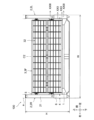
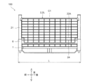
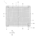
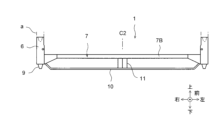
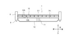
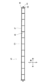
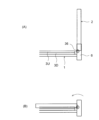
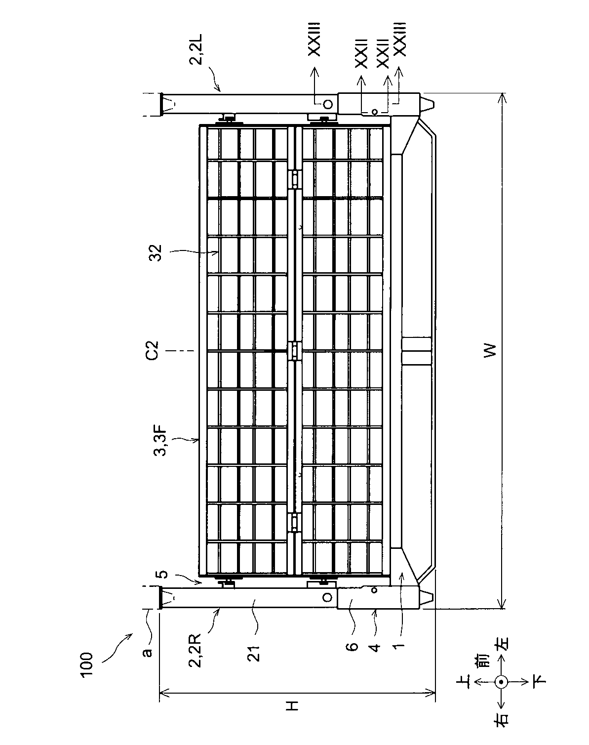
図1および図2は、本実施形態に係るパレットの全体を示す前面図および左側面図である。また図3は、パレットの底板部材のみを示す上面図である。便宜上、前後左右上下の各方向を図示の通り定める。 Figures 1 and 2 are a front view and a left side view showing the entire pallet according to this embodiment. Also, Figure 3 is a top view showing only the bottom plate member of the pallet. For convenience, the front-rear, left-right, top-bottom directions are defined as shown in the figures.

パレット100は概ね、上方が開放された直方体形状(立方体形状を含む)に形成され、前後方向の長さLと、左右方向の幅Wと、上下方向の高さHとを有する。図3には、前後長Lの中心である前後中心C1と、左右幅Wの中心である左右中心C2とを示す。パレット100は、前後中心C1を境に前後対称に形成され、左右中心C2を境に左右対称に形成されている。前後中心C1と左右中心C2の交点をパレット中心Oとする。 Pallet 100 is generally formed in a rectangular parallelepiped shape (including a cube shape) that is open at the top, and has a length L in the front-to-rear direction, a width W in the left-to-right direction, and a height H in the up-down direction. Figure 3 shows a front-to-rear center C1, which is the center of the front-to-rear length L, and a left-to-right center C2, which is the center of the left-to-right width W. Pallet 100 is formed symmetrically in the front-to-rear direction with respect to the front-to-rear center C1, and symmetrically with respect to the left-to-right center C2. The intersection of front-to-rear center C1 and left-to-right center C2 is the pallet center O.

パレット100は金属製、具体的には鉄製である。但し、パレット100の材質は任意であり、必要に応じて樹脂等の金属以外の材料を少なくとも一部に用いてもよい。 The pallet 100 is made of metal, specifically iron. However, the material of the pallet 100 is arbitrary, and materials other than metal, such as resin, may be used at least in part, if necessary.

パレット100は、荷物が載せられる底板部材1と、底板部材1における左右の端部に回動可能に設けられた第1壁部材2と、底板部材1における前後の端部に回動可能に設けられた第2壁部材3とを備える。これら第1壁部材2および第2壁部材3は、荷物の搬送時に図示の如く起立状態とされ、底板部材1に載せられた荷物が搬送中にこぼれ落ちるのを防止する。 The pallet 100 comprises a bottom plate member 1 on which cargo is placed, a first wall member 2 rotatably attached to the left and right ends of the bottom plate member 1, and a second wall member 3 rotatably attached to the front and rear ends of the bottom plate member 1. The first wall member 2 and the second wall member 3 are in an upright position as shown when cargo is being transported, preventing cargo placed on the bottom plate member 1 from falling off during transport.

第1壁部材2には、底板部材1の左端部に設けられた左壁部材2Lと、底板部材1の右端部に設けられた右壁部材2Rとがある。以下、総称としての第1壁部材2を主に用いる。 The first wall member 2 includes a left wall member 2L provided at the left end of the bottom plate member 1, and a right wall member 2R provided at the right end of the bottom plate member 1. Hereinafter, the general term "first wall member 2" will be used.

同様に、第2壁部材3には、底板部材1の前端部に設けられた前壁部材3Fと、底板部材1の後端部に設けられた後壁部材(図示せず)とがある。以下、総称としての第2壁部材3を主に用いる。 Similarly, the second wall member 3 includes a front wall member 3F provided at the front end of the bottom plate member 1, and a rear wall member (not shown) provided at the rear end of the bottom plate member 1. Hereinafter, the general term "second wall member 3" will be mainly used.

またパレット100は、第1壁部材2を底板部材1にロックするための第1ロック機構4と、第2壁部材3を第1壁部材2にロックするための第2ロック機構5とを備える。これらロック機構4,5の詳細については後述する。 The pallet 100 also includes a first locking mechanism 4 for locking the first wall member 2 to the bottom plate member 1, and a second locking mechanism 5 for locking the second wall member 3 to the first wall member 2. Details of these locking mechanisms 4 and 5 will be described later.

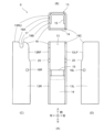
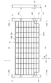
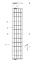
まず、図3~図5を用いて底板部材1を説明する。図4および図5は、底板部材1を示す前面図および左側面図である。 First, the bottom plate member 1 will be described using Figures 3 to 5. Figures 4 and 5 are a front view and a left side view showing the bottom plate member 1.

底板部材1は、その前後左右の四隅の位置に起立して配置された支柱受け6と、これら支柱受け6を連結する長方形枠状の底板フレーム7と、底板フレーム7の枠内に敷設された底板材8とを備える。 The bottom plate member 1 comprises support column holders 6 arranged upright at the four corners of the front, back, left and right sides, a rectangular bottom plate frame 7 that connects the support column holders 6, and a bottom plate material 8 laid within the frame of the bottom plate frame 7.

支柱受け6は上下方向に延びる角管状に形成される。底板フレーム7は、前後方向に延びて前後の支柱受け6に接続固定される左右のサイドメンバ7Aと、左右方向に延びて左右の支柱受け6に接続固定される前後のクロスメンバ7Bとを有する。これらサイドメンバ7Aとクロスメンバ7Bは角パイプにより形成される。 The pillar supports 6 are formed in the shape of square tubes extending in the vertical direction. The bottom plate frame 7 has left and right side members 7A that extend in the front-rear direction and are connected and fixed to the front and rear pillar supports 6, and front and rear cross members 7B that extend in the left-right direction and are connected and fixed to the left and right pillar supports 6. These side members 7A and cross members 7B are formed from square pipes.

底板材8は、本実施形態では金属ネットにより形成されている。底板フレーム7は、その枠内に格子状に設けられた底板材受け(図示せず)を有する。底板材受けに底板材8が載せられ、底板材8が底板材受けおよび底板フレーム7に溶接等により固定される。底板材8の上に荷物が載せられる。なお、底板材8は金属板により形成されてもよい。 In this embodiment, the bottom plate material 8 is formed of a metal net. The bottom plate frame 7 has a bottom plate material receiver (not shown) arranged in a lattice pattern within its frame. The bottom plate material 8 is placed on the bottom plate material receiver, and the bottom plate material 8 is fixed to the bottom plate material receiver and the bottom plate frame 7 by welding or the like. Luggage is placed on the bottom plate material 8. The bottom plate material 8 may also be formed of a metal plate.

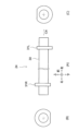
支柱受け6の下端部にテーパ状の差し込み部9が設けられる。図1および図4に仮想線aで示すように、この差し込み部9は、パレット100の段積み時に別のパレット100の支柱受け6、または第1支柱21(後述)の上端部に差し込まれる。 A tapered insertion portion 9 is provided at the lower end of the support post 6. As shown by the imaginary line a in Figures 1 and 4, this insertion portion 9 is inserted into the support post 6 of another pallet 100 or into the upper end of the first support 21 (described below) when the pallets 100 are stacked.

底板フレーム7の下方に、これに沿ってスキー板の如き接地板10が配置されている。接地板10は、サイドメンバ7Aおよびクロスメンバ7Bの真下にこれらに沿って設けられる。接地板10の両端部は支柱受け6に溶接等により固定される。接地板10の中間部は、上下方向に延びる脚材11を介して底板フレーム7に連結される。脚材11は接地板10と底板フレーム7に溶接等により固定される。 A ski-like ground plate 10 is arranged below and along the bottom plate frame 7. The ground plate 10 is provided directly below and along the side members 7A and cross members 7B. Both ends of the ground plate 10 are fixed to the support column 6 by welding or the like. The middle part of the ground plate 10 is connected to the bottom plate frame 7 via leg members 11 that extend in the vertical direction. The leg members 11 are fixed to the ground plate 10 and the bottom plate frame 7 by welding or the like.

パレット100が地面に置かれたとき、差し込み部9は接地せず、接地板10が接地する。脚材11により仕切られた、接地板10と底板フレーム7の間の2つのスペースに、フォークリフトの2本のフォークがそれぞれ挿入される。 When the pallet 100 is placed on the ground, the insertion portion 9 does not touch the ground, but the ground plate 10 does. The two forks of a forklift are inserted into the two spaces between the ground plate 10 and the bottom plate frame 7, which are separated by the legs 11.

底板部材1は、その左右の端部に設けられた底壁部材12を有する。底壁部材12は、底板フレーム7上に起立状態で固定され、底板材8に載せられた荷物が滑り落ちるのを防止する。底壁部材12は前後方向に延び、その両端部が支柱受け6に溶接等により固定される。底壁部材12は、上下一対の横材12Aを複数の縦材12Bで連結してなるはしご状金属柵の形態を有する。底壁部材12の高さは、支柱受け6の高さより低くされる。 The bottom plate member 1 has bottom wall members 12 provided at its left and right ends. The bottom wall member 12 is fixed in an upright state on the bottom plate frame 7 and prevents luggage placed on the bottom plate member 8 from sliding off. The bottom wall member 12 extends in the front-to-rear direction and both ends are fixed to the support column 6 by welding or the like. The bottom wall member 12 has the form of a ladder-shaped metal fence consisting of a pair of upper and lower horizontal members 12A connected by multiple vertical members 12B. The height of the bottom wall member 12 is made lower than the height of the support column 6.

図6は、差し込み部9を省略した支柱受け6を単体で示す。支柱受け6はその取付位置によって向きが異なる。そこで図6(A)を、前方から見たときの前面図とし、これを基準として前後左右上下の各方向を図6(A)に示す通りに定める。図6(A)において、紙面厚さ方向手前側が前、紙面厚さ方向奥側が後、紙面に向かって右側が左、左側が右、上側が上、下側が下である。よって図6において(B)は上面図、(C)は右側面図、(D)は左側面図である。 Figure 6 shows the support post holder 6 alone, with the insertion portion 9 omitted. The orientation of the support post holder 6 differs depending on its installation position. Therefore, Figure 6(A) is a front view as seen from the front, and based on this, the front, back, left, right, top and bottom directions are defined as shown in Figure 6(A). In Figure 6(A), the front side in the thickness direction of the paper is the front, the back side in the thickness direction of the paper is the back, the right side as viewed from the paper is the left, the left side is the right, the top is the top, and the bottom is the bottom. Therefore, in Figure 6, (B) is a top view, (C) is a right side view, and (D) is a left side view.

支柱受け6は、上下方向に延びる断面四角形(略正方形)の角管状である。支柱受け6は、上面視コ字状の支柱受け本体13と、支柱受け本体13の前面開口部の下半部を閉止する閉止板14と、支柱受け本体13の内面の高さ方向略中間部に取り付けられた上面視コ字状の支柱載置金具15とを備える。これら支柱受け本体13、閉止板14および支柱載置金具15は溶接等により一体に組み立てられる。 The support post holder 6 is a rectangular tube extending vertically and having a rectangular (approximately square) cross section. The support post holder 6 comprises a support post holder main body 13 that is U-shaped when viewed from above, a closing plate 14 that closes the lower half of the front opening of the support post holder main body 13, and a support post mounting bracket 15 that is U-shaped when viewed from above and attached to the inner surface of the support post holder main body 13 at approximately the middle in the height direction. The support post holder main body 13, the closing plate 14, and the support post mounting bracket 15 are assembled together by welding or the like.

閉止板14は、支柱受け本体13の左右の前端部に挟まれて固定される。支柱載置金具15は、支柱受け本体13よりも短い高さ寸法を有し、支柱受け本体13の内面に重ね合わされて固定される。支柱載置金具15は、第1支柱21(後述、図1参照)が起立されたとき第1支柱21を載置させ、第1支柱21を下から支えるものである。閉止板14は、支柱載置金具15の略中間高さ位置から下方の領域において、支柱受け本体13の前面開口部を閉止する。 The closure plate 14 is sandwiched and fixed between the left and right front ends of the support support body 13. The support support mounting bracket 15 has a height dimension shorter than the support support body 13 and is overlapped and fixed to the inner surface of the support support body 13. The support support mounting bracket 15 supports the first support 21 (described later, see Figure 1) when the first support 21 is erected, and supports the first support 21 from below. The closure plate 14 closes the front opening of the support support body 13 in an area below the approximately mid-height position of the support support mounting bracket 15.

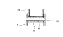
支柱受け本体13は、その左壁部13Lと右壁部13Rを同軸で貫通する貫通穴16L,16Rと、その右壁部13Rの上端面部13RUに形成された第1スロット17とを有する。詳しくは後述するが、貫通穴16L,16Rは、第1壁部材2の第1支柱21を回動可能に支持する回動シャフト26(図22参照)が挿通される穴である。第1スロット17は、前述の第1ロック機構4における第1ロックバー24(図7参照)が挿抜されるスロットすなわち溝であり、上下方向に延びると共に上端が開放されている。 The support support body 13 has through holes 16L, 16R that pass coaxially through the left wall portion 13L and the right wall portion 13R, and a first slot 17 formed in the upper end surface portion 13RU of the right wall portion 13R. As will be described in detail later, the through holes 16L, 16R are holes through which a pivot shaft 26 (see FIG. 22) that rotatably supports the first support 21 of the first wall member 2 is inserted. The first slot 17 is a slot, or groove, through which the first lock bar 24 (see FIG. 7) of the first lock mechanism 4 described above is inserted and removed, and extends in the vertical direction with an open upper end.

貫通穴16L,16Rは、左壁部13Lと右壁部13Rの前端部に設けられ、支柱載置金具15の上端面と略同一の高さ位置に設けられる。第1スロット17は、右壁部13Rの上端面部13RUにおける前後方向の略中心部に設けられる。 The through holes 16L, 16R are provided at the front ends of the left wall portion 13L and the right wall portion 13R, and are provided at approximately the same height as the upper end surface of the support mounting bracket 15. The first slot 17 is provided at approximately the center in the front-to-rear direction of the upper end surface portion 13RU of the right wall portion 13R.

また支柱受け本体13は、その右壁部13Rにおける上端面部13RUと前面部13RFとの交差部に設けられた第1カム面18を有する。第1カム面18は、その交差部を所定の曲率半径でアール状に切り欠いてなるアール面によって形成されている。詳しくは後述するが、第1カム面18は、第1壁部材2の起立時に第1ロックバー24を第1スロット17に向かって案内するカム面である。 The support pillar receiving body 13 also has a first cam surface 18 provided at the intersection of the upper end surface portion 13RU and the front surface portion 13RF on the right wall portion 13R. The first cam surface 18 is formed by cutting out the intersection into a curved surface with a predetermined radius of curvature. As will be described in more detail later, the first cam surface 18 is a cam surface that guides the first lock bar 24 toward the first slot 17 when the first wall member 2 is raised.

パレット100が折り畳まれたとき、第1壁部材2が折り畳み状態または転倒状態とされ、支柱受け本体13の上端部が剥き出し状態で露出される。この上端部に手指等が当たって怪我するのを防止するため、支柱受け本体13の上端部(具体的には上端面部)には面取り面19A,19B,19Cが適宜設けられる。 When the pallet 100 is folded, the first wall member 2 is in a folded or overturned state, and the upper end of the support post receiving body 13 is exposed. To prevent fingers or the like from hitting this upper end and causing injury, chamfered surfaces 19A, 19B, and 19C are appropriately provided on the upper end (specifically, the upper end surface) of the support post receiving body 13.

左壁部13Lの前面部13LFと、右壁部13Rの前面部13RFとには、クランク部20が同一高さで形成されている。これにより左壁部13Lと右壁部13Rの前後幅は、下部より上部の方が小さくなっている。クランク部20は、貫通穴16L,16Rより高い位置に形成されている。 The crank portion 20 is formed at the same height on the front portion 13LF of the left wall portion 13L and the front portion 13RF of the right wall portion 13R. As a result, the front-to-rear width of the left wall portion 13L and the right wall portion 13R is smaller at the top than at the bottom. The crank portion 20 is formed at a position higher than the through holes 16L, 16R.

以上の構成による支柱受け6は、底板部材1における前後左右の四隅の位置に設けられる。図4に示すように、例えば底板部材1の前端部において、その左右の端部に設けられた支柱受け6は、その前面(図6(A)の紙面厚さ方向手前側の面)が左右中心C2の方を向くように配置される。そしてこれら左右の支柱受け6は、互いに対向するように配置される。 The pillar receivers 6 configured as described above are provided at the four corners of the bottom plate member 1, front, rear, left and right. As shown in FIG. 4, for example, at the front end of the bottom plate member 1, the pillar receivers 6 provided at the left and right ends are arranged so that their front faces (the faces on the near side in the thickness direction of the paper in FIG. 6(A)) face the left-right center C2. These left and right pillar receivers 6 are then arranged to face each other.

こうした支柱受け6の配置は、底板部材1の後端部においても同様である。 The arrangement of the support posts 6 is the same at the rear end of the bottom plate member 1.

次に、図7~図10を用いて第1壁部材2を説明する。 Next, the first wall member 2 will be described using Figures 7 to 10.

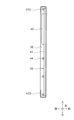
図7は、第1壁部材2を単体で示す。前記同様、第1壁部材2もその取付位置(すなわち、左壁部材2Lであるか右壁部材2Rであるか)によって向きが異なる。そこで図7(A)を、前方から見たときの前面図とし、これを基準として前後左右上下の各方向を図7(A)に示す通りに定める。図7(A)において、紙面厚さ方向手前側が前、紙面厚さ方向奥側が後、紙面に向かって右側が左、左側が右、上側が上、下側が下である。よって図7(B)は左側面図である。 Figure 7 shows the first wall member 2 alone. As before, the orientation of the first wall member 2 also differs depending on its mounting position (i.e., whether it is the left wall member 2L or the right wall member 2R). Therefore, Figure 7(A) is a front view as seen from the front, and based on this, the front, back, left, right, top and bottom directions are defined as shown in Figure 7(A). In Figure 7(A), the front side in the thickness direction of the paper is the front, the back side in the thickness direction of the paper is the back, the right side as viewed from the paper is the left, the left side is the right, the top side is the top, and the bottom side is the bottom. Therefore, Figure 7(B) is a left side view.

第1壁部材2は、その左右の端部に設けられた一対の第1支柱21と、これら第1支柱21を掛け渡すと共にこれら第1支柱21に溶接等により固定される第1壁本体22とを有する。第1壁本体22は、格子状の金属ネットにより形成され、左右および上下方向に延びている。第1壁本体22は、左右方向に延びる複数の横材22Aと、上下方向に延びる複数の縦材22Bとを格子状に組み立てて構成されている。 The first wall member 2 has a pair of first supports 21 provided at the left and right ends thereof, and a first wall body 22 that spans the first supports 21 and is fixed to the first supports 21 by welding or the like. The first wall body 22 is formed of a lattice-like metal net and extends in the left-right and up-down directions. The first wall body 22 is constructed by assembling in a lattice shape a number of horizontal members 22A extending in the left-right direction and a number of vertical members 22B extending in the up-down direction.

左右の第1支柱21は、左右対称の構成である。第1支柱21は、上下方向に延びる断面四角形(略正方形)の角管状である。第1支柱21の前面部と下面部が交差する角部には、左右方向に延びるシャフト挿通管23が溶接等により固定されている。 The left and right first pillars 21 are symmetrical. The first pillars 21 are rectangular tubular structures that extend vertically and have a rectangular (approximately square) cross section. A shaft insertion tube 23 that extends horizontally is fixed by welding or the like to the corner where the front and bottom surfaces of the first pillars 21 intersect.

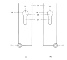
図8の(A)および(B)は、それぞれ、図7(A)のVIIIA-VIIIA断面およびVIIIB-VIIIB断面から見たときの右側および左側の第1支柱21を部分的に示す。 Figures 8 (A) and (B) show partial views of the right and left first pillars 21 as viewed from the VIIIA-VIIIA and VIIIB-VIIIB cross sections of Figure 7 (A), respectively.

図8(B)に示すように、左側の第1支柱21には、第1ロック機構4の第1ロックバー24が挿通される長穴25が設けられている。長穴25は、特殊形状を有し、上部の略円形穴26と下部長穴27とを連続的に連結して構成されている。略円形穴26の穴径は下部長穴27の穴径より大きく、下部長穴27は略円形穴26から下方に向かって延びている。 As shown in FIG. 8(B), the first support pillar 21 on the left side has an elongated hole 25 through which the first lock bar 24 of the first lock mechanism 4 is inserted. The elongated hole 25 has a special shape and is formed by continuously connecting an upper substantially circular hole 26 and a lower elongated hole 27. The diameter of the substantially circular hole 26 is larger than the diameter of the lower elongated hole 27, and the lower elongated hole 27 extends downward from the substantially circular hole 26.

略円形穴26は、完全な円形ではなく、完全な円形の穴の後端部を弦部28によって弦状に塞ぐように構成されている。 The approximately circular hole 26 is not perfectly circular, but is configured so that the rear end of the perfectly circular hole is closed in a chord shape by the chord portion 28.

こうした長穴25は、左側の第1支柱21の下端部における右側面、すなわち左右方向内側の面に設けられている。ここで、第1壁部材2の左右中心C3(パレット100の前後中心C1に相当)を想定したとき、左右方向において左右中心C3に近づく方向を左右方向内側、左右中心C3から遠ざかる方向を左右方向外側という。従って長穴25は、左右方向内側に向かって配置されている。 These long holes 25 are provided on the right side surface at the bottom end of the first support 21 on the left side, i.e., on the inner surface in the left-right direction. Here, assuming the left-right center C3 of the first wall member 2 (corresponding to the front-rear center C1 of the pallet 100), the direction approaching the left-right center C3 in the left-right direction is called the inner side in the left-right direction, and the direction moving away from the left-right center C3 is called the outer side in the left-right direction. Therefore, the long holes 25 are arranged facing inward in the left-right direction.

長穴25は基本的に、右側の第1支柱21にも左右対称で設けられている。よって左右の長穴25同士は互いに対向されている。 The long holes 25 are basically provided symmetrically on the first support pillar 21 on the right side. Therefore, the left and right long holes 25 face each other.

但し、図8(A)および(B)を見比べると分かるように、長穴25の上部の略円形穴26は左右対称ではない。図8(A)に示す右側の略円形穴26は、完全な円形の穴の前端部を弦部28によって弦状に塞ぐように構成されている。従って、左右の略円形穴26は、前後対称の形状とされ。その穴中心周りの位相が互いに180°ずれている。 However, as can be seen by comparing Figures 8(A) and (B), the approximately circular holes 26 at the top of the long holes 25 are not symmetrical. The approximately circular hole 26 on the right side shown in Figure 8(A) is configured so that the front end of the completely circular hole is closed in a chord shape by the chord portion 28. Therefore, the approximately circular holes 26 on the left and right are symmetrical in shape from front to back. The phases around the center of the holes are shifted by 180° from each other.

図7(B)に示すように、左側の第1支柱21における左側面には、完全な円形の貫通穴29が略円形穴26と同軸、同径で設けられている。貫通穴29は、右側の第1支柱21にも左右対称で設けられている。 As shown in FIG. 7B, a completely circular through-hole 29 is provided on the left side surface of the first support pillar 21 on the left side, and is coaxial with and has the same diameter as the approximately circular hole 26. A through-hole 29 is also provided symmetrically on the first support pillar 21 on the right side.

図9は、第1ロックバー24を単体で示す。ここでは図9(A)を、前方から見たときの前面図とし、これを基準として前後左右上下の各方向を図9(A)に示す通りに定める。図7(A)において、紙面厚さ方向手前側が前、紙面厚さ方向奥側が後、紙面に向かって右側が左、左側が右、上側が上、下側が下である。よって図9において(B)は右側面図、(C)は左側面図である。 Figure 9 shows the first lock bar 24 by itself. Here, Figure 9(A) is a front view as seen from the front, and based on this, the front, back, left, right, top and bottom directions are defined as shown in Figure 9(A). In Figure 7(A), the front side in the thickness direction of the paper is the front, the back side in the thickness direction of the paper is the back, the right side as you face the paper is the left, the left side is the right, the top is the top, and the bottom is the bottom. Therefore, in Figure 9, (B) is a right side view, and (C) is a left side view.

第1ロックバー24は、左右方向に延びる棒状の第1ロックバー本体30と、第1ロックバー本体30の左右の端部に嵌合され溶接等により固定された左右のフランジ板31L,31Rとを有する。第1ロックバー本体30は、断面円形の金属棒または金属パイプにより形成される。 The first lock bar 24 has a rod-shaped first lock bar body 30 extending in the left-right direction, and left and right flange plates 31L, 31R that are fitted to the left and right ends of the first lock bar body 30 and fixed by welding or the like. The first lock bar body 30 is formed from a metal rod or metal pipe with a circular cross section.

左右のフランジ板31L,31Rは、左右の略円形穴26にぴったりと嵌合挿入されるように構成され、左右の略円形穴26と同一形状を有する。そして左右のフランジ板31L,31Rは、左右の略円形穴26に対応して、第1ロックバー24の中心軸C4周りの位相が互いに180°ずれている。 The left and right flange plates 31L, 31R are configured to be tightly fitted and inserted into the left and right substantially circular holes 26, and have the same shape as the left and right substantially circular holes 26. The left and right flange plates 31L, 31R correspond to the left and right substantially circular holes 26, and are out of phase with each other by 180° around the central axis C4 of the first lock bar 24.

第1ロックバー24の取付時、第1ロックバー24は、例えば左側の第1支柱21の左側すなわち外側から、左側の貫通穴29、左側の略円形穴26という順番で挿通される。このとき第1ロックバー24の右側のフランジ板31Rと左側の略円形穴26との向きが合わせられる。これにより第1ロックバー24は左側の第1支柱21を貫通される。 When installing the first lock bar 24, the first lock bar 24 is inserted, for example, from the left side, i.e., the outside, of the left first support 21, through the left through hole 29 and the left approximately circular hole 26 in that order. At this time, the orientation of the right flange plate 31R of the first lock bar 24 and the left approximately circular hole 26 are aligned. This allows the first lock bar 24 to pass through the left first support 21.

次いで第1ロックバー24は、右側の第1支柱21に達するまで右側に向かって挿通される。そして右側の第1支柱21に達すると、第1ロックバー24がその中心軸C4周りに180°回転され、右側のフランジ板31Rと右側の略円形穴26との向きが合わせられる。 The first lock bar 24 is then inserted to the right until it reaches the first support post 21 on the right side. When it reaches the first support post 21 on the right side, the first lock bar 24 is rotated 180° around its central axis C4, and the orientation of the right flange plate 31R and the right approximately circular hole 26 are aligned.

よって第1ロックバー24を右側に挿入することで、右側のフランジ板31Rが右側の略円形穴26に挿通される。この状態だと、図7(A)に示すように、右側および左側のフランジ板31R,31Lがそれぞれ右側および左側の第1支柱21内に入っている。 Therefore, by inserting the first lock bar 24 to the right side, the right flange plate 31R is inserted into the right-side substantially circular hole 26. In this state, as shown in FIG. 7(A), the right and left flange plates 31R, 31L are respectively inserted into the right and left first support columns 21.

これにより第1ロックバー24の取り付けが完了し、第1ロックバー24は左右の第1支柱21に対し、長穴25に沿って昇降可能となる。 This completes the installation of the first lock bar 24, allowing the first lock bar 24 to move up and down along the long holes 25 relative to the left and right first pillars 21.

第1ロックバー24を一旦取り付けてしまえば、左右のフランジ板31L,31Rの向きが左右の略円形穴26の向きと合わなければ、第1ロックバー24が抜けることがなく、そうした抜去可能な位相は360°内で1箇所だけである。従って使用時に第1ロックバー24が抜けることはなく、簡素な構造で抜け止めを達成することができる。 Once the first lock bar 24 is attached, it will not come loose unless the orientation of the left and right flange plates 31L, 31R is aligned with the orientation of the left and right approximately circular holes 26, and there is only one phase in which it can be removed within 360°. Therefore, the first lock bar 24 will not come loose during use, and a simple structure can be used to prevent it from coming loose.

一方、第1ロックバー24を交換等のために抜きたい場合には、左右のフランジ板31L,31Rと略円形穴26の位相合わせをすることにより、それを容易に行える。従って第1ロックバー24のメンテナンスを容易に行うことができる。 On the other hand, if you want to remove the first lock bar 24 for replacement or other reasons, this can be easily done by aligning the phase of the left and right flange plates 31L, 31R with the approximately circular hole 26. This makes it easy to perform maintenance on the first lock bar 24.

第1ロックバー24は作業者により操作される部材である。そのため、第1ロックバー24を第1壁部材2から容易に区別できるよう、第1ロックバー24は第1壁部材2と異なる色で着色されるのが好ましい。 The first lock bar 24 is a member that is operated by an operator. Therefore, it is preferable that the first lock bar 24 is colored a different color from the first wall member 2 so that the first lock bar 24 can be easily distinguished from the first wall member 2.

なお、ここでは第1ロックバー24を左側から右側に向かって挿通させたが、逆に、右側から左側に向かって挿通させてもよい。 Note that here, the first lock bar 24 is inserted from the left side to the right side, but it may be inserted from the right side to the left side instead.

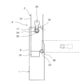
図1および図7に示すように、第1壁部材2は、前述の第2ロック機構5の第2ロックバー32が係合される上部ブラケット33Uおよび下部ブラケット33Dを有する。これら上部ブラケット33Uおよび下部ブラケット33Dは、左右の第1支柱21に左右対称で配置され、溶接等により固定されている。 As shown in Figures 1 and 7, the first wall member 2 has an upper bracket 33U and a lower bracket 33D with which the second lock bar 32 of the second lock mechanism 5 described above is engaged. These upper brackets 33U and lower brackets 33D are arranged symmetrically on the left and right first pillars 21 and are fixed by welding or the like.

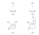
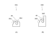
図10は、左側の第1壁部材2における上部ブラケット33Uおよび下部ブラケット33Dを示し、(1A)は上部ブラケット33Uの前面図、(1B)は上部ブラケット33Uの上面図、(2A)は下部ブラケット33Dの前面図、(2B)は下部ブラケット33Dの上面図である。 Figure 10 shows the upper bracket 33U and lower bracket 33D of the first wall member 2 on the left side, where (1A) is a front view of the upper bracket 33U, (1B) is a top view of the upper bracket 33U, (2A) is a front view of the lower bracket 33D, and (2B) is a top view of the lower bracket 33D.

これらブラケット33U,33Dは、金属板により上面視コ字状に形成されている。ブラケット33U,33Dの上端面部には、その左右方向の中心部に位置された第2スロット34U,34Dと、第2スロット34U,34Dの右側(左右方向内側)に隣接して位置された第2カム面35U,35Dとが設けられている。 These brackets 33U, 33D are made of metal plate and are U-shaped when viewed from above. The upper end surface of the brackets 33U, 33D is provided with a second slot 34U, 34D located in the center in the left-right direction, and a second cam surface 35U, 35D located adjacent to the right side (inner side in the left-right direction) of the second slot 34U, 34D.

詳しくは後述するが、第2スロット34U,34Dは、第2ロックバー32が昇降可能に挿通されるスロットである。第2カム面35U,35Dは、第2壁部材3の起立時に第2ロックバー32を第2スロット34U,34Dに向かって案内するカム面である。本実施形態の場合、第2カム面35U,35Dは、右側(左右方向内側)から左側(左右方向外側)に向かって徐々に高くなる直線状傾斜面によって形成されている。また下側の第2カム面35Dの傾斜角θ1は上側の第2カム面35Dの傾斜角θ2より大きくされている。 As will be described in detail later, the second slots 34U, 34D are slots through which the second lock bar 32 is inserted so as to be able to rise and fall. The second cam surfaces 35U, 35D are cam surfaces that guide the second lock bar 32 toward the second slots 34U, 34D when the second wall member 3 is raised. In this embodiment, the second cam surfaces 35U, 35D are formed by linearly inclined surfaces that gradually become higher from the right side (inner side in the left-right direction) to the left side (outer side in the left-right direction). The inclination angle θ1 of the lower second cam surface 35D is set to be larger than the inclination angle θ2 of the upper second cam surface 35D.

第1壁部材2を底板部材1に取り付ける際には、第1ロックバー24が第1壁部材2に予め取り付けられる。次に、この第1壁部材2の前面(図7(A)の紙面厚さ方向手前側の面)が、底板部材1の左右方向内側を向くように(図1参照)、第1壁部材2が底板部材1の左右の端部に取り付けられる。このとき、図22にも示すように、第1壁部材2の第1支柱21が、底板部材1の支柱受け6に上方から嵌合挿入される。そして第1壁部材2のシャフト挿通管23と、底板部材1の貫通穴16L,16Rとに、回動シャフト36が挿通される。これにより第1壁部材2は底板部材1に回動可能に接続される。なお回動シャフト36は支柱受け6に溶接等により固定される。 When attaching the first wall member 2 to the bottom plate member 1, the first lock bar 24 is attached to the first wall member 2 in advance. Next, the first wall member 2 is attached to the left and right ends of the bottom plate member 1 so that the front surface of the first wall member 2 (the surface on the front side in the thickness direction of the paper in FIG. 7(A)) faces the inside in the left and right direction of the bottom plate member 1 (see FIG. 1). At this time, as also shown in FIG. 22, the first support 21 of the first wall member 2 is inserted and fitted into the support receiver 6 of the bottom plate member 1 from above. Then, the rotating shaft 36 is inserted through the shaft insertion tube 23 of the first wall member 2 and the through holes 16L and 16R of the bottom plate member 1. As a result, the first wall member 2 is connected to the bottom plate member 1 in a rotatable manner. The rotating shaft 36 is fixed to the support receiver 6 by welding or the like.

第1壁部材2は、図1,2に示すような起立状態と、起立状態から左右方向内側(左右中心C2に向かう方向)に略90°転倒する折り畳み状態もしくは転倒状態との間で回動可能である。第1壁部材2は、パレット100の使用時には起立状態とされ、パレット100の不使用時や保管時等には折り畳み状態とされる。 The first wall member 2 can rotate between an upright state as shown in Figs. 1 and 2 and a folded or inverted state in which it is inverted approximately 90° inwardly from the upright state (towards the left-right center C2). The first wall member 2 is in the upright state when the pallet 100 is in use and in the folded state when the pallet 100 is not in use or is in storage.

図20には、第1壁部材2の第1支柱21と、第1ロック機構4の第1ロックバー24と、底板部材1の支柱受け6との取付状態を透過的に示す。起立状態にある第1壁部材2を実線で示し、折り畳み状態にある第1壁部材2を仮想線で示す。起立状態では、第1支柱21が、支柱載置金具15の上に載置され、第1壁部材2の重量の一部が支柱載置金具15によって下方から支持される。そして第1ロックバー24の第1ロックバー本体30が第1スロット17に挿入され、第1壁部材2が起立状態でロックされる。 Figure 20 shows the attachment state of the first support 21 of the first wall member 2, the first lock bar 24 of the first lock mechanism 4, and the support support 6 of the bottom plate member 1 in a transparent manner. The first wall member 2 in the upright state is shown in solid lines, and the first wall member 2 in the folded state is shown in imaginary lines. In the upright state, the first support 21 is placed on the support support bracket 15, and part of the weight of the first wall member 2 is supported from below by the support support bracket 15. The first lock bar body 30 of the first lock bar 24 is then inserted into the first slot 17, and the first wall member 2 is locked in the upright state.

図23には、第1壁部材2が起立状態にあるときの第1支柱21と、第1ロックバー24と、支柱受け6との取付状態を断面図で示す。第1ロックバー24のフランジ板31Lが第1支柱21の内部に位置されるので、第1ロックバー24が長穴25から抜けることがない。そして第1ロックバー24の第1ロックバー本体30は、長穴25の下部長穴27と、第1スロット17とに挿通され、それらの下端部に位置される。 Figure 23 shows a cross-sectional view of the first support 21, the first lock bar 24, and the support support 6 when the first wall member 2 is in an upright position. The flange plate 31L of the first lock bar 24 is positioned inside the first support 21, so the first lock bar 24 does not come out of the long hole 25. The first lock bar body 30 of the first lock bar 24 is inserted through the lower long hole 27 of the long hole 25 and the first slot 17, and is positioned at their lower ends.

次に、図11~図16を用いて第2壁部材3を説明する。 Next, the second wall member 3 will be explained using Figures 11 to 16.

図11は、第2壁部材3を単体で示す。前記同様、第2壁部材3もその取付位置(すなわち、前壁部材2Fであるか後壁部材であるか)によって向きが異なる。そこで図11(A)を、前方から見たときの前面図とし、これを基準として前後左右上下の各方向を図7(A)に示す通りに定める。図7(A)において、紙面厚さ方向手前側が前、紙面厚さ方向奥側が後、紙面に向かって右側が左、左側が右、上側が上、下側が下である。よって図11(B)は左側面図である。 Figure 11 shows the second wall member 3 alone. As before, the orientation of the second wall member 3 also differs depending on its mounting position (i.e., whether it is the front wall member 2F or the rear wall member). Therefore, Figure 11(A) is a front view as seen from the front, and based on this, the front, back, left, right, top and bottom directions are defined as shown in Figure 7(A). In Figure 7(A), the front side in the thickness direction of the paper is the front, the back side in the thickness direction of the paper is the back, the right side as viewed from the paper is the left, the left side is the right, the top side is the top, and the bottom side is the bottom. Therefore, Figure 11(B) is a left side view.

図12、図13および図16でも同様、(A)が前面図、(B)が左側面図である。図14は図13のXIV-XIV断面図、図15は前面図である。 Similarly, in Figures 12, 13, and 16, (A) is a front view and (B) is a left side view. Figure 14 is a cross-sectional view taken along line XIV-XIV in Figure 13, and Figure 15 is a front view.

図11に示すように、第2壁部材3は上下に二分割され、上側第2壁部材3Uと下側第2壁部材3Dとから構成されている。上側第2壁部材3Uと下側第2壁部材3Dは、複数(3つ)のヒンジ37によって互いに回動可能に接続されている。こうして第2壁部材3は、互いに回動可能に接続された上側第2壁部材3Uおよび下側第2壁部材3Dを有することとなる。 As shown in FIG. 11, the second wall member 3 is divided into two parts, an upper part and a lower part, and is composed of an upper second wall member 3U and a lower second wall member 3D. The upper second wall member 3U and the lower second wall member 3D are rotatably connected to each other by multiple (three) hinges 37. In this way, the second wall member 3 has an upper second wall member 3U and a lower second wall member 3D that are rotatably connected to each other.

上側第2壁部材3Uと下側第2壁部材3Dの構成はほぼ同一なので、以下、上側第2壁部材3Uを中心に説明する。 The upper second wall member 3U and the lower second wall member 3D have almost the same configuration, so the following explanation will focus on the upper second wall member 3U.

図12に示すように、上側第2壁部材3Uは、その左右の端部に設けられた一対の第2支柱38と、これら第2支柱38を掛け渡すと共にこれら第2支柱38に溶接等により固定される第2壁本体39とを有する。第2壁本体39は、格子状の金属ネットにより形成され、左右および上下方向に延びている。 As shown in FIG. 12, the upper second wall member 3U has a pair of second supports 38 provided at the left and right ends thereof, and a second wall body 39 that spans the second supports 38 and is fixed to the second supports 38 by welding or the like. The second wall body 39 is formed of a lattice-shaped metal net and extends in the left-right and up-down directions.

上側第2壁部材3Uには、第2ロック機構5を構成する第2ロックバー40が昇降可能に設けられている。第2ロックバー40は、左右の第2支柱38を掛け渡すと共に、左右の第2支柱38に昇降可能に設けられている。図13は、上側第2壁部材3Uを単品で示し、図15は、第2ロックバー40を単品で示す。 A second lock bar 40 constituting the second lock mechanism 5 is provided on the upper second wall member 3U so that it can rise and fall. The second lock bar 40 spans the left and right second support posts 38 and is provided on the left and right second support posts 38 so that it can rise and fall. Figure 13 shows the upper second wall member 3U alone, and Figure 15 shows the second lock bar 40 alone.

図13および図14に示すように、上側第2壁部材3Uにおける左右の第2支柱38は、左右対称の構成である。第2支柱38は、上下方向に延びる長方形板状である。左右の第2支柱38の間に第2壁本体39が挟まれ、溶接等により固定されている。また左右の第2支柱38の間に、第2壁本体39の上端部および下端部を覆うカバー41U、41Dが挟まれ、溶接等により固定されている。 As shown in Figures 13 and 14, the left and right second pillars 38 in the upper second wall member 3U are symmetrical. The second pillars 38 are rectangular plates extending in the vertical direction. The second wall body 39 is sandwiched between the left and right second pillars 38 and fixed thereto by welding or the like. In addition, covers 41U and 41D that cover the upper and lower ends of the second wall body 39 are sandwiched between the left and right second pillars 38 and fixed thereto by welding or the like.

第2支柱38には、第2ロックバー40が挿通される長穴42が設けられている。長穴42は、上下方向に延びる直線状の長穴であり、第2ロックバー40と第2壁本体39が干渉しないよう、第2壁本体39の後方に隣接して設けられている。 The second support 38 has an elongated hole 42 through which the second lock bar 40 is inserted. The elongated hole 42 is a straight elongated hole that extends vertically and is provided adjacent to the rear of the second wall body 39 so that the second lock bar 40 and the second wall body 39 do not interfere with each other.

長穴42は、右側の第2支柱38にも左右対称で設けられている。よって左右の長穴38同士は互いに対向されている。 The long hole 42 is also provided symmetrically in the second support pillar 38 on the right side. Therefore, the left and right long holes 38 face each other.

第2壁本体39は、複数の縦材43と横材44を格子状に組み立てて構成されている。一方、第2壁本体39の上半部には、横材44が所定本数(本実施形態では2本)欠損された欠損部45が形成されている。この欠損部45に、はしご状の第2ロックバー40が配置されることで、あたかも欠損部45がないかのような外観を呈している。 The second wall body 39 is constructed by assembling a number of vertical members 43 and horizontal members 44 in a lattice pattern. Meanwhile, the upper half of the second wall body 39 has a missing portion 45 formed by removing a certain number of horizontal members 44 (two in this embodiment). A ladder-shaped second lock bar 40 is placed in this missing portion 45, giving the appearance of there being no missing portion 45.

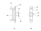
図15および図16に示すように、第2ロックバー40は、全体として左右方向に延びるはしご状の形状を有している。第2ロックバー40は、その左右の端部に設けられ上下方向に延びる一対の端板46と、左右方向に延びてこれら端板46を掛け渡すと共にこれら端板46に溶接等により固定される上下一対のロックバー横材47と、これらロックバー横材47を連結する複数のロックバー縦材48とを有する。 As shown in Figures 15 and 16, the second lock bar 40 has a ladder-like shape that extends in the left-right direction as a whole. The second lock bar 40 has a pair of end plates 46 that are provided at the left and right ends and extend in the up-down direction, a pair of upper and lower lock bar horizontal members 47 that extend in the left-right direction, span the end plates 46, and are fixed to the end plates 46 by welding or the like, and a number of lock bar vertical members 48 that connect the lock bar horizontal members 47.

また第2ロックバー40は、左右の端板46から左右方向の外側(第2壁部材3の左右中心C5(パレット100の左右中心C2に相当))から遠ざかる方向)に突出されたロックピン49と、ロックピン49の左右方向の外側の先端部に溶接等により固定されるフランジ50とを有する。 The second lock bar 40 also has a lock pin 49 that protrudes outward in the left-right direction from the left and right end plates 46 (in a direction away from the left-right center C5 of the second wall member 3 (corresponding to the left-right center C2 of the pallet 100)), and a flange 50 that is fixed to the left-right outer tip of the lock pin 49 by welding or the like.

ロックバー横材47、ロックバー縦材48およびロックピン49は、断面円形かつ金属製の棒により形成される。上下のロックバー横材47同士の間隔は、横材44同士の間隔と等しくされる。ロックバー縦材48の左右方向の位置および間隔は、縦材43の左右方向の位置および間隔と等しくされる。 The lock bar horizontal members 47, the lock bar vertical members 48, and the lock pins 49 are formed from metal rods with a circular cross section. The distance between the upper and lower lock bar horizontal members 47 is made equal to the distance between the horizontal members 44. The left-right position and distance of the lock bar vertical members 48 are made equal to the left-right position and distance of the vertical members 43.

第2ロックバー40は作業者により操作される部材である。そのため、第2ロックバー40を第2壁本体39から容易に区別できるよう、第2ロックバー40は第2壁本体39と異なる色で着色されるのが好ましい。 The second lock bar 40 is a member that is operated by an operator. Therefore, it is preferable that the second lock bar 40 is colored a different color from the second wall body 39 so that the second lock bar 40 can be easily distinguished from the second wall body 39.

以上の構成は、上側第2壁部材3Uと下側第2壁部材3Dで同一である。そのため第2ロック機構5は、上側第2壁部材3Uと下側第2壁部材3Dに個別に設けられる。 The above configuration is the same for the upper second wall member 3U and the lower second wall member 3D. Therefore, the second locking mechanism 5 is provided separately for the upper second wall member 3U and the lower second wall member 3D.

図11に示すように、上側第2壁部材3Uの下側カバー41Dと、下側第2壁部材3Dの上側カバー41Uとの前面部に、複数(3つ)のヒンジ37が取り付けられる。 As shown in FIG. 11, multiple (three) hinges 37 are attached to the front portions of the lower cover 41D of the upper second wall member 3U and the upper cover 41U of the lower second wall member 3D.

加えて、下側第2壁部材3Dの底部かつ左右両端部には回動シャフト51が設けられる。回動シャフト51は、金属棒を折り曲げて形成され、第2壁部材3Dより後方かつ僅かに下方の位置において左右方向に延びる係合部52を有する。 In addition, a pivot shaft 51 is provided at the bottom and both left and right ends of the second lower wall member 3D. The pivot shaft 51 is formed by bending a metal rod and has an engagement portion 52 that extends in the left-right direction at a position rearward and slightly below the second wall member 3D.

また、下側第2壁部材3Dの上側カバー41Uには、下側第2壁部材3Dが転倒されたときに底板部材1に当接して衝撃を吸収すると共に傷付きを防止する複数(2つ)の緩衝材53が設けられる。緩衝材53はゴム等の弾性材料により形成されている。なお、こうした緩衝材は、相手方の部材に当接する他の部材にも適宜設けることができる。 The upper cover 41U of the lower second wall member 3D is provided with multiple (two) cushioning materials 53 that come into contact with the bottom plate member 1 when the lower second wall member 3D is overturned to absorb the impact and prevent damage. The cushioning materials 53 are made of an elastic material such as rubber. Note that such cushioning materials can also be provided as appropriate on other members that come into contact with opposing members.

第2壁部材3を底板部材1に取り付ける際、まず、第2ロックバー40が上側第2壁部材3Uと下側第2壁部材3Dに同様の方法で取り付けられる。 When attaching the second wall member 3 to the bottom plate member 1, the second lock bar 40 is first attached to the upper second wall member 3U and the lower second wall member 3D in a similar manner.

例えば第2ロックバー40を上側第2壁部材3Uに取り付ける場合、上側第2壁部材3Uの左右の長穴42に、第2ロックバー40の上下のロックバー横材47が挿通される。そして、左右の長穴42から突出された上下のロックバー横材47の左右の端部に、左右の端板46が溶接等により固定される。左右の端板46には、ロックピン49およびフランジ50が予め溶接等により固定されている。これにより第2ロックバー40は、左右の第2支柱38に、長穴42に沿って昇降可能かつスライド可能に取り付けられる。 For example, when attaching the second lock bar 40 to the upper second wall member 3U, the upper and lower lock bar cross members 47 of the second lock bar 40 are inserted into the left and right long holes 42 of the upper second wall member 3U. Then, the left and right end plates 46 are fixed by welding or the like to the left and right ends of the upper and lower lock bar cross members 47 protruding from the left and right long holes 42. The left and right end plates 46 have lock pins 49 and flanges 50 fixed in advance by welding or the like. In this way, the second lock bar 40 is attached to the left and right second supports 38 so that it can move up and down and slide along the long holes 42.

第2壁部材3が起立状態のとき、第2ロックバー40は長穴42の下端部に位置される。このとき、ロックバー横材47と横材44が全体として等間隔で配置され、ロックバー縦材48と縦材43が同一位置に配置される。よって違和感のない外観を呈することができる。 When the second wall member 3 is in an upright position, the second lock bar 40 is positioned at the lower end of the long hole 42. At this time, the lock bar horizontal members 47 and horizontal members 44 are positioned at equal intervals overall, and the lock bar vertical members 48 and vertical members 43 are positioned in the same position. This provides a natural appearance.

こうして第2ロックバー40を上側第2壁部材3Uと下側第2壁部材3Dに取り付けた後、複数のヒンジ37が、上側第2壁部材3Uの下側カバー41Dの前面と、下側第2壁部材3Dの上側カバー41Uの前面とに固定される。これにより第2壁部材3の組み立てが完了する。 After the second lock bar 40 is attached to the upper second wall member 3U and the lower second wall member 3D in this manner, the multiple hinges 37 are fixed to the front surface of the lower cover 41D of the upper second wall member 3U and the front surface of the upper cover 41U of the lower second wall member 3D. This completes the assembly of the second wall member 3.

次に、完成した第2壁部材3を底板部材1の前後の端部に同様の方法で取り付ける。このとき、前後の第2壁部材3の前面(図11(A)の前面)が、前後方向内側(前後中心C1に近づく方向)を向くよう、前後の第2壁部材3が配置される。言い換えれば、前後の第2壁部材3の前面同士が互いに対向するように前後の第2壁部材3が配置される。 Next, the completed second wall members 3 are attached to the front and rear ends of the bottom plate member 1 in a similar manner. At this time, the front and rear second wall members 3 are positioned so that their front faces (front faces in FIG. 11(A)) face inward in the front-to-rear direction (the direction approaching the front-to-rear center C1). In other words, the front and rear second wall members 3 are positioned so that their front faces face each other.

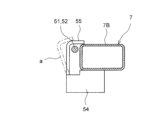
また、図17に示すように、底板部材1の底板フレーム7にはブラケット54が予め取り付けられ、このブラケット54のアーム55と底板フレーム7により囲まれたスペースに、回動シャフト51の係合部52が挿入される。ブラケット54のアーム55は、最初は係合部52が挿入できるよう、仮想線aで示すように開いており、係合部52の挿入後、根元から折り曲げられて底板フレーム7に当接され、溶接等により固定される。これによりスペースが閉空間となり回動シャフト51が抜け止めされる。こうして第2壁部材3が底板部材1に回動可能に取り付けられる。 As shown in FIG. 17, a bracket 54 is attached in advance to the bottom plate frame 7 of the bottom plate member 1, and the engagement portion 52 of the rotating shaft 51 is inserted into the space surrounded by the arm 55 of this bracket 54 and the bottom plate frame 7. The arm 55 of the bracket 54 is initially open as shown by the imaginary line a so that the engagement portion 52 can be inserted, and after the engagement portion 52 is inserted, it is bent from the base and abutted against the bottom plate frame 7 and fixed by welding or the like. This closes the space and prevents the rotating shaft 51 from coming loose. In this way, the second wall member 3 is rotatably attached to the bottom plate member 1.

図3に示すように、ブラケット54は、前後の第2壁部材3の回動シャフト51に対応した位置に設けられる。すなわち、ブラケット54は、底板フレーム7の前後のクロスメンバ7Bにおける前後方向内側の面にアーム55が対向するように設けられる。 As shown in FIG. 3, the brackets 54 are provided at positions corresponding to the pivot shafts 51 of the front and rear second wall members 3. In other words, the brackets 54 are provided so that the arms 55 face the inner surfaces of the front and rear cross members 7B of the bottom frame 7 in the fore-and-aft direction.

次に、第1壁部材2を起立状態でロックすると共に、第2壁部材3を起立させ、上下の第2ロックバー40のロックピン49を、第1壁部材2の上部ブラケット33Uおよび下部ブラケット33Dに係合させる。このとき、上下のロックピン49の先端のフランジ50を上部ブラケット33Uおよび下部ブラケット33Dの中に挿入しつつ、上下のロックピン49を、上部ブラケット33Uおよび下部ブラケット33の第2スロット34U,34Dに上方から挿入する。これにより上下の第2ロックバー40が上部ブラケット33Uおよび下部ブラケット33Dに係合し、第2壁部材3は起立状態で第1壁部材2に対しロックされる。 Next, the first wall member 2 is locked in an upright position, and the second wall member 3 is raised, and the lock pins 49 of the upper and lower second lock bars 40 are engaged with the upper bracket 33U and lower bracket 33D of the first wall member 2. At this time, the flanges 50 at the ends of the upper and lower lock pins 49 are inserted into the upper bracket 33U and lower bracket 33D, while the upper and lower lock pins 49 are inserted from above into the second slots 34U, 34D of the upper bracket 33U and lower bracket 33. As a result, the upper and lower second lock bars 40 engage with the upper bracket 33U and lower bracket 33D, and the second wall member 3 is locked to the first wall member 2 in an upright position.

次に、本実施形態に係るパレット100の使用方法を説明する。 Next, we will explain how to use the pallet 100 according to this embodiment.

まず、第1壁部材2および第2壁部材3が起立状態にあるパレット100を折り畳むときの折り畳み方法を説明する。 First, we will explain how to fold the pallet 100 when the first wall member 2 and the second wall member 3 are in an upright position.

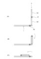
まず、前後の第2壁部材3を折り畳む。ここでは前側の第2壁部材3を先に折り畳むものとする。図18には折り畳み時の様子を模式的に示す。図18(A)は、初期の起立状態にある第2壁部材3を示す。 First, the front and rear second wall members 3 are folded. In this example, the front second wall member 3 is folded first. Figure 18 shows a schematic diagram of the state when folded. Figure 18(A) shows the second wall member 3 in the initial standing state.

このとき、作業者はパレット100の前方(図1の紙面厚さ方向手前側)に立ち、上側第2壁部材3Uの第2ロックバー40を引き上げて、第1壁部材2に対する上側第2壁部材3Uのロックを解除する。例えば、作業者は、第2ロックバー40の上側のロックバー横材47と、その直上にある上側第2壁部材3Uの上側カバー41U(図11参照)とを、前方から両手で握ることにより、第2ロックバー40を水平に引き上げる。これにより、第2ロックバー40における左右のロックピン49が、上部ブラケット33Uの第2スロット34Uから引き抜かれ、ロックが解除される。後はロックバー横材47と上側カバー41Uとを両手で握りながら、図18(B)に示すように、静かに上側第2壁部材3Uを前方(作業者に近づく方向)に向かって倒す。これにより、上側第2壁部材3Uがヒンジ37によって下側第2壁部材3Dに対し回動し、上側第2壁部材3Uが下側第2壁部材3Dの前側に重ねられる。 At this time, the worker stands in front of the pallet 100 (the front side in the thickness direction of the paper in FIG. 1) and pulls up the second lock bar 40 of the upper second wall member 3U to release the lock of the upper second wall member 3U to the first wall member 2. For example, the worker holds the upper lock bar cross member 47 of the second lock bar 40 and the upper cover 41U of the upper second wall member 3U directly above it (see FIG. 11) with both hands from the front to pull up the second lock bar 40 horizontally. This causes the left and right lock pins 49 of the second lock bar 40 to be pulled out of the second slot 34U of the upper bracket 33U, and the lock is released. Then, while holding the lock bar cross member 47 and the upper cover 41U with both hands, the worker gently tilts the upper second wall member 3U forward (toward the worker) as shown in FIG. 18 (B). As a result, the upper second wall member 3U rotates relative to the lower second wall member 3D via the hinge 37, and the upper second wall member 3U is stacked on the front side of the lower second wall member 3D.

次に、下側第2壁部材3Uの第2ロックバー40を引き上げて、第1壁部材2に対する下側第2壁部材3Uのロックを解除する。このとき作業者は、下側第2壁部材3Uの後方から、第2ロックバー40の上側のロックバー横材47と、その直上にある下側第2壁部材3Uの上側カバー41U(図11参照)とを両手で握ることにより、第2ロックバー40を水平に引き上げる。これにより、第2ロックバー40における左右のロックピン49が、下部ブラケット33Dの第2スロット34Dから引き抜かれ、ロックが解除される。後はロックバー横材47と上側カバー41Uとを両手で握りながら、図18(C)に示すように、静かに下側第2壁部材3Dを後方(作業者から遠ざかる方向)に向かって倒す。これにより、下側第2壁部材3Dが回動シャフト51の係合部52を中心に底板部材1に対し回動し、下側第2壁部材3Dが上側第2壁部材3Uと共に底板部材1の上に積み重ねられる。 Next, the second lock bar 40 of the lower second wall member 3U is pulled up to release the lock of the lower second wall member 3U against the first wall member 2. At this time, the worker pulls up the second lock bar 40 horizontally from behind the lower second wall member 3U by gripping the upper lock bar cross member 47 of the second lock bar 40 and the upper cover 41U of the lower second wall member 3U directly above it (see FIG. 11) with both hands. This causes the left and right lock pins 49 of the second lock bar 40 to be pulled out of the second slot 34D of the lower bracket 33D, and the lock is released. Then, while holding the lock bar cross member 47 and the upper cover 41U with both hands, the worker gently tilts the lower second wall member 3D backward (away from the worker) as shown in FIG. 18(C). As a result, the lower second wall member 3D rotates relative to the bottom plate member 1 around the engagement portion 52 of the rotating shaft 51, and the lower second wall member 3D is stacked on top of the bottom plate member 1 together with the upper second wall member 3U.

こうして、下側第2壁部材3Dの上に上側第2壁部材3Uが積み重なった状態で、これらが底板部材1の上に積み重ねられ、第2壁部材3が折り畳まれる。こうした第2壁部材3の状態を折り畳み状態または転倒状態という。 In this way, with the upper second wall member 3U stacked on top of the lower second wall member 3D, these are stacked on top of the bottom plate member 1, and the second wall member 3 is folded. This state of the second wall member 3 is called the folded state or overturned state.

他方、後側の第2壁部材3も、前後逆であることを除き、同様の手順で底板部材1の上に折り畳まれる。よって詳細な説明は省略する。なお、折り畳まれた前後の第2壁部材3は互いに干渉しない。 On the other hand, the rear second wall member 3 is folded onto the bottom plate member 1 in a similar manner, except that the front and rear are reversed. Therefore, a detailed explanation is omitted. The folded front and rear second wall members 3 do not interfere with each other.

次に、左右の第1壁部材2を折り畳む。ここではまず左側の第1壁部材2(左壁部材2L)を折り畳むものとする。図19には折り畳み時の様子を模式的に示す。図19(A)は、初期の起立状態にある第1壁部材2を示す。 Next, the left and right first wall members 2 are folded. In this example, the left first wall member 2 (left wall member 2L) is folded first. Figure 19 shows a schematic diagram of the state when folded. Figure 19(A) shows the first wall member 2 in the initial upright state.

このとき、作業者はパレット100の左側(図2の紙面厚さ方向手前側)に立ち、第1ロックバー24を引き上げて、底板部材1に対する第1壁部材2のロックを解除する。例えば、作業者は、第1ロックバー24の第1ロックバー本体30と、その直上にある第1壁部材2の横材22A(図2参照)とを、左側から両手で握ることにより、第1ロックバー24を水平に引き上げる。これにより、第1ロックバー24における第1ロックバー本体30の左右の端部が、左右の支柱受け6の第1スロット17から引き抜かれ、ロックが解除される。後は第1壁部材2の上端部を片手で掴みながら、図19(B)に示すように、静かに第1壁部材2を右側(作業者から遠ざかる方向)に向かって倒す。これにより、第1壁部材2は回動シャフト36によって支柱受け6ひいては底板部材1に対し回動し、転倒され、第1壁部材2が、既に底板部材1上にある上側第2壁部材3Uの上に積み重ねられる。 At this time, the worker stands on the left side of the pallet 100 (the front side in the thickness direction of the paper in FIG. 2) and pulls up the first lock bar 24 to release the lock of the first wall member 2 to the bottom plate member 1. For example, the worker holds the first lock bar body 30 of the first lock bar 24 and the cross member 22A (see FIG. 2) of the first wall member 2 directly above it with both hands from the left side, and pulls up the first lock bar 24 horizontally. This causes the left and right ends of the first lock bar body 30 of the first lock bar 24 to be pulled out of the first slots 17 of the left and right support brackets 6, and the lock is released. Then, while holding the upper end of the first wall member 2 with one hand, the first wall member 2 is gently tilted to the right (away from the worker) as shown in FIG. 19(B). As a result, the first wall member 2 rotates and falls over relative to the support 6 and thus the bottom plate member 1 by the pivot shaft 36, and the first wall member 2 is stacked on top of the upper second wall member 3U that is already on the bottom plate member 1.

こうして、第1壁部材2が折り畳まれる。こうした第1壁部材2の状態を折り畳み状態または転倒状態という。図20には、起立状態にある第1壁部材2を実線で示し、折り畳み状態にある第1壁部材2を仮想線で示す。 In this way, the first wall member 2 is folded. This state of the first wall member 2 is called the folded state or the fallen state. In FIG. 20, the first wall member 2 in the upright state is shown by a solid line, and the first wall member 2 in the folded state is shown by a virtual line.

他方、右側の第1壁部材2(右壁部材2R)も、左右逆であることを除き、同様の手順で折り畳まれる。よって詳細な説明は省略する。なお、折り畳まれた左右の第1壁部材2は互いに干渉しない。 On the other hand, the first wall member 2 on the right side (right wall member 2R) is folded in a similar manner, except that the left and right are reversed. Therefore, a detailed explanation is omitted. The folded left and right first wall members 2 do not interfere with each other.

次に、折り畳み状態にある第1壁部材2および第2壁部材3を起立させるときの起立方法を説明する。これは基本的に、前述の折り畳み方法と逆の手順を行う。 Next, we will explain how to raise the first wall member 2 and the second wall member 3 from the folded state. This is basically the reverse of the folding method described above.

まず、左右の第1壁部材2を起立させる。ここではまず左側の第1壁部材2(左壁部材2L)を起立させるものとする。 First, the left and right first wall members 2 are erected. In this example, the left first wall member 2 (left wall member 2L) is erected first.

このとき、作業者はパレット100の左側に立ち、第1壁部材2の上端部を掴んで、そのまま引き起こすだけである。これにより第1壁部材2は、回動シャフト36によって支柱受け6ひいては底板部材1に対し回動し起立する。 At this time, the worker stands on the left side of the pallet 100, grabs the upper end of the first wall member 2, and simply lifts it up. This causes the first wall member 2 to rotate and stand up relative to the support column receiver 6 and the bottom plate member 1 by the pivot shaft 36.

このとき、第1ロックバー24は、何等操作しなくても自動的にロックされる。すなわち、第1壁部材2の回動中、第1ロックバー24における第1ロックバー本体30の左右の端部が、図20に仮想線で示すように、左右の支柱受け6のカム面18上を滑り上がり、第1スロット17に向かって案内される。そして第1ロックバー本体30の端部が、第1スロット17の上端入口に達すると、第1ロックバー24が自重で降下し、第1ロックバー本体30が第1スロット17に挿入される。これにより第1ロックバー24がロックされ、第1壁部材2は起立状態でロックされる。 At this time, the first lock bar 24 is automatically locked without any operation. That is, while the first wall member 2 is rotating, the left and right ends of the first lock bar body 30 of the first lock bar 24 slide up the cam surfaces 18 of the left and right support column receivers 6 as shown by phantom lines in FIG. 20, and are guided toward the first slot 17. Then, when the ends of the first lock bar body 30 reach the upper end entrance of the first slot 17, the first lock bar 24 descends under its own weight, and the first lock bar body 30 is inserted into the first slot 17. This locks the first lock bar 24, and the first wall member 2 is locked in the upright position.

他方、右側の第1壁部材2も、左右逆であることを除き、同様の手順でロックされる。よって詳細な説明は省略する。 On the other hand, the first wall member 2 on the right side is locked in a similar manner, except that the left and right are reversed. Therefore, a detailed explanation is omitted.

次に、前後の第2壁部材3を起立させる。ここでは前側の第2壁部材3を先に起立させるものとする。 Next, the front and rear second wall members 3 are erected. In this example, the front second wall member 3 is erected first.

このとき、作業者はパレット100の前方に立ち、上段に積み重ねられた上側第2壁部材3Uの上端部を掴んで、そのまま引き上げるだけである。これにより、上側第2壁部材3Uはヒンジ37によって下側第2壁部材3Dに対し回動し、下側第2壁部材3Dは回動シャフト51の係合部52によって底板部材1に対し回動し、上側第2壁部材3Uと下側第2壁部材3Dは同時に起立される。 At this time, the worker stands in front of the pallet 100, grabs the top end of the upper second wall member 3U stacked on the top tier, and simply pulls it up. As a result, the upper second wall member 3U rotates relative to the lower second wall member 3D by the hinge 37, and the lower second wall member 3D rotates relative to the bottom plate member 1 by the engagement portion 52 of the pivot shaft 51, so that the upper second wall member 3U and the lower second wall member 3D are erected at the same time.

このとき、上下の第2ロックバー40は、何等操作しなくても自動的にロックされる。すなわち、下側第2壁部材3Dの第2ロックバー40については、下側第2壁部材3Dの回動中、第2ロックバー40における左右のロックピン49が、図21(B)に示すように、下部ブラケット33Dのカム面35D上を滑り上がり、第2スロット34Dに向かって案内される。そしてロックピン49が、第2スロット34Dの上端入口に達すると、第2ロックバー40が自重で降下し、ロックピン49が第2スロット34Dに挿入される。これにより第2ロックバー40がロックされ、下側第2壁部材3Dは起立状態でロックされる。 At this time, the upper and lower second lock bars 40 are automatically locked without any operation. That is, for the second lock bar 40 of the lower second wall member 3D, while the lower second wall member 3D is rotating, the left and right lock pins 49 of the second lock bar 40 slide up the cam surface 35D of the lower bracket 33D and are guided toward the second slot 34D, as shown in FIG. 21(B). Then, when the lock pins 49 reach the upper end entrance of the second slot 34D, the second lock bar 40 descends under its own weight and the lock pins 49 are inserted into the second slot 34D. This locks the second lock bar 40, and the lower second wall member 3D is locked in the upright position.

上側第2壁部材3Uについても同様である。上側第2壁部材3Uの回動中、第2ロックバー40における左右のロックピン49が、図21(A)に示すように、上部ブラケット33Uのカム面35U上を滑り上がり、第2スロット34Uに向かって案内される。そしてロックピン49が、第2スロット34Uの上端入口に達すると、第2ロックバー40が自重で降下し、ロックピン49が第2スロット34Uに挿入される。これにより第2ロックバー40がロックされ、上側第2壁部材3Uは起立状態でロックされる。 The same is true for the upper second wall member 3U. During rotation of the upper second wall member 3U, the left and right lock pins 49 of the second lock bar 40 slide up the cam surface 35U of the upper bracket 33U and are guided toward the second slot 34U, as shown in FIG. 21 (A). Then, when the lock pins 49 reach the upper end entrance of the second slot 34U, the second lock bar 40 descends under its own weight, and the lock pins 49 are inserted into the second slot 34U. This locks the second lock bar 40, and the upper second wall member 3U is locked in an upright position.

他方、後側の第2壁部材3も、前後逆であることを除き、同様の手順でロックされる。よって詳細な説明は省略する。 On the other hand, the second wall member 3 on the rear side is locked in a similar manner, except that the front and rear are reversed. Therefore, a detailed explanation is omitted.

以上説明したように、本実施形態では、起立状態にある第1壁部材2のロックを解除するとき、第1ロックバー24を持ち上げるだけで、前後の支柱受け6に対するロックを同時に解除することができる。 As described above, in this embodiment, when unlocking the first wall member 2 in the upright position, the locks on the front and rear support brackets 6 can be released simultaneously by simply lifting the first lock bar 24.

また、折り畳み状態にある第1壁部材2を起立させてロックするとき、第1壁部材2を持ち上げるだけで、第1ロックバー24を前後の支柱受け6に対し、自動的にロックすることができる。 In addition, when the first wall member 2 in the folded state is raised and locked, the first lock bar 24 can be automatically locked to the front and rear support brackets 6 simply by lifting the first wall member 2.

第2壁部材3についても同様である。起立状態にある第2壁部材3のロックを解除するとき、第2ロックバー40を持ち上げるだけで、左右の第1壁部材2に対するロックを同時に解除することができる。 The same applies to the second wall member 3. When unlocking the second wall member 3 in the upright position, the locks on the left and right first wall members 2 can be released simultaneously by simply lifting the second lock bar 40.

また、折り畳み状態にある第2壁部材3を起立させてロックするとき、第2壁部材2を持ち上げるだけで、第2ロックバー40を左右の第1壁部材2に対し、自動的にロックすることができる。 In addition, when the second wall member 3 in the folded state is raised and locked, the second lock bar 40 can be automatically locked to the left and right first wall members 2 simply by lifting the second wall member 2.

そのため、ロックの実行および解除を行うとき、第1従来例のパレットのように、壁部材を持ち上げる必要がなく、力が弱い女性等の作業者でもロックの実行および解除を容易に行うことができる。また、第2従来例のパレットのように壁部材の両端部に作業者がいちいち移動しなくても、両端部のロックを同時に実行および解除できる。そのため、第2従来例よりもロックの実行および解除を容易に行うことができる。 Therefore, when locking and unlocking, there is no need to lift the wall member as with the pallet of the first conventional example, and even workers with weak strength, such as women, can easily lock and unlock. Also, unlike the pallet of the second conventional example, the worker does not have to move to both ends of the wall member each time, and both ends can be locked and unlocked simultaneously. Therefore, locking and unlocking can be performed more easily than with the second conventional example.

以上、本開示の実施形態を詳細に述べたが、本開示の実施形態および変形例は他にも様々考えられる。 Although the embodiments of the present disclosure have been described in detail above, there are many other possible embodiments and variations of the present disclosure.

(1)例えば、支柱受け6のカム面18を直線状傾斜面によって形成してもよく、ブラケット33U,33Dのカム面35U,35Dをアール面によって形成してもよい。これらカム面の形状は任意に変更可能である。 (1) For example, the cam surface 18 of the support 6 may be formed by a linearly inclined surface, and the cam surfaces 35U and 35D of the brackets 33U and 33D may be formed by a radiused surface. The shapes of these cam surfaces can be changed as desired.

(2)前述の第1壁部材2および第1ロック機構4の構成は、左右の第1壁部材の一方だけに適用してもよい。 (2) The configuration of the first wall member 2 and the first locking mechanism 4 described above may be applied to only one of the left and right first wall members.

(3)前述の第2壁部材3および第2ロック機構5の構成は、前後の第2壁部材の一方だけに適用してもよい。 (3) The configuration of the second wall member 3 and the second locking mechanism 5 described above may be applied to only one of the front and rear second wall members.

(4)前記実施形態では、第1ロックバー24を最初に、第1壁部材2の第1支柱21に外側から挿入して第1ロックバー24を取り付けた。しかしながら、第1ロックバー24を最初に、第1壁部材2の第1支柱21に内側から挿入して第1ロックバー24を取り付けてもよい。以下、この場合の取付方法を説明する。 (4) In the above embodiment, the first lock bar 24 is attached by first inserting it into the first support 21 of the first wall member 2 from the outside. However, the first lock bar 24 may be attached by first inserting it into the first support 21 of the first wall member 2 from the inside. The attachment method in this case will be described below.

図7等を参照して、第1ロックバー24は、例えば左側の第1支柱21の右側すなわち内側から、左側の略円形穴26に挿通される。このとき第1ロックバー24の左側のフランジ板31Lと左側の略円形穴26との向きが合わせられる。これにより左側のフランジ板31Lが左側の第1支柱21内に挿入される。 Referring to FIG. 7 etc., the first lock bar 24 is inserted, for example, from the right side, i.e., the inside, of the left first support pillar 21 into the left approximately circular hole 26. At this time, the left flange plate 31L of the first lock bar 24 is aligned with the left approximately circular hole 26. This causes the left flange plate 31L to be inserted into the left first support pillar 21.

次いで第1ロックバー24は、より左側に挿入される。こうすると、第1ロックバー24が左側の貫通穴29に到達する前に、第1ロックバー24の右端が、右側の第1支柱21よりも左側に位置される。これにより第1ロックバー24の右端が、右側の第1支柱21の左側すなわち内側から、右側の略円形穴26に挿入可能となる。 Then, the first lock bar 24 is inserted further to the left. In this way, before the first lock bar 24 reaches the through hole 29 on the left side, the right end of the first lock bar 24 is positioned to the left of the first support pillar 21 on the right side. This makes it possible to insert the right end of the first lock bar 24 from the left side, i.e., the inside, of the first support pillar 21 on the right side into the roughly circular hole 26 on the right side.

このとき、第1ロックバー24がその中心軸C4周りに180°回転され、右側のフランジ板31Rと右側の略円形穴26との向きが合わせられる。 At this time, the first lock bar 24 is rotated 180° around its central axis C4, and the right flange plate 31R and the right substantially circular hole 26 are aligned.

よって第1ロックバー24を右側に挿入することで、右側のフランジ板31Rが右側の略円形穴26に挿通される。そして右側のフランジ板31Rも、右側の第1支柱21内に挿入される。 Therefore, by inserting the first lock bar 24 to the right side, the right flange plate 31R is inserted into the right substantially circular hole 26. The right flange plate 31R is also inserted into the right first support pillar 21.

これにより第1ロックバー24の取り付けが完了し、第1ロックバー24は左右の第1支柱21に対し、長穴25に沿って昇降可能となる。 This completes the installation of the first lock bar 24, allowing the first lock bar 24 to move up and down along the long holes 25 relative to the left and right first pillars 21.

理解されるように、この内側から挿入する方法では、第1支柱21の貫通穴29が使用されていない。よって、貫通穴29を省略してもよい。 As can be seen, in this method of inserting from the inside, the through hole 29 of the first support 21 is not used. Therefore, the through hole 29 may be omitted.

一方、第1ロックバー24を交換等のために取り外したい場合には、先と逆の手順を実行することにより、それを容易に行える。従って第1ロックバー24のメンテナンスを容易に行うことができる。 On the other hand, if you want to remove the first lock bar 24 for replacement or other reasons, you can easily do so by following the steps above in reverse. This makes it easy to perform maintenance on the first lock bar 24.

ここでは第1ロックバー24を、先に左側の第1支柱21に挿入し、次に右側の第1支柱21に挿入したが、逆の順番で挿入してもよい。 Here, the first lock bar 24 is first inserted into the first support pillar 21 on the left side and then into the first support pillar 21 on the right side, but it may be inserted in the reverse order.

本開示の実施形態は前述の実施形態のみに限らず、特許請求の範囲によって規定される本開示の思想に包含されるあらゆる変形例や応用例、均等物が本開示に含まれる。従って本開示は、限定的に解釈されるべきではなく、本開示の思想の範囲内に帰属する他の任意の技術にも適用することが可能である。 The embodiments of the present disclosure are not limited to the above-mentioned embodiments, and all modifications, applications, and equivalents encompassed within the concept of the present disclosure as defined by the claims are included in the present disclosure. Therefore, the present disclosure should not be interpreted in a limited manner, and may be applied to any other technology that falls within the scope of the concept of the present disclosure.

1 底板部材
2 第1壁部材
3 第2壁部材
3U 上側第2壁部材
3D 下側第2壁部材
4 第1ロック機構
5 第2ロック機構
6 支柱受け
17 第1スロット
18 第1カム面
21 第1支柱
24 第1ロックバー
34U,34D 第2スロット
35U,35D 第2カム面
38 第2支柱
40 第2ロックバー
100 パレット
REFERENCE SIGNS LIST 1 bottom plate member 2 first wall member 3 second wall member 3U upper second wall member 3D lower second wall member 4 first lock mechanism 5 second lock mechanism 6 support post receiver 17 first slot 18 first cam surface 21 first support post 24 first lock bar 34U, 34D second slot 35U, 35D second cam surface 38 second support post 40 second lock bar 100 pallet

Claims (6)

パレットであって、
底板部材と、
前記底板部材における左右の少なくとも一方の端部に回動可能に設けられた第1壁部材と、
前記第1壁部材を前記底板部材に起立状態でロックするための第1ロック機構と、
を備え、
前記第1壁部材は、その前後の端部に設けられた第1支柱を有し、
前記底板部材は、前後の前記第1支柱が回動可能に接続される前後の支柱受けを有し、
前記第1ロック機構は、
前後の前記第1支柱を掛け渡すと共に前後の前記第1支柱に昇降可能に設けられた第1ロックバーと、
前後の前記支柱受けに設けられ、前記第1ロックバーが上下方向に挿抜可能な第1スロットと、
を有し、
前記パレットは、
前記底板部材における左右の端部に回動可能に設けられた前記第1壁部材と、
前記底板部材における前後の少なくとも一方の端部に回動可能に設けられた第2壁部材と、
前記第2壁部材を左右の前記第1壁部材に起立状態でロックするための第2ロック機構と、
を備え、
前記第2壁部材は、その左右の端部に設けられた第2支柱を有し、
前記第2ロック機構は、
左右の前記第2支柱を掛け渡すと共に左右の前記第2支柱に昇降可能に設けられた第2ロックバーと、
左右の前記第1壁部材における前後の少なくとも一方の前記第1支柱に設けられ、前記第2ロックバーが上下方向に挿抜可能な第2スロットと、
を有する
ことを特徴とするパレット。
A pallet,
A bottom plate member;
a first wall member rotatably provided on at least one of the left and right ends of the bottom plate member;
a first locking mechanism for locking the first wall member to the bottom plate member in an upright state;
Equipped with
The first wall member has first pillars provided at front and rear ends thereof,
the bottom plate member has front and rear support columns to which the front and rear first support columns are rotatably connected,
The first locking mechanism includes:
A first lock bar that spans the front and rear first pillars and is provided on the front and rear first pillars so as to be movable up and down;
a first slot provided in the front and rear support columns, into which the first lock bar can be inserted and removed in the up-down direction;
having
The pallet is
the first wall member rotatably provided at the left and right ends of the bottom plate member;
a second wall member rotatably provided on at least one of the front and rear ends of the bottom plate member;
a second locking mechanism for locking the second wall member in an upright state relative to the left and right first wall members;
Equipped with
The second wall member has second support pillars provided at left and right ends thereof,
The second locking mechanism is
A second lock bar that spans the left and right second support columns and is provided on the left and right second support columns so as to be movable up and down;
a second slot provided in at least one of the first posts at the front and rear of the first wall members, into which the second lock bar can be inserted and removed in the up-down direction;
have
A pallet characterized by:
前記第1ロック機構は、前後の前記支柱受けに設けられ前記第1壁部材の起立時に前記第1ロックバーを前記第1スロットに向かって案内する第1カム面を有する
請求項1に記載のパレット。
The pallet according to claim 1 , wherein the first locking mechanism has a first cam surface provided on the front and rear support columns and configured to guide the first locking bar toward the first slot when the first wall member is raised.
前記第1カム面は、アール面または直線状傾斜面によって形成されている
請求項2に記載のパレット。
The pallet according to claim 2 , wherein the first cam surface is formed by a curved surface or a linearly inclined surface.
前記第2ロック機構は、左右の前記第1壁部材における前後の少なくとも一方の前記第1支柱に設けられ前記第2壁部材の起立時に前記第2ロックバーを前記第2スロットに向かって案内する第2カム面を有する
請求項に記載のパレット。
The pallet described in claim 1, wherein the second locking mechanism is provided on at least one of the first pillars at the front or rear of the left and right first wall members and has a second cam surface that guides the second locking bar toward the second slot when the second wall member is raised.
前記第2カム面は、アール面または直線状傾斜面によって形成されている
請求項に記載のパレット。
The pallet according to claim 4 , wherein the second cam surface is formed by a curved surface or a linearly inclined surface.
前記第2壁部材は、互いに回動可能に接続された上側第2壁部材および下側第2壁部材を有し、
前記第2ロック機構は、前記上側第2壁部材および前記下側第2壁部材に個別に設けられる
請求項に記載のパレット。
The second wall member includes an upper second wall member and a lower second wall member that are pivotally connected to each other,
The pallet according to claim 1 , wherein the second locking mechanism is provided individually on the upper second wall member and the lower second wall member.
JP2023219034A 2023-12-26 2023-12-26 palette Active JP7641663B1 (en)

Priority Applications (1)

Application Number Priority Date Filing Date Title
JP2023219034A JP7641663B1 (en) 2023-12-26 2023-12-26 palette

Applications Claiming Priority (1)

Application Number Priority Date Filing Date Title
JP2023219034A JP7641663B1 (en) 2023-12-26 2023-12-26 palette

Publications (2)

Publication Number Publication Date
JP7641663B1 true JP7641663B1 (en) 2025-03-07
JP2025101928A JP2025101928A (en) 2025-07-08

Family

ID=94825592

Family Applications (1)

Application Number Title Priority Date Filing Date
JP2023219034A Active JP7641663B1 (en) 2023-12-26 2023-12-26 palette

Country Status (1)

Country Link
JP (1) JP7641663B1 (en)

Citations (4)

* Cited by examiner, † Cited by third party
Publication number Priority date Publication date Assignee Title
US20030127456A1 (en) 2002-01-04 2003-07-10 Brown Edmond W. Collapsible storage container
JP2005014926A (en) 2003-06-24 2005-01-20 Hokuto:Kk palette
JP3157439U (en) 2009-12-01 2010-02-18 株式会社シンニッタン Foldable pillar pallet
JP2017132492A (en) 2016-01-26 2017-08-03 親和パッケージ株式会社 container

Family Cites Families (4)

* Cited by examiner, † Cited by third party
Publication number Priority date Publication date Assignee Title
JPH0617704Y2 (en) * 1989-05-19 1994-05-11 日本板硝子株式会社 Folding palette
JPH0738142Y2 (en) * 1989-06-15 1995-08-30 宏 野田 Mounting structure for columns in pallets with shelves
FR2876668B1 (en) * 2004-10-19 2008-07-04 Groupe Maillard Ind Gmi Sa CONTAINER TYPE A PALLET-SHAPE AND TWO SURFACES SUPPORT
FR3010390B1 (en) * 2013-09-10 2016-04-29 Ind De Thermoformage Et Mecano Soudure LOCKING DEVICE FOR A REPLIABLE AMOUNT OF A CONTAINER

Patent Citations (4)

* Cited by examiner, † Cited by third party
Publication number Priority date Publication date Assignee Title
US20030127456A1 (en) 2002-01-04 2003-07-10 Brown Edmond W. Collapsible storage container
JP2005014926A (en) 2003-06-24 2005-01-20 Hokuto:Kk palette
JP3157439U (en) 2009-12-01 2010-02-18 株式会社シンニッタン Foldable pillar pallet
JP2017132492A (en) 2016-01-26 2017-08-03 親和パッケージ株式会社 container

Also Published As

Publication number Publication date
JP2025101928A (en) 2025-07-08

Similar Documents

Publication Publication Date Title
US8567795B2 (en) Lower frame for a product holder, holder and operating procedure
JP7641663B1 (en) palette
KR200488592Y1 (en) Cart
JP4733078B2 (en) Basket type pallet
ES2540277T3 (en) Type container with pallet-shaped base and two support surfaces
CN113329956A (en) Folding container with corner locking structure
JP3903253B2 (en) Transport folding container
JP6625515B2 (en) Assembled tent and its support structure
KR102371405B1 (en) Folding boxed cart
CN202449443U (en) Container for conveyance
JP2023147292A (en) container
JP3030297U (en) Automatic folding device for foldable containers
JP7324457B2 (en) trolley
JP2017096093A (en) Assembly tent and support seat part for the same
KR20250119938A (en) Foldable box
JP3171036U (en) Box pallet
JP5351185B2 (en) Cart with folding fence
CA1306393C (en) Cage for small animals
EP3581462A1 (en) Roll container
JPH0513920Y2 (en)
JP7723967B2 (en) Folding container
JP3014303U (en) Folding table
JP4804559B2 (en) Tire support pallet
JP2021066271A (en) Carriage and protective member
CN218313467U (en) Stockpile storage rack

Legal Events

Date Code Title Description
A521 Request for written amendment filed

Free format text: JAPANESE INTERMEDIATE CODE: A821

Effective date: 20231226

A621 Written request for application examination

Free format text: JAPANESE INTERMEDIATE CODE: A621

Effective date: 20231226

A131 Notification of reasons for refusal

Free format text: JAPANESE INTERMEDIATE CODE: A131

Effective date: 20241112

A521 Request for written amendment filed

Free format text: JAPANESE INTERMEDIATE CODE: A821

Effective date: 20241206

Free format text: JAPANESE INTERMEDIATE CODE: A523

Effective date: 20241206

TRDD Decision of grant or rejection written
A01 Written decision to grant a patent or to grant a registration (utility model)

Free format text: JAPANESE INTERMEDIATE CODE: A01

Effective date: 20250212

A61 First payment of annual fees (during grant procedure)

Free format text: JAPANESE INTERMEDIATE CODE: A61

Effective date: 20250217

R150 Certificate of patent or registration of utility model

Ref document number: 7641663

Country of ref document: JP

Free format text: JAPANESE INTERMEDIATE CODE: R150