JP7635772B2 - Vehicle inspection system and vehicle inspection method - Google Patents
Vehicle inspection system and vehicle inspection method Download PDFInfo
- Publication number
- JP7635772B2 JP7635772B2 JP2022174705A JP2022174705A JP7635772B2 JP 7635772 B2 JP7635772 B2 JP 7635772B2 JP 2022174705 A JP2022174705 A JP 2022174705A JP 2022174705 A JP2022174705 A JP 2022174705A JP 7635772 B2 JP7635772 B2 JP 7635772B2
- Authority
- JP
- Japan
- Prior art keywords
- abnormality
- camera
- optical axis
- vehicle
- coordinate value
- Prior art date
- Legal status (The legal status is an assumption and is not a legal conclusion. Google has not performed a legal analysis and makes no representation as to the accuracy of the status listed.)
- Active
Links
Images


Classifications
-
- H—ELECTRICITY
- H04—ELECTRIC COMMUNICATION TECHNIQUE
- H04N—PICTORIAL COMMUNICATION, e.g. TELEVISION
- H04N17/00—Diagnosis, testing or measuring for television systems or their details
- H04N17/002—Diagnosis, testing or measuring for television systems or their details for television cameras
-
- B—PERFORMING OPERATIONS; TRANSPORTING
- B60—VEHICLES IN GENERAL
- B60R—VEHICLES, VEHICLE FITTINGS, OR VEHICLE PARTS, NOT OTHERWISE PROVIDED FOR
- B60R1/00—Optical viewing arrangements; Real-time viewing arrangements for drivers or passengers using optical image capturing systems, e.g. cameras or video systems specially adapted for use in or on vehicles
- B60R1/20—Real-time viewing arrangements for drivers or passengers using optical image capturing systems, e.g. cameras or video systems specially adapted for use in or on vehicles
- B60R1/22—Real-time viewing arrangements for drivers or passengers using optical image capturing systems, e.g. cameras or video systems specially adapted for use in or on vehicles for viewing an area outside the vehicle, e.g. the exterior of the vehicle
- B60R1/23—Real-time viewing arrangements for drivers or passengers using optical image capturing systems, e.g. cameras or video systems specially adapted for use in or on vehicles for viewing an area outside the vehicle, e.g. the exterior of the vehicle with a predetermined field of view
- B60R1/24—Real-time viewing arrangements for drivers or passengers using optical image capturing systems, e.g. cameras or video systems specially adapted for use in or on vehicles for viewing an area outside the vehicle, e.g. the exterior of the vehicle with a predetermined field of view in front of the vehicle
-
- B—PERFORMING OPERATIONS; TRANSPORTING
- B60—VEHICLES IN GENERAL
- B60R—VEHICLES, VEHICLE FITTINGS, OR VEHICLE PARTS, NOT OTHERWISE PROVIDED FOR
- B60R1/00—Optical viewing arrangements; Real-time viewing arrangements for drivers or passengers using optical image capturing systems, e.g. cameras or video systems specially adapted for use in or on vehicles
- B60R1/20—Real-time viewing arrangements for drivers or passengers using optical image capturing systems, e.g. cameras or video systems specially adapted for use in or on vehicles
- B60R1/22—Real-time viewing arrangements for drivers or passengers using optical image capturing systems, e.g. cameras or video systems specially adapted for use in or on vehicles for viewing an area outside the vehicle, e.g. the exterior of the vehicle
- B60R1/23—Real-time viewing arrangements for drivers or passengers using optical image capturing systems, e.g. cameras or video systems specially adapted for use in or on vehicles for viewing an area outside the vehicle, e.g. the exterior of the vehicle with a predetermined field of view
- B60R1/26—Real-time viewing arrangements for drivers or passengers using optical image capturing systems, e.g. cameras or video systems specially adapted for use in or on vehicles for viewing an area outside the vehicle, e.g. the exterior of the vehicle with a predetermined field of view to the rear of the vehicle
-
- G—PHYSICS
- G06—COMPUTING OR CALCULATING; COUNTING
- G06T—IMAGE DATA PROCESSING OR GENERATION, IN GENERAL
- G06T7/00—Image analysis
- G06T7/0002—Inspection of images, e.g. flaw detection
-
- G—PHYSICS
- G06—COMPUTING OR CALCULATING; COUNTING
- G06T—IMAGE DATA PROCESSING OR GENERATION, IN GENERAL
- G06T7/00—Image analysis
- G06T7/70—Determining position or orientation of objects or cameras
-
- G—PHYSICS
- G06—COMPUTING OR CALCULATING; COUNTING
- G06V—IMAGE OR VIDEO RECOGNITION OR UNDERSTANDING
- G06V10/00—Arrangements for image or video recognition or understanding
- G06V10/98—Detection or correction of errors, e.g. by rescanning the pattern or by human intervention; Evaluation of the quality of the acquired patterns
-
- G—PHYSICS
- G06—COMPUTING OR CALCULATING; COUNTING
- G06V—IMAGE OR VIDEO RECOGNITION OR UNDERSTANDING
- G06V20/00—Scenes; Scene-specific elements
- G06V20/50—Context or environment of the image
- G06V20/56—Context or environment of the image exterior to a vehicle by using sensors mounted on the vehicle
-
- G—PHYSICS
- G07—CHECKING-DEVICES
- G07C—TIME OR ATTENDANCE REGISTERS; REGISTERING OR INDICATING THE WORKING OF MACHINES; GENERATING RANDOM NUMBERS; VOTING OR LOTTERY APPARATUS; ARRANGEMENTS, SYSTEMS OR APPARATUS FOR CHECKING NOT PROVIDED FOR ELSEWHERE
- G07C5/00—Registering or indicating the working of vehicles
- G07C5/08—Registering or indicating performance data other than driving, working, idle, or waiting time, with or without registering driving, working, idle or waiting time
- G07C5/0841—Registering performance data
- G07C5/085—Registering performance data using electronic data carriers
- G07C5/0866—Registering performance data using electronic data carriers the electronic data carrier being a digital video recorder in combination with video camera
-
- G—PHYSICS
- G06—COMPUTING OR CALCULATING; COUNTING
- G06T—IMAGE DATA PROCESSING OR GENERATION, IN GENERAL
- G06T2207/00—Indexing scheme for image analysis or image enhancement
- G06T2207/30—Subject of image; Context of image processing
- G06T2207/30168—Image quality inspection
-
- G—PHYSICS
- G06—COMPUTING OR CALCULATING; COUNTING
- G06T—IMAGE DATA PROCESSING OR GENERATION, IN GENERAL
- G06T2207/00—Indexing scheme for image analysis or image enhancement
- G06T2207/30—Subject of image; Context of image processing
- G06T2207/30244—Camera pose
-
- G—PHYSICS
- G06—COMPUTING OR CALCULATING; COUNTING
- G06T—IMAGE DATA PROCESSING OR GENERATION, IN GENERAL
- G06T2207/00—Indexing scheme for image analysis or image enhancement
- G06T2207/30—Subject of image; Context of image processing
- G06T2207/30248—Vehicle exterior or interior
- G06T2207/30252—Vehicle exterior; Vicinity of vehicle
-
- G—PHYSICS
- G06—COMPUTING OR CALCULATING; COUNTING
- G06V—IMAGE OR VIDEO RECOGNITION OR UNDERSTANDING
- G06V10/00—Arrangements for image or video recognition or understanding
- G06V10/10—Image acquisition
- G06V10/12—Details of acquisition arrangements; Constructional details thereof
Landscapes
- Engineering & Computer Science (AREA)
- Multimedia (AREA)
- Physics & Mathematics (AREA)
- General Physics & Mathematics (AREA)
- Theoretical Computer Science (AREA)
- Mechanical Engineering (AREA)
- Quality & Reliability (AREA)
- Computer Vision & Pattern Recognition (AREA)
- Health & Medical Sciences (AREA)
- Signal Processing (AREA)
- General Health & Medical Sciences (AREA)
- Biomedical Technology (AREA)
- Length Measuring Devices By Optical Means (AREA)
Description
本開示は、車両を検査する検査システムに関する。 This disclosure relates to an inspection system for inspecting vehicles.
特許文献1は、カメラの光軸ズレ(光軸異常)を走行環境下においてリアルタイムに検出することができる車外監視装置を開示する。この技術では、車両の前方を撮像した画像に基づいて、白線が1次以上の近似式で近似される。そして、当該近似式の定数に基づいて、車両が設定時間走行したときの白線に対する車両の横位置の変化量(第1の横方向移動量)が算出される。また、当該近似式の1次係数に基づいて、車両が設定時間走行したときの白線に対する車両の横位置の変化量(第2の横方向移動量)が算出される。更に、第1の横方向移動量と第2の横方向移動量との差が予め設定された閾値以上である場合、水平方向におけるカメラの光軸異常が発生していると判定される。
ところで、カメラの光軸異常が検出された場合、当該光軸異常が発生した要因として、カメラの故障や、車両に取り付けられたカメラの位置のずれ等が考えられる。この場合、販売店において当該光軸異常を生じさせている異常要因箇所を特定するのは困難であり、車両の診断に要する期間が長期化するおそれがある。また、修理を必要としない箇所にまで修理が及ぶおそれがある。 However, when an abnormality in the optical axis of a camera is detected, possible causes of the abnormality include a malfunction of the camera or a misalignment of the camera attached to the vehicle. In this case, it is difficult for the dealer to identify the location of the abnormality that is causing the abnormality in the optical axis, and there is a risk that the time required to diagnose the vehicle will be extended. There is also a risk that repairs will be made to parts that do not need repairs.
本開示の1つの目的は、カメラの光軸異常を検出した場合、当該光軸異常を生じさせている異常要因箇所を特定することができる技術を提供することにある。 One objective of the present disclosure is to provide a technology that, when an abnormality in the optical axis of a camera is detected, can identify the location of the abnormality that is causing the abnormality in the optical axis.
本開示の第1の観点は、車両を検査する車両検査システムに関連する。車両検査システムは、車両の前方に搭載された第1カメラと車両の後方に搭載された第2カメラとに接続されたコンピュータを備える。コンピュータは、車両の走行中において第1カメラにより撮影された第1カメラ画像を取得するとともに、第1カメラによる第1カメラ画像の撮影と同時に第2カメラにより撮影された第2カメラ画像を取得する。また、コンピュータは、第1カメラ画像から第1光軸座標値と、第2カメラ画像から第2光軸座標値とを算出する。更に、コンピュータは、第1光軸座標値と第2光軸座標値のそれぞれについて異常の有無を判定する。また更に、コンピュータは、第1光軸座標値の異常の有無と、第2光軸座標値の異常の有無との組み合わせに基づいて、第1カメラ、第2カメラ、及び車両の車体の中から第1光軸座標値と第2光軸座標値の一方又は両方に異常を生じさせている異常要因箇所を特定するように構成されている。 The first aspect of the present disclosure relates to a vehicle inspection system for inspecting a vehicle. The vehicle inspection system includes a computer connected to a first camera mounted in front of the vehicle and a second camera mounted in the rear of the vehicle. The computer acquires a first camera image taken by the first camera while the vehicle is traveling, and acquires a second camera image taken by the second camera simultaneously with the first camera image being taken by the first camera. The computer also calculates a first optical axis coordinate value from the first camera image and a second optical axis coordinate value from the second camera image. Furthermore, the computer determines whether or not there is an abnormality for each of the first optical axis coordinate value and the second optical axis coordinate value. Furthermore, the computer is configured to identify an abnormality factor location that is causing an abnormality in one or both of the first optical axis coordinate value and the second optical axis coordinate value from among the first camera, the second camera, and the vehicle body, based on a combination of the presence or absence of an abnormality in the first optical axis coordinate value and the presence or absence of an abnormality in the second optical axis coordinate value.
本開示の第2の観点は、車両を検査する車両検査方法に関連する。車両検査方法は、車両の走行中において車両の前方に搭載された第1カメラにより撮影された第1カメラ画像を取得するとともに、第1カメラによる第1カメラ画像の撮影と同時に車両の後方に搭載された第2カメラにより撮影された第2カメラ画像を取得することと、第1カメラ画像から第1光軸座標値を算出することと、第2カメラ画像から第2光軸座標値を算出することと、第1光軸座標値と第2光軸座標値のそれぞれについて異常の有無を判定することと、第1光軸座標値の異常の有無と、第2光軸座標値の異常の有無との組み合わせに基づいて、第1カメラ、第2カメラ、及び車両の車体の中から第1光軸座標値と第2光軸座標値の一方又は両方に異常を生じさせている異常要因箇所を特定することと、を含む。 The second aspect of the present disclosure relates to a vehicle inspection method for inspecting a vehicle. The vehicle inspection method includes acquiring a first camera image taken by a first camera mounted in front of the vehicle while the vehicle is traveling, and acquiring a second camera image taken by a second camera mounted in the rear of the vehicle simultaneously with the first camera image being taken by the first camera, calculating a first optical axis coordinate value from the first camera image, calculating a second optical axis coordinate value from the second camera image, determining the presence or absence of an abnormality for each of the first optical axis coordinate value and the second optical axis coordinate value, and identifying an abnormality factor location causing an abnormality in one or both of the first optical axis coordinate value and the second optical axis coordinate value from among the first camera, the second camera, and the vehicle body based on a combination of the presence or absence of an abnormality in the first optical axis coordinate value and the presence or absence of an abnormality in the second optical axis coordinate value.
本開示によれば、車両検査システムは、車両の走行中に取得された第1カメラ画像及び第2カメラ画像に基づいて、第1光軸座標値及び第2光軸座標値を取得する。また、車両検査システムは、第1光軸座標値及び第2光軸座標値のそれぞれについて異常の有無を判定する。更に、車両検査システムは、第1光軸座標値の異常の有無と、第2光軸座標値の異常の有無との組み合わせに基づいて、第1カメラ、第2カメラ、及び車両の車体の中から第1光軸座標値と第2光軸座標値の一方又は両方に異常を生じさせている異常要因箇所を特定する。これにより、光軸異常が発生した場合であっても、異常要因箇所が短時間で特定され、更に、修理を必要とする箇所に限定して修理される。 According to the present disclosure, the vehicle inspection system acquires the first optical axis coordinate value and the second optical axis coordinate value based on the first camera image and the second camera image acquired while the vehicle is traveling. The vehicle inspection system also determines the presence or absence of an abnormality for each of the first optical axis coordinate value and the second optical axis coordinate value. Furthermore, the vehicle inspection system identifies the abnormality causing an abnormality in one or both of the first optical axis coordinate value and the second optical axis coordinate value from among the first camera, the second camera, and the vehicle body based on a combination of the presence or absence of an abnormality in the first optical axis coordinate value and the presence or absence of an abnormality in the second optical axis coordinate value. As a result, even if an optical axis abnormality occurs, the abnormality causing location can be identified in a short time, and repairs can be limited to the locations that require repair.
添付図面を参照して、本開示の実施の形態に係る車両検査システム、及び車両検査方法について説明する。 The vehicle inspection system and vehicle inspection method according to the embodiment of the present disclosure will be described with reference to the attached drawings.
1.実施の形態1
1-1.概要
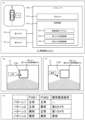
図1は、実施の形態1に係る車両検査システム10の概要及び具体例を示すブロック図である。図1(A)に示すように、車両検査システム10は、車両1に搭載され、車両1を検査する。車両検査システム10が搭載される車両1は、自動運転車両であってもよい。車両検査システム10は、第1カメラ20、第2カメラ30、及びコンピュータ100を含んでいる。
1. First embodiment
1-1. Overview Fig. 1 is a block diagram showing an overview and a specific example of a
第1カメラ20は、車両1の前方に搭載され、車両1の周囲の状況を検出する。第2カメラ30は、車両1の後方に搭載され、車両1の周囲の状況を検出する。
The
コンピュータ100は、第1カメラ20と第2カメラ30とに少なくとも接続されている。コンピュータ100は、1又は複数のプロセッサ110(以下、単にプロセッサ110と呼ぶ)と1又は複数の記憶装置120(以下、単に記憶装置120と呼ぶ)を含んでいる。プロセッサ110は、各種処理を実行する。例えば、プロセッサ110は、CPU(Central Processing Unit)を含んでいる。記憶装置120は、各種情報を格納する。記憶装置120としては、揮発性メモリ、不揮発性メモリ、HDD(Hard Disk Drive)、SSD(Solid State Drive)、等が例示される。典型的には、コンピュータ100は、車両1に搭載されている。
The
記憶装置120は、車両検査プログラム121、第1カメラ取得情報122、第2カメラ取得情報123、等が格納される。
The
車両検査プログラム121は、車両1を検査するためのコンピュータプログラムである。プロセッサ110が車両検査プログラム121を実行することにより、コンピュータ100による各種処理が実現される。車両検査プログラム121は、コンピュータ100が読み取り可能な記録媒体に記録されていてもよい。
The
第1カメラ取得情報122は、車両1の走行中において第1カメラ20により撮影されたカメラ画像(以下、第1カメラ画像と称す)を含んでいる。また、第2カメラ取得情報123は、車両1の走行中において第2カメラ30により撮影されたカメラ画像(以下、第2カメラ画像と称す)を含んでいる。尚、第2カメラ画像は、第1カメラ20による第1カメラ画像の撮影と同時に第2カメラ30により撮影される。
The first camera acquired
更に、第1カメラ取得情報122及び第2カメラ取得情報123は、車両1の周囲の物体に関する物体情報を含む。車両1の周囲の物体としては、歩行者、他車両、白線、道路構造物、障害物、等が例示される。他の例として、カメラによって得られた画像を解析することによって、物体を認識、識別することもできる。
Furthermore, the first camera acquired
1-2.具体例
1-2-1.光軸異常の有無の判定例
プロセッサ110は、第1カメラ20及び第2カメラ30の光軸異常の有無を判定する。以下、光軸異常の有無の判定例の詳細について説明する。
1-2. Specific Examples 1-2-1. Example of Determining Whether or Not There is an Abnormality in the Optical Axis The
プロセッサ110は、第1カメラ取得情報122及び第2カメラ取得情報123を取得し、第1カメラ20及び第2カメラ30のそれぞれの光軸座標値を算出する。具体的には、プロセッサ110は、図1(B)に示すように、第1カメラ画像21に基づいて第1カメラ20の光軸座標値である第1光軸座標値FOE1を算出する。また、プロセッサ110は、図1(C)に示すように、第2カメラ画像31に基づいて第2カメラ30の光軸座標値である第2光軸座標値FOE2を算出する。
The
第1光軸座標値FOE1及び第2光軸座標値FOE2とは、例えば、無限遠距離の点(消失点(FOE:Focus Optical Expansion)とも称す)を意味する。第1光軸座標値FOE1及び第2光軸座標値FOE2の算出例としては、参考文献(特開2011-081613号公報)の技術が挙げられる。この文献によれば、車両1の周囲に存在する道路構造物等の特徴点から得られるオプティカルフローの交点が光軸座標値(FOE)とされる。
The first optical axis coordinate value FOE1 and the second optical axis coordinate value FOE2 refer to, for example, a point at infinity (also called the vanishing point (FOE: Focus Optical Expansion)). An example of calculating the first optical axis coordinate value FOE1 and the second optical axis coordinate value FOE2 is the technology in the reference document (JP Patent Publication 2011-081613). According to this document, the intersection of the optical flows obtained from characteristic points such as road structures present around the
更に、プロセッサ110は、算出された第1光軸座標値FOE1及び第2光軸座標値FOE2のそれぞれについて光軸異常の有無を判定する。
Furthermore, the
まず、第1光軸座標値FOE1における光軸異常の有無の判定について説明する。図1(B)に示すように、第1カメラ取得情報122は、更に、第1所定領域IMG_A1の情報を含んでいる。第1所定領域IMG_A1とは、第1カメラ画像21において光軸座標値が位置すべき位置を中心に設定された所定のサイズの領域であり、光軸異常でないことを示す画像領域を意味する。従って、プロセッサ110は、第1光軸座標値FOE1が第1所定領域IMG_A1に含まれる場合、光軸異常の有無を「無し」と判定する。一方、プロセッサ110は、第1光軸座標値FOE1が第1所定領域IMG_A1に含まれない場合、光軸異常の有無を「有り」と判定する。
First, the determination of the presence or absence of an optical axis abnormality at the first optical axis coordinate value FOE1 will be described. As shown in FIG. 1B, the first camera acquired
続いて、第2光軸座標値FOE2における光軸異常の有無の判定について説明する。図1(C)に示すように、第2カメラ取得情報123は、更に、第2所定領域IMG_A2の情報を含んでいる。第2所定領域IMG_A2とは、第2カメラ画像31において光軸座標値が位置すべき位置を中心に設定された所定のサイズの領域であり、光軸異常でないことを示す画像領域を意味する。従って、プロセッサ110は、第2光軸座標値FOE2が第2所定領域IMG_A2に含まれる場合、光軸異常の有無を「無し」と判定する。一方、プロセッサ110は、第2光軸座標値FOE2が第2所定領域IMG_A2に含まれない場合、光軸異常の有無を「有り」と判定する。尚、第2所定領域IMG_A2のサイズは、第1所定領域IMG_A1と異なるサイズであってもよいし、同じサイズであってもよい。
Next, the determination of the presence or absence of an optical axis abnormality in the second optical axis coordinate value FOE2 will be described. As shown in FIG. 1C, the second camera acquired
尚、光軸異常の有無は、光軸座標値(FOE)が異常となる回数に基づいて判定されてもよい。例えば、第1光軸座標値FOE1が第1所定領域IMG_A1からはみ出た回数が設定された基準回数以上の場合、光軸異常の有無は「有り」と判定される。基準回数は、第1光軸座標値FOE1と第2光軸座標値FOE2のそれぞれで異なっていてもよいし、同じであってもよい。 The presence or absence of an optical axis abnormality may be determined based on the number of times the optical axis coordinate value (FOE) becomes abnormal. For example, if the number of times the first optical axis coordinate value FOE1 goes outside the first predetermined area IMG_A1 is equal to or greater than a set reference number, the presence or absence of an optical axis abnormality is determined to be "present." The reference number may be different for the first optical axis coordinate value FOE1 and the second optical axis coordinate value FOE2, or may be the same.
1-2-2.異常要因箇所の判定例
プロセッサ110は、光軸異常の有無の判定が行われた後、当該光軸異常を生じさせている異常要因箇所を特定する。具体的には、第1光軸座標値FOE1の異常の有無と、第2光軸座標値FOE2の異常の有無との組み合わせに基づいて、異常要因箇所が特定される。例えば、図1(D)に示すように、第1光軸座標値FOE1と第2光軸座標値FOE2の一方に異常が生じている場合(パターン2及びパターン3)を考える。この場合、異常が生じている光軸座標値に対応するカメラが異常要因箇所である可能性が高い。従って、パターン2の場合、異常要因箇所は第2カメラ30と判定され、パターン3の場合、異常要因箇所は第1カメラ20と判定される。
1-2-2. Example of determining abnormality location After determining whether or not there is an optical axis abnormality, the
一方、図1(D)のパターン4に示すように、第1光軸座標値FOE1と第2光軸座標値FOE2の両方に異常が生じている場合を考える。この場合、第1光軸座標値FOE1と第2光軸座標値FOE2の両方が異常であっても、第1カメラ20及び第2カメラ30の両方が異常要因箇所であることは考え難い。むしろ、第1カメラ20及び第2カメラ30が取り付けられている車両の車体に起因して第1光軸座標値FOE1と第2光軸座標値FOE2の両方が異常となっている可能性が高い。従って、パターン4の場合、異常発生箇所は車両1の車体と判定される。
On the other hand, consider the case where an abnormality occurs in both the first optical axis coordinate value FOE1 and the second optical axis coordinate value FOE2, as shown in pattern 4 in FIG. 1(D). In this case, even if both the first optical axis coordinate value FOE1 and the second optical axis coordinate value FOE2 are abnormal, it is unlikely that both the
このように、実施の形態1に係る車両検査システム10では、第1光軸座標値FOE1及び第2光軸座標値FOE2のそれぞれについて異常の有無が判定される。更に、車両検査システム10によれば、第1光軸座標値FOE1の異常の有無と、第2光軸座標値FOE2の異常の有無との組み合わせに基づいて、第1カメラ20、第2カメラ30、及び車両の車体の中から第1光軸座標値FOE1と第2光軸座標値FOE2の一方又は両方に異常を生じさせている異常要因箇所が特定される。これにより、光軸異常が発生した場合であっても、異常要因箇所を短時間で特定することができる。更に、修理を必要とする箇所に限定して修理を行うことが可能となる。
In this way, in the
1-3.処理例
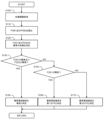
図2は、実施の形態1に係る車両検査システム10の処理例を示すフローチャートである。
2 is a flowchart showing a processing example of the
ステップS100において、プロセッサ110は、第1カメラ取得情報122、第2カメラ取得情報123、等の各種情報を取得する。その後、処理はステップS110に進む。
In step S100, the
ステップS110において、プロセッサ110は、第1カメラ取得情報122に基づいて第1光軸座標値FOE1を算出し、第2カメラ取得情報123に基づいて第2光軸座標値FOE2を算出する。その後、処理はステップS120に進む。
In step S110, the
ステップS120において、プロセッサ110は、第1光軸座標値FOE1の異常の有無を判定し、第2光軸座標値FOE2の異常の有無を判定する。その後、処理はステップS130に進む。
In step S120, the
ステップS130において、プロセッサ110は、第1光軸座標値FOE1に異常が有り、且つ、第2光軸座標値FOE2に異常が有る条件を満たすか否かを判定する。当該条件を満たすと判定された場合(ステップS130;Yes)、処理はステップS140に進む。それ以外の場合(ステップS130;No)、処理はステップS150に進む。
In step S130, the
ステップS140において、プロセッサ110は、第1光軸座標値FOE1と第2光軸座標値FOE2の両方に異常を生じさせている異常要因箇所を車両の車体と判定する。
In step S140, the
ステップS150において、プロセッサ110は、第1光軸座標値FOE1に異常が有るか否かを判定する。第1光軸座標値FOE1に異常が有ると判定された場合(ステップS150;Yes)、処理はステップS160に進む。それ以外の場合(ステップS150;No)、処理はステップS170に進む。
In step S150, the
ステップS160において、プロセッサ110は、第1光軸座標値FOE1にのみ異常を生じさせている異常要因箇所を第1カメラ20と判定する。
In step S160, the
ステップS170において、プロセッサ110は、第2光軸座標値FOE2にのみ異常を生じさせている異常要因箇所を第2カメラ30と判定する。
In step S170, the
2.実施の形態2
2-1.概要
実施の形態1に係る車両検査システム10では、第1光軸座標値FOE1と第2光軸座標値FOE2の両方に異常が有る場合、異常要因箇所は車両1の車体であると判定される。しかし、異常要因箇所と判定された車体の異常要因は様々である。従って、実施の形態2に係る車両検査システム10によれば、異常要因箇所が車体と判定された場合、更に、車体の異常要因を推定する。これにより、実施の形態1の効果に加えて、修理を必要とする箇所を明確にすることが可能となる。以下、実施の形態1と相違する点を中心に説明する。
2. Second embodiment
2-1. Overview In the
ここで、異常要因箇所が車体である場合に推定される異常要因について考える。車体の後方部に位置する後部座席やトランクルームの総積載量が最大積載量を超えている場合(すなわち、車両1が過積載の状態である場合)、車体を水平に維持することができず、車体の後方部が水平に対して地面側に沈むように傾くことが想定される。よって、車体の異常要因の一例としては、車体の後方部の車高が著しく低くなることが想定される。尚、車体の後方部には、典型的には、車高を計測することができるハイトセンサが設けられている。従って、実施の形態2に係る車両検査システム10によれば、ハイトセンサから得られた車高の情報に基づいて、異常要因箇所が車体である場合の異常要因が車両1の過積載であるか否かが推定される。
Here, let us consider the abnormality factor that is estimated when the abnormality factor location is the vehicle body. When the total load capacity of the rear seats and trunk located in the rear part of the vehicle body exceeds the maximum load capacity (i.e., when the
図3は、実施の形態2に係る車両検査システム10の概要及び具体例を示すブロック図である。具体的には、図3(A)に示すように、車両検査システム10は、更に、ハイトセンサ40を含んでいる。ハイトセンサ40は、上述したように、車体に設けられ、車体の車高を計測するセンサである。記憶装置120は、ハイトセンサ40から取得された車高情報124が更に格納される。
Figure 3 is a block diagram showing an overview and a specific example of the
2-2.具体例
上述した異常要因箇所の判定例において、異常要因箇所が車体であると判定された場合、プロセッサ110は、車高情報124に基づいて、異常要因の推定を行う。具体的には、図3(B)に示すように、プロセッサ110は、車体が異常要因箇所と特定され、且つ、ハイトセンサ40から取得された車高が閾値未満である場合(パターン4(a))、異常要因を車両1の過積載と推定する。一方、ハイトセンサ40から取得された車高が閾値以上である場合(パターン4(b))、つまり、異常要因が車両1の過積載でない場合、車体の構造が変形していることが想定される。従って、この場合、プロセッサ110は、異常要因を車体の構造変形と推定する。
2-2. Specific Example In the above-described example of determining the abnormality factor location, when it is determined that the abnormality factor location is the vehicle body, the
2-3.処理例
図4は、実施の形態2に係る車両検査システム10の処理例を示すフローチャートである。
2-3. Processing Example FIG. 4 is a flowchart showing a processing example of the
ステップS200において、プロセッサ110は、上述したステップS140において異常要因箇所が車体と判定された場合、車高情報124を取得する。その後、処理はステップS210に進む。
In step S200, if the abnormality location is determined to be the vehicle body in step S140 described above, the
ステップS210において、プロセッサ110は、車高が閾値未満か否かを判定する。車高が閾値未満と判定された場合(ステップS210;Yes)、処理はステップS220に進む。それ以外の場合(ステップS210;No)、処理はステップS230に進む。
In step S210, the
ステップS220において、プロセッサ110は、異常要因を車両1の過積載と推定する。
In step S220, the
ステップS230において、プロセッサ110は、異常要因を車体の構造変形と推定する。
In step S230, the
3.実施の形態3
3-1.概要
実施の形態1に係る車両検査システム10では、第1光軸座標値FOE1と第2光軸座標値FOE2の一方に異常が有る場合、異常要因箇所は異常を有する光軸座標値に対応するカメラ(すなわち、第1カメラ20あるいは第2カメラ30)であると判定される。しかし、カメラの異常要因は様々である。従って、実施の形態3に係る車両検査システム10によれば、異常要因箇所が第1カメラ20又は第2カメラ30と判定された場合、更に、カメラの異常要因を推定する。これにより、実施の形態1の効果に加えて、修理を必要とする箇所を明確にすることが可能となる。以下、実施の形態1と相違する点を中心に説明する。
3. Third embodiment
3-1. Overview In the
ここで、異常要因箇所が第1カメラ20又は第2カメラ30である場合の異常要因について考える。車両1に搭載されたカメラは、車体に固定して取り付けられている。このため、カメラの異常要因の一例としては、車両1の走行中における車両1の振動等により、車体に取り付けられているカメラの位置がずれることが想定される。従って、実施の形態2に係る車両検査システム10によれば、異常要因箇所が第1カメラ20又は第2カメラ30である場合、カメラの位置のずれを検出した情報に基づいて、異常要因がカメラの位置のずれか否かが推定される。
Now, let us consider the cause of the abnormality when the location causing the abnormality is the
図5は、実施の形態3に係る車両検査システム10の概要及び具体例を示すブロック図である。具体的には、図5(A)に示すように、車両検査システム10は、更に、第1センサ50、及び第2センサ60を含んでいる。第1センサ50は、第1カメラ20に取り付けられ、第1カメラ20の姿勢角を計測するセンサである。第2センサ60は、第2カメラ30に取り付けられ、第2カメラ30の姿勢角を計測するセンサである。記憶装置120は、第1センサ50から取得された第1姿勢角情報125と、第2センサ60から取得された第2姿勢角情報126とが更に格納される。姿勢角を計測するセンサとしては、ジャイロセンサ、等が例示される。また、姿勢角とは、例えば、Yaw方向、Pitch方向、及びRoll方向の回転角で示される。
Figure 5 is a block diagram showing an overview and a specific example of the
3-2.具体例
上述した異常要因箇所の判定例において、異常要因箇所が第1カメラ20であると判定された場合、プロセッサ110は、第1姿勢角情報125に基づいて、異常要因の推定を行う。具体的には、図5(B)に示すように、プロセッサ110は、第2カメラ30が異常要因箇所と特定され、且つ、第2センサ60から取得された第2カメラ30の姿勢角(第2姿勢角)が許容範囲外である場合(パターン2(a))、異常要因を車体に取り付けられた第2カメラ30の位置のずれと推定する。一方、第2姿勢角が許容範囲内である場合(パターン2(b))、第2カメラ30の内部が故障していることが想定される。従って、この場合、プロセッサ110は、異常要因を第2カメラ30の内部の故障と推定する。尚、上述した異常要因箇所の判定例において、異常要因箇所が第1カメラ20であると判定された場合、第2カメラ30と同様の処理が行われるので、ここでは説明を省略する。
3-2. Specific Example In the above-described example of determining the abnormality cause location, if it is determined that the abnormality cause location is the
3-3.処理例
図6は、実施の形態3に係る車両検査システム10の処理例を示すフローチャートである。具体的には、図6(A)は、第1カメラ20の異常要因を推定する処理例のフローチャートであり、図6(B)は、第2カメラ30の異常要因を推定する処理例のフローチャートである。
6 is a flowchart showing a processing example of the
図6(A)のフローチャートによれば、ステップS300において、プロセッサ110は、上述したステップS160において異常要因箇所が第1カメラ20と判定された場合、第1姿勢角情報125を取得する。その後、処理はステップS310に進む。
According to the flowchart in FIG. 6(A), in step S300, if the
ステップS310において、プロセッサ110は、第1姿勢角が許容範囲外か否かを判定する。第1姿勢角が許容範囲外と判定された場合(ステップS310;Yes)、処理はステップS320に進む。それ以外の場合(ステップS310;No)、処理はステップS330に進む。
In step S310, the
ステップS320において、プロセッサ110は、異常要因を第1カメラ20の位置のずれと推定する。
In step S320, the
ステップS330において、プロセッサ110は、異常要因を第1カメラ20の内部の故障と推定する。
In step S330, the
尚、図6(B)のフローチャートに示すステップS400-ステップS430では、上述したステップS300-ステップS330と同様の処理が行われるので、ここでは説明を省略する。 Note that in steps S400 to S430 shown in the flowchart in FIG. 6B, the same processing as in steps S300 to S330 described above is performed, so a description thereof will be omitted here.
4.その他の実施形態
4-1.第1の例
その他の実施形態に係る車両検査システム10によれば、上述した異常要因の推定が行われた後、修理を必要とする箇所の修理を促す警報が乗員に通知される。これにより、販売店等による診断及び修理を早期に行うことが可能となる。修理を必要とする箇所とは、異常要因が第1カメラ20の内部の故障あるいは位置のずれであることと、異常要因が第2カメラ30の内部の故障あるいは位置のずれであることと、異常要因が車体の構造変形であることと、のうちいずれかを含むことを意味する。
4. Other embodiments 4-1. First example According to the
4-2.第2の例
その他の実施形態に係る車両検査システム10によれば、異常要因箇所の判定結果と異常要因の推定結果の少なくとも一方の結果がエンジンを再起動させても保持される。これにより、エンジンの再起動により異常要因箇所が正常に復帰した場合であっても、一度異常と判定された結果の情報が乗員に通知され続ける。従って、販売店等による診断及び修理を早期に行うことが可能となる。
4-2. Second Example According to the
1…車両, 10…車両検査システム, 20…第1カメラ, 21…第1カメラ画像, 30…第2カメラ, 31…第2カメラ画像, 40…ハイトセンサ, 50…第1センサ, 60…第2センサ, 100…コンピュータ, 110…プロセッサ, 120…記憶装置, 121…車両検査プログラム, 122…第1カメラ取得情報, 123…第2カメラ取得情報, 124…車高情報, 125…第1姿勢角情報, 126…第2姿勢角情報, FOE1…第1光軸座標値, FOE2…第2光軸座標値, IMG_A1…第1所定領域, IMG_A2…第2所定領域 1...vehicle, 10...vehicle inspection system, 20...first camera, 21...first camera image, 30...second camera, 31...second camera image, 40...height sensor, 50...first sensor, 60...second sensor, 100...computer, 110...processor, 120...storage device, 121...vehicle inspection program, 122...information acquired by first camera, 123...information acquired by second camera, 124...vehicle height information, 125...first attitude angle information, 126...second attitude angle information, FOE1...first optical axis coordinate value, FOE2...second optical axis coordinate value, IMG_A1...first specified area, IMG_A2...second specified area
Claims (5)
前記車両の前方に搭載された第1カメラと前記車両の後方に搭載された第2カメラとに接続されたコンピュータを備え、
前記コンピュータは、
前記車両の走行中において前記第1カメラにより撮影された第1カメラ画像を取得するとともに、前記第1カメラによる前記第1カメラ画像の撮影と同時に前記第2カメラにより撮影された第2カメラ画像を取得し、
前記第1カメラ画像から第1光軸座標値を算出し、
前記第2カメラ画像から第2光軸座標値を算出し、
前記第1光軸座標値と前記第2光軸座標値のそれぞれについて異常の有無を判定し、
前記第1光軸座標値の異常の有無と、前記第2光軸座標値の異常の有無との組み合わせに基づいて、前記第1カメラ、前記第2カメラ、及び前記車両の車体の中から前記第1光軸座標値と前記第2光軸座標値の一方又は両方に異常を生じさせている異常要因箇所を特定するように構成されている
ことを特徴とする車両検査システム。 A vehicle inspection system for inspecting a vehicle, comprising:
a computer connected to a first camera mounted at the front of the vehicle and a second camera mounted at the rear of the vehicle;
The computer includes:
acquiring a first camera image taken by the first camera while the vehicle is traveling, and acquiring a second camera image taken by the second camera simultaneously with the first camera taking the first camera image;
Calculating a first optical axis coordinate value from the first camera image;
Calculating a second optical axis coordinate value from the second camera image;
determining whether or not there is an abnormality with respect to each of the first optical axis coordinate value and the second optical axis coordinate value;
a vehicle inspection system configured to identify an abnormality factor location causing an abnormality in one or both of the first optical axis coordinate value and the second optical axis coordinate value from among the first camera, the second camera, and a body of the vehicle, based on a combination of the presence or absence of an abnormality in the first optical axis coordinate value and the presence or absence of an abnormality in the second optical axis coordinate value.
前記コンピュータは、
前記第1光軸座標値に異常が有り前記第2光軸座標値に異常が無い場合、前記異常要因箇所を前記第1カメラと特定し、
前記第2光軸座標値に異常が有り前記第1光軸座標値に異常が無い場合、前記異常要因箇所を前記第2カメラと判定し、
前記第1光軸座標値と前記第2光軸座標値の両方に異常が有る場合、前記異常要因箇所を前記車体と特定するように構成されている
ことを特徴とする車両検査システム。 2. A vehicle inspection system according to claim 1,
The computer includes:
If there is an abnormality in the first optical axis coordinate value and there is no abnormality in the second optical axis coordinate value, the abnormality cause location is identified as the first camera;
When an abnormality is present in the second optical axis coordinate value and an abnormality is not present in the first optical axis coordinate value, the abnormality location is determined to be the second camera;
a vehicle inspection system configured to identify the vehicle body as a location causing the abnormality when an abnormality is detected in both the first optical axis coordinate value and the second optical axis coordinate value.
更に、前記車体に設けられたハイトセンサを含み、
前記コンピュータは、
前記車体が前記異常要因箇所と特定され、且つ、前記ハイトセンサから取得された車高が閾値以上である場合、異常要因を前記車体の構造変形と推定し、
前記車体が前記異常要因箇所と特定され、且つ、前記車高が前記閾値未満である場合、前記異常要因を前記車両の過積載と推定するように構成されている
ことを特徴とする車両検査システム。 3. A vehicle inspection system according to claim 2,
Further, a height sensor provided on the vehicle body,
The computer includes:
When the vehicle body is identified as the abnormality causing portion and the vehicle height acquired from the height sensor is equal to or greater than a threshold value, the abnormality causing portion is estimated to be a structural deformation of the vehicle body;
a vehicle inspection system configured to estimate, when the vehicle body is identified as the abnormality causing portion and the vehicle height is less than the threshold value, that the abnormality causing portion is an overload of the vehicle.
更に、前記第1カメラの姿勢角を計測する第1センサと、前記第2カメラの姿勢角を計測する第2センサと、を備え、
前記コンピュータは、
前記第1カメラが前記異常要因箇所と特定され、且つ、前記第1センサから取得された第1姿勢角が許容範囲内である場合、異常要因を前記第1カメラの内部の故障と推定し、
前記第1カメラが前記異常要因箇所と特定され、且つ、前記第1姿勢角が前記許容範囲外である場合、前記異常要因を前記車体に取り付けられた前記第1カメラの位置のずれと推定し、
前記第2カメラが前記異常要因箇所と特定され、且つ、前記第2センサから取得された第2姿勢角が前記許容範囲内である場合、前記異常要因を前記第2カメラの内部の故障と推定し、
前記第2カメラが前記異常要因箇所と特定され、且つ、前記第2姿勢角が前記許容範囲外である場合、前記異常要因を前記車体に取り付けられた前記第2カメラの位置のずれと推定するように構成されている
ことを特徴とする車両検査システム。 3. A vehicle inspection system according to claim 2,
a first sensor that measures an attitude angle of the first camera and a second sensor that measures an attitude angle of the second camera,
The computer includes:
When the first camera is identified as the location causing the abnormality and the first attitude angle acquired from the first sensor is within a permissible range, the cause of the abnormality is estimated to be an internal failure of the first camera;
When the first camera is identified as the location causing the abnormality and the first attitude angle is outside the allowable range, the cause of the abnormality is estimated to be a deviation in position of the first camera attached to the vehicle body;
when the second camera is identified as the location causing the abnormality and the second attitude angle acquired from the second sensor is within the allowable range, the cause of the abnormality is estimated to be an internal failure of the second camera;
a vehicle inspection system configured to estimate, when the second camera is identified as the location causing the abnormality and the second attitude angle is outside the allowable range, that the cause of the abnormality is a deviation in position of the second camera attached to the vehicle body.
前記車両の走行中において前記車両の前方に搭載された第1カメラにより撮影された第1カメラ画像を取得するとともに、前記第1カメラによる前記第1カメラ画像の撮影と同時に前記車両の後方に搭載された第2カメラにより撮影された第2カメラ画像を取得することと、
前記第1カメラ画像から第1光軸座標値を算出することと、
前記第2カメラ画像から第2光軸座標値を算出することと、
前記第1光軸座標値と前記第2光軸座標値のそれぞれについて異常の有無を判定することと、
前記第1光軸座標値の異常の有無と、前記第2光軸座標値の異常の有無との組み合わせに基づいて、前記第1カメラ、前記第2カメラ、及び前記車両の車体の中から前記第1光軸座標値と前記第2光軸座標値の一方又は両方に異常を生じさせている異常要因箇所を特定することと、
を含む
ことを特徴とする車両検査方法。 A vehicle inspection method for inspecting a vehicle, comprising:
acquiring a first camera image taken by a first camera mounted on a front side of the vehicle while the vehicle is traveling, and acquiring a second camera image taken by a second camera mounted on a rear side of the vehicle simultaneously with the first camera image being taken by the first camera;
Calculating a first optical axis coordinate value from the first camera image;
Calculating a second optical axis coordinate value from the second camera image;
determining whether or not there is an abnormality with respect to each of the first optical axis coordinate value and the second optical axis coordinate value;
Identifying an abnormality factor location causing an abnormality in one or both of the first optical axis coordinate value and the second optical axis coordinate value from among the first camera, the second camera, and the vehicle body based on a combination of the presence or absence of an abnormality in the first optical axis coordinate value and the presence or absence of an abnormality in the second optical axis coordinate value;
A vehicle inspection method comprising:
Priority Applications (3)
| Application Number | Priority Date | Filing Date | Title |
|---|---|---|---|
| JP2022174705A JP7635772B2 (en) | 2022-10-31 | 2022-10-31 | Vehicle inspection system and vehicle inspection method |
| US18/365,743 US20240144752A1 (en) | 2022-10-31 | 2023-08-04 | Vehicle inspection system and vehicle inspection method |
| CN202311371309.7A CN117956136A (en) | 2022-10-31 | 2023-10-23 | Vehicle inspection system and vehicle inspection method |
Applications Claiming Priority (1)
| Application Number | Priority Date | Filing Date | Title |
|---|---|---|---|
| JP2022174705A JP7635772B2 (en) | 2022-10-31 | 2022-10-31 | Vehicle inspection system and vehicle inspection method |
Publications (2)
| Publication Number | Publication Date |
|---|---|
| JP2024065708A JP2024065708A (en) | 2024-05-15 |
| JP7635772B2 true JP7635772B2 (en) | 2025-02-26 |
Family
ID=90793369
Family Applications (1)
| Application Number | Title | Priority Date | Filing Date |
|---|---|---|---|
| JP2022174705A Active JP7635772B2 (en) | 2022-10-31 | 2022-10-31 | Vehicle inspection system and vehicle inspection method |
Country Status (3)
| Country | Link |
|---|---|
| US (1) | US20240144752A1 (en) |
| JP (1) | JP7635772B2 (en) |
| CN (1) | CN117956136A (en) |
Citations (6)
| Publication number | Priority date | Publication date | Assignee | Title |
|---|---|---|---|---|
| JP2004247979A (en) | 2003-02-14 | 2004-09-02 | Hitachi Ltd | In-vehicle camera device |
| JP2013107439A (en) | 2011-11-18 | 2013-06-06 | Toshiba Alpine Automotive Technology Corp | Calibration apparatus for vehicle mounted camera |
| JP2014195170A (en) | 2013-03-28 | 2014-10-09 | Honda Motor Co Ltd | Driving support device |
| CN206961189U (en) | 2017-06-07 | 2018-02-02 | 德尔福电子(苏州)有限公司 | A kind of optical axis deflection measurement apparatus of vehicle-mounted camera |
| JP2019191807A (en) | 2018-04-23 | 2019-10-31 | 株式会社デンソーテン | Abnormality detection device and abnormality detection method |
| US20220103730A1 (en) | 2020-09-28 | 2022-03-31 | Argo AI, LLC | Enhanced pointing angle validation |
Family Cites Families (1)
| Publication number | Priority date | Publication date | Assignee | Title |
|---|---|---|---|---|
| JP2022042167A (en) * | 2020-09-02 | 2022-03-14 | トヨタ自動車株式会社 | On-vehicle camera calibration device |
-
2022
- 2022-10-31 JP JP2022174705A patent/JP7635772B2/en active Active
-
2023
- 2023-08-04 US US18/365,743 patent/US20240144752A1/en not_active Abandoned
- 2023-10-23 CN CN202311371309.7A patent/CN117956136A/en active Pending
Patent Citations (6)
| Publication number | Priority date | Publication date | Assignee | Title |
|---|---|---|---|---|
| JP2004247979A (en) | 2003-02-14 | 2004-09-02 | Hitachi Ltd | In-vehicle camera device |
| JP2013107439A (en) | 2011-11-18 | 2013-06-06 | Toshiba Alpine Automotive Technology Corp | Calibration apparatus for vehicle mounted camera |
| JP2014195170A (en) | 2013-03-28 | 2014-10-09 | Honda Motor Co Ltd | Driving support device |
| CN206961189U (en) | 2017-06-07 | 2018-02-02 | 德尔福电子(苏州)有限公司 | A kind of optical axis deflection measurement apparatus of vehicle-mounted camera |
| JP2019191807A (en) | 2018-04-23 | 2019-10-31 | 株式会社デンソーテン | Abnormality detection device and abnormality detection method |
| US20220103730A1 (en) | 2020-09-28 | 2022-03-31 | Argo AI, LLC | Enhanced pointing angle validation |
Also Published As
| Publication number | Publication date |
|---|---|
| US20240144752A1 (en) | 2024-05-02 |
| JP2024065708A (en) | 2024-05-15 |
| CN117956136A (en) | 2024-04-30 |
Similar Documents
| Publication | Publication Date | Title |
|---|---|---|
| US7580548B2 (en) | Abnormality detecting apparatus for imaging apparatus | |
| KR20190039648A (en) | Method for monotoring blind spot of vehicle and blind spot monitor using the same | |
| CN112041886B (en) | Identifying a vehicle contour from measurement data of a surrounding environment sensor | |
| US12112506B2 (en) | System for calibrating extrinsic parameters for a camera in an autonomous vehicle | |
| JP2006240453A (en) | Sensor failure detector and detection method of sensor failure | |
| WO2019181591A1 (en) | In-vehicle stereo camera | |
| US11390218B2 (en) | Vehicle periphery monitoring device, vehicle periphery monitoring method and non-transitory storage medium | |
| JP6350113B2 (en) | Image processing apparatus and fault diagnosis method for image processing apparatus | |
| WO2019068699A1 (en) | Method for classifying an object point as static or dynamic, driver assistance system, and motor vehicle | |
| CN112740302A (en) | Monitoring device for vehicle | |
| CN111989541A (en) | Stereo camera device | |
| CN117429440A (en) | Careless driving determination device and careless driving determination method | |
| JP7635772B2 (en) | Vehicle inspection system and vehicle inspection method | |
| JP2011159214A (en) | Action detection device | |
| KR20210060779A (en) | Apparatus for diagnosing abnormality of vehicle sensor and method thereof | |
| CN113168701A (en) | Method for camera misalignment detection, camera system, computer program product and computer readable medium | |
| JP7207163B2 (en) | Anomaly detection device, anomaly detection method, anomaly detection program | |
| JP4601376B2 (en) | Image abnormality determination device | |
| JP7206938B2 (en) | Movement amount calculator | |
| US11993274B2 (en) | Monitoring of on-board vehicle image capturing device functionality compliance | |
| CN118019957A (en) | Tilt detection device, tilt detection system, tilt detection method and tilt detection program | |
| JP2022072304A (en) | Drive recorder system, method for controlling drive recorder system, and control program for drive recorder system | |
| US20230351631A1 (en) | Information processing apparatus, information processing method, and computer-readable recording medium | |
| JP2024047398A (en) | Information processing device, information processing method, and program | |
| JP2010030521A (en) | Moving amount specifying device, leveling control device and program |
Legal Events
| Date | Code | Title | Description |
|---|---|---|---|
| A621 | Written request for application examination |
Free format text: JAPANESE INTERMEDIATE CODE: A621 Effective date: 20240524 |
|
| A977 | Report on retrieval |
Free format text: JAPANESE INTERMEDIATE CODE: A971007 Effective date: 20241225 |
|
| TRDD | Decision of grant or rejection written | ||
| A01 | Written decision to grant a patent or to grant a registration (utility model) |
Free format text: JAPANESE INTERMEDIATE CODE: A01 Effective date: 20250114 |
|
| A61 | First payment of annual fees (during grant procedure) |
Free format text: JAPANESE INTERMEDIATE CODE: A61 Effective date: 20250127 |
|
| R150 | Certificate of patent or registration of utility model |
Ref document number: 7635772 Country of ref document: JP Free format text: JAPANESE INTERMEDIATE CODE: R150 |